KR20140109280A - Battery Cell Having Electrode Assembly of Stair-like Structure - Google Patents
Battery Cell Having Electrode Assembly of Stair-like Structure Download PDFInfo
- Publication number
- KR20140109280A KR20140109280A KR1020140023211A KR20140023211A KR20140109280A KR 20140109280 A KR20140109280 A KR 20140109280A KR 1020140023211 A KR1020140023211 A KR 1020140023211A KR 20140023211 A KR20140023211 A KR 20140023211A KR 20140109280 A KR20140109280 A KR 20140109280A
- Authority
- KR
- South Korea
- Prior art keywords
- electrode
- sheet
- electrode roll
- battery cell
- roll
- Prior art date
- Legal status (The legal status is an assumption and is not a legal conclusion. Google has not performed a legal analysis and makes no representation as to the accuracy of the status listed.)
- Granted
Links
Images



Classifications
-
- H—ELECTRICITY
- H01—ELECTRIC ELEMENTS
- H01M—PROCESSES OR MEANS, e.g. BATTERIES, FOR THE DIRECT CONVERSION OF CHEMICAL ENERGY INTO ELECTRICAL ENERGY
- H01M10/00—Secondary cells; Manufacture thereof
- H01M10/05—Accumulators with non-aqueous electrolyte
- H01M10/058—Construction or manufacture
- H01M10/0587—Construction or manufacture of accumulators having only wound construction elements, i.e. wound positive electrodes, wound negative electrodes and wound separators
-
- H—ELECTRICITY
- H01—ELECTRIC ELEMENTS
- H01M—PROCESSES OR MEANS, e.g. BATTERIES, FOR THE DIRECT CONVERSION OF CHEMICAL ENERGY INTO ELECTRICAL ENERGY
- H01M10/00—Secondary cells; Manufacture thereof
- H01M10/04—Construction or manufacture in general
- H01M10/0431—Cells with wound or folded electrodes
-
- H—ELECTRICITY
- H01—ELECTRIC ELEMENTS
- H01M—PROCESSES OR MEANS, e.g. BATTERIES, FOR THE DIRECT CONVERSION OF CHEMICAL ENERGY INTO ELECTRICAL ENERGY
- H01M10/00—Secondary cells; Manufacture thereof
- H01M10/05—Accumulators with non-aqueous electrolyte
- H01M10/052—Li-accumulators
- H01M10/0525—Rocking-chair batteries, i.e. batteries with lithium insertion or intercalation in both electrodes; Lithium-ion batteries
-
- H—ELECTRICITY
- H01—ELECTRIC ELEMENTS
- H01M—PROCESSES OR MEANS, e.g. BATTERIES, FOR THE DIRECT CONVERSION OF CHEMICAL ENERGY INTO ELECTRICAL ENERGY
- H01M50/00—Constructional details or processes of manufacture of the non-active parts of electrochemical cells other than fuel cells, e.g. hybrid cells
- H01M50/10—Primary casings; Jackets or wrappings
- H01M50/102—Primary casings; Jackets or wrappings characterised by their shape or physical structure
-
- H—ELECTRICITY
- H01—ELECTRIC ELEMENTS
- H01M—PROCESSES OR MEANS, e.g. BATTERIES, FOR THE DIRECT CONVERSION OF CHEMICAL ENERGY INTO ELECTRICAL ENERGY
- H01M50/00—Constructional details or processes of manufacture of the non-active parts of electrochemical cells other than fuel cells, e.g. hybrid cells
- H01M50/10—Primary casings; Jackets or wrappings
- H01M50/116—Primary casings; Jackets or wrappings characterised by the material
- H01M50/117—Inorganic material
- H01M50/119—Metals
-
- H—ELECTRICITY
- H01—ELECTRIC ELEMENTS
- H01M—PROCESSES OR MEANS, e.g. BATTERIES, FOR THE DIRECT CONVERSION OF CHEMICAL ENERGY INTO ELECTRICAL ENERGY
- H01M50/00—Constructional details or processes of manufacture of the non-active parts of electrochemical cells other than fuel cells, e.g. hybrid cells
- H01M50/10—Primary casings; Jackets or wrappings
- H01M50/116—Primary casings; Jackets or wrappings characterised by the material
- H01M50/121—Organic material
-
- H—ELECTRICITY
- H01—ELECTRIC ELEMENTS
- H01M—PROCESSES OR MEANS, e.g. BATTERIES, FOR THE DIRECT CONVERSION OF CHEMICAL ENERGY INTO ELECTRICAL ENERGY
- H01M50/00—Constructional details or processes of manufacture of the non-active parts of electrochemical cells other than fuel cells, e.g. hybrid cells
- H01M50/10—Primary casings; Jackets or wrappings
- H01M50/116—Primary casings; Jackets or wrappings characterised by the material
- H01M50/124—Primary casings; Jackets or wrappings characterised by the material having a layered structure
-
- H—ELECTRICITY
- H01—ELECTRIC ELEMENTS
- H01M—PROCESSES OR MEANS, e.g. BATTERIES, FOR THE DIRECT CONVERSION OF CHEMICAL ENERGY INTO ELECTRICAL ENERGY
- H01M50/00—Constructional details or processes of manufacture of the non-active parts of electrochemical cells other than fuel cells, e.g. hybrid cells
- H01M50/40—Separators; Membranes; Diaphragms; Spacing elements inside cells
- H01M50/46—Separators, membranes or diaphragms characterised by their combination with electrodes
-
- H—ELECTRICITY
- H01—ELECTRIC ELEMENTS
- H01M—PROCESSES OR MEANS, e.g. BATTERIES, FOR THE DIRECT CONVERSION OF CHEMICAL ENERGY INTO ELECTRICAL ENERGY
- H01M2220/00—Batteries for particular applications
- H01M2220/10—Batteries in stationary systems, e.g. emergency power source in plant
-
- H—ELECTRICITY
- H01—ELECTRIC ELEMENTS
- H01M—PROCESSES OR MEANS, e.g. BATTERIES, FOR THE DIRECT CONVERSION OF CHEMICAL ENERGY INTO ELECTRICAL ENERGY
- H01M2220/00—Batteries for particular applications
- H01M2220/20—Batteries in motive systems, e.g. vehicle, ship, plane
-
- H—ELECTRICITY
- H01—ELECTRIC ELEMENTS
- H01M—PROCESSES OR MEANS, e.g. BATTERIES, FOR THE DIRECT CONVERSION OF CHEMICAL ENERGY INTO ELECTRICAL ENERGY
- H01M2220/00—Batteries for particular applications
- H01M2220/30—Batteries in portable systems, e.g. mobile phone, laptop
-
- Y—GENERAL TAGGING OF NEW TECHNOLOGICAL DEVELOPMENTS; GENERAL TAGGING OF CROSS-SECTIONAL TECHNOLOGIES SPANNING OVER SEVERAL SECTIONS OF THE IPC; TECHNICAL SUBJECTS COVERED BY FORMER USPC CROSS-REFERENCE ART COLLECTIONS [XRACs] AND DIGESTS
- Y02—TECHNOLOGIES OR APPLICATIONS FOR MITIGATION OR ADAPTATION AGAINST CLIMATE CHANGE
- Y02E—REDUCTION OF GREENHOUSE GAS [GHG] EMISSIONS, RELATED TO ENERGY GENERATION, TRANSMISSION OR DISTRIBUTION
- Y02E60/00—Enabling technologies; Technologies with a potential or indirect contribution to GHG emissions mitigation
- Y02E60/10—Energy storage using batteries
-
- Y—GENERAL TAGGING OF NEW TECHNOLOGICAL DEVELOPMENTS; GENERAL TAGGING OF CROSS-SECTIONAL TECHNOLOGIES SPANNING OVER SEVERAL SECTIONS OF THE IPC; TECHNICAL SUBJECTS COVERED BY FORMER USPC CROSS-REFERENCE ART COLLECTIONS [XRACs] AND DIGESTS
- Y02—TECHNOLOGIES OR APPLICATIONS FOR MITIGATION OR ADAPTATION AGAINST CLIMATE CHANGE
- Y02P—CLIMATE CHANGE MITIGATION TECHNOLOGIES IN THE PRODUCTION OR PROCESSING OF GOODS
- Y02P70/00—Climate change mitigation technologies in the production process for final industrial or consumer products
- Y02P70/50—Manufacturing or production processes characterised by the final manufactured product
-
- Y—GENERAL TAGGING OF NEW TECHNOLOGICAL DEVELOPMENTS; GENERAL TAGGING OF CROSS-SECTIONAL TECHNOLOGIES SPANNING OVER SEVERAL SECTIONS OF THE IPC; TECHNICAL SUBJECTS COVERED BY FORMER USPC CROSS-REFERENCE ART COLLECTIONS [XRACs] AND DIGESTS
- Y02—TECHNOLOGIES OR APPLICATIONS FOR MITIGATION OR ADAPTATION AGAINST CLIMATE CHANGE
- Y02T—CLIMATE CHANGE MITIGATION TECHNOLOGIES RELATED TO TRANSPORTATION
- Y02T10/00—Road transport of goods or passengers
- Y02T10/60—Other road transportation technologies with climate change mitigation effect
- Y02T10/70—Energy storage systems for electromobility, e.g. batteries
Landscapes
- Chemical & Material Sciences (AREA)
- Chemical Kinetics & Catalysis (AREA)
- Electrochemistry (AREA)
- General Chemical & Material Sciences (AREA)
- Engineering & Computer Science (AREA)
- Manufacturing & Machinery (AREA)
- Secondary Cells (AREA)
- Inorganic Chemistry (AREA)
- Materials Engineering (AREA)
Abstract
Description
본 발명은 계단 구조의 전극조립체를 포함하는 전지셀에 관한 것으로, 더욱 상세하게는, 양극 시트, 음극 시트, 상기 음극 시트와 양극 시트의 사이에 개재되는 제 1 분리 시트, 및 상기 음극 시트 또는 양극 시트를 사이에 두고 상기 제 1 분리시트와 대면하는 제 2 분리 시트로 이루어진 조립 전극 시트를 포함하고, 상기 조립 전극 시트의 일단과 타단을 각각 권취한 구조의 제 1 전극 롤 및 제 2 전극 롤을 포함하며, 상기 제 1 전극 롤의 높이는 제 2 전극 롤의 높이보다 큰 구조로 형성되어 있는 전극조립체, 및 상기 전극조립체의 외면에 대응하는 형상으로 이루어진 전지셀 케이스를 포함하는 것을 특징으로 하는 전지셀에 관한 것이다.The present invention relates to a battery cell including a stepped electrode assembly, and more particularly to a battery cell including a positive electrode sheet, a negative electrode sheet, a first separator interposed between the negative electrode sheet and the positive electrode sheet, And a second separating sheet facing the first separating sheet with a sheet interposed therebetween, wherein the first electrode roll and the second electrode roll have a structure in which one end and the other end of the assembled electrode sheet are wound, Wherein the first electrode roll has a height greater than a height of the second electrode roll, and a battery cell case having a shape corresponding to an outer surface of the electrode assembly. .
IT(Information Technology) 기술이 눈부시게 발달함에 따라 다양한 휴대형 정보통신 기기의 확산이 이뤄짐으로써, 21세기는 시간과 장소에 구애 받지 않고 고품질의 정보서비스가 가능한 ‘유비쿼터스 사회’로 발전되고 있다. As information technology (IT) technology has developed remarkably, various portable information and communication devices have been spreading, so that the 21st century is being developed into a "ubiquitous society" capable of providing high quality information services regardless of time and place.
이러한 유비쿼터스 사회로의 발전 기반에는, 이차전지가 중요한 위치를 차지하고 있다. 구체적으로, 충방전이 가능한 이차전지는 와이어리스 모바일 기기의 에너지원으로 광범위하게 사용되고 있을 뿐만 아니라, 화석 연료를 사용하는 기존의 가솔린 차량, 디젤 차량 등의 대기오염 등을 해결하기 위한 방안으로 제시되고 있는 전기자동차, 하이브리드 전기자동차 등의 에너지원으로서도 사용되고 있다. In the development base for such a ubiquitous society, a secondary battery occupies an important position. Specifically, the rechargeable secondary cell is widely used as an energy source for wireless mobile devices, and is proposed as a solution for air pollution in existing gasoline vehicles and diesel vehicles using fossil fuels Electric vehicles, hybrid electric vehicles, and the like.
상기와 같이, 이차전지가 적용되는 디바이스들이 다양화됨에 따라, 리튬 이차전지는, 적용되는 디바이스에 알맞은 출력과 용량을 제공할 수 있도록 다양화되고 있고, 더불어, 소형 경박화가 강력히 요구되고 있다. As described above, as the devices to which the secondary battery is applied are diversified, the lithium secondary battery has been diversified to provide an appropriate output and capacity for the applied device. In addition, miniaturization and miniaturization are strongly demanded.
이러한 이차전지는 전지케이스의 형상에 따라, 전극조립체가 원통형 또는 각형의 금속 캔에 내장되어 있는 원통형 전지 및 각형 전지와, 전극조립체가 알루미늄 라미네이트 시트의 파우치형 케이스에 내장되어 있는 파우치형 전지로 분류된다.Such a secondary battery is classified into a cylindrical battery and a prismatic battery in which an electrode assembly is embedded in a cylindrical or rectangular metal can according to the shape of the battery case, and a pouch type battery in which an electrode assembly is embedded in a pouch-shaped case of an aluminum laminate sheet do.
또한, 전지케이스에 내장되는 상기 전극조립체는 양극/분리막/음극의 적층 구조로 이루어진 충방전이 가능한 발전소자로서, 활물질이 도포된 긴 시트형의 양극과 음극 사이에 분리막을 개재하여 권취한 젤리-롤형과, 소정 크기의 다수의 양극과 음극을 분리막에 개재된 상태에서 순차적으로 적층한 스택형으로 분류된다. In addition, the electrode assembly incorporated in the battery case is a chargeable / dischargeable power generation device formed of a lamination structure of a positive electrode / separator / negative electrode. The electrode assembly is a jelly-roll type electrode assembly in which a separator is interposed between a positive electrode and a negative electrode coated with an active material, And a stacked type in which a plurality of positive electrodes and negative electrodes of a predetermined size are sequentially stacked in a state interposed in the separator.
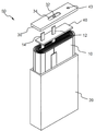
그 중 각형 전지의 일반적인 구조가 도 1에 개시되어 있다.The general structure of a prismatic battery among these is shown in Fig.
도 1을 참조하면, 각형 전지(50)는 젤리-롤형 전극조립체(10)가 각형 금속 케이스(20)에 내장되어 있고 케이스(20)의 개방 상단에 돌출형 전극단자(예를 들어, 음극단자: 32)가 형성되어 있는 탑 캡(30)이 결합되어 있는 구조로 이루어져 있다. 1, the
전극조립체(10)의 음극은 음극 탭(12)을 통해 탑 캡(30) 상의 음극단자(32)의 하단에 전기적으로 연결되며, 그러한 음극단자(32)는 절연부재(34)에 의해 탑 캡(30)으로부터 절연되어 있다. 반면에, 전극조립체(10)의 또 다른 전극(예를 들어, 양극)은 그것의 양극 탭(14)이 알루미늄, 스테인리스 스틸 등과 같은 도전성 소재로 되어 있는 탑 캡(30)에 전기적으로 연결되어 그 자체로서 양극단자를 형성한다. The negative electrode of the
또한, 전극 탭들(12, 14)을 제외하고 전극조립체(10)와 탑 캡(30)의 전기적 절연 상태를 보장하기 위하여, 각형 케이스(20)와 전극조립체(10) 사이에 시트형 절연부재(40)를 삽입한 뒤, 탑 캡(30)을 덮고, 탑 캡(30)과 케이스(20)의 접촉면을 따라서 용접으로 이들을 결합한다. 그런 다음, 전해액 주입구(43)를 통해 전해액을 주입한 후 용접하여 밀봉하고, 에폭시 등으로 용접 부위를 도포함으로써 전지가 제조된다.In order to ensure the electrical insulation between the
그러나, 최근에는 슬림한 타입 또는 다양한 디자인 트랜드로 인하여 새로운 형태의 전지셀이 요구되고 있는 실정이다. 구체적으로, 디바이스의 소형화 및 박형화에 따라서, 전지의 수납 공간이 충분한 여유를 갖지 못한 상태에서도 효율적인 구조로 장착될 수 있는 전지셀이 필요하다. However, in recent years, a new type of battery cell is required due to a slim type or various design trends. Specifically, in accordance with the miniaturization and thinning of the device, there is a need for a battery cell that can be mounted with an efficient structure even when the storage space of the battery does not have a sufficient margin.
또한, 종래의 디바이스는 대략 직육면체 형상으로 제조되었으나, 최근에는 다양한 형태의 외형을 가지는 구조의 디바이스가 개발되고 있는 바, 일반적으로 직육면체 또는 원통형으로 이루어진 전지셀의 경우, 상기와 같은 디바이스의 내부에 효율적으로 장착되기 어려운 경우가 발생하는 문제점이 있었다. Conventional devices have been manufactured in a substantially rectangular parallelepiped shape, but recently, devices having various external shapes have been developed. Generally, in the case of a battery cell having a rectangular parallelepiped shape or a cylindrical shape, It is difficult to be mounted to the vehicle.
예를 들어, 스마트 폰의 경우에는, 파지감의 향상을 위하여, 측면을 곡선 처리할 수 있다. 이렇게 곡선 처리된 부분을 가지도록 디자인된 디바이스의 경우, 직육면체 형상의 전지셀 또는 전지팩은 디바이스 내부의 공간 활용도에 한계가 있다는 문제가 있다. For example, in the case of a smart phone, the side can be curved in order to improve the grip feeling. In the case of a device designed to have such a curved portion, there is a problem that the battery cell or the battery pack having a rectangular parallelepiped shape has a limited space utilization inside the device.
즉, 곡선 처리된 부분에는 전지셀이 장착될 수 없는 사공간(dead space)이 형성되고, 이러한 사공간은 디바이스 부피 당 용량을 저하시키는 문제점을 발생시킨다. That is, a dead space is formed in the curved portion where the battery cell can not be mounted, and such a dead space causes a problem of lowering the capacity per device volume.
따라서, 다양한 구조의 디바이스에서도 사공간을 줄이고 용량을 극대화시켜서 장착 효율을 높일 수 있는 구조의 전지셀에 대한 필요성이 높은 실정이다.Therefore, there is a high need for a battery cell having a structure capable of increasing the installation efficiency by reducing the dead space and maximizing the capacity in devices having various structures.
본 발명은 상기와 같은 종래기술의 문제점과 과거로부터 요청되어온 기술적 과제를 해결하는 것을 목적으로 한다.SUMMARY OF THE INVENTION It is an object of the present invention to solve the above-described problems of the prior art and the technical problems required from the past.
구체적으로, 본 발명의 목적은 전지셀을 디바이스의 다양한 공간에 장착될 수 있도록 하는 구조로 설계하여, 디바이스의 내부 공간의 활용도를 극대화시키고, 일반적으로 장방형의 구조를 가지는 디바이스의 외형 구조에서 벗어나 여러가지 외형을 가지는 디바이스에서도 효율적으로 장착이 가능한 전지셀을 제공하는 것이다.More specifically, it is an object of the present invention to design a battery cell to be mounted in various spaces of a device to maximize the utilization of the internal space of the device, and to deviate from the external structure of a device having a generally rectangular structure, And to provide a battery cell that can be efficiently mounted even in a device having an external shape.
이러한 목적을 달성하기 위한 본 발명에 따른 전지셀은, 계단 구조의 전극조립체를 포함하는 전지셀로서, According to an aspect of the present invention, there is provided a battery cell including an electrode assembly having a stepped structure,
양극 시트, 음극 시트, 상기 음극 시트와 양극 시트의 사이에 개재되는 제 1 분리 시트, 및 상기 음극 시트 또는 양극 시트를 사이에 두고 상기 제 1 분리시트와 대면하는 제 2 분리 시트로 이루어진 조립 전극 시트를 포함하고, 상기 조립 전극 시트의 일단과 타단을 각각 권취한 구조의 제 1 전극 롤 및 제 2 전극 롤을 포함하며, 상기 제 1 전극 롤의 높이는 제 2 전극 롤의 높이보다 큰 구조로 형성되어 있는 전극조립체; 및An assembly electrode sheet comprising a positive electrode sheet, a negative electrode sheet, a first separating sheet interposed between the negative electrode sheet and the positive electrode sheet, and a second separating sheet facing the first separating sheet sandwiching the negative electrode sheet or the positive electrode sheet therebetween. And a first electrode roll and a second electrode roll having a structure in which one end and the other end of the assembled electrode sheet are wound, respectively, and the height of the first electrode roll is larger than the height of the second electrode roll An electrode assembly; And
상기 전극조립체의 외면에 대응하는 형상으로 이루어진 전지셀 케이스;A battery cell case having a shape corresponding to an outer surface of the electrode assembly;
를 포함하는 구조로 이루어질 수 있다. As shown in FIG.
따라서, 본 발명에 따른 전지셀은 상기와 같은 특정한 구조에 기반하여 다양한 용량 및 크기를 가진 전지셀로 제작될 수 있고, 이러한 전지셀을 장착하는 디바이스의 제조에 있어서, 전지셀이 디바이스의 다양한 공간에 효율적으로 장착될 수 있으므로, 디바이스 내부 공간 활용도를 극대화 시킬 수 있다. Therefore, the battery cell according to the present invention can be manufactured as a battery cell having various capacities and sizes based on the specific structure as described above. In the manufacture of the device for mounting the battery cell, It is possible to maximize the utilization of the space inside the device.
또한, 상기 전지셀 케이스가 상기 전극조립체의 외면에 대응하는 형상으로 이루어져 있으므로, 전지용량을 증대시킴과 동시에 콤팩트 한 구조로 잉여 공간의 활용도를 향상시킬 수 있다.In addition, since the battery cell case has a shape corresponding to the outer surface of the electrode assembly, the battery capacity can be increased and the utilization of the surplus space can be improved with a compact structure.
하나의 구체적인 예에서, 상기 전극조립체에서 제 2 전극 롤은 제 1 전극 롤의 측면 방향으로 배열되는 구조일 수 있다. 따라서, 상기 제 1 전극 롤 및 제 2 전극 롤이 배열되어 전극조립체를 형성할 때, 상기 전극조립체는 제 1 전극 롤 및 제 2 전극 롤의 높이 차이에 의해서 계단 구조가 형성될 수 있다.In one specific example, the second electrode roll in the electrode assembly may be arranged in the lateral direction of the first electrode roll. Therefore, when the first electrode roll and the second electrode roll are arranged to form an electrode assembly, the electrode assembly may have a stepped structure by a height difference between the first electrode roll and the second electrode roll.
또한, 상기 전극조립체에서 제 2 전극 롤은 제 1 전극 롤의 수직 방향으로 적층되는 구조일 수 도 있다. 이 경우, 제 2 전극 롤은 제 1 전극 롤과 비교하여 평면상으로 다른 형상으로 형성될 수 있다. 예를 들어, 제 2 전극 롤의 평면상의 길이 및 폭 중 적어도 하나가 제 1 전극 롤의 길이 또는 폭 보다 작은 구조로 형성되어 있어서, 제 1 전극 롤에 제 2 전극 롤을 수직 방향으로 적층하였을 때, 계단 구조를 형성하는 구조로 이루어질 수 있다. In addition, the second electrode roll in the electrode assembly may be a structure in which the first electrode roll is stacked in the vertical direction. In this case, the second electrode roll may be formed in a different shape in plan view as compared with the first electrode roll. For example, when at least one of the length and the width on the plane of the second electrode roll is formed to be smaller than the length or the width of the first electrode roll, when the second electrode roll is vertically stacked on the first electrode roll , And a structure for forming a stepped structure.
앞서 언급한 바와 같이 상기 제 1 전극 롤의 높이는 상기 제 2 전극 롤의 높이보다 큰 구조로 이루어질 수 있으며, 이러한 구조는, 예를 들어 상기 제 1 전극 롤의 권취 폭을 상기 제 2 전극 롤의 권취 폭보다 큰 구조로 형성함으로써 달성될 수 있다. 구체적인 예로, 상기 제 1 전극 롤의 높이는 제 2 전극 롤의 높이의 20% 내지 95%의 범위, 바람직하게는 30 내지 90%의 범위일 수 있다. 또한, 상기 제 1 전극 롤의 권취 폭은 제 2 전극 롤의 권취 폭의 20% 내지 95%의 범위, 바람직하게는 30 내지 90%의 범위일 수 있다.As described above, the height of the first electrode roll may be larger than the height of the second electrode roll. For example, the width of the first electrode roll may be greater than the width of the second electrode roll Width of the first electrode layer. As a specific example, the height of the first electrode roll may be in the range of 20% to 95% of the height of the second electrode roll, preferably in the range of 30% to 90%. The winding width of the first electrode roll may be in the range of 20% to 95%, preferably in the range of 30% to 90% of the winding width of the second electrode roll.
상기와 같이 제 1 전극 롤의 권취 폭이 제 2 전극 롤의 권취 폭보다 큰 구조는, 예를 들어 상기 제 1 전극 롤의 권취 횟수가 상기 제 2 전극 롤의 권취 횟수보다 많은 구조로 형성함으로써 달성 가능하다. As described above, the structure in which the winding width of the first electrode roll is larger than the winding width of the second electrode roll can be achieved, for example, by forming the structure in which the number of windings of the first electrode roll is larger than the number of windings of the second electrode roll It is possible.
상기 제 1 전극 롤 및 제 2 전극 롤은 각각 수직 단면상으로 원형 또는 타원형으로 권취될 수 있다. 상기와 같이 타원형으로 권취되는 전극 롤은 조립 전극 시트를 수직 단면 상으로 원형으로 권취한 후 압박하는 과정을 통해 제조될 수도 있다.The first electrode roll and the second electrode roll may be respectively wound in a circular or elliptical shape in a vertical section. The electrode rolls wound in the elliptical shape as described above may be manufactured by winding the assembled electrode sheet in a circular shape in a vertical section and then pressing it.
이러한 구조에 관한 첫번째 예에서, 상기 제 1 전극 롤 및 제 2 전극 롤은 각각 수직 단면상으로 타원형이고, 상기 제 1 전극 롤의 단축 길이는 제 2 전극 롤의 단축 길이 보다 큰 구조로 형성될 수 있다. 이 때, 상기 제 1 전극 롤의 단축 길이는 제 2 전극 롤의 단축 길이의 20% 내지 95%의 범위, 바람직하게는 30 내지 90%의 범위일 수 있다.In the first example of this structure, the first electrode roll and the second electrode roll may each be elliptical in vertical section, and the minor axis length of the first electrode roll may be larger than the minor axis length of the second electrode roll . In this case, the minor axis length of the first electrode roll may be in the range of 20% to 95%, preferably 30 to 90% of the minor axis length of the second electrode roll.
두번째 예에서, 상기 제 1 전극 롤 및 제 2 전극 롤은 각각 수직 단면상으로 원형이고, 상기 제 1 전극 롤의 반경은 제 2 전극 롤의 반경보다 큰 구조로 형성될 수 있다. 이 때, 상기 제 1 전극 롤의 반경은 제 2 전극 롤의 반경의 20% 내지 95%의 범위, 바람직하게는 30 내지 90%의 범위일 수 있다.In the second example, the first electrode roll and the second electrode roll may each be circular in a vertical section, and the radius of the first electrode roll may be larger than the radius of the second electrode roll. At this time, the radius of the first electrode roll may be in the range of 20% to 95%, preferably in the range of 30% to 90% of the radius of the second electrode roll.
세번째 예에서, 수직 단면 상으로, 상기 제 1 전극 롤은 원형이고 제 2 전극 롤은 타원형이며, 상기 제 1 전극 롤의 직경은 제 2 전극 롤의 단축 길이보다 큰 구조로 형성될 수 있다. 이 때, 상기 제 1 전극 롤의 직경은 제 2 전극 롤의 단축 길이의 20% 내지 95%의 범위, 바람직하게는 30 내지 90%의 범위일 수 있다.In the third example, the first electrode roll is circular, the second electrode roll is elliptical, and the diameter of the first electrode roll is larger than the short axis length of the second electrode roll. In this case, the diameter of the first electrode roll may be in the range of 20% to 95%, preferably 30 to 90% of the minor axis length of the second electrode roll.
하나의 구체적인 예에서, 상기 제 1 전극 롤의 하단과 제 2 전극 롤의 하단은 평면상으로 일직선 상에 위치하는 구조일 수 있다. 이러한 구조의 전극조립체를 전지셀 케이스에 수납하였을 때, 상기 제 1 전극 롤 및 제 2 전극 롤의 높이 차이에 따라서, 상기 전지셀 케이스의 상부에만 계단 구조가 형성되는 구조일 수 있다. In one specific example, the lower end of the first electrode roll and the lower end of the second electrode roll may be arranged in a straight line on a plane. When the electrode assembly having such a structure is housed in the battery cell case, the step structure may be formed only on the upper portion of the battery cell case according to the height difference between the first electrode roll and the second electrode roll.
한편, 상기 제 1 전극 롤 및 제 2 전극 롤은 조립 전극 시트가 각각 시계방향 또는 반시계 방향으로 권취됨으로써 형성될 수 있다. 즉, 상기 제 1 전극 롤 및 제 2 전극 롤은 상기 조립 전극 시트가 서로 같은 방향으로 권취되어 형성될 수 있지만, 서로 다른 방향으로도 권취되어 형성될 수 있다. 구체적으로, 상기 제 1 전극 롤 및 제 2 전극 롤은 모두 조립 전극 시트가 시계 방향으로 권취되거나, 또는 이들이 모두 반시계 방향으로 권취될 수 있다. 또한, 상기 제 1 전극 롤 및 제 2 전극 롤 중 하나의 전극 롤은 시계 방향으로 권취되어 있는 구조이고, 다른 전극 롤은 반시계 방향으로 권취되어 있는 구조일 수 도 있다. Meanwhile, the first electrode roll and the second electrode roll may be formed by winding the assembled electrode sheet in a clockwise or counterclockwise direction, respectively. That is, the first electrode roll and the second electrode roll may be formed by winding the assembled electrode sheets in the same direction, but may also be wound in different directions. Concretely, both the first electrode roll and the second electrode roll can be wound in a clockwise direction or both in a counterclockwise direction. In addition, one of the electrode rolls of the first electrode roll and the second electrode roll is wound clockwise, and the other electrode roll may be wound in a counterclockwise direction.
본 발명에 따른 조립 전극 시트는, 평면을 기준으로 높이 방향으로 제 2 분리 시트, 음극 시트, 제 1 분리 시트 및 양극 시트가 순서대로 적층되어 있거나, 또는 제 2 분리 시트, 양극 시트, 제 1 분리 시트 및 음극 시트가 순서대로 적층되어 있는 구조일 수 있다. 이러한 조립 전극 시트의 일단 및 타단을 각각 권취하여 제 1 전극 롤 및 제 2 전극 롤을 제조할 수 있다.The assembled electrode sheet according to the present invention is characterized in that the second separator sheet, the negative electrode sheet, the first separator sheet and the positive electrode sheet are stacked in order in the height direction with respect to the plane, or the second separator sheet, A sheet and a negative electrode sheet may be stacked in this order. The first electrode roll and the second electrode roll can be manufactured by winding one end and the other end of the assembled electrode sheet, respectively.
이 때, 상기 제 1 전극 롤 및 제 2 전극 롤 중 적어도 하나는 제 2 분리 시트가 외측을 향하도록 권취될 수 있다. 이러한 구조의 전극 롤은 최외곽에 제 2 분리 시트가 위치하게 되고, 따라서 상기 제 2 분리 시트에 의해 내측에 위치하는 양극 시트 또는 음극 시트를 전극 롤 외부로부터 보호하는 구조로 형성될 수 있다.At this time, at least one of the first electrode roll and the second electrode roll may be wound such that the second separator sheet faces outward. The electrode roll having such a structure may be formed with a structure in which the second separation sheet is located at the outermost periphery, and thus the positive electrode sheet or the negative electrode sheet positioned inside by the second separation sheet is protected from the outside of the electrode roll.
상기 제 2 분리 시트가 외측을 향하도록 권취되어 있는 전극 롤의 최외곽의 양극 시트 또는 음극 시트에는 제 1 분리 시트와 대면하는 면에만 활물질이 도포될 수 있다.The active material may be applied only to the surface of the positive electrode sheet or negative electrode sheet at the outermost side of the electrode roll wound with the second separator sheet facing outwardly, only on the surface facing the first separator sheet.
또한, 상기 제 1 전극 롤 및 제 2 전극 롤 중 적어도 하나는 제 2 분리 시트가 내측을 향하도록 권취될 수 있다. 이 경우, 상기 제 2 분리 시트가 내측을 향하도록 권취되어 있는 전극 롤의 최외곽의 양극 시트 또는 음극 시트에는 그것의 내측에 접하는 제 1 분리 시트와 대면하는 면에만 활물질이 도포될 수 있다. At least one of the first electrode roll and the second electrode roll may be wound such that the second separator sheet faces inward. In this case, the active material may be applied only to the surface of the positive electrode sheet or the negative electrode sheet of the outermost electrode roll wound so that the second separator sheet faces inward, on the surface facing the first separator sheet in contact with the inside thereof.
상기 전지셀 케이스는, 수지층과 금속층을 포함하는 라미네이트 시트의 전지 케이스일 수 있고, 또는, 각형 전지에 사용되는 금속 캔일 수 있다. The battery cell case may be a battery case of a laminate sheet including a resin layer and a metal layer, or may be a metal can used for a prismatic battery.
상기 라미네이트 시트의 전지 케이스와 금속 캔에는, 본 발명에 따른 계단 구조의 전극조립체가 내장되는 수납부가 형성되어 있을 수 있으며, 상기 수납부는 본 발명에 따른 계단 구조의 전극조립체의 형상에 대응하는 폭과 높이가 있는 계단 구조의 형상을 가질 수 있다.The battery case and the metal can of the laminate sheet may be formed with a housing portion in which the electrode assembly having the stepped structure according to the present invention is embedded. The housing portion may have a width corresponding to the shape of the electrode assembly of the step structure according to the present invention It may have a shape of a stepped structure having a height.
상기 전지셀은 리튬이온 전지셀 또는 리튬이온 폴리머 전지셀일 수 있지만, 이들만으로 한정되지 않음은 물론이다.The battery cell may be a lithium ion battery cell or a lithium ion polymer battery cell, but is not limited thereto.
본 발명은 또한, 상기 전지셀을 전원으로 포함하고 있는 디바이스를 제공하는 바, 상기 디바이스는 휴대폰, 휴대용 컴퓨터, 스마트폰, 태플릿 PC, 스마트 패드, 넷북, LEV(Light Electronic Vehicle), 전기자동차, 하이브리드 전기자동차, 플러그-인 하이브리드 전기자동차, 및 전력저장장치 등으로부터 선택되는 것일 수 있다. The present invention also provides a device comprising the battery cell as a power source, wherein the device is used in a mobile phone, a portable computer, a smart phone, a tablet PC, a smart pad, a netbook, a LEV (Light Electronic Vehicle) A hybrid electric vehicle, a plug-in hybrid electric vehicle, and a power storage device.
이들 디바이스의 구조 및 그것의 제작 방법은 당 업계에 공지되어 있으므로, 본 명세서에서는 그에 대한 자세한 설명은 생략한다.The structure of these devices and their fabrication methods are well known in the art, and a detailed description thereof will be omitted herein.
이상에서 설명한 바와 같이, 본 발명에 따른 전지셀은 계단 구조를 형성시킴으로써, 전지셀의 장착 공간 확보를 용이하게 하고, 디바이스 내부의 사공간을 활용하여 공간 활용도를 극대화 시킬 수 있을 뿐만 아니라, 디바이스에 고용량의 전지셀 사용이 가능하며, 디바이스를 더욱 소형화 시키는 효과를 제공한다. As described above, since the battery cell according to the present invention has a stepped structure, it is possible to easily secure the mounting space of the battery cell, maximize the space utilization by utilizing the dead space inside the device, It is possible to use a high-capacity battery cell, and it is possible to further miniaturize the device.
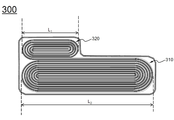
도 1은 종래의 대표적인 각형 전지의 분해 사시도이다;
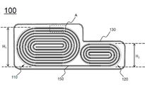
도 2는 본 발명의 하나의 실시예에 따른 전지셀의 수직 단면도이다;
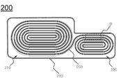
도 3은 본 발명의 또 다른 실시예에 따른 전지셀의 수직 단면도이다;
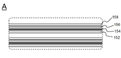
도 4는 도 2의 A 부위에 관한 확대도이다;
도 5는 도 3의 B 부위에 관한 확대도이다;
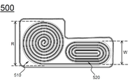
도 6 내지 도 9는 본 발명의 또 다른 실시예에 따른 전지셀의 수직 단면도들이다.1 is an exploded perspective view of a typical conventional prismatic battery;
2 is a vertical cross-sectional view of a battery cell according to one embodiment of the present invention;
3 is a vertical cross-sectional view of a battery cell according to another embodiment of the present invention;
Fig. 4 is an enlarged view of part A in Fig. 2; Fig.
5 is an enlarged view of the region B in Fig. 3; Fig.
6 to 9 are vertical sectional views of a battery cell according to another embodiment of the present invention.
이하에서는, 본 발명의 실시예에 따른 도면을 참조하여 설명하지만, 이는 본 발명의 더욱 용이한 이해를 위한 것으로, 본 발명의 범주가 그것에 의해 한정되는 것은 아니다.Hereinafter, embodiments of the present invention will be described with reference to the accompanying drawings, but the present invention is not limited by the scope of the present invention.
본 명세서에서는 설명의 편의를 위하여 일반적으로 전지셀에 포함되는 전극 단자, 보호회로 등은 생략하였다. In this specification, for convenience of explanation, the electrode terminals and the protection circuit included in the battery cell are omitted.
도 2에는 본 발명의 하나의 실시예에 따른 전지셀의 수직 단면도가 도시되어 있다. 2 is a vertical sectional view of a battery cell according to an embodiment of the present invention.
도 2를 참조하면, 전지셀(100)은 제 1 전극 롤(110) 및 제 2 전극 롤(120)을 포함하는 전극조립체, 및 전극조립체를 수납하는 전지셀 케이스(130)를 포함하는 구조로 구성되어 있다. 2, the
제 1 전극 롤(110) 및 제 2 전극 롤(120)은 양극 시트, 제 1 분리 시트, 음극 시트, 및 제 2 분리 시트가 적층된 조립 전극 시트(150)의 일단과 타단을 각각 권취하여 제조된 구조로 이루어져 있고, 제 1 전극 롤(110) 및 제 2 전극 롤(120)은 서로 측면 방향으로 배열되어 있으며, 제 1 전극 롤(110)의 높이(H1)는 제 2 전극 롤(120)의 높이(H2)보다 큰 구조로 형성되어 있다. 따라서 제 1 전극 롤(110)과 제 2 전극 롤(120)의 높이 차이에 의해 계단 구조가 형성된다. The
제 1 전극 롤(110)의 하단과 제 2 전극 롤(120)의 하단은 평면상으로 일직선 상에 위치하고 있어서, 제 1 전극 롤(110)과 제 2 전극 롤(120)의 높이 차이에 의해 계단 구조는 전지셀(100)의 상부에만 형성되어 있다. The lower end of the
제 1 전극 롤(110) 및 제 2 전극 롤(120)은, 수직 단면상으로 대략 타원형으로 권취된 구조로 이루어져 있으며, 제 1 전극 롤(110)은 조립 전극 시트(150)의 일단이 반시계 방향으로 권취된 구조로 형성되어 있고, 제 2 전극 롤은 조립 전극 시트(150)의 타단이 시계 방향으로 권취된 구조로 형성되어 있다. The
전지셀 케이스(130)는 제 1 전극 롤(110) 및 제 2 전극 롤(120)이 효율적으로 장착되도록, 전극조립체의 형상에 대응하여 계단 구조의 형상을 포함하고 있다. The
도 3에는 본 발명의 또 다른 실시예에 따른 전지셀의 수직 단면도가 도시되어 있다.3 is a vertical cross-sectional view of a battery cell according to another embodiment of the present invention.
도 3을 참조하면, 전지셀(200)은 제 1 전극 롤(210), 제 2 전극 롤(220), 및 전지셀 케이스(230)를 포함하며, 도 1의 전지셀(100)과는 달리, 제 1 전극 롤(210) 및 제 2 전극 롤(220)은 모두 조립 전극 시트(250)가 반시계 방향으로 권취된 구조로 형성되어 있다. 3, the
제 1 전극 롤(210) 및 제 2 전극 롤(220)의 권취 방향이 서로 반대인 구조에 의하여, 제 1 전극 롤(210)을 구성하는 조립 전극 시트(250)의 최외곽 부위의 하단은 제 2 전극 롤(220)을 구성하는 조립 전극 시트(250)의 최외각 부위의 상단과 연결되어 있다.The lower end of the outermost portion of the assembled
도 4는 도 2의 A 부위에 관한 확대도로서, 도 4를 도 2와 함께 참조하면, 제 1 전극 롤(110)을 구성하는 조립 전극 시트(150)는 평면을 기준으로 높이 방향으로 양극 시트(152), 제 1 분리 시트(154), 음극 시트(156), 및 제 2 분리 시트(158)가 순서대로 적층되어 있다. 최외곽에 위치하는 제 2 분리 시트(158)는 내측에 위치하는 양극 시트(152) 또는 음극 시트(156)를 전극 롤 외부로부터 보호하는 구조로 형성되어 있다. 또한, 제 2 분리 시트(158)와 인접한 음극 시트(156)에는 제 1 분리 시트(154)와 대면하는 면에만 활물질이 도포되어 있다. Referring to Fig. 4 and Fig. 2, an assembled
도 5는 도 3의 B 부위에 관한 확대도로서, 도 5를 도 3과 함께 참조하면, 제 2 전극 롤(220)을 구성하는 조립 전극 시트(250)는 제 2 분리 시트(258), 양극 시트(256), 제 1 분리 시트(254), 음극 시트(252)가 순서대로 적층되어 있으며, 최외곽의 음극 시트(252)는 제 1 분리 시트(256)를 사이에 두고 양극 시트(256)와 대면하는 면에만 활물질이 도포되어 있다. 5, the assembled
도 6 내지 도 9에는 본 발명의 또 다른 실시예에 따른 전지셀의 수직 단면도들이 도시되어 있다.6 to 9 are vertical sectional views of a battery cell according to another embodiment of the present invention.
먼저 도 6 및 도 7을 참조하면, 제 2 전극 롤(320, 320’)은 제 1 전극 롤(310, 310’)의 수직 방향으로 적층된 구조를 형성하고 있다. 제 2 전극 롤(320, 320’)의 길이(L1)는 제 1 전극 롤(320, 320’)의 길이(L2) 보다 작은 구조로 형성되어 있어서, 제 1 전극 롤(310, 310’)에 제 2 전극 롤(320, 320’)을 수직 방향으로 적층하였을 때, 계단 구조를 형성하고 있다. 도 6에는 계단 구조가 우측에 형성된 구조의 전지셀(300)이 도시되어 있고, 도 7에는 계단 구조가 양측에 형성된 구조의 전지셀(300’)가 도시되어 있다. 도면에는 도시되어 있지 않지만, 제 2 전극 롤의 위치에 따라서 계단 구조가 좌측에 형성된 구조로도 형성될 수 있음은 물론이다.Referring first to FIGS. 6 and 7, the second electrode rolls 320 and 320 'form a stacked structure in the vertical direction of the first electrode rolls 310 and 310'. The length L 1 of the second electrode rolls 320 and 320 'is smaller than the length L 2 of the first electrode rolls 320 and 320' so that the first electrode rolls 310 and 310 ' The second electrode rolls 320 and 320 'are stacked in the vertical direction to form a stepped structure. FIG. 6 shows a
도 8을 참조하면, 전지셀(400)은 제 1 전극 롤(410) 및 제 2 전극 롤(420)은 각각 수직 단면상으로 원형으로 이루어져 있고, 제 1 전극 롤(410)의 반경(r1)은 제 2 전극 롤(420)의 반경(r2)보다 큰 구조로 형성되어 계단 구조를 이루고 있다. Referring to FIG. 8, the
또한, 도 9를 참조하면, 전지셀(500)은 수직 단면상으로 제 1 전극 롤(510)은 원형 구조로 이루어져 있고, 제 2 전극 롤(520)은 타원형 구조로 이루어져 있으며, 제 1 전극 롤(510)의 직경(R)은 제 2 전극 롤(520)의 단축 길이(W)보다 큰 구조로 형성되어 계단 구조를 이루고 있다.
9, the
본 발명이 속한 분야에서 통상의 지식을 가진 자라면 상기 내용을 바탕으로 본 발명의 범주 내에서 다양한 응용 및 변형을 행하는 것이 가능할 것이다. Those skilled in the art will appreciate that various modifications, additions and substitutions are possible, without departing from the scope and spirit of the invention as disclosed in the accompanying claims.
Claims (21)
상기 전극조립체의 외면에 대응하는 형상으로 이루어진 전지셀 케이스;
를 포함하는 것을 특징으로 하는 전지셀.An assembly electrode sheet comprising a positive electrode sheet, a negative electrode sheet, a first separating sheet interposed between the negative electrode sheet and the positive electrode sheet, and a second separating sheet facing the first separating sheet sandwiching the negative electrode sheet or the positive electrode sheet therebetween. And a first electrode roll and a second electrode roll having a structure in which one end and the other end of the assembled electrode sheet are wound, respectively, and the height of the first electrode roll is larger than the height of the second electrode roll An electrode assembly; And
A battery cell case having a shape corresponding to an outer surface of the electrode assembly;
The battery cell comprising:
Applications Claiming Priority (2)
| Application Number | Priority Date | Filing Date | Title |
|---|---|---|---|
| KR20130022623 | 2013-03-04 | ||
| KR1020130022623 | 2013-03-04 |
Publications (2)
| Publication Number | Publication Date |
|---|---|
| KR20140109280A true KR20140109280A (en) | 2014-09-15 |
| KR101462043B1 KR101462043B1 (en) | 2014-11-18 |
Family
ID=51755983
Family Applications (1)
| Application Number | Title | Priority Date | Filing Date |
|---|---|---|---|
| KR1020140023211A Active KR101462043B1 (en) | 2013-03-04 | 2014-02-27 | Battery Cell Having Electrode Assembly of Stair-like Structure |
Country Status (1)
| Country | Link |
|---|---|
| KR (1) | KR101462043B1 (en) |
Cited By (2)
| Publication number | Priority date | Publication date | Assignee | Title |
|---|---|---|---|---|
| JP2020205241A (en) * | 2019-05-21 | 2020-12-24 | 寧徳新能源科技有限公司Ningde Amperex Technology Limited | Battery cell assembly and electrochemical device |
| WO2023060713A1 (en) * | 2021-10-12 | 2023-04-20 | 宁德时代新能源科技股份有限公司 | Battery cell, battery, electric device, method for preparing battery, and device |
Families Citing this family (1)
| Publication number | Priority date | Publication date | Assignee | Title |
|---|---|---|---|---|
| KR101950464B1 (en) | 2015-11-30 | 2019-02-20 | 주식회사 엘지화학 | Battery Cell of Irregular Structure with Improved Sealing Reliability of Cell Case |
Family Cites Families (3)
| Publication number | Priority date | Publication date | Assignee | Title |
|---|---|---|---|---|
| JP3611765B2 (en) * | 1999-12-09 | 2005-01-19 | シャープ株式会社 | Secondary battery and electronic device using the same |
| KR100440934B1 (en) * | 2002-02-06 | 2004-07-21 | 삼성에스디아이 주식회사 | Secondary battery |
| JP3680797B2 (en) * | 2002-02-08 | 2005-08-10 | 日本電池株式会社 | Non-aqueous electrolyte battery |
-
2014
- 2014-02-27 KR KR1020140023211A patent/KR101462043B1/en active Active
Cited By (3)
| Publication number | Priority date | Publication date | Assignee | Title |
|---|---|---|---|---|
| JP2020205241A (en) * | 2019-05-21 | 2020-12-24 | 寧徳新能源科技有限公司Ningde Amperex Technology Limited | Battery cell assembly and electrochemical device |
| WO2023060713A1 (en) * | 2021-10-12 | 2023-04-20 | 宁德时代新能源科技股份有限公司 | Battery cell, battery, electric device, method for preparing battery, and device |
| CN116802878A (en) * | 2021-10-12 | 2023-09-22 | 宁德时代新能源科技股份有限公司 | Battery cells, batteries, electrical equipment, methods and equipment for preparing batteries |
Also Published As
| Publication number | Publication date |
|---|---|
| KR101462043B1 (en) | 2014-11-18 |
Similar Documents
| Publication | Publication Date | Title |
|---|---|---|
| KR101572836B1 (en) | Battery Cell Having Structure of Steps-Formed | |
| KR101573691B1 (en) | Battery Cell Provided With Cut Portion and Battery Pack Comprising The Same | |
| KR101586201B1 (en) | Battery Cell Having Electrode Assembly Of Staggered Array Structure | |
| KR101402657B1 (en) | Battery Pack of Irregular Structure | |
| KR101526457B1 (en) | Electrode Having Round Corner | |
| JP6340431B2 (en) | Battery cell including asymmetric structure and bay structure | |
| US20150037664A1 (en) | Battery cell of irregular structure and battery module employed with the same | |
| KR20150032971A (en) | Battery Cell Having Jelly-Roll Type Electrode Assembly of Steps-Formed Structure | |
| KR20160041247A (en) | Battery Cell Comprising Battery Case of Shape Corresponding to Electrode Assembly of Stair-like Structure | |
| KR101580086B1 (en) | Electrode Assembly of Combination Structure | |
| KR101675939B1 (en) | Battery Cell Having Electrode Assembly of Steps-Formed Structure | |
| KR101606752B1 (en) | Method for Production of Jelly-Roll Type Electrode Assembly of Steps-Formed Structure | |
| KR101462043B1 (en) | Battery Cell Having Electrode Assembly of Stair-like Structure | |
| CN107369853B (en) | Electrochemical energy storage device | |
| KR101876614B1 (en) | Electrode Assembly of Combination Structure | |
| KR101809142B1 (en) | Electrode Assembly Including Electrodes Being Interconnected | |
| KR20140110124A (en) | Winding-typed Electrode Assembly of Stair Structure | |
| KR20150045078A (en) | Battery Cell Having Mixed Structure | |
| KR20050096403A (en) | Secondary battery |
Legal Events
| Date | Code | Title | Description |
|---|---|---|---|
| A201 | Request for examination | ||
| PA0109 | Patent application |
St.27 status event code: A-0-1-A10-A12-nap-PA0109 |
|
| PA0201 | Request for examination |
St.27 status event code: A-1-2-D10-D11-exm-PA0201 |
|
| A302 | Request for accelerated examination | ||
| PA0302 | Request for accelerated examination |
St.27 status event code: A-1-2-D10-D17-exm-PA0302 St.27 status event code: A-1-2-D10-D16-exm-PA0302 |
|
| D13-X000 | Search requested |
St.27 status event code: A-1-2-D10-D13-srh-X000 |
|
| D14-X000 | Search report completed |
St.27 status event code: A-1-2-D10-D14-srh-X000 |
|
| E902 | Notification of reason for refusal | ||
| PE0902 | Notice of grounds for rejection |
St.27 status event code: A-1-2-D10-D21-exm-PE0902 |
|
| E701 | Decision to grant or registration of patent right | ||
| PE0701 | Decision of registration |
St.27 status event code: A-1-2-D10-D22-exm-PE0701 |
|
| PG1501 | Laying open of application |
St.27 status event code: A-1-1-Q10-Q12-nap-PG1501 |
|
| GRNT | Written decision to grant | ||
| PR0701 | Registration of establishment |
St.27 status event code: A-2-4-F10-F11-exm-PR0701 |
|
| PR1002 | Payment of registration fee |
St.27 status event code: A-2-2-U10-U11-oth-PR1002 Fee payment year number: 1 |
|
| PG1601 | Publication of registration |
St.27 status event code: A-4-4-Q10-Q13-nap-PG1601 |
|
| PN2301 | Change of applicant |
St.27 status event code: A-5-5-R10-R13-asn-PN2301 St.27 status event code: A-5-5-R10-R11-asn-PN2301 |
|
| R18-X000 | Changes to party contact information recorded |
St.27 status event code: A-5-5-R10-R18-oth-X000 |
|
| P22-X000 | Classification modified |
St.27 status event code: A-4-4-P10-P22-nap-X000 |
|
| FPAY | Annual fee payment |
Payment date: 20170919 Year of fee payment: 4 |
|
| PR1001 | Payment of annual fee |
St.27 status event code: A-4-4-U10-U11-oth-PR1001 Fee payment year number: 4 |
|
| R17-X000 | Change to representative recorded |
St.27 status event code: A-5-5-R10-R17-oth-X000 |
|
| FPAY | Annual fee payment |
Payment date: 20181016 Year of fee payment: 5 |
|
| PR1001 | Payment of annual fee |
St.27 status event code: A-4-4-U10-U11-oth-PR1001 Fee payment year number: 5 |
|
| R18-X000 | Changes to party contact information recorded |
St.27 status event code: A-5-5-R10-R18-oth-X000 |
|
| R18-X000 | Changes to party contact information recorded |
St.27 status event code: A-5-5-R10-R18-oth-X000 |
|
| R18-X000 | Changes to party contact information recorded |
St.27 status event code: A-5-5-R10-R18-oth-X000 |
|
| FPAY | Annual fee payment |
Payment date: 20191016 Year of fee payment: 6 |
|
| PR1001 | Payment of annual fee |
St.27 status event code: A-4-4-U10-U11-oth-PR1001 Fee payment year number: 6 |
|
| PR1001 | Payment of annual fee |
St.27 status event code: A-4-4-U10-U11-oth-PR1001 Fee payment year number: 7 |
|
| PN2301 | Change of applicant |
St.27 status event code: A-5-5-R10-R11-asn-PN2301 |
|
| PN2301 | Change of applicant |
St.27 status event code: A-5-5-R10-R14-asn-PN2301 |
|
| PR1001 | Payment of annual fee |
St.27 status event code: A-4-4-U10-U11-oth-PR1001 Fee payment year number: 8 |
|
| P22-X000 | Classification modified |
St.27 status event code: A-4-4-P10-P22-nap-X000 |
|
| PR1001 | Payment of annual fee |
St.27 status event code: A-4-4-U10-U11-oth-PR1001 Fee payment year number: 9 |
|
| PR1001 | Payment of annual fee |
St.27 status event code: A-4-4-U10-U11-oth-PR1001 Fee payment year number: 10 |
|
| PR1001 | Payment of annual fee |
St.27 status event code: A-4-4-U10-U11-oth-PR1001 Fee payment year number: 11 |
|
| PR1001 | Payment of annual fee |
St.27 status event code: A-4-4-U10-U11-oth-PR1001 Fee payment year number: 12 |
|
| U11 | Full renewal or maintenance fee paid |
Free format text: ST27 STATUS EVENT CODE: A-4-4-U10-U11-OTH-PR1001 (AS PROVIDED BY THE NATIONAL OFFICE) Year of fee payment: 12 |