EP4254334A2 - System and method for valve quantification - Google Patents
System and method for valve quantification Download PDFInfo
- Publication number
- EP4254334A2 EP4254334A2 EP23191949.9A EP23191949A EP4254334A2 EP 4254334 A2 EP4254334 A2 EP 4254334A2 EP 23191949 A EP23191949 A EP 23191949A EP 4254334 A2 EP4254334 A2 EP 4254334A2
- Authority
- EP
- European Patent Office
- Prior art keywords
- computer
- valve annulus
- organ
- measurements
- heart
- Prior art date
- Legal status (The legal status is an assumption and is not a legal conclusion. Google has not performed a legal analysis and makes no representation as to the accuracy of the status listed.)
- Pending
Links
- 238000000034 method Methods 0.000 title claims abstract description 117
- 238000011002 quantification Methods 0.000 title description 14
- 238000005259 measurement Methods 0.000 claims abstract description 75
- 210000003484 anatomy Anatomy 0.000 claims abstract description 39
- 210000000056 organ Anatomy 0.000 claims abstract description 25
- 238000012800 visualization Methods 0.000 claims abstract description 8
- 210000004115 mitral valve Anatomy 0.000 claims description 114
- 210000003540 papillary muscle Anatomy 0.000 claims description 28
- 239000008280 blood Substances 0.000 claims description 19
- 210000004369 blood Anatomy 0.000 claims description 19
- 210000005246 left atrium Anatomy 0.000 claims description 12
- 238000013507 mapping Methods 0.000 claims description 6
- 230000002861 ventricular Effects 0.000 claims description 5
- 210000003102 pulmonary valve Anatomy 0.000 claims description 3
- 230000008569 process Effects 0.000 description 43
- 239000007943 implant Substances 0.000 description 29
- 238000004458 analytical method Methods 0.000 description 25
- 230000006870 function Effects 0.000 description 18
- 238000012545 processing Methods 0.000 description 16
- 238000013500 data storage Methods 0.000 description 9
- 210000005240 left ventricle Anatomy 0.000 description 9
- 230000008439 repair process Effects 0.000 description 9
- 230000000007 visual effect Effects 0.000 description 7
- 230000017531 blood circulation Effects 0.000 description 6
- 238000010586 diagram Methods 0.000 description 6
- 238000002513 implantation Methods 0.000 description 5
- 210000005241 right ventricle Anatomy 0.000 description 5
- 238000001356 surgical procedure Methods 0.000 description 5
- 206010027727 Mitral valve incompetence Diseases 0.000 description 4
- 238000005516 engineering process Methods 0.000 description 4
- 210000005245 right atrium Anatomy 0.000 description 4
- 210000000709 aorta Anatomy 0.000 description 3
- 239000002872 contrast media Substances 0.000 description 3
- 238000002059 diagnostic imaging Methods 0.000 description 3
- 210000002837 heart atrium Anatomy 0.000 description 3
- 238000004513 sizing Methods 0.000 description 3
- 208000001910 Ventricular Heart Septal Defects Diseases 0.000 description 2
- 230000001746 atrial effect Effects 0.000 description 2
- 230000036772 blood pressure Effects 0.000 description 2
- 238000004364 calculation method Methods 0.000 description 2
- 238000005520 cutting process Methods 0.000 description 2
- 230000006378 damage Effects 0.000 description 2
- 238000013461 design Methods 0.000 description 2
- 208000037265 diseases, disorders, signs and symptoms Diseases 0.000 description 2
- 208000035475 disorder Diseases 0.000 description 2
- 238000003384 imaging method Methods 0.000 description 2
- 210000004165 myocardium Anatomy 0.000 description 2
- 238000005457 optimization Methods 0.000 description 2
- 239000003826 tablet Substances 0.000 description 2
- VYZAMTAEIAYCRO-UHFFFAOYSA-N Chromium Chemical compound [Cr] VYZAMTAEIAYCRO-UHFFFAOYSA-N 0.000 description 1
- 208000002330 Congenital Heart Defects Diseases 0.000 description 1
- 241000699670 Mus sp. Species 0.000 description 1
- 208000006396 Pulmonary artery stenosis Diseases 0.000 description 1
- 230000005856 abnormality Effects 0.000 description 1
- 208000013914 atrial heart septal defect Diseases 0.000 description 1
- 238000012512 characterization method Methods 0.000 description 1
- 238000004891 communication Methods 0.000 description 1
- 230000000295 complement effect Effects 0.000 description 1
- 238000005094 computer simulation Methods 0.000 description 1
- 208000028831 congenital heart disease Diseases 0.000 description 1
- 230000008602 contraction Effects 0.000 description 1
- 230000008570 general process Effects 0.000 description 1
- 238000009499 grossing Methods 0.000 description 1
- 230000005802 health problem Effects 0.000 description 1
- 208000014674 injury Diseases 0.000 description 1
- 230000037431 insertion Effects 0.000 description 1
- 238000000691 measurement method Methods 0.000 description 1
- 238000012986 modification Methods 0.000 description 1
- 230000004048 modification Effects 0.000 description 1
- 230000002107 myocardial effect Effects 0.000 description 1
- 238000002355 open surgical procedure Methods 0.000 description 1
- 230000002093 peripheral effect Effects 0.000 description 1
- 230000002685 pulmonary effect Effects 0.000 description 1
- 230000001105 regulatory effect Effects 0.000 description 1
- 238000011160 research Methods 0.000 description 1
- 238000012827 research and development Methods 0.000 description 1
- 230000011218 segmentation Effects 0.000 description 1
- 238000007493 shaping process Methods 0.000 description 1
- 238000003860 storage Methods 0.000 description 1
- 238000012546 transfer Methods 0.000 description 1
- 230000008733 trauma Effects 0.000 description 1
- 210000000591 tricuspid valve Anatomy 0.000 description 1
Images


Classifications
-
- G—PHYSICS
- G06—COMPUTING; CALCULATING OR COUNTING
- G06T—IMAGE DATA PROCESSING OR GENERATION, IN GENERAL
- G06T7/00—Image analysis
- G06T7/0002—Inspection of images, e.g. flaw detection
- G06T7/0012—Biomedical image inspection
-
- A—HUMAN NECESSITIES
- A61—MEDICAL OR VETERINARY SCIENCE; HYGIENE
- A61B—DIAGNOSIS; SURGERY; IDENTIFICATION
- A61B5/00—Measuring for diagnostic purposes; Identification of persons
- A61B5/103—Detecting, measuring or recording devices for testing the shape, pattern, colour, size or movement of the body or parts thereof, for diagnostic purposes
- A61B5/107—Measuring physical dimensions, e.g. size of the entire body or parts thereof
- A61B5/1075—Measuring physical dimensions, e.g. size of the entire body or parts thereof for measuring dimensions by non-invasive methods, e.g. for determining thickness of tissue layer
-
- G—PHYSICS
- G06—COMPUTING; CALCULATING OR COUNTING
- G06T—IMAGE DATA PROCESSING OR GENERATION, IN GENERAL
- G06T17/00—Three dimensional [3D] modelling, e.g. data description of 3D objects
- G06T17/10—Constructive solid geometry [CSG] using solid primitives, e.g. cylinders, cubes
-
- G—PHYSICS
- G06—COMPUTING; CALCULATING OR COUNTING
- G06T—IMAGE DATA PROCESSING OR GENERATION, IN GENERAL
- G06T7/00—Image analysis
- G06T7/60—Analysis of geometric attributes
-
- G—PHYSICS
- G06—COMPUTING; CALCULATING OR COUNTING
- G06T—IMAGE DATA PROCESSING OR GENERATION, IN GENERAL
- G06T7/00—Image analysis
- G06T7/60—Analysis of geometric attributes
- G06T7/62—Analysis of geometric attributes of area, perimeter, diameter or volume
-
- A—HUMAN NECESSITIES
- A61—MEDICAL OR VETERINARY SCIENCE; HYGIENE
- A61B—DIAGNOSIS; SURGERY; IDENTIFICATION
- A61B2576/00—Medical imaging apparatus involving image processing or analysis
- A61B2576/02—Medical imaging apparatus involving image processing or analysis specially adapted for a particular organ or body part
- A61B2576/023—Medical imaging apparatus involving image processing or analysis specially adapted for a particular organ or body part for the heart
-
- A—HUMAN NECESSITIES
- A61—MEDICAL OR VETERINARY SCIENCE; HYGIENE
- A61B—DIAGNOSIS; SURGERY; IDENTIFICATION
- A61B5/00—Measuring for diagnostic purposes; Identification of persons
- A61B5/05—Detecting, measuring or recording for diagnosis by means of electric currents or magnetic fields; Measuring using microwaves or radio waves
- A61B5/055—Detecting, measuring or recording for diagnosis by means of electric currents or magnetic fields; Measuring using microwaves or radio waves involving electronic [EMR] or nuclear [NMR] magnetic resonance, e.g. magnetic resonance imaging
-
- A—HUMAN NECESSITIES
- A61—MEDICAL OR VETERINARY SCIENCE; HYGIENE
- A61F—FILTERS IMPLANTABLE INTO BLOOD VESSELS; PROSTHESES; DEVICES PROVIDING PATENCY TO, OR PREVENTING COLLAPSING OF, TUBULAR STRUCTURES OF THE BODY, e.g. STENTS; ORTHOPAEDIC, NURSING OR CONTRACEPTIVE DEVICES; FOMENTATION; TREATMENT OR PROTECTION OF EYES OR EARS; BANDAGES, DRESSINGS OR ABSORBENT PADS; FIRST-AID KITS
- A61F2/00—Filters implantable into blood vessels; Prostheses, i.e. artificial substitutes or replacements for parts of the body; Appliances for connecting them with the body; Devices providing patency to, or preventing collapsing of, tubular structures of the body, e.g. stents
- A61F2/02—Prostheses implantable into the body
- A61F2/24—Heart valves ; Vascular valves, e.g. venous valves; Heart implants, e.g. passive devices for improving the function of the native valve or the heart muscle; Transmyocardial revascularisation [TMR] devices; Valves implantable in the body
- A61F2/2496—Devices for determining the dimensions of the prosthetic valve to be implanted, e.g. templates, sizers
-
- G—PHYSICS
- G06—COMPUTING; CALCULATING OR COUNTING
- G06T—IMAGE DATA PROCESSING OR GENERATION, IN GENERAL
- G06T2207/00—Indexing scheme for image analysis or image enhancement
- G06T2207/20—Special algorithmic details
- G06T2207/20092—Interactive image processing based on input by user
- G06T2207/20104—Interactive definition of region of interest [ROI]
-
- G—PHYSICS
- G06—COMPUTING; CALCULATING OR COUNTING
- G06T—IMAGE DATA PROCESSING OR GENERATION, IN GENERAL
- G06T2207/00—Indexing scheme for image analysis or image enhancement
- G06T2207/30—Subject of image; Context of image processing
- G06T2207/30004—Biomedical image processing
- G06T2207/30048—Heart; Cardiac
-
- G—PHYSICS
- G06—COMPUTING; CALCULATING OR COUNTING
- G06T—IMAGE DATA PROCESSING OR GENERATION, IN GENERAL
- G06T2210/00—Indexing scheme for image generation or computer graphics
- G06T2210/41—Medical
-
- G—PHYSICS
- G16—INFORMATION AND COMMUNICATION TECHNOLOGY [ICT] SPECIALLY ADAPTED FOR SPECIFIC APPLICATION FIELDS
- G16H—HEALTHCARE INFORMATICS, i.e. INFORMATION AND COMMUNICATION TECHNOLOGY [ICT] SPECIALLY ADAPTED FOR THE HANDLING OR PROCESSING OF MEDICAL OR HEALTHCARE DATA
- G16H30/00—ICT specially adapted for the handling or processing of medical images
- G16H30/40—ICT specially adapted for the handling or processing of medical images for processing medical images, e.g. editing
Definitions
- This application relates to quantification of space and volume of areas in a patient's anatomy.
- this application relates specifically to mitral valve quantification.
- this application relates to a system and method for quantifying the mitral valve apparatus and its surroundings for use in selecting an appropriately sized valve in a catheter-based transcatheter mitral valve repair procedure.
- the human heart is a complex organ having many working parts which are critical to the proper functioning of the heart and the blood circulation and provides throughout the human body.
- the human heart is generally made up of four hollow chambers, the right atrium, the right ventricle, the left atrium, and the left ventricle.
- One of the keys to a properly functioning heart is the regulation of blood flow through these chambers. Regulation of blood throw through and between these chambers is provided by valves. For example, between the right atrium and the right ventricle, there is an atrioventricular opening.
- the tricuspid valve is situated at that opening, and permits blood to move from the right atrium into the right ventricle.
- the valve opens when the blood pressure on the atrium site is greater than that on the ventricular side.
- blood pressure on the atrium site is greater than that on the ventricular side.
- the valve opens, blood is permitted to flow from the right atrium into the right ventricle.
- the valve closes.
- blood is prevented from moving back in the other direction.
- the mitral valve allows blood to enter the left ventricle from the left atrium when the left atrium fills with blood and the pressure within the left atrium increases to a level above that of the left ventricle.
- blood flows in a downward direction from the left atrium into the left ventricle, where it is pushed out to the rest of the body as part of the greater circulatory process.
- a healthy mitral valve closes, blood flow between the two chambers is stopped, and this closing prevents a reversal of blood flow.
- Mitral regurgitation is a disorder in which the mitral valve does not close properly during contraction of the left ventricle. This causes blood that has passed from the left atrium into the left ventricle to reverse its flow back into the left atrium.
- Mitral regurgitation may be treated surgically.
- One surgical option includes the replacement of the mitral valve where the mitral valve is replaced with either a bio prosthetic replacement or a synthetic replacement.
- Another surgical option includes repair of the mitral valve.
- mitral valve repair is generally seen as preferable to mitral valve replacement due to the less invasive nature of the procedure, at present, both options require open-heart surgery. Because many candidates for mitral valve replacement and repair are not good candidates for tolerating the stress of open-heart surgery, there has been ongoing research directed to developing transcatheter mitral valves. These transcatheter mitral valves can be introduced using a catheter-based system, obviating the need for a surgical procedure. Using noninvasive catheter-based implant techniques, the physical trauma associated with an open heart surgery may be minimized and more patients may be treated effectively for the mitral regurgitation disorder.
- transcatheter mitral valves show great promise, there are significant challenges involved with effectively deploying these types of devices.
- the surgeon In an open surgical procedure, the surgeon has complete access to the surgical site. Consequently, the surgeon is able to visually survey the site in order to perform the procedure effectively.
- the surgeon When using the catheter-based system, however, the surgeon must rely and various imaging technologies to provide guidance to positioning and fit of a repair and/or replacement valve.
- transcatheter mitral valves are inserted using a delivery catheter, it is critical that the transcatheter mitral valve introduced into the patient have an appropriate size and shape to conform to the patient's anatomy.
- the need for appropriate sizing and shaping of implants extends well beyond mitral valve-related procedures, and may be useful in various different surgical contexts. At present, methodologies for quantifying the pertinent measurements of the mitral valve are inadequate. Accordingly, there is a need for a standardized measurement method which can be used for planning implantation of medical devices, including transcatheter mitral valve implantation.
- a method of method of mitral valve quantification may include generating a three-dimensional heart model and defining a three-dimensional mitral valve annulus. The method may further include fitting a plane through the three-dimensional mitral valve annulus. The distance between at least two papillary muscle heads may then be measured. The method further may include defining an average diameter of at least one cross section around the micro valve annulus. Based on the average diameter, a size of an implant may be selected.
- a computer-readable medium having computer-executable instructions stored thereon When the instructions are executed by a processor of a computing device, they cause the computing device to perform a method of mitral valve quantification.
- the method may include generating a three-dimensional ("3-D") model of a patient's heart from scanned images of the patient's heart and defining a 3-D mitral valve annulus.
- the method may also include fitting a plane through the 3-D mitral valve annulus. Distance may be measured between a first papillary muscle head and a second papillary muscle head in the 3-D model, and an average diameter of at least one cross section around the mitral valve annulus may be defined.
- the method may further include determining a size of an implant to be implanted.
- determining the appropriate dimensions for an implanted device can play an important role in the success of an implantation procedure.
- appropriate dimensions and sizing of the device plays an important role in the success of a transcatheter mitral valve repair procedure.
- the inventors have devised systems and methods which quantify the mitral valve in three dimensions.
- the systems and methods typically provide for the calculation of a three-dimensional model of the blood volume in a patient's heart. From the three-dimensional model, a model of the myocardium and main anatomical structures in the heart can be also reconstructed.
- a series of measurements may be performed from which a virtual insertion of a transcatheter mitral valve device can be simulated using three-dimensional computer modeling.
- the surgical site may be assessed by analyzing the potential impact of the device on anatomical structures could be harmed by physical features of the device. Based on that analysis, an appropriately sized mitral valve device can be selected for use in the repair procedure.
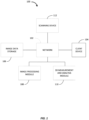
- FIG. 1 is an example of a computer environment 100 suitable for implementing certain embodiments described herein.
- the computer environment 100 may include a network 102.
- the network 102 may take various forms.
- the network 102 may be a local area network installed at a surgical site.
- the network 102 may be a wide area network such as the Internet, for e in other embodiments, the network 102 may be a combination of local area networks and wide area networks.
- the network will allow for secured communications and data to be shared between various computing devices.
- a client device 104 is a client device 104.
- the client device 104 may be a typical personal computer device that runs an off-the-shelf operating systems such as Windows, Mac OS, Linux, Chrome, or some other operating system.
- the client device 104 may have application software installed to allow it to interact via the network 102 with other software stored on various other modules and devices in the computing environment 100.
- This application software may take the form of a web browser capable of accessing a remote application service.
- the application software may be a client application installed in the operating system of the client device 104.
- Client device 104 may also take the form of a specialized computer, specifically designed medical imaging work, or even more specifically for mitral valve quantification.
- the client device 104 may further take the form of a mobile device or tablet computer configured to communicate via the network 102 and further configured to run one or more software modules to allow a user to perform various methods described herein.
- the computer environment 100 may further include image data storage 106.
- the image data storage 106 takes the form of a large database designed to store image files captured by a scanning device 112. These images may be DICOM images, or other types of images.
- the image data storage 106 may be part of a scanning device 112, or alternatively it may be part of a client computing device 104.
- the image data storage 106 may also be in a standalone database having dedicated storage optimized for medical image data.
- the computer environment 100 may also include a scanning device 112.
- the scanning device 112 may typically is a medical imaging device which scans a patient to create images of their anatomy. In the computing environment 100 shown in Figure 1 , the scanning device 112 may be a CT scanner or an MRI device. However, a skilled artisan will appreciate that other scanning technologies may be implemented which provide imaging data that can be used to create three-dimensional anatomical models.
- the scanning device 112 may be configured to create cross-sectional images of a patient's heart. Those images may be stored in the image data storage 106, and utilized to create three-dimensional models of the heart.
- the computing environment 100 may also include an image processing module 108.
- the image processing module 108 may take the form of computer software, hardware, or a combination of both which retrieves the medical imaging data from image data storage 106 and generates a three-dimensional surface model using stacks of 2-D image data.
- the image processing module 108 may be a commercially available image processing software for three-dimensional design and modeling such as the Mimics application from Materialise NV. However, other image processing software may be used.
- the image processing module 108 may be provided via a web-based network application that is accessed by a computer over the network (such as client device 104, for example).
- the image processing module may be a software application that is installed directly on the client device 104, and accesses image data storage 106 via the network 102.
- the image processing module 108 may be any combination of software and/or hardware located within the computing environment 100 which provides image processing capabilities on the image data stored within the image data storage 106.
- the computing environment also may include a three-dimensional measurement and analysis module 110 ("3-D measurement and analysis module").
- the 3-D measurement and analysis module 110 may be software that is complementary to and/or bundled with the image processing module 108.
- the 3-D measurement and analysis module 110 may be a bundled projects such as 3matic ® from Materialise NV.
- the 3-D measurement and analysis module may also take the form of general CAD and design software such as, for example, AutoCAD or SolidWorks.
- the 3-D measurement and analysis module may be a specialized application created specifically for mitral valve quantification purposes.
- the 3-D measurement and analysis module 110 will be generally used to determine precise measurements of various aspects of the patient anatomy in order to determine the appropriate dimensions for a surgical implant.
- the heart anatomy is measured and in order to determine appropriate dimensions for a transcatheter mitral valve implant.
- the 3-D measurement and analysis module 110 may be a network-based application which is accessed via a web browser by one or more client devices 104. It may also be a native application installed into the operating system of a computer such as, client device 104 for example. In still other embodiments, the 3-D measurement and analysis module 110 may be a network application which is run as a client/server implementation.
- the computer system 200 may generally take the form of computer hardware configured to execute certain processes and instructions in accordance with various aspects of one or more embodiments described herein.
- the computer hardware may be a single computer or it may be multiple computers configured to work together.
- the computing device 200 includes a processor 202.
- the processor 202 may be one or more standard personal computer processor such as those designed and/or distributed by Intel, Advanced Micro Devices, Apple, ARM, or Motorola.
- the processor 202 may also be a more specialized processor designed specifically for image processing and/or analysis.
- the computing device 200 may also include a display 204.
- the display 204 may be a standard computer monitor such as, an LCD monitor as is well known.
- the display 204 may also take the form of a display integrated into the body of the computing device, for example as with an all-in-one computing device or a tablet computer.
- the computing device 200 may also include input/output devices 206. These may include standard peripherals such as keyboards, mice, printers, and other basic I/O software and hardware.
- the computing device 200 may further include memory 208.
- the memory 208 may take various forms.
- the memory 208 may include volatile memory 210.
- the volatile memory 210 may be some form of random-access memory, and may be generally configured to load executable software modules into memory so that the software modules may be executed by the processor 202 in a manner well known in the art.
- There the software modules may be stored in a nonvolatile memory 212.
- the non-volatile memory 212 may take the form of a hard disk drive, a flash memory, a solid-state hard drive or some other form of non-volatile memory.
- the non-volatile memory 104B may also be used to store non-executable data, such database files and the like.
- the computer device 200 also may include a network interface 214.
- the network interface may take the form of a network interface card and its corresponding software drivers and/or firmware configured to provide the system 200 with access to a network (such as the Internet, for example).
- the network interface card 214 may be configured to access various different types of networks, such as those described above in connection with Figure 1 .
- the network interface card 214 may be configured to access private networks that are not publicly accessible.
- the network interface card 214 may also be configured to access wireless networks such using wireless data transfer technologies such as EVDO, WiMax, or LTE network.
- a single network interface 214 is shown in Figure 2 , multiple network interface cards 214 may be present in order to access different types of networks.
- a single network interface card 214 may be configured to allow access to multiple different types of networks.
- the computing environment 100 shown in Figure 1 may generally include one, a few, or many different types of computing devices 200 which work together to carry out various embodiments described below.
- computing devices 200 which work together to carry out various embodiments described below.
- a skilled artisan will readily appreciate that various different types of computing devices and network configurations may be implemented to carry out the inventive systems and methods disclosed herein.
- FIG. 3 is a high-level flow diagram showing a process by which quantification of space and/or volume of a particular area of a patient's anatomy, in this example the mitral valve, may be realized according to one or more embodiments.
- Process begins at block 302, wherein image of the patient's heart acquired.
- the image may be acquired using the scanning device 112 shown in Figure 1 , such as a CT scanner or an MRI machine.
- a contrast agent may be used in order to improve the visibility of various internal structures of the heart.
- the image (or images) acquired using the scanning device 112 may be stored in image data storage 106 or some other computer memory accessible via the computer network 102.
- the process then moves to block 304.
- There a 3-D model of blood volume is calculated based on the acquired image.
- the use of a contrast agent in the previous step allows for the 3-D modeling of the blood volume.
- the 3-D model may be calculated using the image processing module 108, or some other software and/or hardware designed to generate 3-D models from
- the anatomical structures of the heart may be reconstructed at block 306.
- This reconstruction may also be performed using the image processing module 108.
- the reconstruction of the heart anatomy typically begins with segmentation of the left side of the heart, followed by optimization of the segmented and reconstructed 3-D model using optimization tools such as wrapping functions and smoothing functions to clean the surfaces of the models.
- the anatomy of the mitral valve apparatus is characterized by defining control points and taking measurements of relevant anatomical structures. Typically, these measurements are performed using the 3-D measurement and analysis module 110. As discussed above, this 3-D measurement and analysis module 110 may be software that is bundled or even integrated with the image processing module 108. These measurements may include various steps. For example, using the 3-D measurement and analysis module 110, control points may be placed on the 3-D model of the heart which define the mitral valve annulus. These control points may be defined using a spline drawing function provided by the 3-D measurement and analysis module 110.
- the measurements may further include calculation of the 3-D surface area of the mitral valve annulus based on the spline. Additional measurements and analysis may be performed relating to the mitral valve annulus. For example, and as will be discussed below, one or more planes can be fit through the mitral valve annulus using the 3-D measurement and analysis module. Using these defined planes, additional measurements can be taken which help to more precisely define the actual geometry of the mitral valve annulus.
- anatomical structure may be vulnerable because a transcatheter mitral valve implant will not typically be fixed within the mitral valve. Rather, the mitral valve apparatus will experience a high degree of mobility. This movement can potentially damage surrounding anatomical structures from either collisions or protrusions from the device.
- This assessment may be made based on the measurements taken in the previous step. Moreover, it may further be a visual assessment.
- based on the measurements taken and the assessed vulnerabilities, and appropriately sized mitral valve device may then be selected.
- the mitral valve quantification process may include characterizing the anatomy of the mitral valve apparatus.
- Figure 4 is a flow diagram providing one example of a sub process which may be implemented to characterize the anatomy is provided in block 308. The sub process begins at block 401 where, using the image processing module, the mitral valve annulus is defined within the reconstructed heart model. Additional details about how the mitral valve annulus is defined will be discussed in connection with Figure 5 below.
- the process moves to block 403. There, the 3-D surface area of the mitral valve annulus is calculated.
- the process next moves to block 405 where a plane is fitted through the mitral valve annulus.
- the plane may be generated by using a create datum plane function provided by the image processing module 108 and/or the 3-D measurement and analysis module 110.
- the 3-D surface area of the mitral valve annulus (the mitral surface) may be used as the fitting entity.
- the process moves to block 407.
- the visualization of the 3-D heart model is enhanced by adding additional anatomical detail to the model and generating a view of a hollowed heart anatomy. Additional details about this enhancement of the visualization are provided below in connection with Figure 6 .
- the process then moves to block 409.
- distance measurements are performed on the model in order to determine various dimensional attributes that may impact the size of the transcatheter mitral valve implant. These distance measurements may be performed against various aspects of the 3-D model, and are discussed in further detail below in connection with Figure 8 .
- FIG. 5 is a flow diagram which provides additional details about the process of defining the mitral valve annulus in the 3-D model.
- the mitral valve annulus may be defined by first placing control points on a user interface which graphically displays the 3-D model of the heart to the user.
- the control points may be placed using a spline drawing function provided by the 3-D measurement and analysis module 110.
- the initial control point may then be selected to close the spline at block 504.
- the process may then move to block 506 where the control points may be verified and edited based on reformatted image views generated from the data initially required by the scanning device 112.
- control points selected by the user may be superimposed on each of a coronal reformation, a sagittal reformation, as well as a conventional axial view. If the control points are inconsistent with the anatomy shown in any of the reformatted image views, they may be edited to ensure that they are consistent with the originally acquired image data. If the control points are consistent with the anatomy shown in the reformatted image views, then the process then may move to block 508 where the spline object is saved and exported for use in the 3-D heart model.
- Figure 6 provides an example of one implementation of the visual enhancement process according to one embodiment.
- the process begins at block 601, where a wall thickness is added to the 3-D heart model. Because the original 3-D heart model was generated using images based on blood volume, those images do not account for wall thickness in the model.
- the wall thickness may be added by applying a hollow operation to the heart model and specifying a wall thickness as part of that operation.
- the process may then move to block 603 where a plane intersecting the heart may be defined.
- the plane may be used to section the anatomy to provide an internal view of the geometry of the left heart side.
- a three-point method may be implemented to define the plane which intersects the septum and the ascending aorta.
- a cut function may then be applied to the hollowed heart anatomy at block 605.
- the defined plane on the septum may be used as the cutting entity. Applying the cut function results in a cutaway view of the interior of the heart anatomy.
- FIG 7 is a more detailed flowchart of the distance measurement step shown in block 409 of Figure 4 .
- various distance measurements may be taken using the 3-D measurement and analysis module 110.
- the process begins at block 702 where the distance between papillary muscle heads is determined.
- a user may identify and select two points in the cutaway view generated by the cut function applied in Figure 6 . These two selected points may correspond to each of the papillary muscle heads.
- the 3-D measurement and analysis module 110 may, based on the location of these two points, determine the distance between the papillary muscle heads.
- the process moves to block 704.
- the distance from each of the papillary muscle heads to the mitral plane is calculated. In this particular example the distance is calculated normal to the mitral plane, and not at the geometric center of the plane. Additional measurements may also be performed.
- the process next they move to block 706 where the distance from the papillary muscle heads to the geometric center of the mitral valve annulus is calculated.
- the process moves to block 708 where the distance from the apex of the heart to the geometric center of the mitral valve annulus is determined.
- the process then moves to block 710, where the distance from the left atrium roof to the geometric center of the mitral valve annulus is calculated.
- a transcatheter mitral valve implant may include various metallic components. When implanted into the mitral valve annulus, it takes a specific height and shape. The height and shape of the implanted device may interact substantially with several anatomical structures within the patient. For example, on the atrial side, the implant could collide with touch and possibly damage the thin walls of the atrium. In particular, the contours of the implant could potentially puncture the atrial wall because of its high mobility and deformation between systole vs diastole.
- the deformations are also quite large, and the papillary muscles can interfere with the valves on the device by pushing against the frame of the valve. Additionally, they may even interfere with the new leaflets which are sewn into the metallic structure. This would mean the new valve would not be able to close or might even wear out faster because of this mechanical and repeatable contact. Accordingly, the distance measurements may be analyzed to account for the mobility of the device and select a size which will avoid these problems.
- FIG. 8A a more detailed flowchart is provided which provides an example of a detailed process for assessing vulnerable anatomical structures shown in Figure 3 .
- This sub-process begins at block 801.
- a user may slice the anatomy both above and below the mitral valve plane.
- the translate function may be used to copy the mitral valve plane above and below the mitral valve annulus.
- the plane may be translated at 5 mm increments up to 20 mm.
- an intersection curve may be calculated between the blood volume anatomy provided by a 3-D model and each plane in order to capture the contour of the lumen through each slice.
- the average diameter measurements may be extracted using an arc method or some other function that can be used to create an arc or curve.
- Figure 8B is an example of a process by which the best size fit can be selected according to one or more embodiments.
- the process begins at block 811, where a primitive cylinder may be generated to simulate the implant.
- the primitive cylinder may be generated based indirectly on the measurements determined in connection with Figure 7 , and also more directly based on the captured contour of the lumen of the mitral valve annulus obtained using the process described in connection with Figure 8A above.
- the process then moves to block 813 where the primitive cylinder implant is verified by visualizing the contours of the objects overlaid on the original scanned images.
- the primitive generated in this example is a cylinder, a skilled artisan will readily appreciate that any number of other primitives may also be used separately or in combination with the cylinder.
- Figures 9-14 provide examples of graphical user interfaces and computer generated images which may be utilized in performing the process described above.
- FIG 9 an example of a graphical user interface environment which may be used to define the mitral valve annulus as described above in connection Figure 5 .
- a 3-D surface model of the left side of the patient's heart is provided.
- superimposed onto the 3-D surface model of the heart 900 is a spline 906 created using a spline drawing function provided by the image processing module 108.
- the spline 406 defines the mitral valve annulus and is created by the user inputting the control points shown enclosing the spline by selecting the initial control point.
- Figures 10-12 is an example of graphical user interface environment which can be used to calculate the 3-D surface area of the mitral valve annulus and fit a plane through the annulus as described above in blocks 403 and 405 of Figure 4 .
- Figure 10 illustrates how the 3-D surface area of the mitral valve annulus is displayed. As shown the surface area 1002 of the mitral valve annulus is referenced and various properties 1004, including the calculated surface area 1006 are shown. The calculated surface area 1006 may be used to calculate the size of the implant device. In addition to the calculated surface area, the annulus projected circumference or a combination of other measurements may also govern the ultimate best fitting device.
- Figures 11A and 11B provide graphical depictions of aspects of a user interface by which a plane may be fit through the mitral annulus using a create datum plane function.
- a create datum plane operation 1102 has been selected.
- a fit plane method 1104 for creating the datum plane has been selected, and the fitting entity 1106 has been chosen.
- the mitral surface from Figure 10 has been selected as the fitting entity.
- Figure 11B provides a graphical illustration of how the plane is fit onto the 3-D heart model. As shown, a plane has been fit through the mitral annulus, with the geometric center 1108 of the mitral valve annulus as the origin of the fit plane 1110.
- wall thickness may be added to the 3-D heart model, and a plane may be defined intersecting the heart which can then be cut to reveal a hollowed heart anatomy.
- Figure 12 a graphical illustration is provided showing how the intersecting plane may be defined.
- the intersecting plane 1203 is defined using a three-point method which intersects the inter-ventricular septum 1205 (separating the left ventricle from the right ventricle) and ascending aorta 1207.
- Figure 13 provides a cutaway view 1302 of the 3-D heart model after the cut function has been applied to the hollowed heart anatomy as described at block 605 of Figure 6 .
- the defined plane shown in Figure 12 has been used as the cutting entity.
- Figure 14 provides a visual illustration of how the various measurements described in Figure 7 may be carried out within a graphical user interface environment.
- Figure 14 shows the cutaway view 1302 from Figure 13 .
- the cutaway view 1302 shows various measurements that have been extracted using a point-to-point measurement tool.
- Various measurements are shown with respect to the geometric center 1403 of the mitral annulus.
- Other measurements include the distance between the papillary muscle heads (37.42 mm), distance from the papillary muscle heads to the mitral plane (18.02 mm and 13.99 mm), the distance from the papillary muscle heads to the geometric center of the mitral valve annulus (26.12 mm and 23.16 mm), and the distance from the apex of the left ventricle to the geometric center of the mitral valve annulus (110.21 mm).
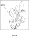
- FIGs 15 and 16 a visual illustration of the process described in Figure 8A is provided.
- a Translate function three measurement and analysis module 110 has been used to copy the mitral valve plane 1504 above and below the annulus.
- the plane is translated at 5 mm increments to 20 mm as reflected by the values in the distance field 1506 and the number of copies field 1508.
- an intersection curve may be calculated between the blood volume anatomy 302 and each plane 1504, thereby capturing the contour of the lumen through each slice.
- Figure 16 a graphical illustration is shown depicting how the average diameter measurement is extracted for each cross-section. As discussed above, these measurements may be extracted at these cross sections using an arc method.
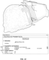
- Figure 17 provides a visual illustration of one graphical user interface environment that may be used to simulate an implant using a primitive cylinder as described in connection with Figure 8B above.
- the mitral annulus curve 1702 is projected into the plane 1704 fit through the mitral annulus.
- the mitral annulus curve has been exported resulting in a flattened annulus 1706 and the diameter of the flattened annulus may be measured and used to size the primitive implant.
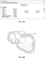
- Figures 18A and 18B provide examples of a graphical user interface which may be used to create a simulated implant using a primitive cylinder. As shown in Figure 18A , the create cylinder operation in the 3-D measurement and analysis module 110 is applied using the measurements obtained above. Figure 18B shows the generated cylinder 1801 positioned within the mitral valve annulus.
- the cylinder or some other type of geometry may be "virtually" implanted as shown in Figure 19A .
- a distance mapping may be performed with respect to the anatomy. This distance mapping may quantify the space that is available between the implanted device and each relevant item of anatomy.
- a primitive 1902 (which in this example is a cylinder, but may take various other forms) has been virtually placed within the mitral valve annulus.
- a distance mapping is used to identify anatomical the position of anatomical structures in the heart (such as the walls of the atrium) or other anatomical features 1908 as shown in Figure 19C .
- the distance mapping provides a clear visualization of the spacing between the proposed implant and the anatomy.
- the valve may be a pulmonary branch valve.
- the systems and methods described above may be used in the treatment of pulmonary artery stenosis.
- measurement and quantification of holes resulting from congenital heart defects may also be performed to select an appropriate size for a catheter implant or other device for implantation.
- ASDs atrial septal defects
- VSDs ventricular septal defects
Abstract
acquiring scanned images of the organ;
generating, by a computer, a 3-D model of the organ based on the scanned images;
placing control points in the 3-D model of the organ to define a 3-D valve annulus of the valve of the organ;
taking one or more measurements of relevant anatomical structures based on the 3-D valve annulus; and
selecting the size for the device to be implanted based on the measurements, wherein selecting the size of the device to be implanted comprises:
generating a primitive shape to simulate the device based on the measurements;
virtually placing the primitive shape within the 3-D model of the organ; and
verifying the primitive shape by visualizing, by the computer, the primitive shape overlaid on a visualization of the organ.
Description
- This application relates to quantification of space and volume of areas in a patient's anatomy. In some aspects, this application relates specifically to mitral valve quantification. Even more specifically, this application relates to a system and method for quantifying the mitral valve apparatus and its surroundings for use in selecting an appropriately sized valve in a catheter-based transcatheter mitral valve repair procedure.
- The human heart is a complex organ having many working parts which are critical to the proper functioning of the heart and the blood circulation and provides throughout the human body. The human heart is generally made up of four hollow chambers, the right atrium, the right ventricle, the left atrium, and the left ventricle. One of the keys to a properly functioning heart is the regulation of blood flow through these chambers. Regulation of blood throw through and between these chambers is provided by valves. For example, between the right atrium and the right ventricle, there is an atrioventricular opening.
- The tricuspid valve is situated at that opening, and permits blood to move from the right atrium into the right ventricle. The valve opens when the blood pressure on the atrium site is greater than that on the ventricular side. When the valve opens, blood is permitted to flow from the right atrium into the right ventricle. When blood pressure is greater on the ventricle side, the valve closes. When the valve closes, blood is prevented from moving back in the other direction.
- In the healthy heart, blood flow is also regulated between the left atrium and left ventricle. Here, the mitral valve allows blood to enter the left ventricle from the left atrium when the left atrium fills with blood and the pressure within the left atrium increases to a level above that of the left ventricle. When open, blood flows in a downward direction from the left atrium into the left ventricle, where it is pushed out to the rest of the body as part of the greater circulatory process. When a healthy mitral valve closes, blood flow between the two chambers is stopped, and this closing prevents a reversal of blood flow.
- Unfortunately, mitral valves do not always function normally. An abnormally functioning mitral valve can lead to severe health problems. One abnormality associated with the mitral valve is mitral regurgitation ("MR"). Mitral regurgitation is a disorder in which the mitral valve does not close properly during contraction of the left ventricle. This causes blood that has passed from the left atrium into the left ventricle to reverse its flow back into the left atrium.
- Mitral regurgitation may be treated surgically. One surgical option includes the replacement of the mitral valve where the mitral valve is replaced with either a bio prosthetic replacement or a synthetic replacement. Another surgical option includes repair of the mitral valve. Although mitral valve repair is generally seen as preferable to mitral valve replacement due to the less invasive nature of the procedure, at present, both options require open-heart surgery. Because many candidates for mitral valve replacement and repair are not good candidates for tolerating the stress of open-heart surgery, there has been ongoing research directed to developing transcatheter mitral valves. These transcatheter mitral valves can be introduced using a catheter-based system, obviating the need for a surgical procedure. Using noninvasive catheter-based implant techniques, the physical trauma associated with an open heart surgery may be minimized and more patients may be treated effectively for the mitral regurgitation disorder.
- Although the use of transcatheter mitral valves shows great promise, there are significant challenges involved with effectively deploying these types of devices. In an open surgical procedure, the surgeon has complete access to the surgical site. Consequently, the surgeon is able to visually survey the site in order to perform the procedure effectively. When using the catheter-based system, however, the surgeon must rely and various imaging technologies to provide guidance to positioning and fit of a repair and/or replacement valve. Because transcatheter mitral valves are inserted using a delivery catheter, it is critical that the transcatheter mitral valve introduced into the patient have an appropriate size and shape to conform to the patient's anatomy. The need for appropriate sizing and shaping of implants extends well beyond mitral valve-related procedures, and may be useful in various different surgical contexts. At present, methodologies for quantifying the pertinent measurements of the mitral valve are inadequate. Accordingly, there is a need for a standardized measurement method which can be used for planning implantation of medical devices, including transcatheter mitral valve implantation.
- In one embodiment, a method of method of mitral valve quantification is provided. The method may include generating a three-dimensional heart model and defining a three-dimensional mitral valve annulus. The method may further include fitting a plane through the three-dimensional mitral valve annulus. The distance between at least two papillary muscle heads may then be measured. The method further may include defining an average diameter of at least one cross section around the micro valve annulus. Based on the average diameter, a size of an implant may be selected.
- In another embodiment, a computer-readable medium having computer-executable instructions stored thereon is provided. When the instructions are executed by a processor of a computing device, they cause the computing device to perform a method of mitral valve quantification. The method may include generating a three-dimensional ("3-D") model of a patient's heart from scanned images of the patient's heart and defining a 3-D mitral valve annulus. The method may also include fitting a plane through the 3-D mitral valve annulus. Distance may be measured between a first papillary muscle head and a second papillary muscle head in the 3-D model, and an average diameter of at least one cross section around the mitral valve annulus may be defined. The method may further include determining a size of an implant to be implanted.
-
-
Figure 1 is a block diagram of one example of a computing environment suitable for practicing various embodiments disclosed herein. -
Figure 2 is a high-level system diagram of a computing system that may be used in accordance with one or more embodiments. -
Figure 3 is a flowchart showing an example of a method of providing mitral valve quantification according to one or more embodiments. -
Figure 4 is a flowchart of a sub process showing a more detailed view of the anatomical characterization of the mitral valve apparatus fromFigure 3 according to one embodiments. -
Figure 5 is a flowchart showing an example of a process by which a mitral valve annulus may be defined as described in the process shown inFigure 4 . -
Figure 6 is a flowchart providing a more detailed view of the visualization enhancement process fromFigure 4 according to one or more embodiments. -
Figure 7 is a flowchart providing additional detail about the distance measurement process described inFigure 4 . -
Figure 8A is a flowchart showing a sub-process for the vulnerable anatomical structure assessment referenced atblock 310 inFigure 3 . -
Figure 8B is a flowchart showing an example of how the best fit size for an implant may be determined in accordance with one or more embodiments. -
Figure 9 is an example of a graphical user interface environment which may be used to define the mitral valve annulus according to the process described inFigure 5 . -
Figures 10-12 provide examples of graphical user interfaces which can be used to calculate the 3-D surface area of the mitral valve annulus and fit a plane through the annulus according to aspects of the process described inFigure 4 . -
Figure 13 is a graphical illustration of open hollowed heart anatomy constructed according to aspects of the process described inFigure 6 . -
Figure 14 is the open hollowed heart anatomy fromFigure 13 with various point-to-point measurements defined therein. -
Figures 15 and16 provide visual illustration of various aspects of the process described in connection withFigure 8A . -
Figures 17-19C provide visual depictions of graphical user interface environments that may be used to simulate an implant using a primitive as described in connection withFigure 8B above. - As noted above, determining the appropriate dimensions for an implanted device can play an important role in the success of an implantation procedure. In the context of the transcatheter mitral valve repair, appropriate dimensions and sizing of the device plays an important role in the success of a transcatheter mitral valve repair procedure. Recognizing the importance of mitral valve quantification, the inventors have devised systems and methods which quantify the mitral valve in three dimensions. The systems and methods typically provide for the calculation of a three-dimensional model of the blood volume in a patient's heart. From the three-dimensional model, a model of the myocardium and main anatomical structures in the heart can be also reconstructed. Using this reconstructed heart, a series of measurements may be performed from which a virtual insertion of a transcatheter mitral valve device can be simulated using three-dimensional computer modeling. Once the device has been virtually implanted within the three-dimensional heart model, the surgical site may be assessed by analyzing the potential impact of the device on anatomical structures could be harmed by physical features of the device. Based on that analysis, an appropriately sized mitral valve device can be selected for use in the repair procedure.
- The systems and methods described herein may be implemented in a computing environment comprising one or more computing devices configured to provide various functionalities.
Figure 1 is an example of acomputer environment 100 suitable for implementing certain embodiments described herein. Thecomputer environment 100 may include anetwork 102. Thenetwork 102 may take various forms. For example, thenetwork 102 may be a local area network installed at a surgical site. In some embodiments, thenetwork 102 may be a wide area network such as the Internet, for e in other embodiments, thenetwork 102 may be a combination of local area networks and wide area networks. Typically, the network will allow for secured communications and data to be shared between various computing devices. Among these computing devices is aclient device 104. Theclient device 104 may be a typical personal computer device that runs an off-the-shelf operating systems such as Windows, Mac OS, Linux, Chrome, or some other operating system. Theclient device 104 may have application software installed to allow it to interact via thenetwork 102 with other software stored on various other modules and devices in thecomputing environment 100. This application software may take the form of a web browser capable of accessing a remote application service. Alternatively, the application software may be a client application installed in the operating system of theclient device 104.Client device 104 may also take the form of a specialized computer, specifically designed medical imaging work, or even more specifically for mitral valve quantification. Theclient device 104 may further take the form of a mobile device or tablet computer configured to communicate via thenetwork 102 and further configured to run one or more software modules to allow a user to perform various methods described herein. - The
computer environment 100 may further includeimage data storage 106. Typically, theimage data storage 106 takes the form of a large database designed to store image files captured by ascanning device 112. These images may be DICOM images, or other types of images. Theimage data storage 106 may be part of ascanning device 112, or alternatively it may be part of aclient computing device 104. Theimage data storage 106 may also be in a standalone database having dedicated storage optimized for medical image data. Thecomputer environment 100 may also include ascanning device 112. Thescanning device 112 may typically is a medical imaging device which scans a patient to create images of their anatomy. In thecomputing environment 100 shown inFigure 1 , thescanning device 112 may be a CT scanner or an MRI device. However, a skilled artisan will appreciate that other scanning technologies may be implemented which provide imaging data that can be used to create three-dimensional anatomical models. - As will be explained in detail below, the
scanning device 112 may be configured to create cross-sectional images of a patient's heart. Those images may be stored in theimage data storage 106, and utilized to create three-dimensional models of the heart. To that end, thecomputing environment 100 may also include animage processing module 108. Theimage processing module 108 may take the form of computer software, hardware, or a combination of both which retrieves the medical imaging data fromimage data storage 106 and generates a three-dimensional surface model using stacks of 2-D image data. Theimage processing module 108 may be a commercially available image processing software for three-dimensional design and modeling such as the Mimics application from Materialise NV. However, other image processing software may be used. In some embodiments, theimage processing module 108 may be provided via a web-based network application that is accessed by a computer over the network (such asclient device 104, for example). Alternatively, the image processing module may be a software application that is installed directly on theclient device 104, and accessesimage data storage 106 via thenetwork 102. In general, theimage processing module 108 may be any combination of software and/or hardware located within thecomputing environment 100 which provides image processing capabilities on the image data stored within theimage data storage 106. - The computing environment also may include a three-dimensional measurement and analysis module 110 ("3-D measurement and analysis module"). The 3-D measurement and
analysis module 110 may be software that is complementary to and/or bundled with theimage processing module 108. For example, the 3-D measurement andanalysis module 110 may be a bundled projects such as 3matic® from Materialise NV. The 3-D measurement and analysis module may also take the form of general CAD and design software such as, for example, AutoCAD or SolidWorks. In some embodiments, the 3-D measurement and analysis module may be a specialized application created specifically for mitral valve quantification purposes. As will be explained in further detail below, the 3-D measurement andanalysis module 110 will be generally used to determine precise measurements of various aspects of the patient anatomy in order to determine the appropriate dimensions for a surgical implant. In particular examples provided below, the heart anatomy is measured and in order to determine appropriate dimensions for a transcatheter mitral valve implant. As with theimage processing module 108, the 3-D measurement andanalysis module 110 may be a network-based application which is accessed via a web browser by one ormore client devices 104. It may also be a native application installed into the operating system of a computer such as,client device 104 for example. In still other embodiments, the 3-D measurement andanalysis module 110 may be a network application which is run as a client/server implementation. - Various embodiments of the invention may be implemented using general and/or special purpose computing devices. Turning now to
Figure 2 , an example of acomputing device 200 suitable for implementing various embodiments of the invention is shown. Thecomputer system 200 may generally take the form of computer hardware configured to execute certain processes and instructions in accordance with various aspects of one or more embodiments described herein. The computer hardware may be a single computer or it may be multiple computers configured to work together. Thecomputing device 200 includes aprocessor 202. Theprocessor 202 may be one or more standard personal computer processor such as those designed and/or distributed by Intel, Advanced Micro Devices, Apple, ARM, or Motorola. Theprocessor 202 may also be a more specialized processor designed specifically for image processing and/or analysis. Thecomputing device 200 may also include adisplay 204. Thedisplay 204 may be a standard computer monitor such as, an LCD monitor as is well known. Thedisplay 204 may also take the form of a display integrated into the body of the computing device, for example as with an all-in-one computing device or a tablet computer. - The
computing device 200 may also include input/output devices 206. These may include standard peripherals such as keyboards, mice, printers, and other basic I/O software and hardware. Thecomputing device 200 may further includememory 208. Thememory 208 may take various forms. For example, thememory 208 may includevolatile memory 210. Thevolatile memory 210 may be some form of random-access memory, and may be generally configured to load executable software modules into memory so that the software modules may be executed by theprocessor 202 in a manner well known in the art. There the software modules may be stored in anonvolatile memory 212. Thenon-volatile memory 212 may take the form of a hard disk drive, a flash memory, a solid-state hard drive or some other form of non-volatile memory. The non-volatile memory 104B may also be used to store non-executable data, such database files and the like. - The
computer device 200 also may include anetwork interface 214. The network interface may take the form of a network interface card and its corresponding software drivers and/or firmware configured to provide thesystem 200 with access to a network (such as the Internet, for example). Thenetwork interface card 214 may be configured to access various different types of networks, such as those described above in connection withFigure 1 . For example thenetwork interface card 214 may be configured to access private networks that are not publicly accessible. Thenetwork interface card 214 may also be configured to access wireless networks such using wireless data transfer technologies such as EVDO, WiMax, or LTE network. Although asingle network interface 214 is shown inFigure 2 , multiplenetwork interface cards 214 may be present in order to access different types of networks. In addition, a singlenetwork interface card 214 may be configured to allow access to multiple different types of networks. - In general, the
computing environment 100 shown inFigure 1 may generally include one, a few, or many different types ofcomputing devices 200 which work together to carry out various embodiments described below. A skilled artisan will readily appreciate that various different types of computing devices and network configurations may be implemented to carry out the inventive systems and methods disclosed herein. -
Figure 3 is a high-level flow diagram showing a process by which quantification of space and/or volume of a particular area of a patient's anatomy, in this example the mitral valve, may be realized according to one or more embodiments. Process begins atblock 302, wherein image of the patient's heart acquired. The image may be acquired using thescanning device 112 shown inFigure 1 , such as a CT scanner or an MRI machine. In acquiring the image, a contrast agent may be used in order to improve the visibility of various internal structures of the heart. The image (or images) acquired using thescanning device 112 may be stored inimage data storage 106 or some other computer memory accessible via thecomputer network 102. The process then moves to block 304. There a 3-D model of blood volume is calculated based on the acquired image. The use of a contrast agent in the previous step allows for the 3-D modeling of the blood volume. The 3-D model may be calculated using theimage processing module 108, or some other software and/or hardware designed to generate 3-D models from CT and/or MRI image data. - Using the 3-D model of the blood volume, the anatomical structures of the heart may be reconstructed at
block 306. Typically, it is easier to first obtain the blood volume from the clearly visible contrast agent and then use that to create the myocardium. However, a skilled artisan will appreciate that it is also possible to directly create the myocardial model. This reconstruction may also be performed using theimage processing module 108. The reconstruction of the heart anatomy typically begins with segmentation of the left side of the heart, followed by optimization of the segmented and reconstructed 3-D model using optimization tools such as wrapping functions and smoothing functions to clean the surfaces of the models. - The process next moves to block 308. There, the anatomy of the mitral valve apparatus is characterized by defining control points and taking measurements of relevant anatomical structures. Typically, these measurements are performed using the 3-D measurement and
analysis module 110. As discussed above, this 3-D measurement andanalysis module 110 may be software that is bundled or even integrated with theimage processing module 108. These measurements may include various steps. For example, using the 3-D measurement andanalysis module 110, control points may be placed on the 3-D model of the heart which define the mitral valve annulus. These control points may be defined using a spline drawing function provided by the 3-D measurement andanalysis module 110. - With the mitral valve annulus defined, the measurements may further include calculation of the 3-D surface area of the mitral valve annulus based on the spline. Additional measurements and analysis may be performed relating to the mitral valve annulus. For example, and as will be discussed below, one or more planes can be fit through the mitral valve annulus using the 3-D measurement and analysis module. Using these defined planes, additional measurements can be taken which help to more precisely define the actual geometry of the mitral valve annulus.
- Once the measurements have been taken, the process then moves to block 310. There an assessment is made of vulnerable anatomical structures. An anatomical structure may be vulnerable because a transcatheter mitral valve implant will not typically be fixed within the mitral valve. Rather, the mitral valve apparatus will experience a high degree of mobility. This movement can potentially damage surrounding anatomical structures from either collisions or protrusions from the device. This assessment may be made based on the measurements taken in the previous step. Moreover, it may further be a visual assessment. Finally, at
block 312, based on the measurements taken and the assessed vulnerabilities, and appropriately sized mitral valve device may then be selected. - As discussed above in connection with
block 308 ofFigure 3 , in certain embodiments, the mitral valve quantification process may include characterizing the anatomy of the mitral valve apparatus.Figure 4 is a flow diagram providing one example of a sub process which may be implemented to characterize the anatomy is provided inblock 308. The sub process begins atblock 401 where, using the image processing module, the mitral valve annulus is defined within the reconstructed heart model. Additional details about how the mitral valve annulus is defined will be discussed in connection withFigure 5 below. Once the mitral valve annulus has been defined, the process moves to block 403. There, the 3-D surface area of the mitral valve annulus is calculated. The process next moves to block 405 where a plane is fitted through the mitral valve annulus. In some embodiments, the plane may be generated by using a create datum plane function provided by theimage processing module 108 and/or the 3-D measurement andanalysis module 110. In fitting the plane through the mitral valve annulus, the 3-D surface area of the mitral valve annulus (the mitral surface) may be used as the fitting entity. - Next, the process moves to block 407. Here, the visualization of the 3-D heart model is enhanced by adding additional anatomical detail to the model and generating a view of a hollowed heart anatomy. Additional details about this enhancement of the visualization are provided below in connection with
Figure 6 . Once the visualization of the 3-D model has been enhanced, the process then moves to block 409. Atblock 409, distance measurements are performed on the model in order to determine various dimensional attributes that may impact the size of the transcatheter mitral valve implant. These distance measurements may be performed against various aspects of the 3-D model, and are discussed in further detail below in connection withFigure 8 . - As indicated above,
Figure 5 is a flow diagram which provides additional details about the process of defining the mitral valve annulus in the 3-D model. In this particular example, the mitral valve annulus may be defined by first placing control points on a user interface which graphically displays the 3-D model of the heart to the user. The control points may be placed using a spline drawing function provided by the 3-D measurement andanalysis module 110. Once each of the control points for the defined mitral valve annulus has been selected, the initial control point may then be selected to close the spline atblock 504. Once the spline has been closed, the process may then move to block 506 where the control points may be verified and edited based on reformatted image views generated from the data initially required by thescanning device 112. For example, the control points selected by the user may be superimposed on each of a coronal reformation, a sagittal reformation, as well as a conventional axial view. If the control points are inconsistent with the anatomy shown in any of the reformatted image views, they may be edited to ensure that they are consistent with the originally acquired image data. If the control points are consistent with the anatomy shown in the reformatted image views, then the process then may move to block 508 where the spline object is saved and exported for use in the 3-D heart model. - Turning now to
Figure 6 , a more detailed flow diagram provides additional details about the visualization enhancement ofblock 407 andFigure 4 . In particular,Figure 6 provides an example of one implementation of the visual enhancement process according to one embodiment. The process begins atblock 601, where a wall thickness is added to the 3-D heart model. Because the original 3-D heart model was generated using images based on blood volume, those images do not account for wall thickness in the model. In some embodiments, the wall thickness may be added by applying a hollow operation to the heart model and specifying a wall thickness as part of that operation. Once the wall thickness has been added, the process may then move to block 603 where a plane intersecting the heart may be defined. In some embodiments, the plane may be used to section the anatomy to provide an internal view of the geometry of the left heart side. In one embodiment, a three-point method may be implemented to define the plane which intersects the septum and the ascending aorta. However, a skilled artisan will appreciate that the precise location of the points can be modified, and that a skilled artisan, will appreciate however, that other methods of obtaining a view of the internal geometry may be utilized. Once the plane intersecting the heart has been defined, a cut function may then be applied to the hollowed heart anatomy atblock 605. In applying the cut function to the hollowed heart anatomy, the defined plane on the septum may be used as the cutting entity. Applying the cut function results in a cutaway view of the interior of the heart anatomy. -
Figure 7 is a more detailed flowchart of the distance measurement step shown inblock 409 ofFigure 4 . In this example, various distance measurements may be taken using the 3-D measurement andanalysis module 110. In this particular example, the process begins atblock 702 where the distance between papillary muscle heads is determined. Utilizing the 3-D measurement andanalysis module 110, a user may identify and select two points in the cutaway view generated by the cut function applied inFigure 6 . These two selected points may correspond to each of the papillary muscle heads. The 3-D measurement andanalysis module 110 may, based on the location of these two points, determine the distance between the papillary muscle heads. - Next, the process moves to block 704. There the distance from each of the papillary muscle heads to the mitral plane is calculated. In this particular example the distance is calculated normal to the mitral plane, and not at the geometric center of the plane. Additional measurements may also be performed. The process next they move to block 706 where the distance from the papillary muscle heads to the geometric center of the mitral valve annulus is calculated. Next the process moves to block 708 where the distance from the apex of the heart to the geometric center of the mitral valve annulus is determined. The process then moves to block 710, where the distance from the left atrium roof to the geometric center of the mitral valve annulus is calculated.
- These distance measurements can be used to select an implant design which avoids collisions with various anatomical structures after implantation. A transcatheter mitral valve implant may include various metallic components. When implanted into the mitral valve annulus, it takes a specific height and shape. The height and shape of the implanted device may interact substantially with several anatomical structures within the patient. For example, on the atrial side, the implant could collide with touch and possibly damage the thin walls of the atrium. In particular, the contours of the implant could potentially puncture the atrial wall because of its high mobility and deformation between systole vs diastole. In addition, on the ventricular side the deformations are also quite large, and the papillary muscles can interfere with the valves on the device by pushing against the frame of the valve. Additionally, they may even interfere with the new leaflets which are sewn into the metallic structure. This would mean the new valve would not be able to close or might even wear out faster because of this mechanical and repeatable contact. Accordingly, the distance measurements may be analyzed to account for the mobility of the device and select a size which will avoid these problems.
- Turning now to
Figure 8A , a more detailed flowchart is provided which provides an example of a detailed process for assessing vulnerable anatomical structures shown inFigure 3 . This sub-process begins atblock 801. There using the 3-D measurement andanalysis module 110, a user may slice the anatomy both above and below the mitral valve plane. In some embodiments, the translate function may be used to copy the mitral valve plane above and below the mitral valve annulus. In one specific implementation the plane may be translated at 5 mm increments up to 20 mm. - The process that moves to block 803 where the contour of the lumen (e.g., the mitral valve) is captured through each slice created using the translate function. In some embodiments, an intersection curve may be calculated between the blood volume anatomy provided by a 3-D model and each plane in order to capture the contour of the lumen through each slice. The process next moves to block 805, where the system may extract the average diameter measurements at each of the cross sections. In one embodiment, the average diameter measurements may be extracted using an arc method or some other function that can be used to create an arc or curve.
- As discussed above in connection with
Figure 3 , after vulnerable anatomical structures have been assessed, the size fit for a transcatheter mitral valve implant is determined.Figure 8B is an example of a process by which the best size fit can be selected according to one or more embodiments. The process begins atblock 811, where a primitive cylinder may be generated to simulate the implant. The primitive cylinder may be generated based indirectly on the measurements determined in connection withFigure 7 , and also more directly based on the captured contour of the lumen of the mitral valve annulus obtained using the process described in connection withFigure 8A above. Once the primitive cylinder has been created, the process then moves to block 813 where the primitive cylinder implant is verified by visualizing the contours of the objects overlaid on the original scanned images. Although the primitive generated in this example is a cylinder, a skilled artisan will readily appreciate that any number of other primitives may also be used separately or in combination with the cylinder. - Although the general process described in connection with
Figure 3 and the subprocesses described in connection withFigures 4-8B may be performed using various different configurations of computer hardware and/or software,Figures 9-14 provide examples of graphical user interfaces and computer generated images which may be utilized in performing the process described above. - Turning now to
Figure 9 , an example of a graphical user interface environment which may be used to define the mitral valve annulus as described above in connectionFigure 5 . As shown, a 3-D surface model of the left side of the patient's heart is provided. Superimposed onto the 3-D surface model of theheart 900 is aspline 906 created using a spline drawing function provided by theimage processing module 108. The spline 406 defines the mitral valve annulus and is created by the user inputting the control points shown enclosing the spline by selecting the initial control point. -
Figures 10-12 is an example of graphical user interface environment which can be used to calculate the 3-D surface area of the mitral valve annulus and fit a plane through the annulus as described above inblocks Figure 4 .Figure 10 illustrates how the 3-D surface area of the mitral valve annulus is displayed. As shown thesurface area 1002 of the mitral valve annulus is referenced andvarious properties 1004, including the calculatedsurface area 1006 are shown. Thecalculated surface area 1006 may be used to calculate the size of the implant device. In addition to the calculated surface area, the annulus projected circumference or a combination of other measurements may also govern the ultimate best fitting device. -
Figures 11A and 11B provide graphical depictions of aspects of a user interface by which a plane may be fit through the mitral annulus using a create datum plane function. As shown, a createdatum plane operation 1102 has been selected. Afit plane method 1104 for creating the datum plane has been selected, and thefitting entity 1106 has been chosen. In this particular case, the mitral surface fromFigure 10 has been selected as the fitting entity.Figure 11B provides a graphical illustration of how the plane is fit onto the 3-D heart model. As shown, a plane has been fit through the mitral annulus, with thegeometric center 1108 of the mitral valve annulus as the origin of thefit plane 1110. - As discussed above in connection with
Figure 6 , wall thickness may be added to the 3-D heart model, and a plane may be defined intersecting the heart which can then be cut to reveal a hollowed heart anatomy. Turning now toFigure 12 , a graphical illustration is provided showing how the intersecting plane may be defined. Here, theintersecting plane 1203 is defined using a three-point method which intersects the inter-ventricular septum 1205 (separating the left ventricle from the right ventricle) and ascendingaorta 1207. -
Figure 13 provides acutaway view 1302 of the 3-D heart model after the cut function has been applied to the hollowed heart anatomy as described atblock 605 ofFigure 6 . As discussed in connection withFigure 6 , in this particular example the defined plane shown inFigure 12 has been used as the cutting entity. -
Figure 14 provides a visual illustration of how the various measurements described inFigure 7 may be carried out within a graphical user interface environment.Figure 14 shows thecutaway view 1302 fromFigure 13 . Thecutaway view 1302 shows various measurements that have been extracted using a point-to-point measurement tool. Various measurements are shown with respect to the geometric center 1403 of the mitral annulus. Other measurements include the distance between the papillary muscle heads (37.42 mm), distance from the papillary muscle heads to the mitral plane (18.02 mm and 13.99 mm), the distance from the papillary muscle heads to the geometric center of the mitral valve annulus (26.12 mm and 23.16 mm), and the distance from the apex of the left ventricle to the geometric center of the mitral valve annulus (110.21 mm). - Turning now to
Figures 15 and16 , a visual illustration of the process described inFigure 8A is provided. As shown, a Translate function three measurement andanalysis module 110 has been used to copy themitral valve plane 1504 above and below the annulus. The plane is translated at 5 mm increments to 20 mm as reflected by the values in thedistance field 1506 and the number ofcopies field 1508. As noted above inFigure 8A , an intersection curve may be calculated between theblood volume anatomy 302 and eachplane 1504, thereby capturing the contour of the lumen through each slice. Turning now toFigure 16 , a graphical illustration is shown depicting how the average diameter measurement is extracted for each cross-section. As discussed above, these measurements may be extracted at these cross sections using an arc method. -
Figure 17 provides a visual illustration of one graphical user interface environment that may be used to simulate an implant using a primitive cylinder as described in connection withFigure 8B above. As shown, themitral annulus curve 1702 is projected into theplane 1704 fit through the mitral annulus. The mitral annulus curve has been exported resulting in a flattenedannulus 1706 and the diameter of the flattened annulus may be measured and used to size the primitive implant. -
Figures 18A and 18B provide examples of a graphical user interface which may be used to create a simulated implant using a primitive cylinder. As shown inFigure 18A , the create cylinder operation in the 3-D measurement andanalysis module 110 is applied using the measurements obtained above.Figure 18B shows the generatedcylinder 1801 positioned within the mitral valve annulus. - In some embodiments, the cylinder or some other type of geometry (e.g., primitive shape, CAD or scan file of the device as above) may be "virtually" implanted as shown in
Figure 19A . Here, a distance mapping may be performed with respect to the anatomy. This distance mapping may quantify the space that is available between the implanted device and each relevant item of anatomy. As shown a primitive 1902 (which in this example is a cylinder, but may take various other forms) has been virtually placed within the mitral valve annulus. Turning toFigure 19B , a distance mapping is used to identify anatomical the position of anatomical structures in the heart (such as the walls of the atrium) or otheranatomical features 1908 as shown inFigure 19C . The distance mapping provides a clear visualization of the spacing between the proposed implant and the anatomy. - Using the systems and methods described above, a standardized method provides physicians and researchers the ability to quantify the mitral valve apparatus and its surroundings for transcatheter mitral valve repair research and development as well as determining the appropriate sizing in the context of patient and procedure planning. Although the particular examples above relate to quantification of the mitral valve, a skilled artisan will appreciate that the principles, systems, and methods described above can be readily applied in connection with other types of surgical procedures and other areas of the anatomy. For example, in some embodiments, the valve may be a pulmonary branch valve. In other embodiments, the systems and methods described above may be used in the treatment of pulmonary artery stenosis. In other implementations, measurement and quantification of holes resulting from congenital heart defects, such as atrial septal defects ("ASDs") or ventricular septal defects (VSDs) may also be performed to select an appropriate size for a catheter implant or other device for implantation.
- It is to be understood that any feature described in relation to any one embodiment may be used alone, or in combination with other features described, and may also be used in combination with one or more features of any other of the embodiments, or any combination of any other of the embodiments.
As further examples, reference is made to the following embodiments: - 1. A method of quantifying a valve in an organ, the method comprising:
- generating a three-dimensional ("3-D") model of the organ from scanned images of the organ;
- defining a 3-D valve annulus;
- fitting a plane through the valve annulus;
- measuring distance between a first location and a second location in the 3-D model;
- defining an average diameter of at least one cross section around the valve annulus; and
- determining a size of an implant to be implanted.
- 2. The method of Embodiment 1, wherein the valve is a mitral valve, and wherein the organ is a patient's heart, and wherein measuring distance between the first location and the second location comprises measuring distance between a first papillary muscle head and a second papillary muscle head in the 3-D model.
- 3. The method of Embodiment 2, wherein generating the 3-D model comprises:
- obtaining an image of the patient's heart;
- calculating a 3-D model of blood volume; and
- reconstructing the patient's heart using the calculated model.
- 4. The method of Embodiment 2, wherein defining the mitral valve annulus comprises:
- placing control points on the 3-D heart model, wherein the control points define the mitral valve annulus;
- verifying the control points using reformatted image views of the patient's heart; and
- exporting the control points for use in the 3-D model.
- 5. The method of
Embodiment 4, wherein the control points comprise a spline, and wherein the spline is defined by selecting the control points. - 6. The method of Embodiment 2, wherein measuring distance between the first papillary muscle head and the second papillary muscle head comprises:
- adding wall thickness to the 3-D model;
- defining a plane intersecting a septum and an ascending aorta of the patient's heart;
- applying a cut function to reveal a cutaway view of the patient's heart anatomy;
- performing the measuring using a point-to-point measurement tool,
- 7. The method of Embodiment 2, further comprising:
- measuring distance from at least one papillary muscle head to the fitted plane;
- measuring distance from at least one papillary muscle head to a geometric center of the defined mitral valve annulus;
- measuring distance from a ventricular apex of the patient's heart to the geometric center of the defined mitral valve annulus; and
- measuring distance from a left atrium roof to the geometric center of the defined mitral valve annulus.
- 8. The method of Embodiment 2, wherein determining a size of an implant to be implanted comprises:
- generating a primitive to simulate the implant; and
- verifying the cylinder by visualizing the generated cylinder overlaid the scanned images of the patient's heart.
- 9. The method of Embodiment 8, wherein the scanned images of the patient's heart are at least one of CT images and MRI images.
- 10. The method of Embodiment 2, wherein defining an average diameter of at least one cross section around the mitral valve annulus comprises:
- defining a mitral valve plane;
- slicing anatomy above and below the defined mitral valve plane;
- capturing a contour of lumen through each cross-section; and
- extracting average measurements for each cross-section.
- 11. The method of Embodiment 10, wherein the average measurements are extracted using at least one of an arc method, a circle fit, an elliptical fit, and a freeform line segment fit.
- 12. The method of Embodiment 1, wherein the valve is a pulmonary valve.
- 13. A computer-readable medium having computer-executable instructions stored thereon, which, when executed by a processor of a computing device, cause the computing device to perform a method of mitral valve quantification, the method comprising:
- generating a three-dimensional ("3-D") model of the organ from scanned images of the organ;
- defining a 3-D valve annulus;
- fitting a plane through the valve annulus;
- measuring distance between a first location and a second location in the 3-D model;
- defining an average diameter of at least one cross section around the valve annulus; and
- determining a size of an implant to be implanted.
- 14. The computer-readable medium of Embodiment 13, wherein the valve is a mitral valve, and wherein the organ is a patient's heart, and wherein measuring distance between the first location and the second location comprises measuring distance between a first papillary muscle head and a second papillary muscle head in the 3-D model.
- 15. The computer-readable medium of Embodiment 14, wherein generating the 3-D model comprises:
- obtaining an image of the patient's heart;
- calculating a 3-D model of blood volume; and
- reconstructing the patient's heart using the calculated model.
- 16. The computer-readable medium of Embodiment 14, wherein defining the mitral valve annulus comprises:
- placing control points on the 3-D heart model, wherein the control points define the mitral valve annulus;
- verifying the control points using reformatted image views of the patient's heart; and
- exporting the control points for use in the 3-D model.
- 17. The computer-readable medium of Embodiment 16, wherein the control points comprise a spline, and wherein the spline is defined by selecting the control points.
- 18. The computer-readable medium of Embodiment 14, wherein measuring distance between the first papillary muscle head and the second papillary muscle head comprises:
- adding wall thickness to the 3-D model;
- visualizing the inside of the heart's anatomy;
- performing the measuring using a point-to-point measurement tool.
- 19. The computer-readable medium of Embodiment 14, further comprising:
- measuring distance from at least one papillary muscle head to be fitted plane;
- measuring distance from at least one papillary muscle head to a geometric center of the defined mitral valve annulus;
- measuring distance from a ventricular apex of the patient's heart to the geometric center of the defined mitral valve annulus; and
- measuring distance from a left atrium roof to the geometric center of the defined mitral valve annulus.
- 20. The computer-readable medium of Embodiment 14, wherein determining a size of an implant to be implanted comprises:
- generating a primitive cylinder to simulate the implant; and
- verifying the primitive cylinder by visualizing the generated primitive cylinder overlaid the scanned images of the patient's heart.
- 21. The computer-readable medium of Embodiment 20, wherein the scanned images of the patient's heart are at least one of CT images and MRI images.
- 22. The computer-readable medium of Embodiment 14, wherein defining an average diameter of at least one cross section around the mitral valve annulus comprises:
- defining a mitral valve plane;
- slicing anatomy above and below the defined mitral valve plane;
- capturing a contour of lumen through each cross-section; and
- extracting an average diameter measurements for each cross-section.
- 23. The computer-readable medium of Embodiment 22, wherein the average diameter measurements are extracted using an arc method.
- 24. The computer-readable medium of Embodiment 14, wherein the valve is a pulmonary valve.
- Furthermore, equivalents and modifications not described above may also be employed without departing from the scope of the invention, which is defined in the accompanying claims.
Claims (15)
- A method of selecting a size for a device to be implanted in a valve of an organ, the method comprising:acquiring scanned images of the organ;generating, by a computer, a 3-D model of the organ based on the scanned images;placing control points in the 3-D model of the organ to define a 3-D valve annulus of the valve of the organ;taking one or more measurements of relevant anatomical structures based on the 3-D valve annulus; andselecting the size for the device to be implanted based on the measurements, wherein selecting the size of the device to be implanted comprises:generating a primitive shape to simulate the device based on the measurements;virtually placing the primitive shape within the 3-D model of the organ; andverifying the primitive shape by visualizing, by the computer, the primitive shape overlaid on a visualization of the organ.
- The method of claim 1, further comprising verifying and editing the control points on reformatted image views.
- The method of claim 1 or 2, wherein the primitive shape is a cylinder.
- The method of any one of claims 1-3, wherein the scanned images are CT or MRI images.
- The method of any one of claims 1-4, further comprising:performing, by the computer, a distance mapping between the primitive shape and anatomical structures of the organ; andvisualizing, by the computer, a spacing between the primitive shape the anatomical structures using the distance mapping.
- The method of any one of claims 1-5, further comprising:fitting, by the computer, a plane through the 3-D valve annulus;projecting, by the computer, the 3-D valve annulus onto the plane to define a flattened valve annulus;measuring a diameter of the flattened valve annulus; andusing the diameter of the flattened valve to size the primitive shape.
- The method of any one of claims 1-6, wherein taking the one or more measurements comprises:fitting, by the computer, a plane through the 3-D valve annulus to define a cross-section;capturing, by the computer, a contour of the lumen through the cross-section; anddetermining an average diameter for the cross-section.
- The method of claim 7, wherein taking the one or more measurements further comprises:defining a plurality of cross-sections above and below the plane;capturing, by the computer, a contour of the lumen through each cross-section; anddetermining an average diameter for each cross-section.
- The method of any one of claims 1-8, wherein taking the one or more measurements comprises calculating, by the computer, a 3-D surface area of the 3-D valve annulus.
- The method of any one of claims 1-9, wherein a spline is defined by selecting the control points.
- The method of any one of claims 1-10, further comprising assessing vulnerable anatomical structures based on the one or more measurements.
- The method of any one of claims 1-11, wherein the 3-D valve annulus is of a mitral valve, wherein the organ is a patient's heart, and further comprising taking one or more additional measurements and using the one or more additional measurements to select the size for the device to be implanted, wherein the one or more additional measurements comprise at least one ofa distance between a first papillary muscle head and a second papillary muscle head;a distance from at least one papillary muscle head to a best-fit plane through the 3-D valve annulus;a distance from at least one papillary muscle head to a geometric center of the 3-D valve annulus;a distance from a ventricular apex of the patient's heart to the geometric center of the 3-D valve annulus; anda distance from a left atrium roof to the geometric center of the defined 3-D valve annulus.
- The method of any one of claims 1-11, wherein the 3-D valve annulus is of a pulmonary valve.
- The method of any one of claims 1-13, wherein the organ is a patient's heart and wherein generating the 3-D model comprises:calculating, by the computer, based on the scanned images, a 3-D model of a blood volume of the patient's heart; andreconstructing, by the computer, the patient's heart using the calculated 3-D model of the blood volume.
- A computer-readable medium having computer-executable instructions stored thereon, which, when executed by a processor of a computing device, cause the computing device to perform the method of any one of claims 1-14.
Applications Claiming Priority (3)
| Application Number | Priority Date | Filing Date | Title |
|---|---|---|---|
| US201462001016P | 2014-05-20 | 2014-05-20 | |
| EP15744993.5A EP3146507B1 (en) | 2014-05-20 | 2015-05-20 | System and method for valve quantification |
| PCT/US2015/031811 WO2015179543A1 (en) | 2014-05-20 | 2015-05-20 | System and method for valve quantification |
Related Parent Applications (2)
| Application Number | Title | Priority Date | Filing Date |
|---|---|---|---|
| EP15744993.5A Division EP3146507B1 (en) | 2014-05-20 | 2015-05-20 | System and method for valve quantification |
| EP15744993.5A Division-Into EP3146507B1 (en) | 2014-05-20 | 2015-05-20 | System and method for valve quantification |
Publications (2)
| Publication Number | Publication Date |
|---|---|
| EP4254334A2 true EP4254334A2 (en) | 2023-10-04 |
| EP4254334A3 EP4254334A3 (en) | 2024-01-17 |
Family
ID=53765512
Family Applications (2)
| Application Number | Title | Priority Date | Filing Date |
|---|---|---|---|
| EP23191949.9A Pending EP4254334A3 (en) | 2014-05-20 | 2015-05-20 | System and method for valve quantification |
| EP15744993.5A Active EP3146507B1 (en) | 2014-05-20 | 2015-05-20 | System and method for valve quantification |
Family Applications After (1)
| Application Number | Title | Priority Date | Filing Date |
|---|---|---|---|
| EP15744993.5A Active EP3146507B1 (en) | 2014-05-20 | 2015-05-20 | System and method for valve quantification |
Country Status (6)
| Country | Link |
|---|---|
| US (4) | US10127657B2 (en) |
| EP (2) | EP4254334A3 (en) |
| JP (1) | JP6333413B2 (en) |
| BE (1) | BE1022777A9 (en) |
| CA (1) | CA2949686C (en) |
| WO (1) | WO2015179543A1 (en) |
Families Citing this family (34)
| Publication number | Priority date | Publication date | Assignee | Title |
|---|---|---|---|---|
| US9058692B1 (en) * | 2014-04-16 | 2015-06-16 | Heartflow, Inc. | Systems and methods for image-based object modeling using multiple image acquisitions or reconstructions |
| JP6333413B2 (en) * | 2014-05-20 | 2018-05-30 | マテリアライズ・ナムローゼ・フエンノートシャップMaterialise Nv | System and method for quantifying valves |
| US10881461B2 (en) * | 2014-08-07 | 2021-01-05 | Henry Ford Health System | Method of analyzing hollow anatomical structures for percutaneous implantation |
| US9693830B2 (en) | 2014-12-10 | 2017-07-04 | Henry Ford Health System | Evaluating prosthetic heart valve placement |
| DE102016119620A1 (en) * | 2016-10-14 | 2018-04-19 | Fehling Instruments Gmbh & Co. Kg | Teaching for the reconstruction of a sail of an aortic valve |
| US10792104B2 (en) * | 2016-11-08 | 2020-10-06 | Henry Ford Health System | Selecting a medical device for use in a medical procedure |
| WO2018162949A1 (en) * | 2017-03-07 | 2018-09-13 | Cd Med S.R.L. | Method for generating a mitral repair ring, and mitral repair ring |
| USD878414S1 (en) | 2017-04-19 | 2020-03-17 | Navix International Limited | Display screen or portion thereof with icon |
| US10499879B2 (en) * | 2017-05-31 | 2019-12-10 | General Electric Company | Systems and methods for displaying intersections on ultrasound images |
| KR20190002958A (en) * | 2017-06-30 | 2019-01-09 | 연세대학교 산학협력단 | A method for decting a left atrial appendage using a geometric information of a heart |
| US10388015B2 (en) * | 2017-09-06 | 2019-08-20 | International Business Machines Corporation | Automated septal defect detection in cardiac computed tomography images |
| USD918929S1 (en) * | 2017-09-28 | 2021-05-11 | Navix International Limited | Display screen or portion thereof with panoramic view |
| USD878413S1 (en) | 2017-09-28 | 2020-03-17 | Navix International Limited | Display screen or portion thereof with icon |
| USD889476S1 (en) * | 2017-09-28 | 2020-07-07 | Navix International Limited | Display screen or portion thereof with panoramic view |
| WO2019195860A2 (en) | 2018-04-04 | 2019-10-10 | Vdyne, Llc | Devices and methods for anchoring transcatheter heart valve |
| US10321995B1 (en) | 2018-09-20 | 2019-06-18 | Vdyne, Llc | Orthogonally delivered transcatheter heart valve replacement |
| US11071627B2 (en) | 2018-10-18 | 2021-07-27 | Vdyne, Inc. | Orthogonally delivered transcatheter heart valve frame for valve in valve prosthesis |
| US11344413B2 (en) | 2018-09-20 | 2022-05-31 | Vdyne, Inc. | Transcatheter deliverable prosthetic heart valves and methods of delivery |
| US10595994B1 (en) | 2018-09-20 | 2020-03-24 | Vdyne, Llc | Side-delivered transcatheter heart valve replacement |
| US11278437B2 (en) | 2018-12-08 | 2022-03-22 | Vdyne, Inc. | Compression capable annular frames for side delivery of transcatheter heart valve replacement |
| EP3629287B1 (en) * | 2018-09-25 | 2023-11-01 | Laralab GmbH | Assisted or automatic generating of a digital representation of an annulus structure of a valve of a human internal organ |
| US11109969B2 (en) | 2018-10-22 | 2021-09-07 | Vdyne, Inc. | Guidewire delivery of transcatheter heart valve |
| JP7278970B2 (en) * | 2018-11-09 | 2023-05-22 | ヘンリー フォード ヘルス システム | Assessment of blood flow obstruction by anatomy |
| US11253359B2 (en) | 2018-12-20 | 2022-02-22 | Vdyne, Inc. | Proximal tab for side-delivered transcatheter heart valves and methods of delivery |
| US11273032B2 (en) | 2019-01-26 | 2022-03-15 | Vdyne, Inc. | Collapsible inner flow control component for side-deliverable transcatheter heart valve prosthesis |
| US11185409B2 (en) | 2019-01-26 | 2021-11-30 | Vdyne, Inc. | Collapsible inner flow control component for side-delivered transcatheter heart valve prosthesis |
| JP2022522411A (en) | 2019-03-05 | 2022-04-19 | ブイダイン,インコーポレイテッド | Tricuspid valve closure regurgitation controller for heart valve prosthesis with orthogonal transcatheter |
| US11173027B2 (en) | 2019-03-14 | 2021-11-16 | Vdyne, Inc. | Side-deliverable transcatheter prosthetic valves and methods for delivering and anchoring the same |
| US11076956B2 (en) | 2019-03-14 | 2021-08-03 | Vdyne, Inc. | Proximal, distal, and anterior anchoring tabs for side-delivered transcatheter mitral valve prosthesis |
| JP2022533013A (en) | 2019-05-01 | 2022-07-21 | マテリアライズ・ナムローゼ・フエンノートシャップ | Systems and methods for determining the cross-sectional area of channels in anatomical structures |
| WO2020227249A1 (en) | 2019-05-04 | 2020-11-12 | Vdyne, Inc. | Cinch device and method for deployment of a side-delivered prosthetic heart valve in a native annulus |
| EP4017442A4 (en) | 2019-08-20 | 2023-07-26 | Vdyne, Inc. | Delivery and retrieval devices and methods for side-deliverable transcatheter prosthetic valves |
| AU2020337235A1 (en) | 2019-08-26 | 2022-03-24 | Vdyne, Inc. | Side-deliverable transcatheter prosthetic valves and methods for delivering and anchoring the same |
| US11234813B2 (en) | 2020-01-17 | 2022-02-01 | Vdyne, Inc. | Ventricular stability elements for side-deliverable prosthetic heart valves and methods of delivery |
Family Cites Families (16)
| Publication number | Priority date | Publication date | Assignee | Title |
|---|---|---|---|---|
| US8206439B2 (en) * | 2004-02-23 | 2012-06-26 | International Heart Institute Of Montana Foundation | Internal prosthesis for reconstruction of cardiac geometry |
| US20080085043A1 (en) * | 2004-12-24 | 2008-04-10 | Nozomi Watanabe | Cardiac Valve Data Measuring Method And Device |
| JP5718820B2 (en) * | 2008-12-12 | 2015-05-13 | コーニンクレッカ フィリップス エヌ ヴェ | Automatic road mapping for heart valve replacement |
| US9005139B2 (en) * | 2008-12-15 | 2015-04-14 | Assis Medical Ltd. | Device, system and method for sizing of tissue openings |
| EP2427142B1 (en) * | 2009-05-08 | 2017-11-01 | Koninklijke Philips N.V. | Ultrasonic planning and guidance of implantable medical devices |
| US10719986B2 (en) * | 2009-12-22 | 2020-07-21 | Siemens Healthcare Gmbh | Method and system for virtual percutaneous valve implantation |
| US8812431B2 (en) * | 2010-02-03 | 2014-08-19 | Siemens Aktiengesellschaft | Method and system for medical decision support using organ models and learning based discriminative distance functions |
| US8920322B2 (en) * | 2011-03-09 | 2014-12-30 | Siemens Aktiengesellschaft | Valve treatment simulation from medical diagnostic imaging data |
| US20130289391A1 (en) * | 2012-04-27 | 2013-10-31 | Volcano Corporation | System and Method Using Forward Looking Imaging for Valve Therapies |
| US20140218397A1 (en) * | 2013-02-04 | 2014-08-07 | Mckesson Financial Holdings | Method and apparatus for providing virtual device planning |
| JP6557217B2 (en) * | 2013-05-01 | 2019-08-07 | アニュメド, インコーポレイテッド | Personalized aortic valve prosthesis |
| JP6382304B2 (en) * | 2013-06-07 | 2018-08-29 | コーニンクレッカ フィリップス エヌ ヴェKoninklijke Philips N.V. | Medical imaging system |
| US9462952B2 (en) * | 2013-08-09 | 2016-10-11 | Siemens Aktiengesellschaft | System and method for estimating artery compliance and resistance from 4D cardiac images and pressure measurements |
| US9867556B2 (en) * | 2014-02-07 | 2018-01-16 | St. Jude Medical, Cardiology Division, Inc. | System and method for assessing dimensions and eccentricity of valve annulus for trans-catheter valve implantation |
| JP6333413B2 (en) * | 2014-05-20 | 2018-05-30 | マテリアライズ・ナムローゼ・フエンノートシャップMaterialise Nv | System and method for quantifying valves |
| US10881461B2 (en) * | 2014-08-07 | 2021-01-05 | Henry Ford Health System | Method of analyzing hollow anatomical structures for percutaneous implantation |
-
2015
- 2015-05-20 JP JP2016568634A patent/JP6333413B2/en active Active
- 2015-05-20 CA CA2949686A patent/CA2949686C/en active Active
- 2015-05-20 BE BE20155313A patent/BE1022777A9/en active
- 2015-05-20 WO PCT/US2015/031811 patent/WO2015179543A1/en active Application Filing
- 2015-05-20 EP EP23191949.9A patent/EP4254334A3/en active Pending
- 2015-05-20 US US15/312,106 patent/US10127657B2/en active Active
- 2015-05-20 EP EP15744993.5A patent/EP3146507B1/en active Active
-
2018
- 2018-10-11 US US16/158,019 patent/US10546378B2/en active Active
-
2019
- 2019-10-17 US US16/656,512 patent/US11568534B2/en active Active
-
2022
- 2022-12-13 US US18/080,423 patent/US20230113251A1/en active Pending
Also Published As
| Publication number | Publication date |
|---|---|
| US20230113251A1 (en) | 2023-04-13 |
| BE1022777B1 (en) | 2016-09-01 |
| EP3146507B1 (en) | 2023-10-04 |
| CA2949686C (en) | 2019-03-19 |
| US10127657B2 (en) | 2018-11-13 |
| WO2015179543A1 (en) | 2015-11-26 |
| US10546378B2 (en) | 2020-01-28 |
| US11568534B2 (en) | 2023-01-31 |
| CA2949686A1 (en) | 2015-11-26 |
| US20170084029A1 (en) | 2017-03-23 |
| US20200051243A1 (en) | 2020-02-13 |
| BE1022777A1 (en) | 2016-09-01 |
| JP2017515609A (en) | 2017-06-15 |
| EP4254334A3 (en) | 2024-01-17 |
| EP3146507A1 (en) | 2017-03-29 |
| US20190043191A1 (en) | 2019-02-07 |
| JP6333413B2 (en) | 2018-05-30 |
| BE1022777A9 (en) | 2017-02-28 |
Similar Documents
| Publication | Publication Date | Title |
|---|---|---|
| US11568534B2 (en) | System and method of mitral valve quantification | |
| JP6382304B2 (en) | Medical imaging system | |
| EP2646979B1 (en) | Image registration apparatus | |
| US11915426B2 (en) | Method, device and system for dynamic analysis from sequences of volumetric images | |
| JP6400725B2 (en) | Image processing apparatus and method for segmenting a region of interest | |
| WO2017148502A1 (en) | Automatic detection of an artifact in patient image data | |
| Kjer et al. | Patient-specific estimation of detailed cochlear shape from clinical CT images | |
| WO2011106622A1 (en) | Automatic quantification of mitral valve dynamics with real-time 3d ultrasound | |
| JP2017127623A (en) | Image processor, image processing method, and program | |
| CN115311191A (en) | Generating reformatted views of three-dimensional anatomical scans using deep learning estimated scan scheme masks | |
| JP6498316B2 (en) | Ultrasonic imaging apparatus and image processing method | |
| US20220096160A1 (en) | System and method of fluid passageway cross-sectional area determination in an anatomy | |
| JP7165541B2 (en) | Volume data processing device, method and program | |
| JP2017080157A (en) | Image processing device | |
| JP2021086260A (en) | Image processing apparatus, image processing method, and program | |
| WO2024002476A1 (en) | Determining electrode orientation using optimized imaging parameters | |
| JP2021086263A (en) | Image processing apparatus, image processing method, and program | |
| JP2024005706A (en) | Three-dimensional shape data generation program, three-dimensional shape data generation method, and information processing device | |
| CN111432718A (en) | Assessing blood flow blockage through anatomical structures |
Legal Events
| Date | Code | Title | Description |
|---|---|---|---|
| PUAI | Public reference made under article 153(3) epc to a published international application that has entered the european phase |
Free format text: ORIGINAL CODE: 0009012 |
|
| STAA | Information on the status of an ep patent application or granted ep patent |
Free format text: STATUS: THE APPLICATION HAS BEEN PUBLISHED |
|
| AC | Divisional application: reference to earlier application |
Ref document number: 3146507 Country of ref document: EP Kind code of ref document: P |
|
| AK | Designated contracting states |
Kind code of ref document: A2 Designated state(s): AL AT BE BG CH CY CZ DE DK EE ES FI FR GB GR HR HU IE IS IT LI LT LU LV MC MK MT NL NO PL PT RO RS SE SI SK SM TR |
|
| PUAL | Search report despatched |
Free format text: ORIGINAL CODE: 0009013 |
|
| AK | Designated contracting states |
Kind code of ref document: A3 Designated state(s): AL AT BE BG CH CY CZ DE DK EE ES FI FR GB GR HR HU IE IS IT LI LT LU LV MC MK MT NL NO PL PT RO RS SE SI SK SM TR |
|
| RIC1 | Information provided on ipc code assigned before grant |
Ipc: G06T 7/60 20170101AFI20231213BHEP |