EP4254063A1 - Optoelektronischer sensor mit einer zieleinrichtung und verfahren zum visualisieren eines sichtfeldes - Google Patents
Optoelektronischer sensor mit einer zieleinrichtung und verfahren zum visualisieren eines sichtfeldes Download PDFInfo
- Publication number
- EP4254063A1 EP4254063A1 EP22165310.8A EP22165310A EP4254063A1 EP 4254063 A1 EP4254063 A1 EP 4254063A1 EP 22165310 A EP22165310 A EP 22165310A EP 4254063 A1 EP4254063 A1 EP 4254063A1
- Authority
- EP
- European Patent Office
- Prior art keywords
- optical
- sensor
- light
- image sensor
- light source
- Prior art date
- Legal status (The legal status is an assumption and is not a legal conclusion. Google has not performed a legal analysis and makes no representation as to the accuracy of the status listed.)
- Granted
Links
Images


Classifications
-
- G—PHYSICS
- G06—COMPUTING OR CALCULATING; COUNTING
- G06K—GRAPHICAL DATA READING; PRESENTATION OF DATA; RECORD CARRIERS; HANDLING RECORD CARRIERS
- G06K7/00—Methods or arrangements for sensing record carriers, e.g. for reading patterns
- G06K7/10—Methods or arrangements for sensing record carriers, e.g. for reading patterns by electromagnetic radiation, e.g. optical sensing; by corpuscular radiation
- G06K7/10544—Methods or arrangements for sensing record carriers, e.g. for reading patterns by electromagnetic radiation, e.g. optical sensing; by corpuscular radiation by scanning of the records by radiation in the optical part of the electromagnetic spectrum
- G06K7/10712—Fixed beam scanning
- G06K7/10722—Photodetector array or CCD scanning
-
- G—PHYSICS
- G03—PHOTOGRAPHY; CINEMATOGRAPHY; ANALOGOUS TECHNIQUES USING WAVES OTHER THAN OPTICAL WAVES; ELECTROGRAPHY; HOLOGRAPHY
- G03B—APPARATUS OR ARRANGEMENTS FOR TAKING PHOTOGRAPHS OR FOR PROJECTING OR VIEWING THEM; APPARATUS OR ARRANGEMENTS EMPLOYING ANALOGOUS TECHNIQUES USING WAVES OTHER THAN OPTICAL WAVES; ACCESSORIES THEREFOR
- G03B13/00—Viewfinders; Focusing aids for cameras; Means for focusing for cameras; Autofocus systems for cameras
- G03B13/02—Viewfinders
- G03B13/04—Viewfinders of direct vision type, e.g. frame, sighting mark
-
- H—ELECTRICITY
- H04—ELECTRIC COMMUNICATION TECHNIQUE
- H04N—PICTORIAL COMMUNICATION, e.g. TELEVISION
- H04N23/00—Cameras or camera modules comprising electronic image sensors; Control thereof
- H04N23/56—Cameras or camera modules comprising electronic image sensors; Control thereof provided with illuminating means
-
- G—PHYSICS
- G02—OPTICS
- G02B—OPTICAL ELEMENTS, SYSTEMS OR APPARATUS
- G02B27/00—Optical systems or apparatus not provided for by any of the groups G02B1/00 - G02B26/00, G02B30/00
- G02B27/10—Beam splitting or combining systems
- G02B27/1006—Beam splitting or combining systems for splitting or combining different wavelengths
-
- G—PHYSICS
- G02—OPTICS
- G02B—OPTICAL ELEMENTS, SYSTEMS OR APPARATUS
- G02B27/00—Optical systems or apparatus not provided for by any of the groups G02B1/00 - G02B26/00, G02B30/00
- G02B27/10—Beam splitting or combining systems
- G02B27/1086—Beam splitting or combining systems operating by diffraction only
-
- G—PHYSICS
- G02—OPTICS
- G02B—OPTICAL ELEMENTS, SYSTEMS OR APPARATUS
- G02B3/00—Simple or compound lenses
- G02B3/0006—Arrays
- G02B3/0037—Arrays characterized by the distribution or form of lenses
-
- G—PHYSICS
- G06—COMPUTING OR CALCULATING; COUNTING
- G06K—GRAPHICAL DATA READING; PRESENTATION OF DATA; RECORD CARRIERS; HANDLING RECORD CARRIERS
- G06K7/00—Methods or arrangements for sensing record carriers, e.g. for reading patterns
- G06K7/10—Methods or arrangements for sensing record carriers, e.g. for reading patterns by electromagnetic radiation, e.g. optical sensing; by corpuscular radiation
- G06K7/10544—Methods or arrangements for sensing record carriers, e.g. for reading patterns by electromagnetic radiation, e.g. optical sensing; by corpuscular radiation by scanning of the records by radiation in the optical part of the electromagnetic spectrum
- G06K7/10712—Fixed beam scanning
- G06K7/10722—Photodetector array or CCD scanning
- G06K7/10732—Light sources
-
- G—PHYSICS
- G06—COMPUTING OR CALCULATING; COUNTING
- G06K—GRAPHICAL DATA READING; PRESENTATION OF DATA; RECORD CARRIERS; HANDLING RECORD CARRIERS
- G06K7/00—Methods or arrangements for sensing record carriers, e.g. for reading patterns
- G06K7/10—Methods or arrangements for sensing record carriers, e.g. for reading patterns by electromagnetic radiation, e.g. optical sensing; by corpuscular radiation
- G06K7/10544—Methods or arrangements for sensing record carriers, e.g. for reading patterns by electromagnetic radiation, e.g. optical sensing; by corpuscular radiation by scanning of the records by radiation in the optical part of the electromagnetic spectrum
- G06K7/10821—Methods or arrangements for sensing record carriers, e.g. for reading patterns by electromagnetic radiation, e.g. optical sensing; by corpuscular radiation by scanning of the records by radiation in the optical part of the electromagnetic spectrum further details of bar or optical code scanning devices
- G06K7/10831—Arrangement of optical elements, e.g. lenses, mirrors, prisms
-
- G—PHYSICS
- G06—COMPUTING OR CALCULATING; COUNTING
- G06K—GRAPHICAL DATA READING; PRESENTATION OF DATA; RECORD CARRIERS; HANDLING RECORD CARRIERS
- G06K7/00—Methods or arrangements for sensing record carriers, e.g. for reading patterns
- G06K7/10—Methods or arrangements for sensing record carriers, e.g. for reading patterns by electromagnetic radiation, e.g. optical sensing; by corpuscular radiation
- G06K7/14—Methods or arrangements for sensing record carriers, e.g. for reading patterns by electromagnetic radiation, e.g. optical sensing; by corpuscular radiation using light without selection of wavelength, e.g. sensing reflected white light
- G06K7/1404—Methods for optical code recognition
- G06K7/1408—Methods for optical code recognition the method being specifically adapted for the type of code
- G06K7/1413—1D bar codes
-
- H—ELECTRICITY
- H04—ELECTRIC COMMUNICATION TECHNIQUE
- H04N—PICTORIAL COMMUNICATION, e.g. TELEVISION
- H04N23/00—Cameras or camera modules comprising electronic image sensors; Control thereof
- H04N23/50—Constructional details
- H04N23/54—Mounting of pick-up tubes, electronic image sensors, deviation or focusing coils
-
- B—PERFORMING OPERATIONS; TRANSPORTING
- B82—NANOTECHNOLOGY
- B82Y—SPECIFIC USES OR APPLICATIONS OF NANOSTRUCTURES; MEASUREMENT OR ANALYSIS OF NANOSTRUCTURES; MANUFACTURE OR TREATMENT OF NANOSTRUCTURES
- B82Y20/00—Nanooptics, e.g. quantum optics or photonic crystals
-
- G—PHYSICS
- G02—OPTICS
- G02B—OPTICAL ELEMENTS, SYSTEMS OR APPARATUS
- G02B1/00—Optical elements characterised by the material of which they are made; Optical coatings for optical elements
- G02B1/002—Optical elements characterised by the material of which they are made; Optical coatings for optical elements made of materials engineered to provide properties not available in nature, e.g. metamaterials
-
- G—PHYSICS
- G02—OPTICS
- G02B—OPTICAL ELEMENTS, SYSTEMS OR APPARATUS
- G02B2207/00—Coding scheme for general features or characteristics of optical elements and systems of subclass G02B, but not including elements and systems which would be classified in G02B6/00 and subgroups
- G02B2207/101—Nanooptics
Definitions
- the invention relates to an optoelectronic sensor, in particular a camera, with a target device and a method for visualizing the field of view of an optoelectronic sensor according to the preamble of claim 1 or 14.
- cameras are used in a variety of ways to automatically record object properties, for example for inspecting or measuring objects. Images of the object are taken and evaluated according to the task using image processing methods.
- a special application of cameras is reading codes. With the help of an image sensor, objects with the codes on them are recorded, the code areas are identified in the images and then decoded.
- Camera-based code readers can easily handle code types other than one-dimensional barcodes, which, like a matrix code, are also two-dimensional and provide more information.
- the automatic text capture of printed addresses (OCR, Optical Character Recognition) or handwriting is, in principle, a reading of codes. Typical areas of application for code readers include supermarket checkouts, automatic package identification, sorting of mail, baggage handling in airports and other logistics applications.
- a camera takes its images from a field of view. For correct function it is necessary to align the field of view within the application environment. For example, objects to be detected or codes to be read must be in the field of view. It is known to equip the camera with a setup aid or aiming device that makes the field of view visible with a crosshair or a similar localizable luminous marking.
- a conventional aiming device light sources are arranged to the right and left of the reception path, which mark the central point of the field of view with two spots.
- a central arrangement of a light source is not possible because the light source would shade part of the reception path and would therefore literally be in the image.
- the previously required use of several target beams from different light sources requires additional components and the corresponding installation space.
- squinting the target beams makes it difficult to visualize the center of the field of view, especially over different distances.
- Using microlens fields or diffractive optical elements it is possible to project more complex patterns into the field of view.
- the EP 2 620 894 B1 for example, describes an optoelectronic sensor with a target device whose pattern generating element has a microlens field with a plurality of microcylindrical lenses. Such pattern producers must also find space along with the light sources and be illuminated accordingly so that the structural and optical problems do not disappear.
- the DE 20 2015 100 438 U1 discloses an optoelectronic sensor with a targeting device that has an array of individual light sources that can be activated individually or in groups, the activation pattern corresponding to the projected light pattern. Although this can be used to create very variable light patterns, it only increases the amount of equipment required and does not prevent squinting.
- the one that is still unpublished German patent application with the file number 102021130334.6 combines a visible pilot light beam with an infrared measuring light beam by means of an optical element with at least one optical metasurface. This means that the course of the measuring light beam can be followed with the naked eye.
- an application as a targeting device for visualizing the field of view of a camera is not planned there.
- An image sensor takes images in its viewing area or field of view and records image data accordingly.
- the image sensor is preferably preceded by a receiving optics or a lens, and together this forms a receiving path.
- a targeting device with a light source in the visible spectrum for example an LED or a laser, generates alignment light and thus a light pattern in the field of view, so that the field of view becomes visible to the human eye.
- a center in particular with a crosshair, and/or boundary lines or corners can be marked.
- the light source is arranged laterally to the image sensor, i.e. in its plane, offset. This offset prevents the light source from shading a relevant part of the reception path or from being captured in the image data.
- the light source can be arranged in the plane of the image sensor or at a distance perpendicular to it, thus in the viewing direction of the camera.
- the invention is based on the basic idea of using an optical meta-element to coaxially align the optical axes of the image sensor and the aiming device overlay.
- the optical axis of the image sensor is that of the reception path and a reception optics preferably provided there.
- the optical axis of the aiming device corresponds to its radiation direction into the field of view.
- the function of the optical metaelement is therefore to align the reception path and the projection axis of the target device coaxially with one another, in other words to place them on top of each other or to collapse them into one. Due to the lateral offset of the light source from the image sensor, this is not initially the case and is only achieved through the optical meta-element.
- An optical metaelement is to be understood as meaning an optical element that has a metasurface and/or a metamaterial, ie nanostructures, in particular smaller than the wavelength of the incident light, which specifically form specific wavefronts.
- a metasurface such nanostructures are provided on the surface; a metamaterial achieves corresponding properties through the nanostructure of a layer system or a solid body.
- the nanostructures make it possible to change the phase and/or amplitude and thus the direction of propagation and the polarization in a defined manner, particularly depending on the wavelength of the incident light.
- Metasurfaces are also referred to as “flat optics” because their space requirement in the beam direction is significantly less than that of conventional, refractive optics.
- the optical metaelement forms a metal lens, ie a flat, translucent carrier material with a metasurface on the front and/or back with a nanostructure that achieves desired lens properties.
- a metal lens can have a metamaterial instead of a simple carrier material.
- Optical metaelements are known from the specialist literature. Introductory examples were given: WO 2017/053309 A1 and the work of Yu et al. and Reshef et al. briefly presented, to which additional reference is made.
- the invention has the advantage that the alignment light can take the same light path as the received light evaluated by the image sensor, of course in the opposite direction. Therefore, there are no adverse effects caused by squinting or the like; the light pattern is faithfully found in the right place according to the field of vision in real space. In particular, the correct center of the field of view is visualized without difficulty, and depending on the requirements, the field of view, including geometry and extent, can also be displayed additionally or alternatively to further support the setter. It is possible to have two or more light sources on either side of the To dispense with image sensors and thereby save components and installation space, which is limited, especially with miniaturized sensors.
- the sensor preferably has only one light source. Thanks to the optical metaelement, which coaxially superimposes the optical axes of the image sensor and target device, the field of view including its center can be correctly visualized despite the initial lateral irradiation of the light source, which is arranged laterally offset from the image sensor. In the prior art, this required an arrangement of several light sources symmetrical to the optical axis of the image sensor, although this could not even prevent squinting.
- the invention can make do with a single light source and still projects the light pattern precisely in the direction of the field of view.
- the sensor preferably has a plurality of light sources which form a non-symmetrical arrangement around the optical axis of the image sensor.
- the light source preferably has an emission direction oblique to the optical axis of the image sensor.
- the oblique radiation direction preferably guides the alignment light into the optical axis of the image sensor. There it is then deflected by the optical meta-element in the direction of the optical axis of the image sensor, and so the optical axes of the image sensor and target devices are coaxially superimposed on one another.
- the oblique radiation direction thus corrects the lateral offset of the light source from the image sensor.
- the light source has an emission direction parallel to the optical axis of the image sensor, with an optical element being arranged in the beam path of the light source to change the emission direction into an oblique orientation.
- the alignment light initially has a parallel offset to the optical axis of the image sensor.
- the optical element then deflects the alignment light in an oblique radiation direction and preferably guides it into the optical axis of the image sensor.
- the combination of a light source that radiates parallel to the optical axis of the image sensor with the optical element corresponds functionally a light source with an oblique beam direction as in the previous paragraph.
- the alternative can have structural advantages, for example it can be easier to guide the internal light paths through the sensor or to accommodate a light source on a circuit board parallel to the plane of the image sensor with the emission direction perpendicular to it instead of arranging the light source at an angle.
- a mirror, a prism and any other optical element that can redirect a beam of light can be considered as optical elements.
- the optical element is arranged in the beam path of the alignment light, which is initially emitted parallel to the optical axis of the image sensor, and is therefore laterally offset from the reception path, so that no consideration has to be given to any influence on the reception light.
- the optical element is preferably a further optical meta-element.
- the explained optical meta-element according to the invention which coaxially combines the optical axes of the image sensor and the aiming device.
- the optical element is preferably designed to focus or collimate the alignment light. This gives the optical element a dual function of deflection in the oblique beam direction and beam shaping of the alignment light.
- both the beam-deflecting and the beam-shaping properties can be realized by suitable nanostructures.
- the beam shaping ensures that the alignment light when the optical axes of the image sensor and target device are coaxially combined has the beam properties for which the coaxially superimposed optical meta-element is designed. There is then no need for a light source with special radiation characteristics or no separate transmission optics for the light source, although this would of course be conceivable as an alternative or supplement.
- the optical meta-element is preferably designed to generate the light pattern.
- the optical metaelement also acts as a pattern generating element. This allows more complex light patterns to be designed, such as a border around the field of view or a crosshair, and thus provides the setter with additional information about orientation, geometry, extent and the like of the field of view.
- the optical metaelement can also have a beam shaping effect, so that the light pattern is projected sharply over the largest possible distance range.
- the image sensor is preferably preceded by a receiving optics, with the image sensor, receiving optics and optical metaelement being arranged one behind the other in this order.
- the coaxial merging of the optical axes of the image sensor and the target device therefore only takes place behind the receiving optics from the perspective of the alignment light.
- the alignment light therefore bypasses the receiving optics and remains unaffected by it.
- the order defined for this embodiment does not exclude the possibility that there are further optical elements between the image sensor and the receiving optics or between the receiving optics and the optical meta-element.
- the optical meta-element is preferably arranged on a windshield of the sensor, in particular integrated into the windshield. This is a particularly space-saving structure.
- an optical metasurface can be applied to the inside or outside of the windshield, or the windshield consists at least partially of an optical metamaterial.
- the image sensor is preferably preceded by receiving optics, with the optical meta-element being arranged between the image sensor and the receiving optics.
- the order of the optical metaelement and receiving optics is now swapped. From the perspective of the alignment light, the optical axes of the image sensor and the target device are already combined in front of the receiving optics.
- the alignment light penetrates the receiving optics, which can therefore be used for beam shaping, in particular bundling or collimation. This means that additional beam-shaping optical elements of the aiming device for the alignment light can be dispensed with.
- the optical metaelement preferably has an optical effect only in the spectrum of the light source, in particular only in the visible spectrum or only for one color of the light source. This means that only the alignment light is specifically deflected or beam-shaped, or a light pattern is thus formed. Light with wavelengths outside the However, the spectrum of the light source, and therefore all or at least most of the received light, is simply passed through unchanged. This is only possible within the limits of what is technically feasible, but a metasurface or metamaterial can certainly be designed in such a way that the effect outside a certain spectral band remains negligible.
- the spectrum of the light source within which the optical meta-element shows an optical effect can be the entire visible spectrum.
- the light source generates alignment light in only one color, such as blue, preferably combined with the acquisition of image data in another color, such as red.
- color can be understood in particular in the sense of the particularly narrow wavelength range of a laser light source. If there are overlaps in the spectrum of the target device and the image sensor, the interaction remains small and acceptable due to a narrow effective spectrum of the optical metaelement.
- the received light is only slightly influenced, the image data is only slightly changed.
- the sensor preferably has an illumination device for illuminating the field of view, which in particular generates illumination light in a different spectral range than the alignment light of the light source.
- This lighting device is not used to visualize the field of view, but rather to provide sufficient lighting for taking the image.
- the illumination device may be internal or external, and preferably illumination light outside the visible spectrum is generated, in particular infrared or ultraviolet illumination light.
- the optical metaelement can fulfill its various functions, namely combine the alignment light coaxially with the reception path and, if possible, not influence the illumination light or the corresponding returning reception light at all.
- the sensor is preferably designed as a camera-based code reader and has a control and evaluation unit for evaluating the image data, finding code areas and reading out code information from the code areas.
- the aiming device enables a camera-based code reader to optimally align its reading field. This is important for code readers in manual operation as well as for code readers that are permanently mounted, for example on a conveyor belt or in a reading tunnel, in order to read as many codes as possible.
- FIG. 1 shows a schematic sectional view of an optoelectronic sensor 10.
- the sensor 10 has an image sensor 12, for example a CCD or CMOS chip with a large number of pixel elements arranged in a row or a matrix.
- the sensor 10 is therefore in particular a camera.
- codes are read and the sensor 10 is then a camera-based code reader.
- the image sensor 12 is preceded by a receiving optics 14, which in practice is preferably designed as a recording lens and is simplified here is represented by only one lens.
- the image sensor 12 receives received light via the receiving optics 14 from a viewing area or field of view 16 in which the objects to be recorded and in particular codes to be read are located in the application situation.
- the field of view 16 and an optical axis 18 of the reception path are defined by the design and arrangement of the image sensor 12 and reception optics 14. In this description, field of view 16 and optical axis 18 of image sensor 12 are often spoken of somewhat imprecisely.
- the sensor 10 preferably has an illumination 20 with a light transmitter 22, which can have a large number of individual light transmitters, and preferably a transmission optics 24.
- the lighting 20 can be provided internally as shown and alternatively externally; its design is possible in any manner known per se.
- the arrangement of the lighting 20 with respect to the reception path with the image sensor 12 as in Figure 1 is conceivable, but should be understood primarily schematically; in practice, for example, light transmitters 22 are arranged in a circle around the reception path.
- the light transmitter 22 generates illuminating light in the invisible spectrum, in particular infrared or ultraviolet illuminating light. However, lighting in the visible spectrum, such as white, red, blue or green light, is not excluded.
- the light transmitter can also be narrow-band, as in the case of an LED or, above all, a laser.
- the sensor 10 further comprises a target device with a light source 26, such as a semiconductor light source such as an LED, a laser diode or a VCSEL in the visible spectrum, and an optical metaelement 28.
- a light source 26 is arranged laterally offset from the image sensor 12, i.e. is at a distance to the optical axis 18 of the image sensor 12.
- the light source 26 can also have a distance in the direction of the optical axis 18 as shown, or it can be located differently in the plane of the image sensor 12.
- a single light source 26 is sufficient, but several light sources 26 are also conceivable. These are then preferably arranged in a non-symmetrical manner to the image sensor 12, the alignment light 30 is therefore initially not centered with respect to the optical axis 18.
- the light source 26 initially emits its alignment light 30 with an oblique radiation direction with respect to the optical axis 18.
- the alignment light 30 hits due to the inclination on the optical axis 18 and here on the optical meta-element 28.
- the optical meta-element 28 is designed so that it ensures a deflection on the optical axis 18 in the spectrum of the alignment light 30.
- the emission direction is therefore aligned with the optical axis 18 and thus the direction of incidence of the received light.
- the optical axis of the target device and the optical axis 18 of the image sensor 12 or the reception path are coaxially superimposed or combined.
- a light pattern is generated in the field of view 16 with the alignment light 30, which indicates the position of the field of view 16 to a human observer such as the person setting up the sensor 10 or visualizes it in real space.
- the sensor can be easily aligned with a scene or objects or codes to be recorded.
- the light pattern shows the correct reference to the field of view 16 in real space.
- the light pattern can be simple or complex, which will be referred to later Figures 6 to 9 Examples explained.
- the optical meta-element 28 can be designed for pattern generation, or a separate pattern generation element (not shown) is responsible for this, or the light pattern consists of only one or a few light spots that are generated directly by the light source 26.
- the optical metaelement 28 has a metasurface and is constructed in particular as a metal lens (“flat optics”). Alternatively or additionally, it is conceivable that the body or carrier of the optical metaelement 28 already has a metamaterial.
- Traditional optical components such as lenses, waveplates, or holograms rely on light propagation over distances much larger than the wavelength of the incident light to form wavefronts. In this way, significant changes in the amplitude, phase or polarization of light waves are gradually accumulated along the beam path.
- a metasurface on the other hand, has structures that can be viewed as miniature anisotropic light scatterers or resonators or optical antennas. These structures have dimensions and distances in the nanometer range, much smaller than the wavelength of the incident light.
- the metasurface shapes optical wavefronts into arbitrary shapes with subwavelength resolution according to the Huygens principle by the nanostructures introducing spatial variations in the optical response of the light scatterers.
- This allows you to recreate the effects of a conventional lens, but also the functionalities of other optical components, such as beam deflection elements, beam splitters, polarizers or diffraction gratings.
- the special feature is the high flexibility to achieve a desired output wavefront and thus a wide variety of optical effects through adapted nanostructures.
- optical meta-element 28 can therefore have a meta- or nanostructure inside and/or on the front and/or back.
- the desired function of the optical meta-element 28 is primarily a deflection for the coaxial superposition of the target device and the reception path, optionally with additional pattern generation and/or beam shaping, bundling or collimation.
- the optical metaelement acts specifically only in the spectrum of the light source 26 and thus only on the alignment light 30, but not on the illumination light of the light transmitter 22 of the illumination 20 or the received light.
- the optical metaelement 28 is therefore practically invisible in the reception path.
- a spectral separation is possible, for example, if the image sensor 12 records in the invisible spectrum, correspondingly the lighting 20 generates, for example, infrared or ultraviolet illuminating light. Separation in the visible range is also conceivable, for example blue alignment light 30 with red illumination light or red image recording.
- the lighting 20 can be a white LED or use a near-infrared light source as a light transmitter 22, and the aiming device uses a red light source 26, in particular a corresponding laser. Since the target device is usually operated with the lighting 20 switched off, the visibility of the light pattern is not a problem. Even when the lighting 20 is switched on, the light pattern can stand out sufficiently in its spectrum if the illuminance of the light source 26 is sufficient.
- the sensor 10 also has a control and evaluation unit 32. This controls the lighting 20 and the light source 26 of the target device and reads the image data from the image sensor 12.
- a control and evaluation unit 32 This controls the lighting 20 and the light source 26 of the target device and reads the image data from the image sensor 12.
- code areas are searched for in the image data, and the code information within code areas is decoded.
- Image data, results of an evaluation such as code information and the like are provided at an interface 34. Image data can be output in different preprocessing stages and the entire evaluation or part of the evaluation can be relocated externally.
- the sensor 10 is protected by a housing 36, which in many embodiments is at least partially closed off on one side by a transparent front pane 38.
- FIGS. 2 to 5 show further embodiments of the invention, which differ from that Figure 1
- the embodiment described differ by their coupling scenarios, i.e. the respective arrangement and design of the light source 26 and the optical meta-element 28 in order to guide the alignment light 30 onto the optical axis 18 and thus the coaxial superimposition of the optical axis 18 of the reception path and the optical axis of the target device to reach.
- the differences are primarily described below and the already known features and properties are given the same reference numbers.
- Figure 2 shows an embodiment in which the alignment light 30 is coupled onto the optical axis 18 on the windshield 38.
- the optical meta-element 28 is arranged on the inside or outside of the windshield 38 or integrated into the windshield 38.
- the radiation direction of the light source 26 and in particular its inclination is adapted accordingly to target the changed position of the optical metaelement 28.
- the combination of optical meta-element 28 and windshield 38 reduces the number of components and takes up less installation space.
- Figure 3 shows an embodiment in which the optical meta-element 28 is also arranged on the windshield 38 or integrated into the windshield 38 for coaxial superposition of the alignment light 30 on the optical axis 18.
- the emission direction of the light source 26 is now no longer oblique, but parallel to the optical axis 18.
- a further optical element 40 is provided for deflection. The combination of the parallel-aligned light source 26 with the further optical element 40 thus effectively brings about the same direction of radiation as a previously described tilting of the light source 26.
- the further optical element 40 can be any deflection element, such as a mirror or a prism.
- the further optical element 40 lies outside the field of view 16 because of the lateral offset of the light source 26 from the image sensor 12, so that special properties with regard to the transparency in the spectrum of the illumination 20 or the received light are not required.
- the further optical element 40 is preferably a further optical meta-element which ensures the desired deflection in the spectrum of the alignment light 30.
- the further optical element 40 is particularly preferably designed for beam shaping of the alignment light 30, in particular for collimating it.
- its nanostructures can simultaneously generate a phase curvature adapted to the desired imaging properties in addition to a linear phase for beam deflection.
- a divergent light source 26 can be used or separate beam shaping or collimation optics for the light source 26 can be dispensed with.
- Deviating from Figure 3 could be the optical metaelement 28 as in Figure 1 be provided individually instead of on the windshield 38.
- Figure 4 shows an embodiment in which the positions of receiving optics 14 and optical metaelement 28 are swapped compared to previous embodiments. While the alignment light 30 has so far bypassed the receiving optics 14, it occurs in the embodiment according to Figure 4 through the receiving optics 14.
- the receiving optics 14 can thus be used by the target device to produce the alignment light 30 to shape or collimate the beam.
- the optical meta-element 28 can supplement the beam-shaping properties of the receiving optics 14 for the alignment light 30, i.e. introduce a suitable phase curvature in addition to a pure deflection through a linear phase.
- the optical metaelement 28 is integrated into the receiving optics 28, for example as a metasurface of a lens.
- the light source 26 as in the Figures 1 and 2 arranged at an angle or tilted to aim at the optical meta-element 28, where the alignment light 30 is then superimposed coaxially with the optical axis 18 before it reaches the receiving optics 14.
- Figure 5 shows an embodiment similar Figure 4 , i.e. with coaxial superimposition already in front of the receiving optics 14, whereby the light source 26 is no longer at an angle, but as in Figure 3 radiates parallel to the optical axis 18.
- a further optical element 40 is provided, which redirects the alignment light 30 onto the optical meta-element 28.
- the further optical element 40 is preferably a further optical meta-element.
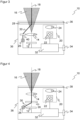
- FIGs 6 to 9 show some exemplary light patterns 42 that can be generated by the aiming device with the light source 26 and the optical metaelement 28.
- Figure 6 A very simple visualization is illustrated in which a point or spot is projected as a light pattern 42 into the center of the field of view 16. This marks the center of the field of view 16 and thus provides a particularly important alignment aid.
- the alignment light 30 is given additional structuring to mark the center, preferably by the optical meta-element 28 itself, alternatively by an additional pattern element or a corresponding arrangement of light sources 26.
- a crosshair is particularly helpful as a light pattern 42, with which the center and the main directions the field of view 16 can be easily recognized. Any other pattern can be projected instead of a crosshair.
- Figure 8 the geometry and extent of the field of view 16 is visualized overall by the light pattern 42. No image of the image sensor 12 is then required in order to correctly align the field of view 16 or the sensor 10 as a whole. Thanks to the coaxial superimposition, the light pattern 42 and its representation of the field of view 16 scale correctly with the imaging scale of the receiving optics 14 over the entire distance range of the sensor 10.
- the receiving optics 14 can be used as well Figures 4 and 5 explained, alternatively the optical metaelement 28 can be used to project the light pattern 42 at the correct size.
- the outer limits of the field of view 16 are in Figure 8 indicated by corner markings; any other patterns are also conceivable here.
- Figure 9 illustrates a combination in which both as in Figure 6 the center of the field of view 16 marked as well as in Figure 8 whose extent is visualized.
- the individual pattern elements can be designed differently, for example as a crosshair, and any pattern can be created in any way that makes important properties of the field of view 16 visible.
Landscapes
- Physics & Mathematics (AREA)
- Engineering & Computer Science (AREA)
- General Physics & Mathematics (AREA)
- Electromagnetism (AREA)
- Health & Medical Sciences (AREA)
- Toxicology (AREA)
- General Health & Medical Sciences (AREA)
- Artificial Intelligence (AREA)
- Computer Vision & Pattern Recognition (AREA)
- Theoretical Computer Science (AREA)
- Optics & Photonics (AREA)
- Multimedia (AREA)
- Signal Processing (AREA)
- Length Measuring Devices By Optical Means (AREA)
Abstract
Description
- Die Erfindung betrifft einen optoelektronischen Sensor, insbesondere eine Kamera, mit einer Zieleinrichtung und ein Verfahren zum Visualisieren des Sichtfeldes eines optoelektronischen Sensors nach dem Oberbegriff von Anspruch 1 beziehungsweise 14.
- In industriellen Anwendungen werden Kameras in vielfältiger Weise eingesetzt, um Objekteigenschaften automatisch zu erfassen, beispielsweise zur Inspektion oder Vermessung von Objekten. Dabei werden Bilder des Objekts aufgenommen und entsprechend der Aufgabe durch Bildverarbeitungsverfahren ausgewertet. Eine besondere Anwendung von Kameras ist das Lesen von Codes. Mit Hilfe eines Bildsensors werden Objekte mit den darauf befindlichen Codes aufgenommen, in den Bildern die Codebereiche identifiziert und dann dekodiert. Kamerabasierte Codeleser kommen problemlos auch mit anderen Codearten als eindimensionalen Strichcodes zurecht, die wie ein Matrixcode auch zweidimensional aufgebaut sind und mehr Informationen zur Verfügung stellen. Auch die automatische Texterfassung von gedruckten Adressen (OCR, Optical Character Recognition) oder Handschriften ist im Prinzip ein Lesen von Codes. Typische Anwendungsgebiete von Codelesern sind Supermarktkassen, die automatische Paketidentifikation, Sortierung von Postsendungen, die Gepäckabfertigung in Flughäfen und andere Logistikanwendungen.
- Eine Kamera nimmt ihre Bilder aus einem Sichtfeld auf. Für eine korrekte Funktion ist erforderlich, das Sichtfeld innerhalb der Anwendungsumgebung auszurichten. Beispielsweise müssen sich zu erfassende Objekte oder lesende Codes im Sichtfeld befinden. Es ist bekannt, die Kamera dafür mit einer Einrichthilfe oder Zieleinrichtung auszustatten, die das Sichtfeld mit einem Fadenkreuz oder einer ähnlichen lokalisierbaren Leuchtmarkierung sichtbar machen.
- In einer herkömmlichen Zieleinrichtung sind Lichtquellen rechts und links des Empfangspfades angeordnet, die mit zwei Spots den mittig dazwischenliegenden Mittelpunkt des Sichtfeldes markieren. Eine zentrale Anordnung einer Lichtquelle ist nicht möglich, weil dort die Lichtquelle einen Teil des Empfangspfades abschatten und somit sprichwörtlich im Bild stehen würde. Der somit bislang erforderliche Einsatz von mehreren Zielstrahlen aus unterschiedlichen Lichtquellen erfordert zusätzliche Bauteile und den entsprechenden Bauraum. Außerdem wird durch das Schielen der Zielstrahlen die Visualisierung des Zentrums des Sichtfelds insbesondere über unterschiedliche Entfernungen hinweg erschwert. Unter Verwendung von Mikrolinsenfeldern oder diffraktiven optischen Elementen ist es möglich, aufwändigere Muster in das Sichtfeld zu projizieren. Die
EP 2 620 894 B1 beispielsweise beschreibt einen optoelektronischen Sensor mit einer Zieleinrichtung, deren Mustererzeugungselement ein Mikrolinsenfeld mit einer Vielzahl von Mikrozylinderlinsen aufweist. Auch solche Mustererzeuger müssen samt der Lichtquellen Raum finden und entsprechend angeleuchtet werden, so dass sich die baulichen und optischen Probleme dadurch nicht auflösen. - Die
DE 20 2015 100 438 U1 offenbart einen optoelektronischen Sensor mit einer Zieleinrichtung, die ein Array von Einzellichtquellen aufweist, die einzeln oder gruppenweise aktiviert werden können, wobei das Aktivierungsmuster dem projizierten Lichtmuster entspricht. Damit lassen sich zwar sehr variabel Lichtmuster erzeugen, der apparative Aufwand wird aber nur vergrößert und ein Schielen nicht verhindert. - Aus der
EP 2 136 248 A1 ist eine Kamera zur Identifikation von Objekten mit einer Objektbeleuchtung und/oder Positionierbeleuchtung bekannt, wobei die Beleuchtung an eine Fokusverstellung gekoppelt ist. Dabei wird das oben erläuterte Konzept mit zwei seitlichen Lichtquellen auf einen Ring von Lichtquellen erweitert und die Lösung damit noch komplexer. - Seit einiger Zeit werden sogenannte Metalinsen eingesetzt. Das sind sind extrem dünne optische Elemente mit Linseneffekt, die spezielle Nanostrukturen aufweisen, um Strahlwege zu beeinflussen. Beispielsweise nutzt die
WO 2017/053309 A1 eine Metalinse zum Kollimieren. Die Arbeit von Yu, Nanfang, und Federico Capasso, "Flat optics with designer metasurfaces." Nature materials 13.2 (2014): 139-150 befasst sich ebenfalls mit dieser Technologie. In der Arbeit von Reshef, Orad, et al. "An optic to replace space and its application towards ultra-thin imaging systems", Nature communications 12.1 (2021): 1-8 werden neben Metalinsen noch sogenannten Spaceplates diskutiert, wobei letztere mit den Metalinsen ähnlichen Technologien auf den Bereich zwischen den Linsen zielen, denn auch mehrere Metalinsen müssen zunächst wie klassische Linsen einen Abstand zueinander einhalten. Diesen Abstand sollen die Spaceplates verringern, um die Bautiefe einer Optik weiter reduzieren zu können. In den bisher vorgeschlagenen Anwendungen werden Metalinsen als Ersatz für klassische, refraktive Linsen verwendet. - Die noch unveröffentlichte
deutsche Patentanmeldung mit dem Aktenzeichen 102021130334.6 vereinigt mittels eines optischen Elements mit wenigstens einer optischen Metaoberfläche einen sichtbaren Pilotlichtstrahl mit einem infraroten Messlichtstrahl. Dadurch kann der Verlauf des Messlichtstrahls mit dem bloßen Auge verfolgt werden. Eine Anwendung als Zieleinrichtung zur Visualisierung des Sichtfeldes einer Kamera ist dort aber nicht angedacht. - Es ist daher Aufgabe der Erfindung, die Zieleinrichtung eines optoelektronischen Sensors zum Sichtbarmachen von dessen Sichtfeld zu verbessern.
- Diese Aufgabe wird durch einen optoelektronischen Sensor mit einer Zieleinrichtung und ein Verfahren zum Visualisieren des Sichtfeldes eines optoelektronischen Sensors nach Anspruch 1 beziehungsweise 14 gelöst. Ein Bildsensor nimmt in seinem Sichtbereich oder Sichtfeld Bilder auf und erfasst entsprechend Bilddaten. Dem Bildsensor ist vorzugsweise eine Empfangsoptik beziehungsweise ein Objektiv vorgeordnet, und gemeinsam bildet dies einen Empfangspfad. Eine Zieleinrichtung mit einer Lichtquelle im sichtbaren Spektrum, beispielsweise einer LED oder einem Laser, erzeugt Ausrichtlicht und damit ein Lichtmuster in dem Sichtfeld, so dass das Sichtfeld für das menschliche Auge erkennbar wird. Um die Position und/oder Ausdehnung des Sichtfeldes sichtbar zu machen, können beispielsweise ein Zentrum, insbesondere mit einem Fadenkreuz, und/oder Grenzlinien oder Ecken markiert werden. Die Lichtquelle ist zu dem Bildsensor lateral, d.h. in dessen Ebene, versetzt angeordnet. Dieser Versatz verhindert, dass die Lichtquelle einen relevanten Teil des Empfangspfades abschattet beziehungsweise in den Bilddaten erfasst wird. Dabei kann die Lichtquelle je nach Ausführungsform in der Ebene des Bildsensors angeordnet sein oder dazu senkrecht, somit in Sichtrichtung der Kamera, einen Abstand aufweisen.
- Die Erfindung geht von dem Grundgedanken aus, ein optisches Metaelement zu verwenden, um die optischen Achsen des Bildsensors und der Zieleinrichtung koaxial zu überlagern. Die optische Achse des Bildsensors ist diejenige des Empfangspfades und einer dort vorzugsweise vorgesehenen Empfangsoptik. Die optische Achse der Zieleinrichtung entspricht deren Abstrahlrichtung in das Sichtfeld hinein. Die Funktion des optischen Metaelements ist somit, den Empfangspfad und die Projektionsachse der Zieleinrichtung koaxial zueinander auszurichten, anders ausgedrückt übereinander zu legen oder in eins zusammenfallen zu lassen. Aufgrund des seitlichen Versatzes der Lichtquelle zu dem Bildsensor ist das anfangs nicht gegeben und wird erst durch das optische Metaelement erreicht.
- Unter einem optischen Metaelement ist ein optisches Element zu verstehen, das eine Metaoberfläche und/oder ein Metamaterial aufweist, d.h. Nanostrukturen insbesondere kleiner als die Wellenlänge des einfallenden Lichts, die ganz gezielt bestimmte Wellenfronten formen. Bei einer Metaoberfläche sind solche Nanostrukturen an der Oberfläche vorgesehen, ein Metamaterial erreicht entsprechende Eigenschaften durch die Nanostruktur eines Schichtsystems oder eines Vollkörpers. Die Nanostrukturen erlauben es, Phase und/oder Amplitude und damit die Ausbreitungsrichtung sowie die Polarisation definiert zu verändern, und dies insbesondere abhängig von der Wellenläge des einfallenden Lichts. Metaoberflächen werden auch als "flache Optiken" bezeichnet, da ihr Platzbedarf in Strahlrichtung deutlich geringer ist als derjenige konventioneller, refraktiver Optiken. Vorzugsweise bildet das optische Metaelement eine Metalinse, d.h. ein flaches, lichtdurchlässiges Trägermaterial mit einer Metaoberfläche an der Vorder- und/oder Rückseite mit einer Nanostruktur, die gewünschte Linseneigenschaften erzielt. Eine Metalinse kann statt eines einfachen Trägermaterials ein Metamaterial aufweisen. Optische Metaelemente sind an sich aus der Fachliteratur bekannt. Einleitend wurden beispielhaft die
WO 2017/053309 A1 sowie die Arbeiten von Yu et al. sowie Reshef et al. kurz vorgestellt, auf die ergänzend verwiesen wird. - Die Erfindung hat den Vorteil, dass das Ausrichtlicht denselben Lichtweg nehmen kann wie das von dem Bildsensor ausgewertete Empfangslicht, natürlich in umgekehrter Richtung. Deshalb treten keine nachteiligen Effekte durch ein Schielen oder dergleichen auf, das Lichtmuster findet sich treu an der richtigen Stelle entsprechend dem Sichtfeld im realen Raum. Insbesondere wird ohne Schwierigkeit der richtige Mittelpunkt des Sichtfelds visualisiert, wobei je nach Anforderungen zusätzlich oder alternativ zur weiteren Unterstützung des Einrichters ebenso das Sichtfeld samt Geometrie und Ausdehnung angezeigt werden kann. Es ist möglich, auf zwei oder mehr Lichtquellen beidseits des Bildsensors zu verzichten und dadurch Bauteile sowie Bauraum einzusparen, der insbesondere bei miniaturisierten Sensoren knapp bemessen ist.
- Vorzugsweise weist der Sensor nur eine Lichtquelle auf. Dank des optischen Metaelements, das die optischen Achsen von Bildsensor und Zieleinrichtung koaxial überlagert, kann trotz der zunächst seitlichen Einstrahlung der zu dem Bildsensor lateral versetzt angeordneten Lichtquelle das Sichtfeld samt dessen Mitte korrekt visualisiert werden. Im Stand der Technik war hierfür eine zur optischen Achse des Bildsensors symmetrische Anordnung mehrerer Lichtquellen erforderlich, wobei nicht einmal damit ein Schielen verhindert werden konnte. Die Erfindung hingegen kann mit einer einzigen Lichtquelle auskommen und projiziert das Lichtmuster dennoch genau in Richtung des Sichtfelds. Alternativ weist der Sensor vorzugsweise mehrere Lichtquellen auf, die eine nicht-symmetrische Anordnung um die optische Achse des Bildsensors bilden. Ein Beispiel hierfür ist eine Doppellichtquelle auf derselben Seite des Bildsensors für mehr Lichtstärke oder ein lateral zum Bildsensor versetzt angeordnetes Lichtquellenarray. Natürlich ist prinzipiell denkbar, auch die Erfindung mit einer symmetrischen Anordnung mehrerer Lichtquellen um die optische Achse des Bildsensors zu kombinieren, aber dann werden die Möglichkeiten des erfindungsgemäß eingesetzten optischen Metaelements nur zum Teil ausgeschöpft.
- Die Lichtquelle weist bevorzugt eine Abstrahlrichtung schräg zu der optischen Achse des Bildsensors auf. Die schräge Abstrahlrichtung führt das Ausrichtlicht vorzugsweise in die optische Achse des Bildsensors. Dort wird es dann durch das optische Metaelement in die Richtung der optischen Achse des Bildsensors umgelenkt, und so werden die optischen Achsen von Bildsensor und Zieleinrichtungen einander koaxial überlagert. Die schräge Abstrahlrichtung korrigiert also gleichsam den lateralen Versatz der Lichtquelle zum Bildsensor.
- In einer bevorzugten Alternative weist die Lichtquelle eine Abstrahlrichtung parallel zu der optischen Achse des Bildsensors auf, wobei ein optisches Element im Strahlengang der Lichtquelle zur Veränderung der Abstrahlrichtung in eine schräge Ausrichtung angeordnet ist. In dieser Ausführungsform weist das Ausrichtlicht anfänglich einen Parallelversatz zur optischen Achse des Bildsensors auf. Das optische Element lenkt das Ausrichtlicht dann in eine schräge Abstrahlrichtung um und führt es vorzugsweise in die optische Achse des Bildsensors. Die Kombination einer parallel zur optischen Achse des Bildsensors abstrahlenden Lichtquelle mit dem optischen Element entspricht funktional einer Lichtquelle mit schräger Abstrahlrichtung wie im Vorabsatz. Die Alternative kann bauliche Vorteile haben, beispielsweise kann es einfacher sein, die internen Lichtwege durch den Sensor zu führen oder eine Lichtquelle auf einer Platine parallel zu der Ebene des Bildsensors mit dazu senkrechter Abstrahlrichtung unterzubringen statt die Lichtquelle schräg anzuordnen. Als optisches Element kommen ein Spiegel, ein Prisma und jegliches sonstige optische Element in Betracht, das ein Lichtbündel umlenken kann. Das optische Element ist im Strahlengang des zunächst parallel zur optischen Achse des Bildsensors ausgesandten Ausrichtlichts angeordnet und damit zum Empfangspfad lateral versetzt, so dass keine Rücksicht auf eine etwaige Beeinflussung von Empfangslicht genommen werden muss.
- Das optische Element ist bevorzugt ein weiteres optisches Metaelement. In dieser Ausführungsform gibt es zwei optische Metaelemente, wobei das weitere optische Metaelement die Umlenkfunktion übernimmt, die im vorigen Absatz beschrieben ist. Diesem nachgeordnet, der Abstrahlrichtung des Ausrichtlichts folgend, ist das erläuterte erfindungsgemäße optische Metaelement, das die optischen Achsen des Bildsensors und der Zieleinrichtung koaxial vereinigt.
- Das optische Element ist bevorzugt dafür ausgebildet, das Ausrichtlicht zu bündeln oder zu kollimieren. Damit erhält das optische Element eine Doppelfunktion der Umlenkung in die schräge Abstrahlrichtung und der Strahlformung des Ausrichtlichts. In einer Ausführungsform als weiteres optisches Metaelement können sowohl die strahlumlenkenden als auch die strahlformenden Eigenschaften durch geeignete Nanostrukturen realisiert werden. Die Strahlformung sorgt dafür, dass das Ausrichtlicht bei der koaxialen Vereinigung der optischen Achsen von Bildsensor und Zieleinrichtung die Strahleigenschaften aufweist, für die das koaxial überlagernde optische Metaelement ausgelegt ist. Es wird dann keine Lichtquelle mit besonderer Abstrahlcharakteristik beziehungsweise keine gesonderte Sendeoptik für die Lichtquelle benötigt, wobei dies natürlich alternativ oder ergänzend denkbar wäre.
- Das optische Metaelement ist bevorzugt dafür ausgebildet, das Lichtmuster zu erzeugen. Neben seiner Funktion der koaxialen Vereinigung wirkt das optische Metaelement somit auch als Mustererzeugungselement. Dadurch lassen sich komplexere Lichtmuster gestalten, wie eine Umrandung des Sichtfelds oder ein Fadenkreuz, und dem Einrichter damit zusätzliche Informationen über Orientierung, Geometrie, Ausdehnung und dergleichen des Sichtfelds geben. Das optische Metaelement kann ebenfalls eine Strahlformungswirkung aufweisen, so dass das Lichtmuster in einem möglichst großen Abstandsbereich scharf projiziert wird. Alternativ ist es denkbar, die Funktionen der Umlenkung beziehungsweise koaxialen Vereinigung und der Mustererzeugung zu trennen und ein zusätzliches Mustererzeugungselement vorzusehen, wie ein diffraktives optisches Element oder ein zusätzliches optisches Metaelement, oder die Lichtquellen sind bereits in einem geeigneten Muster angeordnet, etwa fünf Lichtquellen im Kreuz.
- Dem Bildsensor ist bevorzugt eine Empfangsoptik vorgeordnet, wobei in dieser Reihenfolge Bildsensor, Empfangsoptik und optisches Metaelement hintereinander angeordnet sind. Die koaxiale Zusammenführung der optischen Achsen des Bildsensors und der Zieleinrichtung erfolgt somit aus Sicht des Ausrichtlichts erst hinter der Empfangsoptik. Das Ausrichtlicht umgeht demnach die Empfangsoptik und bleibt davon unbeeinflusst. Die für diese Ausführungsform festgelegte Reihenfolge schließt nicht aus, dass es weitere optische Elemente zwischen Bildsensor und Empfangsoptik oder zwischen Empfangsoptik und optischem Metaelement gibt.
- Das optische Metaelement ist bevorzugt an einer Frontscheibe des Sensors angeordnet, insbesondere in die Frontscheibe integriert. Das ist ein besonders platzsparender Aufbau. Beispielsweise kann eine optische Metaoberfläche innen oder auch außen an der Frontscheibe aufgebracht werden, oder die Frontscheibe besteht zumindest partiell aus einem optischen Metamaterial.
- Dem Bildsensor ist bevorzugt eine Empfangsoptik vorgeordnet, wobei das optische Metaelement zwischen Bildsensor und Empfangsoptik angeordnet ist. In dieser alternativen Ausführungsform ist die Reihenfolge von optischem Metaelement und Empfangsoptik nun vertauscht. Die optischen Achsen des Bildsensors und der Zieleinrichtung werden aus Sicht des Ausrichtlichts bereits vor der Empfangsoptik vereinigt. Das Ausrichtlicht durchdringt die Empfangsoptik, die somit für dessen Strahlformung, insbesondere Bündelung oder Kollimierung, ausgenutzt werden kann. Dadurch kann auf zusätzliche strahlformende optische Elemente der Zieleinrichtung für das Ausrichtlicht verzichtet werden.
- Das optische Metaelement weist bevorzugt eine optische Wirkung nur im Spektrum der Lichtquelle auf, insbesondere nur im sichtbaren Spektrum oder nur für eine Farbe der Lichtquelle. Somit wird gezielt nur das Ausrichtlicht abgelenkt beziehungsweise strahlgeformt oder damit ein Lichtmuster geformt. Licht mit Wellenlängen außerhalb des Spektrums der Lichtquelle hingegen, und damit alles oder jedenfalls das meiste Empfangslicht, wird einfach unverändert durchgelassen. Dies ist nur in den Grenzen des technisch Machbaren möglich, aber eine Metaoberfläche oder ein Metamaterial kann durchaus so ausgelegt werden, dass die Wirkung außerhalb eines bestimmten Spektralbandes vernachlässigbar bleibt. Das Spektrum der Lichtquelle, innerhalb dessen das optische Metaelement eine optische Wirkung zeigt, kann das ganze sichtbare Spektrum sein. Das genügt für die Abgrenzung zwischen Ausrichtlicht und Empfangslicht, wenn die Bilddaten im nicht sichtbaren Bereich gewonnen werden, etwa Aufnahmen im infraroten oder ultravioletten Bereich erfolgen. Besonders bevorzugt erzeugt die Lichtquelle Ausrichtlicht in nur einer Farbe, etwa in blau, dies vorzugsweise kombiniert mit dem gewinnen von Bilddaten in einer anderen Farbe, etwa in rot. In diesem Zusammenhang darf Farbe insbesondere auch im Sinne des besonders schmalen Wellenlängenbereichs einer Laserlichtquelle verstanden werden. Sofern es Überschneidungen im Spektrum der Zieleinrichtung und des Bildsensors gibt, bleibt durch ein enges Wirkspektrum des optischen Metaelements die Wechselwirkung klein und hinnehmbar. Das Empfangslicht wird nur wenig beeinflusst, die Bilddaten sind allenfalls geringfügig verändert.
- Der Sensor weist bevorzugt eine Beleuchtungseinrichtung zum Ausleuchten des Sichtfeldes auf, die insbesondere Beleuchtungslicht in einem anderen Spektralbereich erzeugt als das Ausrichtlicht der Lichtquelle. Diese Beleuchtungseinrichtung dient nicht der Visualisierung des Sichtfelds, sondern der ausreichenden Beleuchtung für die Bildaufnahme. Die Beleuchtungseinrichtung kann intern oder extern sein, und vorzugsweise wird Beleuchtungslicht außerhalb des sichtbaren Spektrums erzeugt, insbesondere infrarotes oder ultraviolettes Beleuchtungslicht. Durch eine spektrale Trennung zwischen Beleuchtungslicht und Ausrichtlicht kann das optische Metaelement seine verschiedenen Funktionen erfüllen, nämlich das Ausrichtlicht koaxial mit dem Empfangspfad vereinigen und Beleuchtungslicht beziehungsweise entsprechendes zurückkehrendes Empfangslicht möglichst gar nicht beeinflussen.
- Der Sensor ist bevorzugt als kamerabasierter Codeleser ausgebildet und weist eine Steuer- und Auswertungseinheit zur Auswertung der Bilddaten, zum Auffinden von Codebereichen und zum Auslesen von Codeinformationen aus den Codebereichen auf. Die Zieleinrichtung ermöglicht für einen kamerabasierten Codeleser, dessen Lesefeld optimal auszurichten. Dies ist sowohl für Codeleser im Handbetrieb wie auch für Codeleser in fixer Montage etwa an einem Förderband oder in einem Lesetunnel wichtig, um möglichst alle Codes zu lesen.
- Das erfindungsgemäße Verfahren kann auf ähnliche Weise weitergebildet werden und zeigt dabei ähnliche Vorteile. Derartige vorteilhafte Merkmale sind beispielhaft, aber nicht abschließend in den sich an die unabhängigen Ansprüche anschließenden Unteransprüchen beschrieben.
- Die Erfindung wird nachstehend auch hinsichtlich weiterer Merkmale und Vorteile beispielhaft anhand von Ausführungsformen und unter Bezug auf die beigefügte Zeichnung näher erläutert. Die Abbildungen der Zeichnung zeigen in:
- Fig. 1
- eine schematische Darstellung eines optoelektronischen Sensors mit einem Bildsensor und einer Zieleinrichtung, deren optische Achsen mittels eines optischen Metaelements koaxial überlagert werden;
- Fig. 2
- eine Darstellung ähnlich
Figur 1 nun mit Anordnung des optischen Metaelements an einer Frontscheibe; - Fig. 3
- eine Darstellung ähnlich
Figur 2 nun mit anfänglich paralleler statt schräger Abstrahlrichtung der Zieleinrichtung; - Fig. 4
- eine Darstellung ähnlich
Figur 1 nun mit vertauschter Reihenfolge von Empfangsoptik und optischem Metaelement; - Fig. 5
- eine Darstellung ähnlich
Figur 4 nun mit anfänglich paralleler statt schräger Abstrahlrichtung der Zieleinrichtung; - Fig. 6
- eine beispielhafte Visualisierung eines Sichtfelds durch Markierung des Zentrums;
- Fig. 7
- eine beispielhafte Visualisierung eines Sichtfelds durch Markierung des Zentrums mit einem Fadenkreuz;
- Fig. 8
- eine beispielhafte Visualisierung eines Sichtfelds durch Markierung der Eckbereiche; und
- Fig. 9
- eine beispielhafte Visualisierung eines Sichtfelds durch Markierung des Zentrums und der Eckbereiche.
-
Figur 1 zeigt eine schematische Schnittdarstellung eines optoelektronischen Sensors 10. Der Sensor 10 weist einen Bildsensor 12 auf, beispielsweise einen CCD- oder CMOS-Chip mit einer Vielzahl von zu einer Zeile oder einer Matrix angeordneten Pixelelementen. Somit handelt es sich bei dem Sensor 10 insbesondere um eine Kamera. In einer bevorzugten Ausführungsform werden Codes gelesen, der Sensor 10 ist dann ein kamerabasierter Codeleser. Dem Bildsensor 12 ist eine Empfangsoptik 14 vorgeordnet, die in der Praxis vorzugsweise als Aufnahmeobjektiv ausgebildet ist und hier vereinfacht durch nur eine Linse dargestellt ist. Der Bildsensor 12 empfängt über die Empfangsoptik 14 Empfangslicht aus einem Sichtbereich oder Sichtfeld 16, in dem sich in der Anwendungssituation die aufzunehmenden Objekte und insbesondere zu lesende Codes befinden. Das Sichtfeld 16 sowie eine optische Achse 18 des Empfangspfades werden durch die Auslegung und Anordnung von Bildsensor 12 und Empfangsoptik 14 definiert. Etwas ungenau wird in dieser Beschreibung häufig von Sichtfeld 16 und optischer Achse 18 des Bildsensors 12 gesprochen. - Um Bilder unabhängig von Umgebungsbedingungen aufzunehmen, weist der Sensor 10 vorzugsweise eine Beleuchtung 20 mit einem Lichtsender 22, der eine Vielzahl von Einzellichtsendern aufweisen kann, und vorzugsweise einer Sendeoptik 24 auf. Die Beleuchtung 20 kann wie dargestellt intern und alternativ extern vorgesehen sein, ihre Ausgestaltung ist in jeder an sich bekannten Weise möglich. Die Anordnung der Beleuchtung 20 bezüglich des Empfangspfades mit dem Bildsensor 12 wie in
Figur 1 ist denkbar, jedoch in erster Linie schematisch zu verstehen, in der Praxis werden beispielsweise Lichtsender 22 kreisförmig um den Empfangspfad angeordnet. Vorzugsweise erzeugt der Lichtsender 22 Beleuchtungslicht im nicht sichtbaren Spektrum, insbesondere infrarotes oder ultraviolettes Beleuchtungslicht. Eine Beleuchtung im sichtbaren Spektrum, wie weißes, rotes, blaues oder grünes Licht ist aber nicht ausgeschlossen. Der Lichtsender kann überdies schmalbandig sein, wie im Falle einer LED oder vor allem eines Lasers. - Der Sensor 10 umfasst weiterhin eine Zieleinrichtung mit einer Lichtquelle 26, etwa einer Halbleiterlichtquelle wie eine LED, eine Laserdiode oder ein VCSEL im sichtbaren Spektrum, und einem optischen Metaelement 28. Die Lichtquelle 26 ist zu dem Bildsensor 12 lateral versetzt angeordnet, weist also einen Abstand zu der optischen Achse 18 des Bildsensors 12 auf. Die Lichtquelle 26 kann auch wie dargestellt einen Abstand in Richtung der optischen Achse 18 aufweisen, oder sie befindet sich abweichend in der Ebene des Bildsensors 12. In einer bevorzugten Ausführungsform genügt eine einzige Lichtquelle 26, es sind aber auch mehrere Lichtquellen 26 denkbar. Diese sind dann vorzugsweise in einer nicht-symmetrischen Weise zu dem Bildsensor 12 angeordnet, das Ausrichtlicht 30 ist somit anfänglich bezüglich der optischen Achse 18 nicht zentriert.
- Die Lichtquelle 26 strahlt ihr Ausrichtlicht 30 zunächst bezüglich der optischen Achse 18 mit einer schrägen Abstrahlrichtung ab. Das Ausrichtlicht 30 trifft aufgrund der Schrägstellung auf die optische Achse 18 und hier auf das optische Metaelement 28. Das optische Metaelement 28 ist so ausgelegt, dass es im Spektrum des Ausrichtlichts 30 für eine Umlenkung auf die optische Achse 18 sorgt. Die Abstrahlrichtung wird also mit der optischen Achse 18 und damit der Einfallsrichtung des Empfangslichts ausgerichtet. Anders ausgedrückt werden die optische Achse der Zieleinrichtung und die optische Achse 18 des Bildsensors 12 beziehungsweise des Empfangspfades koaxial überlagert oder vereinigt.
- Mit der Zieleinrichtung wird in dem Sichtfeld 16 mit dem Ausrichtlicht 30 ein Lichtmuster erzeugt, das einem menschlichen Betrachter wie dem Einrichter des Sensors 10 die Lage des Sichtfelds 16 anzeigt oder im realen Raum visualisiert. Somit kann der Sensor einfach auf eine Szenerie beziehungsweise aufzunehmende Objekte oder Codes ausgerichtet werden. Dank der koaxialen Überlagerung von Zieleinrichtung und Empfangspfad zeigt das Lichtmuster den richtigen Bezug zum Sichtfeld 16 im realen Raum an. Das Lichtmuster kann einfach oder komplex sein, später werden unter Bezugnahme auf die
Figuren 6 bis 9 Beispiele erläutert. Das optische Metaelement 28 kann neben seiner Umlenkfunktion für die Mustererzeugung ausgebildet sein, oder es ist dafür ein gesondertes, nicht gezeigtes Mustererzeugungselement zuständig, oder das Lichtmuster besteht nur aus einem oder wenigen Lichtspots, die unmittelbar von der Lichtquelle 26 erzeugt werden. - Das optische Metaelement 28 weist eine Metaoberfläche auf und ist insbesondere als Metalinse aufgebaut ("flat optics"). Alternativ oder ergänzend ist denkbar, dass bereits der Körper oder Träger des optischen Metaelements 28 ein Metamaterial aufweist. Herkömmliche optische Komponenten wie Linsen, Wellenplatten oder Hologramme beruhen auf der Lichtausbreitung über Entfernungen, die viel größer als die Wellenlänge des einfallenden Lichts sind, um Wellenfronten zu formen. Auf diese Weise werden entlang des Strahlengangs nach und nach wesentliche Änderungen der Amplitude, Phase oder Polarisation von Lichtwellen akkumuliert. Eine Metaoberfläche hingegen weist Strukturen auf, die als Miniatur-Anisotrop-Lichtstreuer oder Resonatoren beziehungsweise optische Antennen aufgefasst werden können. Diese Strukturen haben Abmessungen und Abstände im Nanometerbereich, viel kleiner als die Wellenlänge des einfallenden Lichts. Dadurch formt die Metaoberfläche nach dem Huygens-Prinzip optische Wellenfronten in beliebige Formen mit Subwellenlängenauflösung, indem die Nanostrukturen räumliche Variationen in der optischen Reaktion der Lichtstreuer einführen. Damit lassen sich Effekte einer herkömmlichen Linse nachempfinden, aber auch Funktionalitäten von anderen optischen Komponenten, wie beispielsweise von Strahlumlenkelementen, Strahlteilern, Polarisatoren oder Beugungsgittern. Die Besonderheit ist die hohe Flexibilität, durch angepasste Nanostrukturen eine gewünschte Ausgangswellenfront und damit verschiedenste optische Effekte zu erreichen. Je nach Wellenlängenbereich werden Materialien mit einem geeigneten Transmissionsverhalten verwendet, beispielsweise Titandioxid, Siliziumnitrid oder Galliumphosphid im sichtbaren und Aluminiumnitrid im ultravioletten Spektralbereich sowie Chalkogenid-Legierungen im mittleren und Silizium im langwelligen Infrarotbereich. Diese Überlegungen zu einer Metaoberfläche lassen sich auf ein Metamaterial übertragen, bei dem das Innere beziehungsweise der Träger entsprechende Nanostrukturen aufweist, wobei dies mit einer Metaoberfläche kombinierbar ist. Das optische Metaelement 28 kann folglich eine Meta- oder Nanostruktur im Inneren und/oder auf der Vorder- und/oder Rückseite aufweisen. Für an sich bekannte Eigenschaften eines optischen Metaelements 28 wird nochmals auf die Fachliteratur und insbesondere die einleitend genannte
WO 2017/053309 A1 sowie die Arbeiten von Yu et al. und Reshef et al. verwiesen. - Erfindungsgemäß ist die gewünschte Funktion des optischen Metaelements 28 in erster Linie eine Umlenkung zur koaxialen Überlagerung von Zieleinrichtung und Empfangspfad, gegebenenfalls mit einer zusätzlichen Mustererzeugung und/oder Strahlformung, Bündelung oder Kollimierung. Vorzugsweise wirkt das optische Metaelement gezielt nur im Spektrum der Lichtquelle 26 und damit nur auf das Ausrichtlicht 30, nicht aber auf das Beleuchtungslicht des Lichtsenders 22 der Beleuchtung 20 beziehungsweise das Empfangslicht. Das optische Metaelement 28 ist damit im Empfangspfad praktisch unsichtbar. Eine spektrale Trennung ist beispielsweise dann möglich, wenn der Bildsensor 12 im nicht sichtbaren Spektrum aufnimmt, dementsprechend die Beleuchtung 20 beispielsweise infrarotes oder ultraviolettes Beleuchtungslicht erzeugt. Auch eine Trennung im sichtbaren Bereich ist vorstellbar, beispielsweise blaues Ausrichtlicht 30 bei rotem Beleuchtungslicht beziehungsweise roter Bildaufnahme.
- Sofern sich eine spektrale Überlagerung nicht vermeiden lässt, ist es vorteilhaft, eine besonders schmalbandige Lichtquelle 26 einzusetzen, insbesondere eine Laserlichtquelle, und das optische Metaelement 28 darauf abzustimmen. Das Empfangslicht wird dann nur minimal beeinflusst, und ferner ist denkbar, vor dem Bildsensor 12 ein entsprechendes optisches Filter anzuordnen, mit dem Licht im Spektrum des Ausrichtlichts 30 herausgefiltert wird. Damit werden auch Kombinationen mit eng zusammenliegenden Wellenlängen möglich. Beispielsweise kann die Beleuchtung 20 eine weiße LED oder eine nahinfrarote Lichtquelle als Lichtsender 22 einsetzen, und die Zieleinrichtung eine rote Lichtquelle 26, insbesondere einen entsprechenden Laser. Da die Zieleinrichtung in der Regel mit ausgeschalteter Beleuchtung 20 betrieben wird, ist die Sichtbarkeit des Lichtmusters unproblematisch. Selbst bei eingeschalteter Beleuchtung 20 kann sich das Lichtmuster bei ausreichender Beleuchtungsstärke der Lichtquelle 26 in deren Spektrum ausreichend abheben.
- Der Sensor 10 weist weiterhin eine Steuer- und Auswertungseinheit 32 auf. Damit werden die Beleuchtung 20 und die Lichtquelle 26 der Zieleinrichtung angesteuert und die Bilddaten des Bildsensors 12 ausgelesen. In einer Ausführungsform des Sensors 10 als kamerabasierter Codeleser werden in den Bilddaten Codebereiche gesucht, und die Codeinformationen innerhalb von Codebereichen werden dekodiert. Bilddaten, Ergebnisse einer Auswertung wie Codeinformationen und dergleichen werden an einer Schnittstelle 34 bereitgestellt. Es können Bilddaten in unterschiedlichen Vorverarbeitungsstadien ausgegeben und die gesamte Auswertung oder ein Teil der Auswertung nach extern verlagert werden.
- Der Sensor 10 wird durch ein Gehäuse 36 geschützt, das in vielen Ausführungsformen an einer Seite mindestens partiell durch eine transparente Frontscheibe 38 abgeschlossen wird.
- Die
Figuren 2 bis 5 zeigen weitere Ausführungsformen der Erfindung, die sich von der zuFigur 1 beschriebenen Ausführungsform durch ihre Einkoppelszenarien unterscheiden, also die jeweilige Anordnung und Auslegung der Lichtquelle 26 und des optischen Metaelements 28, um das Ausrichtlicht 30 auf die optische Achse 18 zu führen und damit die koaxiale Überlagerung der optischen Achse 18 des Empfangspfads und der optischen Achse der Zieleinrichtung zu erreichen. Es werden im Folgenden in erster Linie die Unterschiede beschrieben und dabei die bereits bekannten Merkmale und Eigenschaften mit denselben Bezugszeichen versehen. -
Figur 2 zeigt eine Ausführungsform, in der die Einkopplung des Ausrichtlichts 30 auf die optische Achse 18 an der Frontscheibe 38 erfolgt. Dazu ist das optische Metaelement 28 innen oder außen an der Frontscheibe 38 angeordnet oder in die Frontscheibe 38 integriert. Die Abstrahlrichtung der Lichtquelle 26 und insbesondere deren Schrägstellung ist entsprechend angepasst, um auf die veränderte Position des optischen Metaelements 28 zu zielen. Die Kombination von optischem Metaelement 28 und Frontscheibe 38 verringert die Anzahl der Bauteile und beansprucht weniger Bauraum. -
Figur 3 zeigt eine Ausführungsform, in der weiterhin das optische Metaelement 28 zur koaxialen Überlagerung des Ausrichtlichts 30 auf die optische Achse 18 an der Frontscheibe 38 angeordnet oder in die Frontscheibe 38 integriert ist. Zudem ist nun die Abstrahlrichtung der Lichtquelle 26 nicht mehr schräg, sondern parallel zur optischen Achse 18. Um das Ausrichtlicht 30 auf Höhe des optischen Metaelements 28 auf die optische Achse 18 zu führen, ist ein weiteres optisches Element 40 zur Umlenkung vorgesehen. Die Kombination der parallel ausgerichteten Lichtquelle 26 mit dem weiteren optischen Element 40 bewirkt somit effektiv die gleiche Abstrahlrichtung wie ein zuvor beschriebenes Schrägstellen der Lichtquelle 26. - Das weitere optische Element 40 kann irgendein Umlenkelement sein, wie ein Spiegel oder ein Prisma. Das weitere optische Element 40 liegt wegen des lateralen Versatzes der Lichtquelle 26 zum Bildsensor 12 außerhalb des Sichtfelds 16, so dass besondere Eigenschaften hinsichtlich der Transparenz im Spektrum der Beleuchtung 20 beziehungsweise des Empfangslichts nicht gefordert sind. Bevorzugt handelt es sich bei dem weiteren optischen Element 40 um ein weiteres optisches Metaelement, das im Spektrum des Ausrichtlichts 30 für die gewünschte Umlenkung sorgt. Besonders bevorzugt ist das weitere optische Element 40 für eine Strahlformung des Ausrichtlichts 30 ausgebildet, insbesondere zu dessen Kollimierung. In einer Ausführungsform als weiteres optisches Metaelement kann von dessen Nanostrukturen neben einer linearen Phase zur Strahlumlenkung gleichzeitig eine auf die gewünschten Abbildungseigenschaften angepasste Phasenkrümmung erzeugt werden. Bei einer derartigen Doppelfunktion des weiteren optischen Elements 40 kann eine divergente Lichtquelle 26 eingesetzt beziehungsweise auf eine gesonderte Strahlformungs- oder Kollimationsoptik für die Lichtquelle 26 verzichtet werden. Abweichend von
Figur 3 könnte das optische Metaelement 28 wie inFigur 1 einzeln statt an der Frontscheibe 38 vorgesehen sein. -
Figur 4 zeigt eine Ausführungsform, in der die Positionen von Empfangsoptik 14 und optischem Metaelement 28 gegenüber den bisherigen Ausführungsformen vertauscht sind. Während das Ausrichtlicht 30 bisher die Empfangsoptik 14 umgangen hat, tritt es in der Ausführungsform gemäßFigur 4 durch die Empfangsoptik 14. Somit kann die Empfangsoptik 14 von der Zieleinrichtung mit genutzt werden, um das Ausrichtlicht 30 strahlzuformen oder zu kollimieren. Das optische Metaelement 28 kann die strahlformenden Eigenschaften der Empfangsoptik 14 für das Ausrichtlicht 30 ergänzen, also neben einer reinen Umlenkung durch eine lineare Phase eine passende Phasenkrümmung einführen. In einerweiteren Ausführungsform wird das optische Metaelement28 in die Empfangsoptik 28 integriert, beispielsweise als Metaoberfläche einer Linse. In der Ausführungsform gemäßFigur 4 ist die Lichtquelle 26 wie in denFiguren 1 und 2 unter einem Winkel angeordnet oder schräg gestellt, um auf das optische Metaelement 28 zu zielen, wo dann das Ausrichtlicht 30 koaxial mit der optischen Achse 18 überlagert wird, ehe es die Empfangsoptik 14 erreicht. -
Figur 5 zeigt eine Ausführungsform ähnlichFigur 4 , also mit koaxialer Überlagerung bereits vor der Empfangsoptik 14, wobei nun die Lichtquelle 26 nicht mehr schräg steht, sondern wie inFigur 3 parallel zu der optischen Achse 18 abstrahlt. Wie zuFigur 3 erläutert, ist ein weiteres optisches Element 40 vorgesehen, das das Ausrichtlicht 30 auf das optische Metaelement 28 umlenkt. Das weitere optische Element 40 ist vorzugsweise ein weiteres optisches Metaelement. - Die
Figuren 6 bis 9 zeigen einige beispielhafte Lichtmuster 42, die von der Zieleinrichtung mit der Lichtquelle 26 und dem optischen Metaelement 28 erzeugt werden können. InFigur 6 ist eine sehr einfache Visualisierung illustriert, in der ein Punkt oder Spot als Lichtmuster 42 in das Zentrum des Sichtfelds 16 projiziert wird. Dadurch ist das Zentrum des Sichtfelds 16 markiert und damit eine besonders wichtige Ausrichthilfe gegeben. - In
Figur 7 wird dem Ausrichtlicht 30 zur Markierung des Zentrums eine zusätzliche Strukturierung mitgegeben, vorzugsweise durch das optische Metaelement 28 selbst, alternativ durch ein zusätzliches Musterelement oder eine entsprechende Anordnung von Lichtquellen 26. Besonders hilfreich ist ein Fadenkreuz als Lichtmuster 42, mit dem das Zentrum und die Hauptrichtungen des Sichtfelds 16 leicht erkennbar werden. Anstelle eines Fadenkreuzes kann ein beliebiges anderes Muster projiziert werden. - In
Figur 8 wird durch das Lichtmuster 42 die Geometrie und Ausdehnung des Sichtfeldes 16 insgesamt visualisiert. Es ist dann kein Bild des Bildsensors 12 erforderlich, um das Sichtfeld 16 beziehungsweise den Sensor 10 insgesamt korrekt auszurichten. Das Lichtmuster 42 und dessen Darstellung des Sichtfeldes 16 skaliert dank der koaxialen Überlagerung korrekt mit dem Abbildungsmaßstab der Empfangsoptik 14 über den gesamten Abstandsbereich des Sensors 10. Für diese größentreue Darstellung des Sichtfelds 16 kann die Empfangsoptik 14 mitgenutzt werden wie zu denFiguren 4 und5 erläutert, alternativ kann das optische Metaelement 28 verwendet werden, um das Lichtmuster 42 in der richtigen Größe zu projizieren. Die Außengrenzen des Sichtfeldes 16 werden inFigur 8 durch Eckmarkierungen angezeigt, auch hier sind beliebige andere Muster denkbar. -
Figur 9 illustriert eine Kombination, in der sowohl wie inFigur 6 das Zentrum des Sichtfeldes 16 markiert als auch wie inFigur 8 dessen Ausdehnung visualisiert wird. Die einzelnen Musterelemente können anders gestaltet werden, beispielsweise jeweils als Fadenkreuz, und überhaupt abweichend beliebige Muster erzeugt werden, die wichtige Eigenschaften des Sichtfelds 16 sichtbar machen.
Claims (14)
- Optoelektronischer Sensor (10), insbesondere Kamera, der einen Bildsensor (12) zur Erfassung von Bilddaten in seinem Sichtfeld (16) und eine Zieleinrichtung (26, 28) mit einer Lichtquelle (26) aufweist, die seitlich versetzt zu dem Bildsensor (12) angeordnet und dafür ausgebildet ist, Ausrichtlicht (30) und damit ein Lichtmuster (42) in dem Sichtfeld (16) zu erzeugen, um die Position und/oder Ausdehnung des Sichtfeldes (16) im Raum sichtbar zu machen, dadurch gekennzeichnet,
dass die Zieleinrichtung (26, 28) mindestens ein optisches Metaelement (28) mit einer Metaoberfläche und/oder einem Metamaterial aufweist, das derart angeordnet und ausgebildet ist, dass die optischen Achsen (18, 30) von Bildsensor (12) und Zieleinrichtung (26, 28) koaxial überlagert werden. - Sensor (10) nach Anspruch 1,
der nur eine Lichtquelle (26) aufweist oder der mehrere Lichtquellen (26) aufweist, die eine nicht-symmetrische Anordnung um die optische Achse (18) des Bildsensors (12) bilden. - Sensor (10) nach Anspruch 1 oder 2,
wobei die Lichtquelle (26) eine Abstrahlrichtung schräg zu der optischen Achse (18) des Bildsensors (12) aufweist. - Sensor (10) nach Anspruch 1 oder 2,
wobei die Lichtquelle (26) eine Abstrahlrichtung parallel zu der optischen Achse (18) des Bildsensors (12) aufweist, und wobei ein optisches Element (40) im Strahlengang der Lichtquelle (26) zur Veränderung der Abstrahlrichtung in eine schräge Ausrichtung angeordnet ist. - Sensor (10) nach Anspruch 4,
wobei das optische Element (40) ein weiteres optisches Metaelement ist. - Sensor (10) nach Anspruch 4 oder 5,
wobei das optische Element (40) dafür ausgebildet ist, das Ausrichtlicht (30) zu bündeln oder kollimieren. - Sensor (10) nach einem der vorhergehenden Ansprüche,
wobei das optische Metaelement (28) dafür ausgebildet ist, das Lichtmuster (42) zu erzeugen. - Sensor (10) nach einem der vorhergehenden Ansprüche,
wobei dem Bildsensor (12) eine Empfangsoptik (14) vorgeordnet ist, und wobei in dieser Reihenfolge Bildsensor (12), Empfangsoptik (14) und optisches Metaelement (28) hintereinander angeordnet sind. - Sensor (10) nach einem der vorhergehenden Ansprüche,
wobei das optische Metaelement (28) an einer Frontscheibe (38) des Sensors (10) angeordnet, insbesondere in die Frontscheibe (38) integriert ist. - Sensor (10) nach einem der Ansprüche 1 bis 7,
wobei dem Bildsensor (12) eine Empfangsoptik (14) vorgeordnet ist, und wobei das optische Metaelement (28) zwischen Bildsensor (12) und Empfangsoptik (18) angeordnet ist. - Sensor (10) nach einem der vorhergehenden Ansprüche,
wobei das optische Metaelement (28) eine optische Wirkung nur im Spektrum der Lichtquelle (26) aufweist, insbesondere nur im sichtbaren Spektrum oder nur für eine Farbe der Lichtquelle (26). - Sensor (10) nach einem der vorhergehenden Ansprüche,
der eine Beleuchtungseinrichtung (20) zum Ausleuchten des Sichtfeldes (16) aufweist, die insbesondere Beleuchtungslicht in einem anderen Spektralbereich erzeugt als das Ausrichtlicht (30) der Lichtquelle (26). - Sensor (10) nach einem der vorhergehenden Ansprüche,
der als kamerabasierter Codeleser ausgebildet ist und eine Steuer- und Auswertungseinheit (32) zur Auswertung der Bilddaten, zum Auffinden von Codebereichen und zum Auslesen von Codeinformationen aus den Codebereichen aufweist. - Verfahren zum Visualisieren des Sichtfeldes (16) eines optoelektronischen Sensors (10), insbesondere eines optoelektronischen Sensors (10) nach einem der vorhergehenden Ansprüche, der mit einem Bildsensor (12) Bilddaten aus dem Sichtfeld (16) erfasst und mittels einer Zieleinrichtung (26, 28) mit einer seitlich versetzt zu dem Bildsensor (12) angeordneten Lichtquelle (26) Ausrichtlicht (30) abstrahlt und damit ein Lichtmuster (42) in dem Sichtfeld (16) erzeugt, um die Position und/oder Ausdehnung des Sichtfeldes (16) im Raum sichtbar zu machen,
dadurch gekennzeichnet,
dass die Zieleinrichtung (26, 28) mindestens ein optisches Metaelement (28) mit einer Metaoberfläche und/oder einem Metamaterial aufweist, das die optischen Achsen (18, 30) von Bildsensor (12) und Zieleinrichtung (26, 28) koaxial überlagert.
Priority Applications (5)
| Application Number | Priority Date | Filing Date | Title |
|---|---|---|---|
| ES22165310T ES2985457T3 (es) | 2022-03-30 | 2022-03-30 | Sensor optoelectrónico con un dispositivo de apuntamiento y procedimiento para visualizar un campo de visión |
| EP22165310.8A EP4254063B1 (de) | 2022-03-30 | 2022-03-30 | Optoelektronischer sensor mit einer zieleinrichtung und verfahren zum visualisieren eines sichtfeldes |
| KR1020220174703A KR102782769B1 (ko) | 2022-03-30 | 2022-12-14 | 조준 장치를 구비한 광전자 센서 및 시야를 가시화하기 위한 방법 |
| US18/083,688 US11977950B2 (en) | 2022-03-30 | 2022-12-19 | Optoelectronic sensor having an aiming device and method of visualizing a field of view |
| CN202310124821.5A CN116896680A (zh) | 2022-03-30 | 2023-02-16 | 具有照准器的光电传感器和用于可视化视场的方法 |
Applications Claiming Priority (1)
| Application Number | Priority Date | Filing Date | Title |
|---|---|---|---|
| EP22165310.8A EP4254063B1 (de) | 2022-03-30 | 2022-03-30 | Optoelektronischer sensor mit einer zieleinrichtung und verfahren zum visualisieren eines sichtfeldes |
Publications (3)
| Publication Number | Publication Date |
|---|---|
| EP4254063A1 true EP4254063A1 (de) | 2023-10-04 |
| EP4254063B1 EP4254063B1 (de) | 2024-05-15 |
| EP4254063C0 EP4254063C0 (de) | 2024-05-15 |
Family
ID=81327955
Family Applications (1)
| Application Number | Title | Priority Date | Filing Date |
|---|---|---|---|
| EP22165310.8A Active EP4254063B1 (de) | 2022-03-30 | 2022-03-30 | Optoelektronischer sensor mit einer zieleinrichtung und verfahren zum visualisieren eines sichtfeldes |
Country Status (5)
| Country | Link |
|---|---|
| US (1) | US11977950B2 (de) |
| EP (1) | EP4254063B1 (de) |
| KR (1) | KR102782769B1 (de) |
| CN (1) | CN116896680A (de) |
| ES (1) | ES2985457T3 (de) |
Families Citing this family (1)
| Publication number | Priority date | Publication date | Assignee | Title |
|---|---|---|---|---|
| CN117705061A (zh) * | 2022-09-08 | 2024-03-15 | 香港城市大学 | 复合光学系统及深度检测系统 |
Citations (8)
| Publication number | Priority date | Publication date | Assignee | Title |
|---|---|---|---|---|
| US20060000911A1 (en) * | 2002-05-07 | 2006-01-05 | Amit Stekel | Automatic certification, identification and tracking of remote objects in relative motion |
| DE102005040056A1 (de) * | 2004-08-25 | 2006-03-09 | Denso Wave Inc. | Vorrichtung zum optischen Lesen von Informationen |
| EP2136248A1 (de) | 2008-06-20 | 2009-12-23 | Sick Ag | Bildaufnahmevorrichtung mit anpassbarer Beleuchtung |
| EP2620894B1 (de) | 2012-01-26 | 2014-01-08 | Sick AG | Optoelektronischer Sensor und Verfahren zur Erfassung von Objektinformationen |
| DE202015100438U1 (de) | 2015-01-30 | 2016-05-03 | Sick Ag | Optoelektronischer Sensor zur Erfassung von Objektinformationen |
| DE102015115016A1 (de) * | 2015-09-08 | 2017-03-09 | Leuze Electronic Gmbh + Co. Kg | Lichtkontrasttaster |
| WO2017053309A1 (en) | 2015-09-23 | 2017-03-30 | Osram Sylvania Inc. | Collimating metalenses and technologies incorporating the same |
| EP3205972A1 (de) * | 2016-02-10 | 2017-08-16 | Rosemount Aerospace Inc. | Metasurface-optik für dual-mode-suchkopf |
Family Cites Families (12)
| Publication number | Priority date | Publication date | Assignee | Title |
|---|---|---|---|---|
| DE502004003840D1 (de) * | 2003-03-24 | 2007-06-28 | Kaltenbach & Voigt | Röntgengerät |
| US8599301B2 (en) * | 2006-04-17 | 2013-12-03 | Omnivision Technologies, Inc. | Arrayed imaging systems having improved alignment and associated methods |
| US10346645B1 (en) * | 2013-03-12 | 2019-07-09 | Cognex Corporation | On-axis aimer for vision system and multi-range illuminator for same |
| US20190353830A1 (en) * | 2018-05-17 | 2019-11-21 | Purdue Research Foundation | Tunable plasmonic color device and method of making the same |
| US10922828B2 (en) * | 2017-07-31 | 2021-02-16 | Samsung Electronics Co., Ltd. | Meta projector and electronic apparatus including the same |
| DE112018006420T5 (de) * | 2017-12-18 | 2020-09-17 | Seeing Machines Limited | Hochleistungsabbildungssystem unter Verwendung einer dielektrischen Metaoberfläche |
| US10769394B2 (en) * | 2018-03-22 | 2020-09-08 | Symbol Technologies, Llc | Devices systems and methods for alignment of lens assemblies within a chassis |
| CN109061780B (zh) * | 2018-09-11 | 2020-07-21 | 鲁东大学 | 一种双波长同轴独立聚焦的超表面透镜 |
| US10970503B2 (en) * | 2018-10-25 | 2021-04-06 | Zebra Technologies Corporation | Imaging arrangements and barcode readers including such imaging arrangements |
| CN213122292U (zh) * | 2020-06-03 | 2021-05-04 | 镭沃光电(东莞)有限公司 | 成像设备、共光轴测距成像装置及其共光轴测距成像系统 |
| CN113807312B (zh) * | 2021-09-30 | 2024-10-18 | 深圳迈塔兰斯科技有限公司 | 超表面及具有其的指纹识别装置 |
| DE102021130334A1 (de) | 2021-11-19 | 2023-05-25 | Sick Ag | Optoelektronischer Sensor |
-
2022
- 2022-03-30 ES ES22165310T patent/ES2985457T3/es active Active
- 2022-03-30 EP EP22165310.8A patent/EP4254063B1/de active Active
- 2022-12-14 KR KR1020220174703A patent/KR102782769B1/ko active Active
- 2022-12-19 US US18/083,688 patent/US11977950B2/en active Active
-
2023
- 2023-02-16 CN CN202310124821.5A patent/CN116896680A/zh active Pending
Patent Citations (8)
| Publication number | Priority date | Publication date | Assignee | Title |
|---|---|---|---|---|
| US20060000911A1 (en) * | 2002-05-07 | 2006-01-05 | Amit Stekel | Automatic certification, identification and tracking of remote objects in relative motion |
| DE102005040056A1 (de) * | 2004-08-25 | 2006-03-09 | Denso Wave Inc. | Vorrichtung zum optischen Lesen von Informationen |
| EP2136248A1 (de) | 2008-06-20 | 2009-12-23 | Sick Ag | Bildaufnahmevorrichtung mit anpassbarer Beleuchtung |
| EP2620894B1 (de) | 2012-01-26 | 2014-01-08 | Sick AG | Optoelektronischer Sensor und Verfahren zur Erfassung von Objektinformationen |
| DE202015100438U1 (de) | 2015-01-30 | 2016-05-03 | Sick Ag | Optoelektronischer Sensor zur Erfassung von Objektinformationen |
| DE102015115016A1 (de) * | 2015-09-08 | 2017-03-09 | Leuze Electronic Gmbh + Co. Kg | Lichtkontrasttaster |
| WO2017053309A1 (en) | 2015-09-23 | 2017-03-30 | Osram Sylvania Inc. | Collimating metalenses and technologies incorporating the same |
| EP3205972A1 (de) * | 2016-02-10 | 2017-08-16 | Rosemount Aerospace Inc. | Metasurface-optik für dual-mode-suchkopf |
Non-Patent Citations (2)
| Title |
|---|
| RESHEF, ORAD ET AL.: "An optic to replace space and its application towards ultra-thin imaging systems", NATURE COMMUNICATIONS, vol. 12, no. 1, 2021, pages 1 - 8 |
| YU, NANFANGFEDERICO CAPASSO: "Flat optics with designer metasurfaces", NATURE MATERIALS, vol. 13, no. 2, 2014, pages 139 - 150 |
Also Published As
| Publication number | Publication date |
|---|---|
| US20230316017A1 (en) | 2023-10-05 |
| KR102782769B1 (ko) | 2025-03-14 |
| EP4254063B1 (de) | 2024-05-15 |
| EP4254063C0 (de) | 2024-05-15 |
| US11977950B2 (en) | 2024-05-07 |
| ES2985457T3 (es) | 2024-11-05 |
| KR20230141423A (ko) | 2023-10-10 |
| CN116896680A (zh) | 2023-10-17 |
Similar Documents
| Publication | Publication Date | Title |
|---|---|---|
| DE102013106585B4 (de) | System und Verfahren zur Feststellung der Brennweite einer Objektivanordnung | |
| DE69704485T2 (de) | Sichtsystem | |
| EP2620894B1 (de) | Optoelektronischer Sensor und Verfahren zur Erfassung von Objektinformationen | |
| AT402861B (de) | Verfahren und anordnung zum erkennen bzw. zur kontrolle von flächenstrukturen bzw. der oberflächenbeschaffenheit | |
| DE69207176T2 (de) | Optischer Sensor | |
| DE112022004922T5 (de) | Miniatur-langstrecken-bildverarbeitungsmaschine mit autofokus, autovergrösserung und autobeleuchtungssystem | |
| DE102013022538B3 (de) | Verfahren zum Erstellen eines Mikroskopbildes und Mikroskopievorrichtung | |
| EP1985997B1 (de) | Inspektionsvorrichtung für Behältnisse | |
| DE102018103544B3 (de) | Kamera und Verfahren zur Erfassung von Bilddaten | |
| DE1905605A1 (de) | Geraet zum Ausrichten von zwei oder mehreren optischen Achsen | |
| DE19851010B4 (de) | Einrichtung zur Erkennung und Lokalisierung von Laserstrahlungsquellen | |
| DE102013007662A1 (de) | Vorrichtung zum Ermitteln der Lage von mechanischen Elementen | |
| DE10114784A1 (de) | Vorrichtung zur Überwachung eines Schutzfeldes | |
| EP4254063B1 (de) | Optoelektronischer sensor mit einer zieleinrichtung und verfahren zum visualisieren eines sichtfeldes | |
| EP3635472B1 (de) | Head-up-display | |
| DE10009571A1 (de) | Verfahren und Vorrichtung zum Justieren einer Kamera | |
| EP1290897A1 (de) | Anordnung zum projizieren eines mehrfarbigen bildes auf eine projektionsfläche | |
| EP3610307B1 (de) | Monozentrische empfangsanordnung | |
| DE102013000751B4 (de) | Sensorvorrichtung zum Erfassen von Feuchtigkeit auf einer Scheibe | |
| DE102005031647A1 (de) | Beleuchtungsvorrichtung zur Dunkelfeldbeleuchtung für eine optische Testvorrichtung und Verfahren zum optischen Abtasten eines Objektes | |
| DE102014204691A1 (de) | Bildaufnahmevorrichtung, insbesondere zur Fahrzeugvermessung | |
| DE102018000485A1 (de) | Optische Erfassungseinrichtung für ein Fahrzeug | |
| DE102012020922A1 (de) | Laserscanner | |
| DE202009017346U1 (de) | Optikvorrichtung für einen optoelektronischen Sensor | |
| DE102011015056A1 (de) | Optische Vorrichtung mit erweitertem Sichtbereich und Verfahren zur Auswertung von Bilddaten |
Legal Events
| Date | Code | Title | Description |
|---|---|---|---|
| PUAI | Public reference made under article 153(3) epc to a published international application that has entered the european phase |
Free format text: ORIGINAL CODE: 0009012 |
|
| STAA | Information on the status of an ep patent application or granted ep patent |
Free format text: STATUS: REQUEST FOR EXAMINATION WAS MADE |
|
| 17P | Request for examination filed |
Effective date: 20230704 |
|
| AK | Designated contracting states |
Kind code of ref document: A1 Designated state(s): AL AT BE BG CH CY CZ DE DK EE ES FI FR GB GR HR HU IE IS IT LI LT LU LV MC MK MT NL NO PL PT RO RS SE SI SK SM TR |
|
| GRAP | Despatch of communication of intention to grant a patent |
Free format text: ORIGINAL CODE: EPIDOSNIGR1 |
|
| STAA | Information on the status of an ep patent application or granted ep patent |
Free format text: STATUS: GRANT OF PATENT IS INTENDED |
|
| INTG | Intention to grant announced |
Effective date: 20240109 |
|
| GRAS | Grant fee paid |
Free format text: ORIGINAL CODE: EPIDOSNIGR3 |
|
| GRAA | (expected) grant |
Free format text: ORIGINAL CODE: 0009210 |
|
| STAA | Information on the status of an ep patent application or granted ep patent |
Free format text: STATUS: THE PATENT HAS BEEN GRANTED |
|
| AK | Designated contracting states |
Kind code of ref document: B1 Designated state(s): AL AT BE BG CH CY CZ DE DK EE ES FI FR GB GR HR HU IE IS IT LI LT LU LV MC MK MT NL NO PL PT RO RS SE SI SK SM TR |
|
| REG | Reference to a national code |
Ref country code: CH Ref legal event code: EP |
|
| REG | Reference to a national code |
Ref country code: DE Ref legal event code: R096 Ref document number: 502022000889 Country of ref document: DE |
|
| REG | Reference to a national code |
Ref country code: IE Ref legal event code: FG4D Free format text: LANGUAGE OF EP DOCUMENT: GERMAN |
|
| U01 | Request for unitary effect filed |
Effective date: 20240516 |
|
| U07 | Unitary effect registered |
Designated state(s): AT BE BG DE DK EE FI FR IT LT LU LV MT NL PT SE SI Effective date: 20240528 |
|
| PG25 | Lapsed in a contracting state [announced via postgrant information from national office to epo] |
Ref country code: IS Free format text: LAPSE BECAUSE OF FAILURE TO SUBMIT A TRANSLATION OF THE DESCRIPTION OR TO PAY THE FEE WITHIN THE PRESCRIBED TIME-LIMIT Effective date: 20240915 |
|
| PG25 | Lapsed in a contracting state [announced via postgrant information from national office to epo] |
Ref country code: HR Free format text: LAPSE BECAUSE OF FAILURE TO SUBMIT A TRANSLATION OF THE DESCRIPTION OR TO PAY THE FEE WITHIN THE PRESCRIBED TIME-LIMIT Effective date: 20240515 |
|
| PG25 | Lapsed in a contracting state [announced via postgrant information from national office to epo] |
Ref country code: GR Free format text: LAPSE BECAUSE OF FAILURE TO SUBMIT A TRANSLATION OF THE DESCRIPTION OR TO PAY THE FEE WITHIN THE PRESCRIBED TIME-LIMIT Effective date: 20240816 |
|
| PG25 | Lapsed in a contracting state [announced via postgrant information from national office to epo] |
Ref country code: PL Free format text: LAPSE BECAUSE OF FAILURE TO SUBMIT A TRANSLATION OF THE DESCRIPTION OR TO PAY THE FEE WITHIN THE PRESCRIBED TIME-LIMIT Effective date: 20240515 |
|
| PG25 | Lapsed in a contracting state [announced via postgrant information from national office to epo] |
Ref country code: PL Free format text: LAPSE BECAUSE OF FAILURE TO SUBMIT A TRANSLATION OF THE DESCRIPTION OR TO PAY THE FEE WITHIN THE PRESCRIBED TIME-LIMIT Effective date: 20240515 Ref country code: NO Free format text: LAPSE BECAUSE OF FAILURE TO SUBMIT A TRANSLATION OF THE DESCRIPTION OR TO PAY THE FEE WITHIN THE PRESCRIBED TIME-LIMIT Effective date: 20240815 Ref country code: IS Free format text: LAPSE BECAUSE OF FAILURE TO SUBMIT A TRANSLATION OF THE DESCRIPTION OR TO PAY THE FEE WITHIN THE PRESCRIBED TIME-LIMIT Effective date: 20240915 Ref country code: HR Free format text: LAPSE BECAUSE OF FAILURE TO SUBMIT A TRANSLATION OF THE DESCRIPTION OR TO PAY THE FEE WITHIN THE PRESCRIBED TIME-LIMIT Effective date: 20240515 Ref country code: GR Free format text: LAPSE BECAUSE OF FAILURE TO SUBMIT A TRANSLATION OF THE DESCRIPTION OR TO PAY THE FEE WITHIN THE PRESCRIBED TIME-LIMIT Effective date: 20240816 Ref country code: RS Free format text: LAPSE BECAUSE OF FAILURE TO SUBMIT A TRANSLATION OF THE DESCRIPTION OR TO PAY THE FEE WITHIN THE PRESCRIBED TIME-LIMIT Effective date: 20240815 |
|
| REG | Reference to a national code |
Ref country code: ES Ref legal event code: FG2A Ref document number: 2985457 Country of ref document: ES Kind code of ref document: T3 Effective date: 20241105 |
|
| PG25 | Lapsed in a contracting state [announced via postgrant information from national office to epo] |
Ref country code: SK Free format text: LAPSE BECAUSE OF FAILURE TO SUBMIT A TRANSLATION OF THE DESCRIPTION OR TO PAY THE FEE WITHIN THE PRESCRIBED TIME-LIMIT Effective date: 20240515 Ref country code: RO Free format text: LAPSE BECAUSE OF FAILURE TO SUBMIT A TRANSLATION OF THE DESCRIPTION OR TO PAY THE FEE WITHIN THE PRESCRIBED TIME-LIMIT Effective date: 20240515 |
|
| PG25 | Lapsed in a contracting state [announced via postgrant information from national office to epo] |
Ref country code: SM Free format text: LAPSE BECAUSE OF FAILURE TO SUBMIT A TRANSLATION OF THE DESCRIPTION OR TO PAY THE FEE WITHIN THE PRESCRIBED TIME-LIMIT Effective date: 20240515 |
|
| PG25 | Lapsed in a contracting state [announced via postgrant information from national office to epo] |
Ref country code: SM Free format text: LAPSE BECAUSE OF FAILURE TO SUBMIT A TRANSLATION OF THE DESCRIPTION OR TO PAY THE FEE WITHIN THE PRESCRIBED TIME-LIMIT Effective date: 20240515 Ref country code: SK Free format text: LAPSE BECAUSE OF FAILURE TO SUBMIT A TRANSLATION OF THE DESCRIPTION OR TO PAY THE FEE WITHIN THE PRESCRIBED TIME-LIMIT Effective date: 20240515 Ref country code: RO Free format text: LAPSE BECAUSE OF FAILURE TO SUBMIT A TRANSLATION OF THE DESCRIPTION OR TO PAY THE FEE WITHIN THE PRESCRIBED TIME-LIMIT Effective date: 20240515 |
|
| REG | Reference to a national code |
Ref country code: DE Ref legal event code: R097 Ref document number: 502022000889 Country of ref document: DE |
|
| PLBE | No opposition filed within time limit |
Free format text: ORIGINAL CODE: 0009261 |
|
| STAA | Information on the status of an ep patent application or granted ep patent |
Free format text: STATUS: NO OPPOSITION FILED WITHIN TIME LIMIT |
|
| 26N | No opposition filed |
Effective date: 20250218 |
|
| U20 | Renewal fee for the european patent with unitary effect paid |
Year of fee payment: 4 Effective date: 20250325 |
|
| PGFP | Annual fee paid to national office [announced via postgrant information from national office to epo] |
Ref country code: ES Payment date: 20250416 Year of fee payment: 4 |
|
| PGFP | Annual fee paid to national office [announced via postgrant information from national office to epo] |
Ref country code: CH Payment date: 20250401 Year of fee payment: 4 |
|
| PG25 | Lapsed in a contracting state [announced via postgrant information from national office to epo] |
Ref country code: MC Free format text: LAPSE BECAUSE OF FAILURE TO SUBMIT A TRANSLATION OF THE DESCRIPTION OR TO PAY THE FEE WITHIN THE PRESCRIBED TIME-LIMIT Effective date: 20240515 |
|
| PG25 | Lapsed in a contracting state [announced via postgrant information from national office to epo] |
Ref country code: IE Free format text: LAPSE BECAUSE OF NON-PAYMENT OF DUE FEES Effective date: 20250330 |
|
| PGFP | Annual fee paid to national office [announced via postgrant information from national office to epo] |
Ref country code: GB Payment date: 20260324 Year of fee payment: 5 |
|
| PGFP | Annual fee paid to national office [announced via postgrant information from national office to epo] |
Ref country code: CZ Payment date: 20260318 Year of fee payment: 5 |
|
| U20 | Renewal fee for the european patent with unitary effect paid |
Year of fee payment: 5 Effective date: 20260327 |