EP4253877A1 - Chilling unit, control method, and program - Google Patents
Chilling unit, control method, and program Download PDFInfo
- Publication number
- EP4253877A1 EP4253877A1 EP23151111.4A EP23151111A EP4253877A1 EP 4253877 A1 EP4253877 A1 EP 4253877A1 EP 23151111 A EP23151111 A EP 23151111A EP 4253877 A1 EP4253877 A1 EP 4253877A1
- Authority
- EP
- European Patent Office
- Prior art keywords
- water
- heat exchanger
- refrigerant
- circuit
- pressure
- Prior art date
- Legal status (The legal status is an assumption and is not a legal conclusion. Google has not performed a legal analysis and makes no representation as to the accuracy of the status listed.)
- Granted
Links
Images




Classifications
-
- F—MECHANICAL ENGINEERING; LIGHTING; HEATING; WEAPONS; BLASTING
- F25—REFRIGERATION OR COOLING; COMBINED HEATING AND REFRIGERATION SYSTEMS; HEAT PUMP SYSTEMS; MANUFACTURE OR STORAGE OF ICE; LIQUEFACTION SOLIDIFICATION OF GASES
- F25B—REFRIGERATION MACHINES, PLANTS OR SYSTEMS; COMBINED HEATING AND REFRIGERATION SYSTEMS; HEAT PUMP SYSTEMS
- F25B49/00—Arrangement or mounting of control or safety devices
- F25B49/02—Arrangement or mounting of control or safety devices for compression type machines, plants or systems
- F25B49/022—Compressor control arrangements
-
- F—MECHANICAL ENGINEERING; LIGHTING; HEATING; WEAPONS; BLASTING
- F25—REFRIGERATION OR COOLING; COMBINED HEATING AND REFRIGERATION SYSTEMS; HEAT PUMP SYSTEMS; MANUFACTURE OR STORAGE OF ICE; LIQUEFACTION SOLIDIFICATION OF GASES
- F25B—REFRIGERATION MACHINES, PLANTS OR SYSTEMS; COMBINED HEATING AND REFRIGERATION SYSTEMS; HEAT PUMP SYSTEMS
- F25B49/00—Arrangement or mounting of control or safety devices
- F25B49/005—Arrangement or mounting of control or safety devices of safety devices
-
- F—MECHANICAL ENGINEERING; LIGHTING; HEATING; WEAPONS; BLASTING
- F25—REFRIGERATION OR COOLING; COMBINED HEATING AND REFRIGERATION SYSTEMS; HEAT PUMP SYSTEMS; MANUFACTURE OR STORAGE OF ICE; LIQUEFACTION SOLIDIFICATION OF GASES
- F25B—REFRIGERATION MACHINES, PLANTS OR SYSTEMS; COMBINED HEATING AND REFRIGERATION SYSTEMS; HEAT PUMP SYSTEMS
- F25B13/00—Compression machines, plants or systems, with reversible cycle
-
- F—MECHANICAL ENGINEERING; LIGHTING; HEATING; WEAPONS; BLASTING
- F25—REFRIGERATION OR COOLING; COMBINED HEATING AND REFRIGERATION SYSTEMS; HEAT PUMP SYSTEMS; MANUFACTURE OR STORAGE OF ICE; LIQUEFACTION SOLIDIFICATION OF GASES
- F25B—REFRIGERATION MACHINES, PLANTS OR SYSTEMS; COMBINED HEATING AND REFRIGERATION SYSTEMS; HEAT PUMP SYSTEMS
- F25B2313/00—Compression machines, plants or systems with reversible cycle not otherwise provided for
- F25B2313/003—Indoor unit with water as a heat sink or heat source
-
- F—MECHANICAL ENGINEERING; LIGHTING; HEATING; WEAPONS; BLASTING
- F25—REFRIGERATION OR COOLING; COMBINED HEATING AND REFRIGERATION SYSTEMS; HEAT PUMP SYSTEMS; MANUFACTURE OR STORAGE OF ICE; LIQUEFACTION SOLIDIFICATION OF GASES
- F25B—REFRIGERATION MACHINES, PLANTS OR SYSTEMS; COMBINED HEATING AND REFRIGERATION SYSTEMS; HEAT PUMP SYSTEMS
- F25B2339/00—Details of evaporators; Details of condensers
- F25B2339/04—Details of condensers
- F25B2339/047—Water-cooled condensers
-
- F—MECHANICAL ENGINEERING; LIGHTING; HEATING; WEAPONS; BLASTING
- F25—REFRIGERATION OR COOLING; COMBINED HEATING AND REFRIGERATION SYSTEMS; HEAT PUMP SYSTEMS; MANUFACTURE OR STORAGE OF ICE; LIQUEFACTION SOLIDIFICATION OF GASES
- F25B—REFRIGERATION MACHINES, PLANTS OR SYSTEMS; COMBINED HEATING AND REFRIGERATION SYSTEMS; HEAT PUMP SYSTEMS
- F25B2500/00—Problems to be solved
- F25B2500/22—Preventing, detecting or repairing leaks of refrigeration fluids
- F25B2500/222—Detecting refrigerant leaks
-
- F—MECHANICAL ENGINEERING; LIGHTING; HEATING; WEAPONS; BLASTING
- F25—REFRIGERATION OR COOLING; COMBINED HEATING AND REFRIGERATION SYSTEMS; HEAT PUMP SYSTEMS; MANUFACTURE OR STORAGE OF ICE; LIQUEFACTION SOLIDIFICATION OF GASES
- F25B—REFRIGERATION MACHINES, PLANTS OR SYSTEMS; COMBINED HEATING AND REFRIGERATION SYSTEMS; HEAT PUMP SYSTEMS
- F25B2700/00—Sensing or detecting of parameters; Sensors therefor
- F25B2700/19—Pressures
- F25B2700/193—Pressures of the compressor
- F25B2700/1931—Discharge pressures
-
- F—MECHANICAL ENGINEERING; LIGHTING; HEATING; WEAPONS; BLASTING
- F25—REFRIGERATION OR COOLING; COMBINED HEATING AND REFRIGERATION SYSTEMS; HEAT PUMP SYSTEMS; MANUFACTURE OR STORAGE OF ICE; LIQUEFACTION SOLIDIFICATION OF GASES
- F25B—REFRIGERATION MACHINES, PLANTS OR SYSTEMS; COMBINED HEATING AND REFRIGERATION SYSTEMS; HEAT PUMP SYSTEMS
- F25B2700/00—Sensing or detecting of parameters; Sensors therefor
- F25B2700/19—Pressures
- F25B2700/193—Pressures of the compressor
- F25B2700/1933—Suction pressures
-
- F—MECHANICAL ENGINEERING; LIGHTING; HEATING; WEAPONS; BLASTING
- F25—REFRIGERATION OR COOLING; COMBINED HEATING AND REFRIGERATION SYSTEMS; HEAT PUMP SYSTEMS; MANUFACTURE OR STORAGE OF ICE; LIQUEFACTION SOLIDIFICATION OF GASES
- F25B—REFRIGERATION MACHINES, PLANTS OR SYSTEMS; COMBINED HEATING AND REFRIGERATION SYSTEMS; HEAT PUMP SYSTEMS
- F25B2700/00—Sensing or detecting of parameters; Sensors therefor
- F25B2700/21—Temperatures
- F25B2700/2116—Temperatures of a condenser
- F25B2700/21161—Temperatures of a condenser of the fluid heated by the condenser
-
- F—MECHANICAL ENGINEERING; LIGHTING; HEATING; WEAPONS; BLASTING
- F25—REFRIGERATION OR COOLING; COMBINED HEATING AND REFRIGERATION SYSTEMS; HEAT PUMP SYSTEMS; MANUFACTURE OR STORAGE OF ICE; LIQUEFACTION SOLIDIFICATION OF GASES
- F25B—REFRIGERATION MACHINES, PLANTS OR SYSTEMS; COMBINED HEATING AND REFRIGERATION SYSTEMS; HEAT PUMP SYSTEMS
- F25B41/00—Fluid-circulation arrangements
- F25B41/30—Expansion means; Dispositions thereof
- F25B41/385—Dispositions with two or more expansion means arranged in parallel on a refrigerant line leading to the same evaporator
-
- F—MECHANICAL ENGINEERING; LIGHTING; HEATING; WEAPONS; BLASTING
- F25—REFRIGERATION OR COOLING; COMBINED HEATING AND REFRIGERATION SYSTEMS; HEAT PUMP SYSTEMS; MANUFACTURE OR STORAGE OF ICE; LIQUEFACTION SOLIDIFICATION OF GASES
- F25B—REFRIGERATION MACHINES, PLANTS OR SYSTEMS; COMBINED HEATING AND REFRIGERATION SYSTEMS; HEAT PUMP SYSTEMS
- F25B41/00—Fluid-circulation arrangements
- F25B41/30—Expansion means; Dispositions thereof
- F25B41/39—Dispositions with two or more expansion means arranged in series, i.e. multi-stage expansion, on a refrigerant line leading to the same evaporator
Definitions
- the present disclosure relates to a chilling unit, a control method, and a program.
- Patent Document 1 describes a technology of detecting refrigerant leakage when concentration of the refrigerant exceeds a reference value for a certain period of time or longer.
- Patent Document 1 JP 2020-51738 A
- each device connected to the refrigerant circuit including a compressor, an accumulator, a receiver, and valves (e.g., an expansion valve and a four-way valve), in addition to the water heat exchanger, may need to be replaced during repair, and it may cost to repair and take days until restoration. Therefore, an anomaly such as damage to the water heat exchanger is preferably quickly detected such that the damage does not spread.
- the present disclosure has been made in view of such a problem, and provides a chilling unit, a control method, and a program that can quickly detect an anomaly in a water heat exchanger.
- a chilling unit includes: a refrigerant circuit including a compressor that is configured to compress a refrigerant, an air heat exchanger that is configured to perform heat exchange between the refrigerant and outside air, a water heat exchanger that is configured to perform heat exchange between the refrigerant and water, an expansion valve provided between the air heat exchanger and the water heat exchanger, and a four-way valve that is configured to switch a flow path of the refrigerant to a cooling operation flow path or a heating operation flow path; a water circuit including a water pipe inserted through the water heat exchanger, a water pump that is configured to send the water to the water pipe, and a water valve provided closer to a downstream side of the water pipe than the water heat exchanger; and a control device configured to control the refrigerant circuit and the water circuit, wherein the control device includes a detecting unit configured to detect an anomaly in the water heat exchanger when a saturation temperature of the refrigerant circuit on a low-pressure side
- a control method is a method for controlling a chilling unit including a refrigerant circuit including a compressor that is configured to compress a refrigerant, an air heat exchanger that is configured to perform heat exchange between the refrigerant and outside air, a water heat exchanger that is configured to perform heat exchange between the refrigerant and water, an expansion valve provided between the air heat exchanger and the water heat exchanger, and a four-way valve that is configured to switch a flow path of the refrigerant to a cooling operation flow path or a heating operation flow path, a water circuit including a water pipe inserted through the water heat exchanger, a water pump that is configured to send the water to the water pipe, and a water valve provided closer to a downstream side of the water pipe than the water heat exchanger, and a control device configured to control the refrigerant circuit and the water circuit, in which the control method includes detecting, by the control device, an anomaly in the water heat exchanger when a saturation temperature of the refriger
- a program causes a control device of a chilling unit including a refrigerant circuit including a compressor that is configured to compress a refrigerant, an air heat exchanger that is configured to perform heat exchange between the refrigerant and outside air, a water heat exchanger that is configured to perform heat exchange between the refrigerant and water, an expansion valve provided between the air heat exchanger and the water heat exchanger, and a four-way valve that is configured to switch a flow path of the refrigerant to a cooling operation flow path or a heating operation flow path, and a water circuit including a water pipe inserted through the water heat exchanger, a water pump that is configured to send the water to the water pipe, and a water valve provided closer to a downstream side of the water pipe than the water heat exchanger, to execute detecting an anomaly in the water heat exchanger when a saturation temperature of the refrigerant circuit on a low-pressure side or a high-pressure side is less than a predetermined saturation temperature lower limit value.
- a chilling unit, a control method, and a program according to the present disclosure can quickly detect an anomaly in a water heat exchanger.
- FIGS. 1 to 8 a chilling unit according to a first embodiment of the present disclosure will be described with reference to FIGS. 1 to 8 .
- FIG. 1 is a first diagram illustrating a configuration of the chilling unit according to the first embodiment of the present disclosure, and is a diagram illustrating an example of a control state during a cooling operation.
- FIG. 2 is a second diagram illustrating the configuration of the chilling unit according to the first embodiment of the present disclosure, and is a diagram illustrating an example of a control state during a heating operation.
- FIG. 3 is a third diagram illustrating the configuration of the chilling unit according to the first embodiment of the present disclosure, and is a diagram illustrating an example of a control state during an operation stop.
- a chilling unit 1 includes a refrigerant circuit 2, a water circuit 3, and a control device 4.
- the refrigerant circuit 2 includes a compressor 21, a four-way valve 22, a water heat exchanger 23, an expansion valve 24, a receiver 25, an air heat exchanger 26, and an accumulator 27. Each device of the refrigerant circuit 2 is connected by a refrigerant pipe 20.
- the compressor 21 compresses a refrigerant R and supplies the compressed refrigerant R to the refrigerant circuit 2.
- the four-way valve 22 switches between the cooling operation and the heating operation by switching the flow path of the refrigerant circuit 2. As illustrated in FIG. 1 , the four-way valve 22 feeds, to the air heat exchanger 26, the refrigerant R discharged from the compressor 21 during the cooling operation. Further, as illustrated in FIG. 2 , the four-way valve 22 feeds, to the water heat exchanger 23, the refrigerant R discharged from the compressor 21 during the heating operation.
- the water heat exchanger 23 cools or heats water W by performing heat exchange between the refrigerant R and the water W.
- the expansion valve 24 includes a mechanism for reducing pressure of the refrigerant R when the refrigerant R passes through the expansion valve 24.
- the expansion valve 24 includes a first expansion valve 241, a second expansion valve 242, and a third expansion valve 243.
- the first expansion valve 241 is an expansion valve for the cooling operation.
- the second expansion valve 242 and the third expansion valve 243 are expansion valves for the heating operation.
- the second expansion valve 242 is provided between the water heat exchanger 23 and the receiver 25, and the third expansion valve 243 is provided between the receiver 25 and the air heat exchanger 26.
- the first expansion valve 241 is in an open state, and the second expansion valve 242 and the third expansion valve 243 are in a closed state.
- the first expansion valve 241 is in the closed state, and the second expansion valve 242 and the third expansion valve 243 are in the open state.
- the first expansion valve 241 and the third expansion valve 243 are in a closed state, and the second expansion valve 242 is in an open state.
- the receiver 25 is a container for storing at least some of a liquid refrigerant that passes through the second expansion valve 242 or the third expansion valve 243.
- the air heat exchanger 26 performs heat exchange between the refrigerant R and outside air taken in by a propeller fan 261.
- the accumulator 27 is a device that is provided on an upstream side of the compressor 21 and separates liquid refrigerant and gas refrigerant. Only the gas refrigerant of the refrigerant separated by the accumulator 27 is sent to the compressor 21.
- a plurality of sensors for measuring the pressure and temperature of the refrigerant R are provided in the refrigerant circuit 2.
- a high-pressure-side sensor 201 that measures pressure (HP) of the refrigerant R on a high-pressure side is provided in the refrigerant pipe 20 between the compressor 21 and the four-way valve 22 (on a downstream side of the compressor 21).
- a low-pressure-side sensor 202 that measures pressure (LP) of the refrigerant R on a low-pressure side is provided in the refrigerant pipe 20 between the accumulator 27 and the four-way valve 22 (on an upstream side of the accumulator 27).
- a first temperature sensor 203 that measures a temperature of the refrigerant R is provided in the refrigerant pipe 20 between the expansion valve 24 and the air heat exchanger 26. Measurement values measured by each of the sensors are sequentially transmitted to the control device 4.
- the water circuit 3 includes a water pipe 30, a water pump 31, and a water valve 32.
- the water pipe 30 is inserted through the water heat exchanger 23.
- the water pump 31 is provided closer to an upstream side of the water pipe 30 than the water heat exchanger 23, and sends the water W from the outside to the water pipe 30. While passing through the water heat exchanger 23, the water W sent by the water pump 31 undergoes heat exchange with the refrigerant R so that the temperature of the water W is adjusted.
- the water valve 32 is provided closer to a downstream side of the water pipe 30 than the water heat exchanger 23. When the water valve 32 is opened, the water W after undergoing temperature adjustment is discharged to the outside through the water pipe 30. When the water valve 32 is closed, the discharge of the water W to the outside is stopped.
- a plurality of sensors for measuring the pressure and temperature of the water W are provided in the water circuit 3.
- a first water pressure sensor 301 that measures pressure (WP1) of the water W on an inlet side of the water heat exchanger 23 is provided in the water pipe 30 on an upstream side of the water heat exchanger 23.
- a second water pressure sensor 302 that measures pressure (WP2) of the water W on an outlet side of the water heat exchanger 23 is provided in the water pipe 30 on a downstream side of the water heat exchanger 23.
- a second temperature sensor 303 that measures a temperature of the water W is provided in the water pipe 30 on the downstream side (near the outlet) of the water heat exchanger 23. Measurement values measured by each of the sensors are sequentially transmitted to the control device 4.
- the control device 4 controls the operation of each device of the refrigerant circuit 2 and the water circuit 3, and brings the chilling unit 1 into any state of the cooling operation, the heating operation, and the operation stop.
- the control device 4 detects an anomaly in the water heat exchanger 23 on the basis of a measurement value received from each of the sensors of the refrigerant circuit 2 and the water circuit 3. Further, the control device 4 performs processing of suppressing entry of the water W into the refrigerant circuit 2 when a sign of leakage of the refrigerant R is detected in the water heat exchanger 23. The details of this processing will be described later.
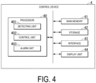
- FIG. 4 is a diagram illustrating a functional configuration of the control device according to the first embodiment of the present disclosure.
- the control device 4 includes a processor 40, a main memory 41, a storage 42, an interface 43, and a display unit 44.
- the processor 40 operates according to a predetermined program to function as a detecting unit 401, a control unit 402, and an alarm unit 403.
- the detecting unit 401 detects an anomaly in the water heat exchanger 23, based on a measurement value of each of the sensors provided in the refrigerant circuit 2 and the water circuit 3. Specifically, the detecting unit 401 detects a low-pressure anomaly in the water heat exchanger 23 when a saturation temperature of the refrigerant R is less than a predetermined saturation temperature lower limit value. The detecting unit 401 further detects presence or absence of a sign of leakage of the refrigerant R from the water heat exchanger 23 during each of the cooling operation, the heating operation, and the operation stop.
- control unit 402 performs various types of processing for suppressing entry of the water W into the refrigerant circuit 2.
- the alarm unit 403 issues an anomaly alarm via the display unit 44.
- the alarm unit 403 may issue an anomaly alarm to an external monitoring device (e.g., a computer, a smartphone, or a tablet) via the interface 43.
- an external monitoring device e.g., a computer, a smartphone, or a tablet
- Commands and data for the processor 40 to operate based on a program are deployed to the main memory 41.
- the storage 42 is a so-called auxiliary storage device, and may be, for example, an electrically erasable programmable read-only memory (EEPROM), a hard disk drive (HDD), or a solid state drive (SSD).
- EEPROM electrically erasable programmable read-only memory
- HDD hard disk drive
- SSD solid state drive
- the interface 43 is an interface (communication interface) for communicably connecting each device and sensor in the refrigerant circuit 2 and the water circuit 3.
- the display unit 44 is a display that displays information such as the presence or absence of an anomaly in the chilling unit 1.
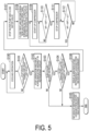
- FIG. 5 is a flowchart illustrating an example of processing of the control device according to the first embodiment of the present disclosure during the cooling operation.
- the control unit 402 controls the operating state of each device of the refrigerant circuit 2 and the water circuit 3 to perform the cooling operation of the chilling unit 1 (step S100). For example, as illustrated in FIG. 1 , the control unit 402 switches the four-way valve 22 such that the refrigerant R discharged by the compressor 21 flows into the air heat exchanger 26, and also brings the first expansion valve 241 into the open state and brings the second expansion valve 242 and the third expansion valve 243 into the closed state. Then, when the compressor 21 is operated, the four-way valve 22 switches to serve as a refrigerant circuit for the cooling operation.
- control unit 402 Before the control unit 402 operates the compressor 21, the control unit 402 operates the water pump 31 in the water circuit 3, and also brings the water valve 32 into the open state if the water valve 32 is installed. In this way, the water W flowing through the water circuit 3 is cooled by the refrigerant R while passing through the water heat exchanger 23.
- the detecting unit 401 constantly monitors a measurement value (pressure LP of the refrigerant R on the low-pressure side) of the low-pressure-side sensor 202 of the refrigerant circuit 2 during the cooling operation to detect presence or absence of a pressure anomaly of the refrigerant.
- a measurement value pressure LP of the refrigerant R on the low-pressure side
- the detecting unit 401 monitors whether a saturation temperature on the low-pressure side (hereinafter also described as an "LP saturation temperature”) is less than a first saturation temperature lower limit value (e.g., -A°C) (step S 101).
- a correspondence table of saturation pressure and saturation temperature for each type of the refrigerant R is previously recorded in the storage 42, and the detecting unit 401 determines the LP saturation temperature with reference to the correspondence table. Further, the first saturation temperature lower limit value is preset according to the type of the refrigerant R or the like.
- step S101: NO the detecting unit 401 determines that there is no anomaly in the pressure state of the refrigerant. In this case, the control device 4 continues the cooling operation of the chilling unit 1.
- the detecting unit 401 detects that an anomaly has occurred in low pressure of the refrigerant.
- the control unit 402 stops the cooling operation of the chilling unit 1.
- the alarm unit 403 issues an anomaly alarm indicating an anomaly in the refrigerant circuit 2 (step S102).
- the alarm unit 403 may display a value of the LP saturation temperature or the like together with the anomaly alarm on the display unit 44. Further, the alarm unit 403 may issue the anomaly alarm to an external monitoring terminal or the like via the interface 43.
- an administrator of the chilling unit 1 arranges for repair of the chilling unit 1.
- the detecting unit 401 confirms presence or absence of a sign of leakage of the refrigerant R into the water circuit 3 in the water heat exchanger 23. Specifically, first, the detecting unit 401 determines a subcooling degree at an outlet of the air heat exchanger 26, based on a measurement value of the first temperature sensor 203 immediately before the low-pressure anomaly occurs. Note that, in other embodiments, the first temperature sensor 203 may be a sensor that can measure a subcooling degree, and the detecting unit 401 may acquire the subcooling degree at the outlet of the air heat exchanger 26 from the first temperature sensor 203.
- the detecting unit 401 determines whether the subcooling degree at the outlet of the air heat exchanger 26 is significantly lower than a predetermined subcooling degree reference value, and whether subcooling cannot be guaranteed (step S 103).
- the subcooling degree reference value is preset according to the type of the refrigerant R or the like.
- step S 103 NO
- the detecting unit 401 determines that there is no sign of leakage of the refrigerant R (step S 105). In this case, the control unit 402 terminates the processing while the operation of the chilling unit 1 is stopped.
- the detecting unit 401 further confirms whether a water temperature at the outlet of the water heat exchanger 23 of the water circuit 3 immediately before the low-pressure anomaly occurs is less than a lower limit value (e.g., 3°C) in a water temperature control range (step S 104).
- the lower limit value in the water temperature control range indicates a set temperature in a settable temperature range in the chilling unit 1.
- the lower limit value is “4°C” when the set temperature is “4°C”
- the lower limit value is “7°C” when the set temperature is “7°C”.
- the detecting unit 401 determines that there is no sign of leakage of the refrigerant R (step S105).
- the low-pressure anomaly of the refrigerant is determined to be due to a cause other than refrigerant leakage from the water heat exchanger 23, for example, clogging of the refrigerant circuit 2.
- the control unit 402 terminates the processing while the operation of the chilling unit 1 is stopped.
- step S104 determines that leakage has already occurred in the water heat exchanger 23, and the refrigerant and water are mixed and the water temperature cannot be controlled.
- the alarm unit 403 issues an anomaly alarm indicating the refrigerant leakage in the water heat exchanger 23 (step S106).
- an administrator of the chilling unit 1 arranges for repair of the chilling unit 1.
- the refrigerant circuit 2 normally has a pressure higher than that of the water circuit 3.
- the water W of the water circuit 3 may enter the refrigerant circuit 2.
- it may take a long time from when repair is arranged to when repair of the chilling unit 1 is actually performed. Therefore, when the leakage of the refrigerant R is left until the repair of the chilling unit 1 is performed, the water W enters the refrigerant circuit 2, and damage to the chilling unit 1, such as failure of the compressor 21, may spread.
- control unit 402 performs automatic processing of suppressing entry of the water W into the refrigerant circuit 2 when the refrigerant leakage is detected. Details of this processing will be described with reference to FIGS. 5 and 6 .
- FIG. 6 is a diagram illustrating an example of a control state when refrigerant leakage in the chilling unit according to the first embodiment of the present disclosure is detected.
- the control unit 402 performs third processing of stopping the water pump 31 of the water circuit 3 and bringing the water valve 32 into the closed state (step S107). In this way, entry of the water W into the refrigerant circuit 2 can be suppressed. Further, in a system in which a plurality of the chilling units 1 are coupled with one water circuit 3, when the refrigerant R leaks into the water circuit 3 of a certain chilling unit 1, the water W mixed with the refrigerant R can be prevented from circulating in another chilling unit.
- the control unit 402 performs first processing (steps S108 and S109) of increasing pressure in the refrigerant circuit 2 such that the pressure in the refrigerant circuit 2 is not equalized with the pressure in the water circuit 3. Specifically, as illustrated in FIG. 6 , the control unit 402 brings the first expansion valve 241 and the second expansion valve 242 into the closed state, brings the third expansion valve 243 into the open state, and also operates the four-way valve 22 to switch to a heating operation flow path (step S108). Further, the control unit 402 starts up the compressor 21 (step S109).
- control unit 402 sends the refrigerant R compressed by the compressor 21 while limiting the flow path on a downstream side of the compressor 21 to a short section ending at the second expansion valve 242, and thus increases pressure in the section from the compressor 21 to the second expansion valve 242 in the refrigerant circuit 2, that is, a section around the water heat exchanger 23.
- control unit 402 performs second processing (steps S110 to S112) of maintaining the pressure in the section around the water heat exchanger 23 in the refrigerant circuit 2 within a fixed range.
- the control unit 402 confirms whether the high-pressure-side pressure HP of the refrigerant circuit 2 measured by the high-pressure-side sensor 201 after the compressor 21 starts up exceeds a pressure upper limit value (step S 110).
- the pressure upper limit value is, for example, a value acquired by adding a predetermined margin ⁇ 1 to the inlet-side pressure WP1 of the water circuit 3 measured by the first water pressure sensor 301.
- the value of the margin ⁇ 1 is preset according to the type of the refrigerant R, a characteristic of the compressor 21, or the like.
- step S110: NO the control unit 402 continues the operation of the compressor 21.
- step S110 the control unit 402 stops the compressor 21 (step S111). In this way, the control unit 402 can suppress an increase more than necessary in the pressure in the section around the water heat exchanger 23 of the refrigerant circuit 2 with respect to the pressure in the water circuit 3.
- the control unit 402 confirms whether the high-pressure-side pressure HP is less than the pressure lower limit value (step S112).
- the pressure upper limit value is, for example, a value acquired by adding a predetermined margin ⁇ 2 to the inlet-side pressure WP1 of the water circuit 3 measured by the first water pressure sensor 301.
- the value of the margin ⁇ 2 is preset according to the type of the refrigerant R, a characteristic of the compressor 21, or the like. Note that the values of the margins ⁇ 1 and ⁇ 2 may be the same, or may be different.
- step S112 NO
- the control unit 402 causes the compressor 21 to remain stopped.
- step S112 the control unit 402 starts up the compressor 21 (returns to step S109). In this way, the control unit 402 can suppress entry of the water W into the refrigerant circuit 2 because the pressure in the section around the water heat exchanger 23 of the refrigerant circuit 2 is equalized with the pressure in the water circuit 3.
- control unit 402 performs the first to third processing as illustrated in FIG. 5 , and suppresses entry of the water W in the water circuit 3 into the refrigerant circuit 2 to prevent the spread of damage in the chilling unit 1.
- FIG. 7 is a flowchart illustrating an example of processing of the control device according to the first embodiment of the present disclosure during the heating operation.
- the control unit 402 controls the operation state of each device of the refrigerant circuit 2 and the water circuit 3, and performs the heating operation of the chilling unit 1 (step S200). For example, as illustrated in FIG. 2 , the control unit 402 switches the four-way valve 22 such that the refrigerant R discharged by the compressor 21 flows into the water heat exchanger 23, and also brings the first expansion valve 241 into the closed state and brings the second expansion valve 242 and the third expansion valve 243 into the open state. When the control unit 402 switches the refrigerant circuit 2 to a heating operation flow path in such a manner, the control unit 402 operates the compressor 21.
- control unit 402 Before the control unit 402 operates the compressor 21, the control unit 402 operates the water pump 31 in the water circuit 3, and also brings the water valve 32 into the open state if the water valve 32 is installed. In this way, the water W flowing through the water circuit 3 is heated by the refrigerant R while passing through the water heat exchanger 23.
- the detecting unit 401 constantly monitors the pressure LP of the refrigerant R on the low-pressure side during the heating operation to detect presence or absence of an anomaly in the water heat exchanger 23. Specifically, the detecting unit 401 monitors whether an outside temperature is equal to or greater than 0°C and whether the LP saturation temperature is less than a second saturation temperature lower limit value (e.g., -B°C) (step S201).
- a second saturation temperature lower limit value is preset according to the type of the refrigerant R or the like.
- step S201: NO the detecting unit 401 determines that there is no anomaly (no leakage) in the refrigerant circuit 2. In this case, the control device 4 continues the heating operation of the chilling unit 1.
- the detecting unit 401 detects that leakage from the refrigerant circuit 2 may occur and there may be a sign of leakage of the refrigerant R in the water heat exchanger 23.
- the control unit 402 stops the heating operation of the chilling unit 1.
- the alarm unit 403 issues an anomaly alarm indicating the sign of refrigerant leakage in the water heat exchanger 23 (step S202).
- control unit 402 When the sign of refrigerant leakage is detected, the control unit 402 performs processing of suppressing entry of the water W into the refrigerant circuit 2 similarly to the cooling operation.
- control unit 402 performs third processing of stopping the water pump 31 of the water circuit 3 and bringing the water valve 32 into the closed state (step S203). This processing is the same as that in step S107 in FIG. 5 .
- the control unit 402 performs first processing (steps S204 and S205) of increasing pressure in the refrigerant circuit 2 such that the pressure in the refrigerant circuit 2 is not equalized with pressure in the water circuit 3.
- the flow path may switch to the flow path during the operation stop illustrated in FIG. 3 .
- the control unit 402 brings the first expansion valve 241 and the second expansion valve 242 into the closed state, brings the third expansion valve 243 into the open state, and also operates the four-way valve 22 to switch to the heating operation flow path (step S204).
- control unit 402 starts up the compressor 21 (step S205), and increases pressure in the section from the compressor 21 to the second expansion valve 242 in the refrigerant circuit 2, that is, the section around the water heat exchanger 23.
- This processing is the same as that in steps S108 to S109 in FIG. 5 .
- control unit 402 performs second processing (steps S206 to S208) of maintaining the pressure in the section around the water heat exchanger 23 of the refrigerant circuit 2 within a fixed range. This processing is the same as that in steps S110 to S112 in FIG. 5 .
- control unit 402 When a sign of leakage of the refrigerant R is detected during the heating operation, the control unit 402 performs the first to third processing as illustrated in FIG. 7 , and suppresses a decrease in the pressure in the refrigerant circuit 2 and entry of the water W in the water circuit 3 into the refrigerant circuit 2.
- FIG. 8 is a flowchart illustrating an example of processing of the control device according to the first embodiment of the present disclosure during the operation stop.
- the control unit 402 brings the chilling unit 1 into a state of operation stop according to an operation by an administrator or the like of the chilling unit 1 (step S300). At this time, as illustrated in FIG. 3 , the control unit 402 brings the first expansion valve 241 and the third expansion valve 243 into the closed state and brings the second expansion valve 242 into the open state to stop the compressor 21. Further, the control unit 402 stops the water pump 31 and brings the water valve 32 into the closed state. Note that, in other embodiments, for protection control, the control unit 402 may operate the water pump 31 and bring the water valve 32 into the open state even during the operation stop.
- the detecting unit 401 constantly monitors the low-pressure-side pressure LP or the high-pressure-side pressure HP of the refrigerant R during the operation stop to detect presence or absence of an anomaly in the water heat exchanger 23. Specifically, the detecting unit 401 monitors whether an outside temperature is equal to or greater than 0°C and whether the LP saturation temperature or a saturation temperature on the high-pressure side (hereinafter also described as an "HP saturation temperature") is less than a third saturation temperature lower limit value (e.g., -C°C) (step S301).
- the third saturation temperature lower limit value is preset according to the type of the refrigerant R or the like.
- the detecting unit 401 determines that there is no problem in the refrigerant circuit 2 and there is no anomaly in the water heat exchanger 23. In this case, the control device 4 causes the chilling unit 1 to remain in the state of the operation stop.
- the detecting unit 401 detects that leakage from the refrigerant circuit 2 may occur and there may be a sign of leakage of the refrigerant R in the water heat exchanger 23. In this case, the alarm unit 403 issues an anomaly alarm indicating a sign of the refrigerant leakage from the refrigerant circuit 2 (step S302).
- control unit 402 When the sign of refrigerant leakage is detected, the control unit 402 performs processing of suppressing entry of the water W into the refrigerant circuit 2 similarly to the cooling operation.
- step S303 In a case of operation of operating the water pump 31 even during the operation stop, the control unit 402 performs third processing of stopping the water pump 31 of the water circuit 3, and also bringing the water valve 32 into the closed state (step S303). This processing is the same as that in step S107 in FIG. 5 . Note that, in a case of an operation of stopping the water pump 31 during the operation stop, step S303 may be omitted.
- the control unit 402 performs first processing (steps S304 and S305) of increasing pressure in the refrigerant circuit 2 such that the pressure in the refrigerant circuit 2 is not equalized with pressure in the water circuit 3. This processing is the same as that in steps S108 to S109 in FIG. 5 .
- control unit 402 performs second processing (steps S306 to S308) of maintaining the pressure in the section around the water heat exchanger 23 of the refrigerant circuit 2 within a fixed range. This processing is the same as that in steps S110 to S112 in FIG. 5 .
- control unit 402 When a sign of leakage of the refrigerant R is detected during the operation stop, the control unit 402 performs the first to third processing as illustrated in FIG. 8 , and suppresses a decrease in the pressure in the refrigerant circuit 2 and entry of the water W in the water circuit 3 into the refrigerant circuit 2.
- step S301 in FIG. 8 when the outside temperature is equal to or greater than 0°C, and the LP saturation temperature or the HP saturation temperature is less than the third saturation temperature lower limit value (when a first condition is satisfied), the detecting unit 401 according to the present embodiment detects that a sign of leakage of the refrigerant R has occurred, and, in steps S303 to S308, the detecting unit 401 assumes leakage from the water heat exchanger 23 and performs maintenance control, which is not limited thereto.
- the detecting unit 401 may detect that a sign of leakage of the refrigerant R has occurred in the water heat exchanger 23.
- a case in which the second condition is satisfied is, for example, a case in which the outside temperature is equal to or greater than 0°C and a difference between the LP saturation temperature (or the HP saturation temperature) and the outside temperature is equal to or greater than a predetermined temperature differential (e.g., 10 degrees), and a change in the LP saturation temperature (or the HP saturation temperature) does not follow a temperature change of the outside temperature.
- the detecting unit 401 can detect the refrigerant leakage of the refrigerant R by confirming whether the second condition is satisfied.
- FIGS. 5 , 7 , and 8 illustrate an example in which the control unit 402 performs the first processing (steps S108 and S109, S204 and S205, and S304 and S305) after the third processing (steps S 107, S203, and S303), but the order of the processing is not limited thereto.
- the control unit 402 may perform the third processing after the first processing or simultaneously with the first processing.
- the control device 4 includes the detecting unit 401 configured to detect an anomaly in the water heat exchanger 23 when an LP saturation temperature or an HP saturation temperature of the refrigerant circuit 2 is less than a predetermined saturation temperature lower limit value.
- the chilling unit 1 can quickly detect an anomaly in the water heat exchanger 23.
- the detecting unit 401 of the control device 4 detects an anomaly indicating refrigerant leakage in the water heat exchanger 23 when, during a cooling operation, the LP saturation temperature of the refrigerant circuit 2 is less than a first saturation temperature lower limit value, a subcooling degree at an outlet of the air heat exchanger 26 is lower than a subcooling degree reference value, and a water temperature at an outlet of the water heat exchanger 23 of the water circuit 3 is equal to or greater than a lower limit value in a water temperature control range.
- the chilling unit 1 can quickly detect refrigerant leakage during the cooling operation.
- the detecting unit 401 of the control device 4 detects an anomaly indicating a sign of refrigerant leakage in the water heat exchanger 23 when the LP saturation temperature of the refrigerant circuit 2 is less than a second saturation temperature lower limit value during a heating operation.
- the chilling unit 1 can quickly detect a sign of refrigerant leakage during the heating operation.
- the detecting unit 401 of the control device 4 detects an anomaly indicating a sign of refrigerant leakage in the water heat exchanger 23 when the LP saturation temperature or the HP saturation temperature of the refrigerant circuit 2 is less than a third saturation temperature lower limit value during an operation stop.
- the chilling unit 1 can quickly detect a sign of refrigerant leakage during the operation stop.
- control device 4 further includes the control unit 402 that performs first processing of closing the first expansion valve 241 and the second expansion valve 242, switching the four-way valve 22 so as to set the heating operation flow path, and starting up the compressor 21 when a sign of the refrigerant leakage is detected.
- the chilling unit 1 can maintain a state where the refrigerant circuit 2 has pressure greater than that of the water circuit 3, and can suppress entry of the water W into the refrigerant circuit 2. In this way, the likelihood of each device connected to the refrigerant circuit 2 being damaged by the water that enters the refrigerant circuit 2 can be reduced.
- control unit 402 of the control device 4 further performs second processing of, after the first processing is performed, stopping the compressor 21 when the high-pressure-side pressure HP of the refrigerant circuit 2 is equal to or greater than a pressure upper limit value, and starting up the compressor 21 when the high-pressure-side pressure HP of the refrigerant circuit 2 is less than a pressure lower limit value.
- the chilling unit 1 can maintain pressure in the section around the water heat exchanger 23 of the refrigerant circuit 2 within a fixed range. In this way, entry of the water W from the water circuit 3 into the refrigerant circuit 2 can be suppressed.
- control unit 402 of the control device 4 sets, as the pressure lower limit value, a value acquired by adding the predetermined margin ⁇ 2 to the inlet-side pressure WP1 of the water circuit 3.
- the chilling unit 1 can maintain pressure in the section around the water heat exchanger 23 of the refrigerant circuit 2 in a state of being higher than pressure in the water circuit 3. In this way, entry of the water W from the water circuit 3 into the refrigerant circuit 2 can be more reliably suppressed.
- control unit 402 of the control device 4 further performs third processing of stopping the water pump 31 and closing the water valve 32 when a sign of the refrigerant leakage is detected.
- the chilling unit, the control method, and the program described in the embodiment above are understood as follows, for example.
Landscapes
- Engineering & Computer Science (AREA)
- Physics & Mathematics (AREA)
- Mechanical Engineering (AREA)
- Thermal Sciences (AREA)
- General Engineering & Computer Science (AREA)
- Air Conditioning Control Device (AREA)
- Compression-Type Refrigeration Machines With Reversible Cycles (AREA)
Abstract
Description
- The present disclosure relates to a chilling unit, a control method, and a program.
- In a chilling unit, when a heat exchanger (hereinafter also described as a "water heat exchanger") configured to exchange heat between a refrigerant and water is damaged due to, for example, freezing or corrosion due to water quality, the refrigerant may leak from the refrigerant circuit to the water circuit. Patent Document 1 describes a technology of detecting refrigerant leakage when concentration of the refrigerant exceeds a reference value for a certain period of time or longer.
- Patent Document 1:
JP 2020-51738 A - If the chilling unit continues to operate in a state where the water heat exchanger is damaged, pressure in the refrigerant circuit and pressure in the water circuit may become equalized. In this case, water may enter the refrigerant circuit. When water enters the refrigerant circuit, each device connected to the refrigerant circuit, including a compressor, an accumulator, a receiver, and valves (e.g., an expansion valve and a four-way valve), in addition to the water heat exchanger, may need to be replaced during repair, and it may cost to repair and take days until restoration. Therefore, an anomaly such as damage to the water heat exchanger is preferably quickly detected such that the damage does not spread.
- The present disclosure has been made in view of such a problem, and provides a chilling unit, a control method, and a program that can quickly detect an anomaly in a water heat exchanger.
- According to one aspect of the present disclosure, a chilling unit includes: a refrigerant circuit including a compressor that is configured to compress a refrigerant, an air heat exchanger that is configured to perform heat exchange between the refrigerant and outside air, a water heat exchanger that is configured to perform heat exchange between the refrigerant and water, an expansion valve provided between the air heat exchanger and the water heat exchanger, and a four-way valve that is configured to switch a flow path of the refrigerant to a cooling operation flow path or a heating operation flow path; a water circuit including a water pipe inserted through the water heat exchanger, a water pump that is configured to send the water to the water pipe, and a water valve provided closer to a downstream side of the water pipe than the water heat exchanger; and a control device configured to control the refrigerant circuit and the water circuit, wherein the control device includes a detecting unit configured to detect an anomaly in the water heat exchanger when a saturation temperature of the refrigerant circuit on a low-pressure side or a high-pressure side is less than a predetermined saturation temperature lower limit value.
- According to one aspect of the present disclosure, a control method is a method for controlling a chilling unit including a refrigerant circuit including a compressor that is configured to compress a refrigerant, an air heat exchanger that is configured to perform heat exchange between the refrigerant and outside air, a water heat exchanger that is configured to perform heat exchange between the refrigerant and water, an expansion valve provided between the air heat exchanger and the water heat exchanger, and a four-way valve that is configured to switch a flow path of the refrigerant to a cooling operation flow path or a heating operation flow path, a water circuit including a water pipe inserted through the water heat exchanger, a water pump that is configured to send the water to the water pipe, and a water valve provided closer to a downstream side of the water pipe than the water heat exchanger, and a control device configured to control the refrigerant circuit and the water circuit, in which the control method includes detecting, by the control device, an anomaly in the water heat exchanger when a saturation temperature of the refrigerant circuit on a low-pressure side or a high-pressure side is less than a predetermined saturation temperature lower limit value.
- According to one aspect of the present disclosure, a program causes a control device of a chilling unit including a refrigerant circuit including a compressor that is configured to compress a refrigerant, an air heat exchanger that is configured to perform heat exchange between the refrigerant and outside air, a water heat exchanger that is configured to perform heat exchange between the refrigerant and water, an expansion valve provided between the air heat exchanger and the water heat exchanger, and a four-way valve that is configured to switch a flow path of the refrigerant to a cooling operation flow path or a heating operation flow path, and a water circuit including a water pipe inserted through the water heat exchanger, a water pump that is configured to send the water to the water pipe, and a water valve provided closer to a downstream side of the water pipe than the water heat exchanger, to execute detecting an anomaly in the water heat exchanger when a saturation temperature of the refrigerant circuit on a low-pressure side or a high-pressure side is less than a predetermined saturation temperature lower limit value.
- A chilling unit, a control method, and a program according to the present disclosure can quickly detect an anomaly in a water heat exchanger.
-
-
FIG. 1 is a first diagram illustrating a configuration of a chilling unit according to a first embodiment of the present disclosure, and is a diagram illustrating an example of a control state during a cooling operation. -
FIG. 2 is a second diagram illustrating the configuration of the chilling unit according to the first embodiment of the present disclosure, and is a diagram illustrating an example of a control state during a heating operation. -
FIG. 3 is a third diagram illustrating the configuration of the chilling unit according to the first embodiment of the present disclosure, and is a diagram illustrating an example of a control state during an operation stop. -
FIG. 4 is a diagram illustrating a functional configuration of a control device according to the first embodiment of the present disclosure. -
FIG. 5 is a flowchart illustrating an example of processing of the control device according to the first embodiment of the present disclosure during the cooling operation. -
FIG. 6 is a diagram illustrating an example of a control state when refrigerant leakage in the chilling unit according to the first embodiment of the present disclosure is detected. -
FIG. 7 is a flowchart illustrating an example of processing of the control device according to the first embodiment of the present disclosure during the heating operation. -
FIG. 8 is a flowchart illustrating an example of processing of the control device according to the first embodiment of the present disclosure during the operation stop. - Hereinafter, a chilling unit according to a first embodiment of the present disclosure will be described with reference to
FIGS. 1 to 8 . -
FIG. 1 is a first diagram illustrating a configuration of the chilling unit according to the first embodiment of the present disclosure, and is a diagram illustrating an example of a control state during a cooling operation. -
FIG. 2 is a second diagram illustrating the configuration of the chilling unit according to the first embodiment of the present disclosure, and is a diagram illustrating an example of a control state during a heating operation. -
FIG. 3 is a third diagram illustrating the configuration of the chilling unit according to the first embodiment of the present disclosure, and is a diagram illustrating an example of a control state during an operation stop. - As illustrated in
FIGS. 1 to 3 , a chilling unit 1 includes arefrigerant circuit 2, awater circuit 3, and acontrol device 4. - The
refrigerant circuit 2 includes acompressor 21, a four-way valve 22, awater heat exchanger 23, anexpansion valve 24, areceiver 25, anair heat exchanger 26, and anaccumulator 27. Each device of therefrigerant circuit 2 is connected by arefrigerant pipe 20. - The
compressor 21 compresses a refrigerant R and supplies the compressed refrigerant R to therefrigerant circuit 2. - The four-
way valve 22 switches between the cooling operation and the heating operation by switching the flow path of therefrigerant circuit 2. As illustrated inFIG. 1 , the four-way valve 22 feeds, to theair heat exchanger 26, the refrigerant R discharged from thecompressor 21 during the cooling operation. Further, as illustrated inFIG. 2 , the four-way valve 22 feeds, to thewater heat exchanger 23, the refrigerant R discharged from thecompressor 21 during the heating operation. - The water heat exchanger 23 cools or heats water W by performing heat exchange between the refrigerant R and the water W.
- The
expansion valve 24 includes a mechanism for reducing pressure of the refrigerant R when the refrigerant R passes through theexpansion valve 24. As illustrated inFIG. 1 , theexpansion valve 24 includes afirst expansion valve 241, asecond expansion valve 242, and athird expansion valve 243. Thefirst expansion valve 241 is an expansion valve for the cooling operation. Thesecond expansion valve 242 and thethird expansion valve 243 are expansion valves for the heating operation. Thesecond expansion valve 242 is provided between thewater heat exchanger 23 and thereceiver 25, and thethird expansion valve 243 is provided between thereceiver 25 and theair heat exchanger 26. - As illustrated in
FIG. 1 , during the cooling operation, thefirst expansion valve 241 is in an open state, and thesecond expansion valve 242 and thethird expansion valve 243 are in a closed state. As illustrated inFIG. 2 , during the heating operation, thefirst expansion valve 241 is in the closed state, and thesecond expansion valve 242 and thethird expansion valve 243 are in the open state. Further, as illustrated inFIG. 3 , during an operation stop, thefirst expansion valve 241 and thethird expansion valve 243 are in a closed state, and thesecond expansion valve 242 is in an open state. - The
receiver 25 is a container for storing at least some of a liquid refrigerant that passes through thesecond expansion valve 242 or thethird expansion valve 243. - The
air heat exchanger 26 performs heat exchange between the refrigerant R and outside air taken in by apropeller fan 261. - The
accumulator 27 is a device that is provided on an upstream side of thecompressor 21 and separates liquid refrigerant and gas refrigerant. Only the gas refrigerant of the refrigerant separated by theaccumulator 27 is sent to thecompressor 21. - A plurality of sensors for measuring the pressure and temperature of the refrigerant R are provided in the
refrigerant circuit 2. A high-pressure-side sensor 201 that measures pressure (HP) of the refrigerant R on a high-pressure side is provided in therefrigerant pipe 20 between thecompressor 21 and the four-way valve 22 (on a downstream side of the compressor 21). A low-pressure-side sensor 202 that measures pressure (LP) of the refrigerant R on a low-pressure side is provided in therefrigerant pipe 20 between theaccumulator 27 and the four-way valve 22 (on an upstream side of the accumulator 27). Further, afirst temperature sensor 203 that measures a temperature of the refrigerant R is provided in therefrigerant pipe 20 between theexpansion valve 24 and theair heat exchanger 26. Measurement values measured by each of the sensors are sequentially transmitted to thecontrol device 4. - The
water circuit 3 includes awater pipe 30, awater pump 31, and awater valve 32. Thewater pipe 30 is inserted through thewater heat exchanger 23. Thewater pump 31 is provided closer to an upstream side of thewater pipe 30 than thewater heat exchanger 23, and sends the water W from the outside to thewater pipe 30. While passing through thewater heat exchanger 23, the water W sent by thewater pump 31 undergoes heat exchange with the refrigerant R so that the temperature of the water W is adjusted. Thewater valve 32 is provided closer to a downstream side of thewater pipe 30 than thewater heat exchanger 23. When thewater valve 32 is opened, the water W after undergoing temperature adjustment is discharged to the outside through thewater pipe 30. When thewater valve 32 is closed, the discharge of the water W to the outside is stopped. - A plurality of sensors for measuring the pressure and temperature of the water W are provided in the
water circuit 3. A firstwater pressure sensor 301 that measures pressure (WP1) of the water W on an inlet side of thewater heat exchanger 23 is provided in thewater pipe 30 on an upstream side of thewater heat exchanger 23. A secondwater pressure sensor 302 that measures pressure (WP2) of the water W on an outlet side of thewater heat exchanger 23 is provided in thewater pipe 30 on a downstream side of thewater heat exchanger 23. Further, asecond temperature sensor 303 that measures a temperature of the water W is provided in thewater pipe 30 on the downstream side (near the outlet) of thewater heat exchanger 23. Measurement values measured by each of the sensors are sequentially transmitted to thecontrol device 4. - The
control device 4 controls the operation of each device of therefrigerant circuit 2 and thewater circuit 3, and brings the chilling unit 1 into any state of the cooling operation, the heating operation, and the operation stop. - The
control device 4 according to the present embodiment detects an anomaly in thewater heat exchanger 23 on the basis of a measurement value received from each of the sensors of therefrigerant circuit 2 and thewater circuit 3. Further, thecontrol device 4 performs processing of suppressing entry of the water W into therefrigerant circuit 2 when a sign of leakage of the refrigerant R is detected in thewater heat exchanger 23. The details of this processing will be described later. -
FIG. 4 is a diagram illustrating a functional configuration of the control device according to the first embodiment of the present disclosure. - As illustrated in
FIG. 4 , thecontrol device 4 includes aprocessor 40, amain memory 41, astorage 42, aninterface 43, and adisplay unit 44. - The
processor 40 operates according to a predetermined program to function as a detectingunit 401, acontrol unit 402, and analarm unit 403. - The detecting
unit 401 detects an anomaly in thewater heat exchanger 23, based on a measurement value of each of the sensors provided in therefrigerant circuit 2 and thewater circuit 3. Specifically, the detectingunit 401 detects a low-pressure anomaly in thewater heat exchanger 23 when a saturation temperature of the refrigerant R is less than a predetermined saturation temperature lower limit value. The detectingunit 401 further detects presence or absence of a sign of leakage of the refrigerant R from thewater heat exchanger 23 during each of the cooling operation, the heating operation, and the operation stop. - In a case where a sign of leakage of the refrigerant R from the
water heat exchanger 23 is detected, thecontrol unit 402 performs various types of processing for suppressing entry of the water W into therefrigerant circuit 2. - In a case where an anomaly in the
water heat exchanger 23 is detected, thealarm unit 403 issues an anomaly alarm via thedisplay unit 44. Note that thealarm unit 403 may issue an anomaly alarm to an external monitoring device (e.g., a computer, a smartphone, or a tablet) via theinterface 43. - Commands and data for the
processor 40 to operate based on a program are deployed to themain memory 41. - The
storage 42 is a so-called auxiliary storage device, and may be, for example, an electrically erasable programmable read-only memory (EEPROM), a hard disk drive (HDD), or a solid state drive (SSD). - The
interface 43 is an interface (communication interface) for communicably connecting each device and sensor in therefrigerant circuit 2 and thewater circuit 3. - The
display unit 44 is a display that displays information such as the presence or absence of an anomaly in the chilling unit 1. -
FIG. 5 is a flowchart illustrating an example of processing of the control device according to the first embodiment of the present disclosure during the cooling operation. - Hereinafter, a flow of processing of monitoring an anomaly in the
water heat exchanger 23 during a cooling operation and processing at the time of an anomaly will be described with reference toFIG. 5 . - The
control unit 402 controls the operating state of each device of therefrigerant circuit 2 and thewater circuit 3 to perform the cooling operation of the chilling unit 1 (step S100). For example, as illustrated inFIG. 1 , thecontrol unit 402 switches the four-way valve 22 such that the refrigerant R discharged by thecompressor 21 flows into theair heat exchanger 26, and also brings thefirst expansion valve 241 into the open state and brings thesecond expansion valve 242 and thethird expansion valve 243 into the closed state. Then, when thecompressor 21 is operated, the four-way valve 22 switches to serve as a refrigerant circuit for the cooling operation. Before thecontrol unit 402 operates thecompressor 21, thecontrol unit 402 operates thewater pump 31 in thewater circuit 3, and also brings thewater valve 32 into the open state if thewater valve 32 is installed. In this way, the water W flowing through thewater circuit 3 is cooled by the refrigerant R while passing through thewater heat exchanger 23. - Further, the detecting
unit 401 constantly monitors a measurement value (pressure LP of the refrigerant R on the low-pressure side) of the low-pressure-side sensor 202 of therefrigerant circuit 2 during the cooling operation to detect presence or absence of a pressure anomaly of the refrigerant. In the present embodiment, each time the detectingunit 401 receives a measurement value from the low-pressure-side sensor 202, the detectingunit 401 monitors whether a saturation temperature on the low-pressure side (hereinafter also described as an "LP saturation temperature") is less than a first saturation temperature lower limit value (e.g., -A°C) (step S 101). For example, a correspondence table of saturation pressure and saturation temperature for each type of the refrigerant R is previously recorded in thestorage 42, and the detectingunit 401 determines the LP saturation temperature with reference to the correspondence table. Further, the first saturation temperature lower limit value is preset according to the type of the refrigerant R or the like. - In a case where the LP saturation temperature is equal to or greater than the first saturation temperature lower limit value (step S101: NO), the detecting
unit 401 determines that there is no anomaly in the pressure state of the refrigerant. In this case, thecontrol device 4 continues the cooling operation of the chilling unit 1. - On the other hand, in a case where the LP saturation temperature is less than the first saturation temperature lower limit value (step S101: YES), the detecting
unit 401 detects that an anomaly has occurred in low pressure of the refrigerant. In this case, thecontrol unit 402 stops the cooling operation of the chilling unit 1. Further, thealarm unit 403 issues an anomaly alarm indicating an anomaly in the refrigerant circuit 2 (step S102). At this time, thealarm unit 403 may display a value of the LP saturation temperature or the like together with the anomaly alarm on thedisplay unit 44. Further, thealarm unit 403 may issue the anomaly alarm to an external monitoring terminal or the like via theinterface 43. When the low-pressure anomaly alarm for the refrigerant is issued, an administrator of the chilling unit 1 arranges for repair of the chilling unit 1. - Next, the detecting
unit 401 confirms presence or absence of a sign of leakage of the refrigerant R into thewater circuit 3 in thewater heat exchanger 23. Specifically, first, the detectingunit 401 determines a subcooling degree at an outlet of theair heat exchanger 26, based on a measurement value of thefirst temperature sensor 203 immediately before the low-pressure anomaly occurs. Note that, in other embodiments, thefirst temperature sensor 203 may be a sensor that can measure a subcooling degree, and the detectingunit 401 may acquire the subcooling degree at the outlet of theair heat exchanger 26 from thefirst temperature sensor 203. Then, the detectingunit 401 determines whether the subcooling degree at the outlet of theair heat exchanger 26 is significantly lower than a predetermined subcooling degree reference value, and whether subcooling cannot be guaranteed (step S 103). Note that the subcooling degree reference value is preset according to the type of the refrigerant R or the like. - In a case where the subcooling degree at the outlet of the
air heat exchanger 26 is not lower than the subcooling degree reference value (step S 103: NO), the detectingunit 401 determines that there is no sign of leakage of the refrigerant R (step S 105). In this case, thecontrol unit 402 terminates the processing while the operation of the chilling unit 1 is stopped. - On the other hand, in a case where the subcooling degree at the outlet of the
air heat exchanger 26 is lower than the subcooling degree reference value (step S 103: YES), the detectingunit 401 further confirms whether a water temperature at the outlet of thewater heat exchanger 23 of thewater circuit 3 immediately before the low-pressure anomaly occurs is less than a lower limit value (e.g., 3°C) in a water temperature control range (step S 104). The lower limit value in the water temperature control range indicates a set temperature in a settable temperature range in the chilling unit 1. For example, in a case where the settable temperature range is "from 4°C to 30°C", the lower limit value is "4°C" when the set temperature is "4°C", and the lower limit value is "7°C" when the set temperature is "7°C". - When there is no refrigerant leakage at the time of a low-temperature anomaly (the amount of the refrigerant R is sufficient in the refrigerant circuit 2), the water temperature decreases (reaches a subcooling temperature) as the pressure LP on the low-pressure side decreases. Thus, in a case where the water temperature at the outlet of the
water heat exchanger 23 measured by thesecond temperature sensor 303 is less than the lower limit value in the water temperature control range (step S104: NO), the detectingunit 401 determines that there is no sign of leakage of the refrigerant R (step S105). In other words, the low-pressure anomaly of the refrigerant is determined to be due to a cause other than refrigerant leakage from thewater heat exchanger 23, for example, clogging of therefrigerant circuit 2. In this case, thecontrol unit 402 terminates the processing while the operation of the chilling unit 1 is stopped. - On the other hand, in a case where there is refrigerant leakage at the time of the low-pressure anomaly, the amount of the refrigerant R is insufficient, and thus it is difficult to sufficiently perform cooling until the lower limit value (set temperature) is reached. Thus, in a case where the water temperature at the outlet of the
water heat exchanger 23 is equal to or greater than the lower limit value in the water temperature control range (step S104: YES), the detectingunit 401 determines that leakage has already occurred in thewater heat exchanger 23, and the refrigerant and water are mixed and the water temperature cannot be controlled. In this case, thealarm unit 403 issues an anomaly alarm indicating the refrigerant leakage in the water heat exchanger 23 (step S106). When the anomaly alarm indicating the refrigerant leakage from thewater heat exchanger 23 is issued, an administrator of the chilling unit 1 arranges for repair of the chilling unit 1. - The
refrigerant circuit 2 normally has a pressure higher than that of thewater circuit 3. However, when leakage of the refrigerant R advances and pressure in therefrigerant circuit 2 and pressure in thewater circuit 3 are equalized, the water W of thewater circuit 3 may enter therefrigerant circuit 2. In addition, it may take a long time from when repair is arranged to when repair of the chilling unit 1 is actually performed. Therefore, when the leakage of the refrigerant R is left until the repair of the chilling unit 1 is performed, the water W enters therefrigerant circuit 2, and damage to the chilling unit 1, such as failure of thecompressor 21, may spread. - In order to reduce the likelihood of such damage to the chilling unit 1 spreading, the
control unit 402 according to the present embodiment performs automatic processing of suppressing entry of the water W into therefrigerant circuit 2 when the refrigerant leakage is detected. Details of this processing will be described with reference toFIGS. 5 and6 . -
FIG. 6 is a diagram illustrating an example of a control state when refrigerant leakage in the chilling unit according to the first embodiment of the present disclosure is detected. - First, processing in the
water circuit 3 will be described. In a case where thewater heat exchanger 23 is damaged, when the water W flows on thewater circuit 3 side, the water W may leak into therefrigerant circuit 2. Thus, as illustrated inFIG. 6 , thecontrol unit 402 performs third processing of stopping thewater pump 31 of thewater circuit 3 and bringing thewater valve 32 into the closed state (step S107). In this way, entry of the water W into therefrigerant circuit 2 can be suppressed. Further, in a system in which a plurality of the chilling units 1 are coupled with onewater circuit 3, when the refrigerant R leaks into thewater circuit 3 of a certain chilling unit 1, the water W mixed with the refrigerant R can be prevented from circulating in another chilling unit. - Further, processing in the
refrigerant circuit 2 will be described. Thecontrol unit 402 performs first processing (steps S108 and S109) of increasing pressure in therefrigerant circuit 2 such that the pressure in therefrigerant circuit 2 is not equalized with the pressure in thewater circuit 3. Specifically, as illustrated inFIG. 6 , thecontrol unit 402 brings thefirst expansion valve 241 and thesecond expansion valve 242 into the closed state, brings thethird expansion valve 243 into the open state, and also operates the four-way valve 22 to switch to a heating operation flow path (step S108). Further, thecontrol unit 402 starts up the compressor 21 (step S109). In this way, thecontrol unit 402 sends the refrigerant R compressed by thecompressor 21 while limiting the flow path on a downstream side of thecompressor 21 to a short section ending at thesecond expansion valve 242, and thus increases pressure in the section from thecompressor 21 to thesecond expansion valve 242 in therefrigerant circuit 2, that is, a section around thewater heat exchanger 23. - Furthermore, the
control unit 402 performs second processing (steps S110 to S112) of maintaining the pressure in the section around thewater heat exchanger 23 in therefrigerant circuit 2 within a fixed range. - First, the
control unit 402 confirms whether the high-pressure-side pressure HP of therefrigerant circuit 2 measured by the high-pressure-side sensor 201 after thecompressor 21 starts up exceeds a pressure upper limit value (step S 110). The pressure upper limit value is, for example, a value acquired by adding a predetermined margin α1 to the inlet-side pressure WP1 of thewater circuit 3 measured by the firstwater pressure sensor 301. The value of the margin α1 is preset according to the type of the refrigerant R, a characteristic of thecompressor 21, or the like. - In a case where the high-pressure-side pressure HP is equal to or less than the pressure upper limit value (step S110: NO), the
control unit 402 continues the operation of thecompressor 21. - On the other hand, in a case where the high-pressure-side pressure HP exceeds the pressure upper limit value (step S110: YES), the
control unit 402 stops the compressor 21 (step S111). In this way, thecontrol unit 402 can suppress an increase more than necessary in the pressure in the section around thewater heat exchanger 23 of therefrigerant circuit 2 with respect to the pressure in thewater circuit 3. - Further, after the
control unit 402 stops thecompressor 21, thecontrol unit 402 confirms whether the high-pressure-side pressure HP is less than the pressure lower limit value (step S112). The pressure upper limit value is, for example, a value acquired by adding a predetermined margin α2 to the inlet-side pressure WP1 of thewater circuit 3 measured by the firstwater pressure sensor 301. The value of the margin α2 is preset according to the type of the refrigerant R, a characteristic of thecompressor 21, or the like. Note that the values of the margins α1 and α2 may be the same, or may be different. - In a case where the high-pressure-side pressure HP is equal to or greater than the pressure lower limit value (step S112: NO), the
control unit 402 causes thecompressor 21 to remain stopped. - On the other hand, in a case where the high-pressure-side pressure HP is less than the pressure lower limit value (step S112: YES), the
control unit 402 starts up the compressor 21 (returns to step S109). In this way, thecontrol unit 402 can suppress entry of the water W into therefrigerant circuit 2 because the pressure in the section around thewater heat exchanger 23 of therefrigerant circuit 2 is equalized with the pressure in thewater circuit 3. - In this way, when a sign of leakage of the refrigerant R is detected during the cooling operation, the
control unit 402 performs the first to third processing as illustrated inFIG. 5 , and suppresses entry of the water W in thewater circuit 3 into therefrigerant circuit 2 to prevent the spread of damage in the chilling unit 1. -
FIG. 7 is a flowchart illustrating an example of processing of the control device according to the first embodiment of the present disclosure during the heating operation. - Hereinafter, a flow of processing of monitoring an anomaly in the
water heat exchanger 23 during the heating operation and processing at the time of the anomaly will be described with reference toFIG. 7 . - The
control unit 402 controls the operation state of each device of therefrigerant circuit 2 and thewater circuit 3, and performs the heating operation of the chilling unit 1 (step S200). For example, as illustrated inFIG. 2 , thecontrol unit 402 switches the four-way valve 22 such that the refrigerant R discharged by thecompressor 21 flows into thewater heat exchanger 23, and also brings thefirst expansion valve 241 into the closed state and brings thesecond expansion valve 242 and thethird expansion valve 243 into the open state. When thecontrol unit 402 switches therefrigerant circuit 2 to a heating operation flow path in such a manner, thecontrol unit 402 operates thecompressor 21. Before thecontrol unit 402 operates thecompressor 21, thecontrol unit 402 operates thewater pump 31 in thewater circuit 3, and also brings thewater valve 32 into the open state if thewater valve 32 is installed. In this way, the water W flowing through thewater circuit 3 is heated by the refrigerant R while passing through thewater heat exchanger 23. - Further, the detecting
unit 401 constantly monitors the pressure LP of the refrigerant R on the low-pressure side during the heating operation to detect presence or absence of an anomaly in thewater heat exchanger 23. Specifically, the detectingunit 401 monitors whether an outside temperature is equal to or greater than 0°C and whether the LP saturation temperature is less than a second saturation temperature lower limit value (e.g., -B°C) (step S201). Note that the second saturation temperature lower limit value is preset according to the type of the refrigerant R or the like. - In a case where the outside temperature is less than 0°C or the LP saturation temperature is equal to or greater than the second saturation temperature lower limit value (step S201: NO), the detecting
unit 401 determines that there is no anomaly (no leakage) in therefrigerant circuit 2. In this case, thecontrol device 4 continues the heating operation of the chilling unit 1. - On the other hand, in a case where the outside temperature is equal to or greater than 0°C and the LP saturation temperature is less than the second saturation temperature lower limit value (step S201: YES), the detecting
unit 401 detects that leakage from therefrigerant circuit 2 may occur and there may be a sign of leakage of the refrigerant R in thewater heat exchanger 23. In this case, thecontrol unit 402 stops the heating operation of the chilling unit 1. Further, thealarm unit 403 issues an anomaly alarm indicating the sign of refrigerant leakage in the water heat exchanger 23 (step S202). - When the sign of refrigerant leakage is detected, the
control unit 402 performs processing of suppressing entry of the water W into therefrigerant circuit 2 similarly to the cooling operation. - For the
water circuit 3, thecontrol unit 402 performs third processing of stopping thewater pump 31 of thewater circuit 3 and bringing thewater valve 32 into the closed state (step S203). This processing is the same as that in step S107 inFIG. 5 . - For the
refrigerant circuit 2, first, thecontrol unit 402 performs first processing (steps S204 and S205) of increasing pressure in therefrigerant circuit 2 such that the pressure in therefrigerant circuit 2 is not equalized with pressure in thewater circuit 3. When the heating operation is stopped in step S202, the flow path may switch to the flow path during the operation stop illustrated inFIG. 3 . Thus, as illustrated inFIG. 6 , thecontrol unit 402 brings thefirst expansion valve 241 and thesecond expansion valve 242 into the closed state, brings thethird expansion valve 243 into the open state, and also operates the four-way valve 22 to switch to the heating operation flow path (step S204). Further, thecontrol unit 402 starts up the compressor 21 (step S205), and increases pressure in the section from thecompressor 21 to thesecond expansion valve 242 in therefrigerant circuit 2, that is, the section around thewater heat exchanger 23. This processing is the same as that in steps S108 to S109 inFIG. 5 . - Furthermore, the
control unit 402 performs second processing (steps S206 to S208) of maintaining the pressure in the section around thewater heat exchanger 23 of therefrigerant circuit 2 within a fixed range. This processing is the same as that in steps S110 to S112 inFIG. 5 . - When a sign of leakage of the refrigerant R is detected during the heating operation, the
control unit 402 performs the first to third processing as illustrated inFIG. 7 , and suppresses a decrease in the pressure in therefrigerant circuit 2 and entry of the water W in thewater circuit 3 into therefrigerant circuit 2. -
FIG. 8 is a flowchart illustrating an example of processing of the control device according to the first embodiment of the present disclosure during the operation stop. - Hereinafter, a flow of processing of monitoring an anomaly in the
water heat exchanger 23 during the operation stop and processing at the time of the anomaly will be described with reference toFIG. 8 . - The
control unit 402 brings the chilling unit 1 into a state of operation stop according to an operation by an administrator or the like of the chilling unit 1 (step S300). At this time, as illustrated inFIG. 3 , thecontrol unit 402 brings thefirst expansion valve 241 and thethird expansion valve 243 into the closed state and brings thesecond expansion valve 242 into the open state to stop thecompressor 21. Further, thecontrol unit 402 stops thewater pump 31 and brings thewater valve 32 into the closed state. Note that, in other embodiments, for protection control, thecontrol unit 402 may operate thewater pump 31 and bring thewater valve 32 into the open state even during the operation stop. - Further, the detecting
unit 401 constantly monitors the low-pressure-side pressure LP or the high-pressure-side pressure HP of the refrigerant R during the operation stop to detect presence or absence of an anomaly in thewater heat exchanger 23. Specifically, the detectingunit 401 monitors whether an outside temperature is equal to or greater than 0°C and whether the LP saturation temperature or a saturation temperature on the high-pressure side (hereinafter also described as an "HP saturation temperature") is less than a third saturation temperature lower limit value (e.g., -C°C) (step S301). Note that the third saturation temperature lower limit value is preset according to the type of the refrigerant R or the like. - In a case where the outside temperature is less than 0°C, or the LP saturation temperature or the HP saturation temperature is equal to or greater than the third saturation temperature lower limit value (step S301: NO), the detecting
unit 401 determines that there is no problem in therefrigerant circuit 2 and there is no anomaly in thewater heat exchanger 23. In this case, thecontrol device 4 causes the chilling unit 1 to remain in the state of the operation stop. - On the other hand, in a case where the outside temperature is equal to or greater than 0°C, and the LP saturation temperature or the HP saturation temperature is less than the third saturation temperature lower limit value (step S301: YES), the detecting
unit 401 detects that leakage from therefrigerant circuit 2 may occur and there may be a sign of leakage of the refrigerant R in thewater heat exchanger 23. In this case, thealarm unit 403 issues an anomaly alarm indicating a sign of the refrigerant leakage from the refrigerant circuit 2 (step S302). - When the sign of refrigerant leakage is detected, the
control unit 402 performs processing of suppressing entry of the water W into therefrigerant circuit 2 similarly to the cooling operation. - In a case of operation of operating the
water pump 31 even during the operation stop, thecontrol unit 402 performs third processing of stopping thewater pump 31 of thewater circuit 3, and also bringing thewater valve 32 into the closed state (step S303). This processing is the same as that in step S107 inFIG. 5 . Note that, in a case of an operation of stopping thewater pump 31 during the operation stop, step S303 may be omitted. - For the
refrigerant circuit 2, first, thecontrol unit 402 performs first processing (steps S304 and S305) of increasing pressure in therefrigerant circuit 2 such that the pressure in therefrigerant circuit 2 is not equalized with pressure in thewater circuit 3. This processing is the same as that in steps S108 to S109 inFIG. 5 . - Furthermore, the
control unit 402 performs second processing (steps S306 to S308) of maintaining the pressure in the section around thewater heat exchanger 23 of therefrigerant circuit 2 within a fixed range. This processing is the same as that in steps S110 to S112 inFIG. 5 . - When a sign of leakage of the refrigerant R is detected during the operation stop, the
control unit 402 performs the first to third processing as illustrated inFIG. 8 , and suppresses a decrease in the pressure in therefrigerant circuit 2 and entry of the water W in thewater circuit 3 into therefrigerant circuit 2. - Note that, in step S301 in
FIG. 8 , when the outside temperature is equal to or greater than 0°C, and the LP saturation temperature or the HP saturation temperature is less than the third saturation temperature lower limit value (when a first condition is satisfied), the detectingunit 401 according to the present embodiment detects that a sign of leakage of the refrigerant R has occurred, and, in steps S303 to S308, the detectingunit 401 assumes leakage from thewater heat exchanger 23 and performs maintenance control, which is not limited thereto. In other embodiments, when another condition (second condition) is satisfied in step S301 instead of the first condition or in addition to the first condition, the detectingunit 401 may detect that a sign of leakage of the refrigerant R has occurred in thewater heat exchanger 23. A case in which the second condition is satisfied is, for example, a case in which the outside temperature is equal to or greater than 0°C and a difference between the LP saturation temperature (or the HP saturation temperature) and the outside temperature is equal to or greater than a predetermined temperature differential (e.g., 10 degrees), and a change in the LP saturation temperature (or the HP saturation temperature) does not follow a temperature change of the outside temperature. The detectingunit 401 can detect the refrigerant leakage of the refrigerant R by confirming whether the second condition is satisfied. - Note that
FIGS. 5 ,7 , and8 illustrate an example in which thecontrol unit 402 performs the first processing (steps S108 and S109, S204 and S205, and S304 and S305) after the third processing (steps S 107, S203, and S303), but the order of the processing is not limited thereto. Thecontrol unit 402 may perform the third processing after the first processing or simultaneously with the first processing. - As described above, in the chilling unit 1 according to the present embodiment, the
control device 4 includes the detectingunit 401 configured to detect an anomaly in thewater heat exchanger 23 when an LP saturation temperature or an HP saturation temperature of therefrigerant circuit 2 is less than a predetermined saturation temperature lower limit value. - With this configuration, the chilling unit 1 can quickly detect an anomaly in the
water heat exchanger 23. - Further, the detecting
unit 401 of thecontrol device 4 detects an anomaly indicating refrigerant leakage in thewater heat exchanger 23 when, during a cooling operation, the LP saturation temperature of therefrigerant circuit 2 is less than a first saturation temperature lower limit value, a subcooling degree at an outlet of theair heat exchanger 26 is lower than a subcooling degree reference value, and a water temperature at an outlet of thewater heat exchanger 23 of thewater circuit 3 is equal to or greater than a lower limit value in a water temperature control range. - With this configuration, the chilling unit 1 can quickly detect refrigerant leakage during the cooling operation.
- Further, the detecting
unit 401 of thecontrol device 4 detects an anomaly indicating a sign of refrigerant leakage in thewater heat exchanger 23 when the LP saturation temperature of therefrigerant circuit 2 is less than a second saturation temperature lower limit value during a heating operation. - With this configuration, the chilling unit 1 can quickly detect a sign of refrigerant leakage during the heating operation.
- Further, the detecting
unit 401 of thecontrol device 4 detects an anomaly indicating a sign of refrigerant leakage in thewater heat exchanger 23 when the LP saturation temperature or the HP saturation temperature of therefrigerant circuit 2 is less than a third saturation temperature lower limit value during an operation stop. - With this configuration, the chilling unit 1 can quickly detect a sign of refrigerant leakage during the operation stop.
- In addition, the
control device 4 further includes thecontrol unit 402 that performs first processing of closing thefirst expansion valve 241 and thesecond expansion valve 242, switching the four-way valve 22 so as to set the heating operation flow path, and starting up thecompressor 21 when a sign of the refrigerant leakage is detected. - With this configuration, for a period until the
water heat exchanger 23 is repaired or replaced, the chilling unit 1 can maintain a state where therefrigerant circuit 2 has pressure greater than that of thewater circuit 3, and can suppress entry of the water W into therefrigerant circuit 2. In this way, the likelihood of each device connected to therefrigerant circuit 2 being damaged by the water that enters therefrigerant circuit 2 can be reduced. - In addition, the
control unit 402 of thecontrol device 4 further performs second processing of, after the first processing is performed, stopping thecompressor 21 when the high-pressure-side pressure HP of therefrigerant circuit 2 is equal to or greater than a pressure upper limit value, and starting up thecompressor 21 when the high-pressure-side pressure HP of therefrigerant circuit 2 is less than a pressure lower limit value. - With this configuration, the chilling unit 1 can maintain pressure in the section around the
water heat exchanger 23 of therefrigerant circuit 2 within a fixed range. In this way, entry of the water W from thewater circuit 3 into therefrigerant circuit 2 can be suppressed. - Further, the
control unit 402 of thecontrol device 4 sets, as the pressure lower limit value, a value acquired by adding the predetermined margin α2 to the inlet-side pressure WP1 of thewater circuit 3. - With this configuration, the chilling unit 1 can maintain pressure in the section around the
water heat exchanger 23 of therefrigerant circuit 2 in a state of being higher than pressure in thewater circuit 3. In this way, entry of the water W from thewater circuit 3 into therefrigerant circuit 2 can be more reliably suppressed. - Further, the
control unit 402 of thecontrol device 4 further performs third processing of stopping thewater pump 31 and closing thewater valve 32 when a sign of the refrigerant leakage is detected. - With this configuration, flow of the water W in the
water circuit 3 can be reliably stopped, and thus entry of the water W into therefrigerant circuit 2 can be suppressed. Further, in a system in which a plurality of the chilling units 1 are coupled with onewater circuit 3, when the refrigerant R leaks into thewater circuit 3 of a certain chilling unit 1, circulation of the water W mixed with the refrigerant R in another chilling unit can be suppressed. - In the foregoing, certain embodiments of the present disclosure have been described, but all of these embodiments are merely illustrative and are not intended to limit the scope of the invention. These embodiments may be implemented in various other forms, and various omissions, substitutions, and alterations may be made without departing from the invention. These embodiments and modifications are included in the scope of the invention and are also included in the scope of the invention described in the claims and equivalents thereof.
- The chilling unit, the control method, and the program described in the embodiment above are understood as follows, for example.
- (1) According to a first aspect of the present disclosure, a chilling unit (1) includes: a refrigerant circuit (2) including a compressor (21) that compresses or that is configured to compress a refrigerant, an air heat exchanger (26) that performs or that is configured to perform heat exchange between the refrigerant and outside air, a water heat exchanger (23) that performs or that is configured to perform heat exchange between the refrigerant and water, an expansion valve (24) provided between the air heat exchanger (26) and the water heat exchanger (23), and a four-way valve (22) that switches or that is configured to switch a flow path of the refrigerant to a cooling operation flow path or a heating operation flow path; a water circuit (3) including a water pipe (30) inserted through the water heat exchanger (23), a water pump (31) that sends or that is configured to send the water to the water pipe (30), and a water valve (32) provided closer to a downstream side of the water pipe (30) than the water heat exchanger (23); and a control device (4) configured to control the refrigerant circuit (2) and the water circuit (3), in which the control device (4) includes a detecting unit (401) configured to detect an anomaly in the water heat exchanger (23) when a saturation temperature of the refrigerant circuit (2) on a low-pressure side or a high-pressure side is less than a predetermined saturation temperature lower limit value.
With this configuration, the chilling unit can quickly detect an anomaly in the water heat exchanger. - (2) According to a second aspect of the present disclosure, in the chilling unit (1) according to the first aspect, the detecting unit (401) of the control device (4) detects or is configured to detect an anomaly indicating refrigerant leakage in the water heat exchanger (23) when, during a cooling operation, a saturation temperature of the refrigerant circuit (2) on a low-pressure side is less than a first saturation temperature lower limit value, a subcooling degree at an outlet of the air heat exchanger (26) is lower than a subcooling degree reference value, and a water temperature at an outlet of the water heat exchanger (23) in the water circuit (3) is equal to or greater than a lower limit value in a water temperature control range.
With this configuration, the chilling unit can quickly detect refrigerant leakage during the cooling operation. - (3) According to a third aspect of the present disclosure, in the chilling unit (1) according to the first or second aspect, the detecting unit (401) of the control device (4) detects or is configured to detect an anomaly indicating a sign of refrigerant leakage in the water heat exchanger (23) when a saturation temperature of the refrigerant circuit (2) on a low-pressure side is less than a second saturation temperature lower limit value during a heating operation.
With this configuration, the chilling unit can quickly detect a sign of refrigerant leakage during the heating operation. - (4) According to a fourth aspect of the present disclosure, in the chilling unit (1) according to any one of the first to third aspects, the detecting unit (401) of the control device (4) detects or is configured to detect an anomaly indicating a sign of refrigerant leakage in the water heat exchanger (23) when a saturation temperature of the refrigerant circuit (2) on a low-pressure side or a high-pressure side is less than a third saturation temperature lower limit value during an operation stop.
With this configuration, the chilling unit can quickly detect a sign of refrigerant leakage during the operation stop. - (5) According to a fifth aspect of the present disclosure, in the chilling unit (1) according to any one of the second to fourth aspects, the control device (4) further includes a control unit (402) configured to, when a sign of the refrigerant leakage is detected, perform first processing of closing the expansion valve (24), switching the four-way valve (22) so as to set the heating operation flow path, and starting up the compressor (21).
With this configuration, for a period until the water heat exchanger is repaired or replaced, the chilling unit can maintain a state where the refrigerant circuit has pressure higher than that of the water circuit, and can suppress entry of the water into the refrigerant circuit. In this way, the likelihood of each device connected to the refrigerant circuit being damaged by the water that enters the refrigerant circuit can be reduced. - (6) According to a sixth aspect of the present disclosure, in the chilling unit (1) according to the fifth aspect, the control unit (402) of the control device (4) performs or is configured to further perform second processing of, after the first processing is performed, stopping the compressor (21) when pressure in the refrigerant circuit (2) on a high-pressure side is equal to or greater than a pressure upper limit value, and starting up the compressor (21) when pressure in the refrigerant circuit (2) on a high-pressure side is less than a pressure lower limit value.
With this configuration, the chilling unit can maintain pressure in the section around the water heat exchanger of the refrigerant circuit within a fixed range. In this way, entry of the water into the refrigerant circuit from the water circuit can be suppressed. - (7) According to a seventh aspect of the present disclosure, in the chilling unit (1) according to the sixth aspect, the control unit (402) of the control device (4) sets or is configured to set, as the pressure lower limit value, a value acquired by adding a predetermined margin to a measurement value of pressure in the water circuit (3) on an inlet side.
With this configuration, the chilling unit can maintain pressure in the section around the water heat exchanger of the refrigerant circuit in a state of being higher than pressure in the water circuit. In this way, entry of the water from the water circuit into the refrigerant circuit can be more reliably suppressed. - (8) According to an eighth aspect of the present disclosure, in the chilling unit (1) according to any one of the fifth to seventh aspects, the control unit (402) of the control device (4) performs or is configured to further perform third processing of, when a sign of the refrigerant leakage is detected, stopping the water pump (31) and closing the water valve (32).
With this configuration, flow of the water in the water circuit can be reliably stopped, and thus entry of the water into the refrigerant circuit can be suppressed. Further, in a system in which a plurality of the chilling units are coupled with one water circuit, when the refrigerant leaks into the water circuit of a certain chilling unit, circulation of water mixed with the refrigerant in another chilling unit can be suppressed. - (9) According to a ninth aspect of the present disclosure, a control method is a method for controlling a chilling unit including a refrigerant circuit including a compressor that compresses or is configured to compress a refrigerant, an air heat exchanger that performs or is configured to perform heat exchange between the refrigerant and outside air, a water heat exchanger that performs or is configured to perform heat exchange between the refrigerant and water, an expansion valve provided between the air heat exchanger and the water heat exchanger, and a four-way valve that switches or is configured to switch a flow path of the refrigerant to a cooling operation flow path or a heating operation flow path, a water circuit including a water pipe inserted through the water heat exchanger, a water pump that sends or is configured to send the water to the water pipe, and a water valve provided closer to a downstream side of the water pipe than the water heat exchanger, and a control device configured to control the refrigerant circuit and the water circuit, and the control method includes detecting, by the control device, an anomaly in the water heat exchanger when a saturation temperature of the refrigerant circuit on a low-pressure side or a high-pressure side is less than a predetermined saturation temperature lower limit value.
- (10) According to a tenth aspect of the present disclosure, a program causes a control device of a chilling unit including a refrigerant circuit including a compressor that compresses or is configured to compress a refrigerant, an air heat exchanger that performs or is configured to perform heat exchange between the refrigerant and outside air, a water heat exchanger that performs or is configured to perform heat exchange between the refrigerant and water, an expansion valve provided between the air heat exchanger and the water heat exchanger, and a four-way valve that switches or is configured to switch a flow path of the refrigerant to a cooling operation flow path or a heating operation flow path, and a water circuit including a water pipe inserted through the water heat exchanger, a water pump that sends or is configured to send the water to the water pipe, and a water valve provided closer to a downstream side of the water pipe than the water heat exchanger, to execute detecting an anomaly in the water heat exchanger when a saturation temperature of the refrigerant circuit on a low-pressure side or a high-pressure side is less than a predetermined saturation temperature lower limit value.
-
- 1 Chilling unit
- 2 Refrigerant circuit
- 20 Refrigerant pipe
- 201 High-pressure-side sensor
- 202 Low-pressure-side sensor
- 203 First temperature sensor
- 21 Compressor
- 22 Four-way valve
- 23 Water heat exchanger
- 24 Expansion valve
- 241 First expansion valve
- 242 Second expansion valve
- 243 Third expansion valve
- 25 Receiver
- 26 Air heat exchanger
- 261 Propeller fan
- 27 Accumulator
- 3 Water circuit
- 301 First water pressure sensor
- 302 Second water pressure sensor
- 303 Second temperature sensor
- 30 Water pipe
- 31 Water pump
- 32 Water valve
- 4 Control device
- 40 Processor
- 401 Detecting unit
- 402 Control unit
- 403 Alarm unit
- 41 Main memory
- 42 Storage
- 43 Interface
- 44 Display unit
Claims (10)
- A chilling unit (1) comprising:a refrigerant circuit (2) including a compressor (21) configured to compress a refrigerant, an air heat exchanger (26) configured to perform heat exchange between the refrigerant and outside air, a water heat exchanger (23) configured to perform heat exchange between the refrigerant and water, an expansion valve (24) provided between the air heat exchanger (26) and the water heat exchanger (23), and a four-way valve (22) configured to switch a flow path of the refrigerant to a cooling operation flow path or a heating operation flow path;a water circuit (3) including a water pipe (30) inserted through the water heat exchanger (23), a water pump (31) configured to send the water to the water pipe (30), and a water valve (32) provided closer to a downstream side of the water pipe (30) than the water heat exchanger (23); anda control device (4) configured to control the refrigerant circuit (2) and the water circuit (3), whereinthe control device (4) includes a detecting unit (401) configured to detect an anomaly in the water heat exchanger (23) when a saturation temperature of the refrigerant circuit (2) on a low-pressure side or a high-pressure side is less than a predetermined saturation temperature lower limit value.
- The chilling unit (1) according to claim 1, wherein
the detecting unit (401) of the control device (4) is configured to detect an anomaly indicating refrigerant leakage in the water heat exchanger (23) when, during a cooling operation, a saturation temperature of the refrigerant circuit (2) on a low-pressure side is less than a first saturation temperature lower limit value, a subcooling degree at an outlet of the air heat exchanger (26) is lower than a subcooling degree reference value, and a water temperature at an outlet of the water heat exchanger (23) in the water circuit (3) is equal to or greater than a lower limit value in a water temperature control range. - The chilling unit (1) according to claim 1 or 2, wherein
the detecting unit (401) of the control device (4) is configured to detect an anomaly indicating a sign of refrigerant leakage in the water heat exchanger (23) when a saturation temperature of the refrigerant circuit (2) on a low-pressure side is less than a second saturation temperature lower limit value during a heating operation. - The chilling unit (1) according to any one of claims 1 to 3, wherein
the detecting unit (401) of the control device (4) is configured to detect an anomaly indicating a sign of refrigerant leakage in the water heat exchanger (23) when a saturation temperature of the refrigerant circuit (2) on a low-pressure side or a high-pressure side is less than a third saturation temperature lower limit value during an operation stop. - The chilling unit (1) according to any one of claims 2 to 4, wherein
the control device (4) further includes a control unit (402) configured to, when a sign of the refrigerant leakage is detected, perform first processing of closing the expansion valve (24), switching the four-way valve (22) so as to set the heating operation flow path, and starting up the compressor (21). - The chilling unit (1) according to claim 5, wherein
the control unit (402) of the control device (4) is configured to further perform second processing of, after the first processing is performed, stopping the compressor (21) when pressure in the refrigerant circuit (2) on a high-pressure side is equal to or greater than a pressure upper limit value, and starting up the compressor (21) when pressure in the refrigerant circuit (2) on a high-pressure side is less than a pressure lower limit value. - The chilling unit (1) according to claim 6, wherein
the control unit (402) of the control device (2) is configured to set, as the pressure lower limit value, a value acquired by adding a predetermined margin to a measurement value of pressure in the water circuit (3) on an inlet side. - The chilling unit (1) according to any one of claims 5 to 7, wherein
the control unit (402) of the control device (4) is configured to further perform third processing of, when a sign of the refrigerant leakage is detected, stopping the water pump (31) and closing the water valve (32). - A method for controlling a chilling unit (1) includinga refrigerant circuit (2) including a compressor (21) configured to compress a refrigerant, an air heat exchanger (26) configured to perform heat exchange between the refrigerant and outside air, a water heat exchanger (23) configured to perform heat exchange between the refrigerant and water, an expansion valve (24) provided between the air heat exchanger and the water heat exchanger, and a four-way valve (22) configured to switch a flow path of the refrigerant to a cooling operation flow path or a heating operation flow path,a water circuit (3) including a water pipe (30) inserted through the water heat exchanger (23), a water pump (31) configured to send the water to the water pipe (30), and a water valve (32) provided closer to a downstream side of the water pipe (30) than the water heat exchanger (23), anda control device (4) configured to control the refrigerant circuit (2) and the water circuit (3),the control method comprising detecting, by the control device (4), an anomaly in the water heat exchanger (23) when a saturation temperature of the refrigerant circuit (2) on a low-pressure side or a high-pressure side is less than a predetermined saturation temperature lower limit value.
- A program causing a control device of a chilling unit (1) includinga refrigerant circuit (2) including a compressor (21) configured to compress a refrigerant, an air heat exchanger (26) configured to perform heat exchange between the refrigerant and outside air, a water heat exchanger (23) configured to perform heat exchange between the refrigerant and water, an expansion valve (24) provided between the air heat exchanger (26) and the water heat exchanger (23), and a four-way valve (22) configured to switch a flow path of the refrigerant to a cooling operation flow path or a heating operation flow path, anda water circuit (3) including a water pipe (30) inserted through the water heat exchanger (23), a water pump (31) configured to send the water to the water pipe (30), and a water valve (32) provided closer to a downstream side of the water pipe (30) than the water heat exchanger (23),to execute detecting an anomaly in the water heat exchanger (23) when a saturation temperature of the refrigerant circuit (2) on a low-pressure side or a high-pressure side is less than a predetermined saturation temperature lower limit value.
Applications Claiming Priority (1)
| Application Number | Priority Date | Filing Date | Title |
|---|---|---|---|
| JP2022046288A JP2023140445A (en) | 2022-03-23 | 2022-03-23 | Chilling unit, control method, and program |
Publications (3)
| Publication Number | Publication Date |
|---|---|
| EP4253877A1 true EP4253877A1 (en) | 2023-10-04 |
| EP4253877C0 EP4253877C0 (en) | 2024-10-23 |
| EP4253877B1 EP4253877B1 (en) | 2024-10-23 |
Family
ID=84923179
Family Applications (1)
| Application Number | Title | Priority Date | Filing Date |
|---|---|---|---|
| EP23151111.4A Active EP4253877B1 (en) | 2022-03-23 | 2023-01-11 | Chilling unit, control method, and program |
Country Status (3)
| Country | Link |
|---|---|
| EP (1) | EP4253877B1 (en) |
| JP (1) | JP2023140445A (en) |
| KR (1) | KR102878609B1 (en) |
Families Citing this family (1)
| Publication number | Priority date | Publication date | Assignee | Title |
|---|---|---|---|---|
| KR102716819B1 (en) * | 2024-02-27 | 2024-10-15 | 한화시스템 주식회사 | Apparatus and method for checking refrigerant leakage of antenna cooling device |
Citations (4)
| Publication number | Priority date | Publication date | Assignee | Title |
|---|---|---|---|---|
| US6430944B1 (en) * | 2001-04-13 | 2002-08-13 | Smc Kabushiki Kaisha | Remote maintenance system and method for chiller units |
| CN203837315U (en) * | 2014-04-17 | 2014-09-17 | 广东美的暖通设备有限公司 | Air cooled heat pump cold and hot water unit |
| US20160356534A1 (en) * | 2014-02-18 | 2016-12-08 | Toshiba Carrier Corporation | Refrigeration cycle device |
| JP2020051738A (en) | 2018-09-28 | 2020-04-02 | ダイキン工業株式会社 | Heat load processing system |
Family Cites Families (9)
| Publication number | Priority date | Publication date | Assignee | Title |
|---|---|---|---|---|
| JPH07294073A (en) * | 1994-04-19 | 1995-11-10 | Hoshizaki Electric Co Ltd | Refrigeration device |
| JP4678310B2 (en) * | 2006-02-15 | 2011-04-27 | 株式会社島津製作所 | Coolant circulation device |
| JP5717584B2 (en) * | 2011-08-10 | 2015-05-13 | 三菱電機株式会社 | Refrigeration cycle equipment |
| JP6086213B2 (en) * | 2013-01-30 | 2017-03-01 | 三浦工業株式会社 | Chiller using refrigerator |
| WO2016071947A1 (en) * | 2014-11-04 | 2016-05-12 | 三菱電機株式会社 | Refrigeration cycle device and abnormality detection system for refrigeration cycle device |
| JP6289403B2 (en) * | 2015-03-04 | 2018-03-07 | 株式会社ヴァレオジャパン | Refrigerant shortage determination device, refrigeration cycle provided with the same, and refrigerant shortage determination method for refrigeration cycle |
| JP6935720B2 (en) * | 2017-10-12 | 2021-09-15 | ダイキン工業株式会社 | Refrigeration equipment |
| EP4163574A4 (en) * | 2020-06-09 | 2023-07-05 | Mitsubishi Electric Corporation | REFRIGERATION CIRCUIT DEVICE |
| JP7457888B2 (en) * | 2020-07-02 | 2024-03-29 | パナソニックIpマネジメント株式会社 | Heat medium circulation system |
-
2022
- 2022-03-23 JP JP2022046288A patent/JP2023140445A/en active Pending
-
2023
- 2023-01-11 KR KR1020230004172A patent/KR102878609B1/en active Active
- 2023-01-11 EP EP23151111.4A patent/EP4253877B1/en active Active
Patent Citations (4)
| Publication number | Priority date | Publication date | Assignee | Title |
|---|---|---|---|---|
| US6430944B1 (en) * | 2001-04-13 | 2002-08-13 | Smc Kabushiki Kaisha | Remote maintenance system and method for chiller units |
| US20160356534A1 (en) * | 2014-02-18 | 2016-12-08 | Toshiba Carrier Corporation | Refrigeration cycle device |
| CN203837315U (en) * | 2014-04-17 | 2014-09-17 | 广东美的暖通设备有限公司 | Air cooled heat pump cold and hot water unit |
| JP2020051738A (en) | 2018-09-28 | 2020-04-02 | ダイキン工業株式会社 | Heat load processing system |
Also Published As
| Publication number | Publication date |
|---|---|
| KR20230138390A (en) | 2023-10-05 |
| KR102878609B1 (en) | 2025-10-30 |
| JP2023140445A (en) | 2023-10-05 |
| EP4253877C0 (en) | 2024-10-23 |
| EP4253877B1 (en) | 2024-10-23 |
Similar Documents
| Publication | Publication Date | Title |
|---|---|---|
| JP5517789B2 (en) | Air conditioner | |
| CN104019525B (en) | The recovery method of air-conditioner coolant and recovery system | |
| US11015828B2 (en) | Refrigeration system with utilization unit leak detection | |
| CN106016621B (en) | Leakage detection control method of multi-split air conditioning system | |
| US20050126190A1 (en) | Loss of refrigerant charge and expansion valve malfunction detection | |
| CN114754463B (en) | Refrigerant leakage control method and device and multi-split air conditioner | |
| CN109506319A (en) | heating machine and automatic anti-freezing control method thereof | |
| CN102575886B (en) | Operation of Refrigerant Vapor Compression Systems | |
| EP3499153A1 (en) | Cooling system | |
| CN206420200U (en) | Refrigeration cycle device | |
| CN106369891B (en) | air conditioning unit and control method thereof | |
| CN106642450A (en) | Multi-split refrigerant balance system and multi-split air conditioner | |
| US20220228767A1 (en) | Air Conditioner, Control Method and Control Device Thereof | |
| EP4253877B1 (en) | Chilling unit, control method, and program | |
| CN109612015B (en) | Control protection method for air conditioner and air conditioner | |
| EP4148330B1 (en) | Heat medium circulation system | |
| CN103791594A (en) | Heat pump air conditioning system and control method for preventing internal leakage of system | |
| CN111486612A (en) | Multi-split air conditioning system, heating valve leakage detection method and device thereof, and storage medium | |
| US11781795B2 (en) | Air-conditioning apparatus | |
| CN119103603A (en) | HVAC system | |
| CN102235722A (en) | Explosion-proof control method when multi-connected air-conditioning unit recovers refrigerant | |
| EP4513096B1 (en) | Heat pump system and method for controlling pump speed based on leakage detection data and water flow rate data | |
| CN218884341U (en) | Air conditioning system | |
| EP4339527A1 (en) | Inspection device and inspection method | |
| JP7727852B2 (en) | Multi-type air conditioning unit |
Legal Events
| Date | Code | Title | Description |
|---|---|---|---|
| PUAI | Public reference made under article 153(3) epc to a published international application that has entered the european phase |
Free format text: ORIGINAL CODE: 0009012 |
|
| STAA | Information on the status of an ep patent application or granted ep patent |
Free format text: STATUS: THE APPLICATION HAS BEEN PUBLISHED |
|
| AK | Designated contracting states |
Kind code of ref document: A1 Designated state(s): AL AT BE BG CH CY CZ DE DK EE ES FI FR GB GR HR HU IE IS IT LI LT LU LV MC ME MK MT NL NO PL PT RO RS SE SI SK SM TR |
|
| STAA | Information on the status of an ep patent application or granted ep patent |
Free format text: STATUS: REQUEST FOR EXAMINATION WAS MADE |
|
| 17P | Request for examination filed |
Effective date: 20240328 |
|
| RBV | Designated contracting states (corrected) |
Designated state(s): AL AT BE BG CH CY CZ DE DK EE ES FI FR GB GR HR HU IE IS IT LI LT LU LV MC ME MK MT NL NO PL PT RO RS SE SI SK SM TR |
|
| RIC1 | Information provided on ipc code assigned before grant |
Ipc: F25B 49/02 20060101ALI20240419BHEP Ipc: F25B 49/00 20060101AFI20240419BHEP |
|
| GRAP | Despatch of communication of intention to grant a patent |
Free format text: ORIGINAL CODE: EPIDOSNIGR1 |
|
| STAA | Information on the status of an ep patent application or granted ep patent |
Free format text: STATUS: GRANT OF PATENT IS INTENDED |
|
| INTG | Intention to grant announced |
Effective date: 20240604 |
|
| RAP3 | Party data changed (applicant data changed or rights of an application transferred) |
Owner name: MITSUBISHI HEAVY INDUSTRIES THERMAL SYSTEMS, LTD. |
|
| GRAS | Grant fee paid |
Free format text: ORIGINAL CODE: EPIDOSNIGR3 |
|
| GRAA | (expected) grant |
Free format text: ORIGINAL CODE: 0009210 |
|
| STAA | Information on the status of an ep patent application or granted ep patent |
Free format text: STATUS: THE PATENT HAS BEEN GRANTED |
|
| AK | Designated contracting states |
Kind code of ref document: B1 Designated state(s): AL AT BE BG CH CY CZ DE DK EE ES FI FR GB GR HR HU IE IS IT LI LT LU LV MC ME MK MT NL NO PL PT RO RS SE SI SK SM TR |
|
| REG | Reference to a national code |
Ref country code: GB Ref legal event code: FG4D |
|
| REG | Reference to a national code |
Ref country code: CH Ref legal event code: EP |
|
| REG | Reference to a national code |
Ref country code: DE Ref legal event code: R096 Ref document number: 602023000773 Country of ref document: DE |
|
| REG | Reference to a national code |
Ref country code: IE Ref legal event code: FG4D |
|
| U01 | Request for unitary effect filed |
Effective date: 20241024 |
|
| U07 | Unitary effect registered |
Designated state(s): AT BE BG DE DK EE FI FR IT LT LU LV MT NL PT RO SE SI Effective date: 20241107 |
|
| U20 | Renewal fee for the european patent with unitary effect paid |
Year of fee payment: 3 Effective date: 20241219 |
|
| PG25 | Lapsed in a contracting state [announced via postgrant information from national office to epo] |
Ref country code: IS Free format text: LAPSE BECAUSE OF FAILURE TO SUBMIT A TRANSLATION OF THE DESCRIPTION OR TO PAY THE FEE WITHIN THE PRESCRIBED TIME-LIMIT Effective date: 20250223 Ref country code: HR Free format text: LAPSE BECAUSE OF FAILURE TO SUBMIT A TRANSLATION OF THE DESCRIPTION OR TO PAY THE FEE WITHIN THE PRESCRIBED TIME-LIMIT Effective date: 20241023 |
|
| PG25 | Lapsed in a contracting state [announced via postgrant information from national office to epo] |
Ref country code: ES Free format text: LAPSE BECAUSE OF FAILURE TO SUBMIT A TRANSLATION OF THE DESCRIPTION OR TO PAY THE FEE WITHIN THE PRESCRIBED TIME-LIMIT Effective date: 20241023 |
|
| PG25 | Lapsed in a contracting state [announced via postgrant information from national office to epo] |
Ref country code: NO Free format text: LAPSE BECAUSE OF FAILURE TO SUBMIT A TRANSLATION OF THE DESCRIPTION OR TO PAY THE FEE WITHIN THE PRESCRIBED TIME-LIMIT Effective date: 20250123 |
|
| PG25 | Lapsed in a contracting state [announced via postgrant information from national office to epo] |
Ref country code: GR Free format text: LAPSE BECAUSE OF FAILURE TO SUBMIT A TRANSLATION OF THE DESCRIPTION OR TO PAY THE FEE WITHIN THE PRESCRIBED TIME-LIMIT Effective date: 20250124 |
|
| PG25 | Lapsed in a contracting state [announced via postgrant information from national office to epo] |
Ref country code: PL Free format text: LAPSE BECAUSE OF FAILURE TO SUBMIT A TRANSLATION OF THE DESCRIPTION OR TO PAY THE FEE WITHIN THE PRESCRIBED TIME-LIMIT Effective date: 20241023 |
|
| PG25 | Lapsed in a contracting state [announced via postgrant information from national office to epo] |
Ref country code: RS Free format text: LAPSE BECAUSE OF FAILURE TO SUBMIT A TRANSLATION OF THE DESCRIPTION OR TO PAY THE FEE WITHIN THE PRESCRIBED TIME-LIMIT Effective date: 20250123 |
|
| PG25 | Lapsed in a contracting state [announced via postgrant information from national office to epo] |
Ref country code: SM Free format text: LAPSE BECAUSE OF FAILURE TO SUBMIT A TRANSLATION OF THE DESCRIPTION OR TO PAY THE FEE WITHIN THE PRESCRIBED TIME-LIMIT Effective date: 20241023 |
|
| PG25 | Lapsed in a contracting state [announced via postgrant information from national office to epo] |
Ref country code: SK Free format text: LAPSE BECAUSE OF FAILURE TO SUBMIT A TRANSLATION OF THE DESCRIPTION OR TO PAY THE FEE WITHIN THE PRESCRIBED TIME-LIMIT Effective date: 20241023 |
|
| PG25 | Lapsed in a contracting state [announced via postgrant information from national office to epo] |
Ref country code: CZ Free format text: LAPSE BECAUSE OF FAILURE TO SUBMIT A TRANSLATION OF THE DESCRIPTION OR TO PAY THE FEE WITHIN THE PRESCRIBED TIME-LIMIT Effective date: 20241023 |
|
| PLBE | No opposition filed within time limit |
Free format text: ORIGINAL CODE: 0009261 |
|
| STAA | Information on the status of an ep patent application or granted ep patent |
Free format text: STATUS: NO OPPOSITION FILED WITHIN TIME LIMIT |
|
| PG25 | Lapsed in a contracting state [announced via postgrant information from national office to epo] |
Ref country code: MC Free format text: LAPSE BECAUSE OF FAILURE TO SUBMIT A TRANSLATION OF THE DESCRIPTION OR TO PAY THE FEE WITHIN THE PRESCRIBED TIME-LIMIT Effective date: 20241023 |
|
| 26N | No opposition filed |
Effective date: 20250724 |
|
| U20 | Renewal fee for the european patent with unitary effect paid |
Year of fee payment: 4 Effective date: 20251205 |
|
| PG25 | Lapsed in a contracting state [announced via postgrant information from national office to epo] |
Ref country code: IE Free format text: LAPSE BECAUSE OF NON-PAYMENT OF DUE FEES Effective date: 20250111 |