EP4253389A1 - Compound, coating composition comprising same, organic light-emitting device using same, and manufacturing method therefor - Google Patents
Compound, coating composition comprising same, organic light-emitting device using same, and manufacturing method therefor Download PDFInfo
- Publication number
- EP4253389A1 EP4253389A1 EP22776154.1A EP22776154A EP4253389A1 EP 4253389 A1 EP4253389 A1 EP 4253389A1 EP 22776154 A EP22776154 A EP 22776154A EP 4253389 A1 EP4253389 A1 EP 4253389A1
- Authority
- EP
- European Patent Office
- Prior art keywords
- group
- substituted
- compound
- unsubstituted
- same
- Prior art date
- Legal status (The legal status is an assumption and is not a legal conclusion. Google has not performed a legal analysis and makes no representation as to the accuracy of the status listed.)
- Granted
Links
Images


Classifications
-
- C—CHEMISTRY; METALLURGY
- C09—DYES; PAINTS; POLISHES; NATURAL RESINS; ADHESIVES; COMPOSITIONS NOT OTHERWISE PROVIDED FOR; APPLICATIONS OF MATERIALS NOT OTHERWISE PROVIDED FOR
- C09D—COATING COMPOSITIONS, e.g. PAINTS, VARNISHES OR LACQUERS; FILLING PASTES; CHEMICAL PAINT OR INK REMOVERS; INKS; CORRECTING FLUIDS; WOODSTAINS; PASTES OR SOLIDS FOR COLOURING OR PRINTING; USE OF MATERIALS THEREFOR
- C09D4/00—Coating compositions, e.g. paints, varnishes or lacquers, based on organic non-macromolecular compounds having at least one polymerisable carbon-to-carbon unsaturated bond ; Coating compositions, based on monomers of macromolecular compounds of groups C09D183/00 - C09D183/16
-
- C—CHEMISTRY; METALLURGY
- C07—ORGANIC CHEMISTRY
- C07F—ACYCLIC, CARBOCYCLIC OR HETEROCYCLIC COMPOUNDS CONTAINING ELEMENTS OTHER THAN CARBON, HYDROGEN, HALOGEN, OXYGEN, NITROGEN, SULFUR, SELENIUM OR TELLURIUM
- C07F5/00—Compounds containing elements of Groups 3 or 13 of the Periodic Table
- C07F5/02—Boron compounds
- C07F5/027—Organoboranes and organoborohydrides
-
- H—ELECTRICITY
- H10—SEMICONDUCTOR DEVICES; ELECTRIC SOLID-STATE DEVICES NOT OTHERWISE PROVIDED FOR
- H10K—ORGANIC ELECTRIC SOLID-STATE DEVICES
- H10K50/00—Organic light-emitting devices
- H10K50/10—OLEDs or polymer light-emitting diodes [PLED]
- H10K50/14—Carrier transporting layers
- H10K50/15—Hole transporting layers
-
- H—ELECTRICITY
- H10—SEMICONDUCTOR DEVICES; ELECTRIC SOLID-STATE DEVICES NOT OTHERWISE PROVIDED FOR
- H10K—ORGANIC ELECTRIC SOLID-STATE DEVICES
- H10K50/00—Organic light-emitting devices
- H10K50/10—OLEDs or polymer light-emitting diodes [PLED]
- H10K50/17—Carrier injection layers
-
- H—ELECTRICITY
- H10—SEMICONDUCTOR DEVICES; ELECTRIC SOLID-STATE DEVICES NOT OTHERWISE PROVIDED FOR
- H10K—ORGANIC ELECTRIC SOLID-STATE DEVICES
- H10K71/00—Manufacture or treatment specially adapted for the organic devices covered by this subclass
- H10K71/40—Thermal treatment, e.g. annealing in the presence of a solvent vapour
-
- H—ELECTRICITY
- H10—SEMICONDUCTOR DEVICES; ELECTRIC SOLID-STATE DEVICES NOT OTHERWISE PROVIDED FOR
- H10K—ORGANIC ELECTRIC SOLID-STATE DEVICES
- H10K85/00—Organic materials used in the body or electrodes of devices covered by this subclass
- H10K85/30—Coordination compounds
- H10K85/321—Metal complexes comprising a group IIIA element, e.g. Tris (8-hydroxyquinoline) gallium [Gaq3]
- H10K85/322—Metal complexes comprising a group IIIA element, e.g. Tris (8-hydroxyquinoline) gallium [Gaq3] comprising boron
-
- H—ELECTRICITY
- H10—SEMICONDUCTOR DEVICES; ELECTRIC SOLID-STATE DEVICES NOT OTHERWISE PROVIDED FOR
- H10K—ORGANIC ELECTRIC SOLID-STATE DEVICES
- H10K85/00—Organic materials used in the body or electrodes of devices covered by this subclass
- H10K85/60—Organic compounds having low molecular weight
- H10K85/615—Polycyclic condensed aromatic hydrocarbons, e.g. anthracene
-
- H—ELECTRICITY
- H10—SEMICONDUCTOR DEVICES; ELECTRIC SOLID-STATE DEVICES NOT OTHERWISE PROVIDED FOR
- H10K—ORGANIC ELECTRIC SOLID-STATE DEVICES
- H10K85/00—Organic materials used in the body or electrodes of devices covered by this subclass
- H10K85/60—Organic compounds having low molecular weight
- H10K85/631—Amine compounds having at least two aryl rest on at least one amine-nitrogen atom, e.g. triphenylamine
- H10K85/636—Amine compounds having at least two aryl rest on at least one amine-nitrogen atom, e.g. triphenylamine comprising heteroaromatic hydrocarbons as substituents on the nitrogen atom
-
- H—ELECTRICITY
- H10—SEMICONDUCTOR DEVICES; ELECTRIC SOLID-STATE DEVICES NOT OTHERWISE PROVIDED FOR
- H10K—ORGANIC ELECTRIC SOLID-STATE DEVICES
- H10K85/00—Organic materials used in the body or electrodes of devices covered by this subclass
- H10K85/60—Organic compounds having low molecular weight
- H10K85/649—Aromatic compounds comprising a hetero atom
- H10K85/657—Polycyclic condensed heteroaromatic hydrocarbons
- H10K85/6572—Polycyclic condensed heteroaromatic hydrocarbons comprising only nitrogen in the heteroaromatic polycondensed ring system, e.g. phenanthroline or carbazole
-
- H—ELECTRICITY
- H10—SEMICONDUCTOR DEVICES; ELECTRIC SOLID-STATE DEVICES NOT OTHERWISE PROVIDED FOR
- H10K—ORGANIC ELECTRIC SOLID-STATE DEVICES
- H10K85/00—Organic materials used in the body or electrodes of devices covered by this subclass
- H10K85/60—Organic compounds having low molecular weight
- H10K85/658—Organoboranes
-
- H—ELECTRICITY
- H10—SEMICONDUCTOR DEVICES; ELECTRIC SOLID-STATE DEVICES NOT OTHERWISE PROVIDED FOR
- H10K—ORGANIC ELECTRIC SOLID-STATE DEVICES
- H10K50/00—Organic light-emitting devices
- H10K50/10—OLEDs or polymer light-emitting diodes [PLED]
- H10K50/14—Carrier transporting layers
- H10K50/15—Hole transporting layers
- H10K50/155—Hole transporting layers comprising dopants
Definitions
- the present specification relates to a compound, a coating composition including the compound, an organic light emitting device formed by using the coating composition, and a method of manufacturing the same.
- An organic light emission phenomenon is one of the examples of converting an electric current into visible rays through an internal process of a specific organic molecule.
- the principle of the organic light emission phenomenon is as follows. When an organic material layer is disposed between an anode and a cathode and an electric current is applied between the two electrodes, electrons and holes are injected into the organic material layer from the cathode and the anode, respectively. The electrons and the holes which are injected into the organic material layer are recombined to form an exciton, and the exciton falls down again to the ground state to emit light.
- An organic light emitting device using this principle may be generally composed of a cathode, an anode, and an organic material layer disposed therebetween, for example, an organic material layer including a hole injection layer, a hole transport layer, a light emitting layer, an electron transport layer, and the like.
- a material used in an organic light emitting device for a solution process needs to have properties described below.
- the material used in the organic light emitting device needs to be able to form a storable homogenous solution. Since a commercialized material for a deposition process has good crystallinity so that the material is not dissolved well in a solution or the crystals thereof are easily formed even though the material forms a solution, it is highly likely that according to the storage period, the concentration gradient of the solution varies or a defective device is formed.
- a material used for a solution process needs to be excellent in coatability such that during the formation of a thin film, a thin film having a uniform thickness may be formed without the occurrence of holes or an aggregation phenomenon.
- layers in which the solution process is performed needs to be resistant to the solvents and materials used in a process of forming other layers, and are required to have excellent current efficiency and excellent service life characteristics when an organic light emitting device is manufactured.
- An object of the present specification is to provide a compound for a solution process and an organic light emitting device formed using the same.
- An exemplary embodiment of the present specification provides a compound represented by the following Chemical Formula 1.
- Another exemplary embodiment of the present specification provides a coating composition including the compound.
- Still another exemplary embodiment of the present specification also provides an organic light emitting device including: a first electrode; a second electrode; and an organic material layer having one or more layers provided between the first electrode and the second electrode, in which one or more layers of the organic material layer include the above-described coating composition or a cured product thereof.
- yet another exemplary embodiment of the present specification provides a method for manufacturing an organic light emitting device, the method including: preparing a substrate; forming a first electrode on the substrate; forming an organic material layer having one or more layers on the first electrode; and forming a second electrode on the organic material layer, in which the forming of the organic material layer includes forming the organic material layer having one or more layers by using the coating composition.
- the compound according to an exemplary embodiment of the present invention can be used as a material for a solution process when an organic material layer of an organic light emitting device is manufactured, it is possible to provide a device which enables a large area of the device and has a low driving voltage, a high light emitting efficiency, and high service life characteristics.
- the compound of the present disclosure is more suitable as a material for a solution process due to larger solubility for a solvent than a compound having a symmetric structure, in which all four substituents bonded at the center of a boron anion have the same structure, because one or more of the four substituents of the compound of the present disclosure have an asymmetric structure having a structure different from the other substituents.
- the compound of the present disclosure is advantageous for curing, because X, which is a substituent including a vinyl group, is bonded to Ar while the compound has an asymmetric structure, and thus X, which is a substituent including a vinyl group, is located in the outer shell of a single molecule to increase the probability of encountering and being bonded to a vinyl group of another single molecule.
- An exemplary embodiment of the present specification provides a compound represented by the following Chemical Formula 1.
- the compound of Chemical Formula 1 takes electrons from a material used with the compound because a phenyl group, to which a fluoro group and/or a fluoroalkyl group are/is bonded, is bonded around a boron anion, resulting in a shortage of electrons in the compound. This has an effect of facilitating the production of holes in the material used with the compound of Chemical Formula 1.
- the compound of Chemical Formula 1 is preferably compounds having solubility to a suitable organic solvent.
- the compound according to an exemplary embodiment of the present specification is more suitable as a material for a solution process due to larger solubility for a solvent than a compound having a symmetric structure, in which all four substituents bonded at the center of a boron anion have the same structure, because one or more of the four substituents of the compound have an asymmetric structure having a structure different from the other substituents.
- an organic light emitting device may be manufactured by a solution application method, thereby enabling a large area of the device to be implemented.
- the compound of the present disclosure is advantageous for curing, because X, which is a substituent including a vinyl group, is bonded to Ar while the compound has an asymmetric structure, and thus X, which is a substituent including a vinyl group, is located in the outer shell of a single molecule to increase the probability of encountering and being bonded to a vinyl group of another single molecule.
- substitution means that a hydrogen atom bonded to a carbon atom of a compound is changed into another substituent, and a position to be substituted is not limited as long as the position is a position at which the hydrogen atom is substituted, that is, a position at which the substituent may be substituted, and when two or more substituents are substituted, the two or more substituents may be the same as or different from each other.
- substituted or unsubstituted means being substituted with one or more substituents selected from the group consisting of deuterium; a halogen group; a nitrile group; an alkyl group; a cycloalkyl group; an alkoxy group; an aryloxy group; an aryl group; and a heterocyclic group, or being substituted with a substituent to which two or more substituents among the substituents exemplified above are linked, or being unsubstituted.
- the substituent to which two or more substituents are linked may be a biphenyl group. That is, the biphenyl group may also be an aryl group, and may be interpreted as a substituent to which two phenyl groups are linked.
- a halogen group is a fluoro group (-F), a chloro group (-Cl), a bromo group (-Br), or an iodo group (-I).
- the alkyl group may be straight-chained or branched, and the number of carbon atoms thereof is not particularly limited, but may be 1 to 60, and according to an exemplary embodiment, the number of carbon atoms of the alkyl group may be 1 to 40. According to another exemplary embodiment, the number of carbon atoms of the alkyl group is 1 to 20.
- alkyl group examples include a methyl group, an ethyl group, a propyl group, an isopropyl group, an n-butyl group, an isobutyl group, a tert-butyl group, an n-pentyl group, an n-hexyl group, an n-heptyl group, and the like, but are not limited thereto.
- alkyl group can be referred to, except that the alkylene group is a divalent alkyl group.
- a fluoroalkyl group means an alkyl group substituted with a fluoro group, and specific examples thereof include a fluoromethyl group, a difluoromethyl group, a trifluoromethyl group, a fluoroethyl group, and the like, but are not limited thereto.
- a cycloalkyl group is not particularly limited, but may have 3 to 60 carbon atoms, and according to an exemplary embodiment, the number of carbon atoms of the cycloalkyl group is 3 to 40. According to another exemplary embodiment, the number of carbon atoms of the cycloalkyl group is 3 to 20.
- Specific examples of the cycloalkyl group include a cyclopropyl group, a cyclobutyl group, a cyclopentyl group, a cyclohexyl group, a cycloheptyl group, a cyclooctyl group, and the like, but are not limited thereto.
- the alkoxy group may be straight-chained or branched.
- the number of carbon atoms of the alkoxy group is not particularly limited, but may be 1 to 20.
- Specific examples of the alkoxy group include a methoxy group, an ethoxy group, an n-propoxy group, an n-butoxy group, a tert-butoxy group, an n-pentyloxy group, an n-hexyloxy group, an n-octyloxy group, an n-nonyloxy group, an n-decyloxy group, and the like, but are not limited thereto.
- the aryl group is not particularly limited, but may have 6 to 60 carbon atoms, and may be a monocyclic aryl group or a polycyclic aryl group. According to an exemplary embodiment, the number of carbon atoms of the aryl group is 6 to 30. According to an exemplary embodiment, the number of carbon atoms of the aryl group is 6 to 20.
- the monocyclic aryl group include a phenyl group, a biphenyl group, a terphenyl group, and the like, but are not limited thereto.
- polycyclic aryl group examples include a naphthyl group, an anthracenyl group, a phenanthrenyl group, a pyrenyl group, a perylenyl group, a triphenyl group, a chrysenyl group, a fluorenyl group, and the like, but are not limited thereto.
- a fluorenyl group may be substituted, and two substituents may be bonded to each other to form a spiro structure.
- the fluorenyl group may be a spirofluorenyl group such as , and a substituted fluorenyl group such as (a 9,9-dimethylfluorenyl group) and (a 9, 9-diphenylfluorenyl group).
- the fluorenyl group is not limited thereto.
- aryl group is a divalent aryl group.
- a heterocyclic group is a heterocyclic group including one or more of N, O, P, S, Si, or Se as a heteroatom, and the number of carbon atoms thereof is not particularly limited, but may be 2 to 60. According to an exemplary embodiment, the number of carbon atoms of the heterocyclic group is 2 to 30. According to another exemplary embodiment, the number of carbon atoms of the heterocyclic group is 2 to 20.
- heterocyclic group examples include a pyridyl group, a pyrrole group, a pyrimidyl group, a pyridazinyl group, a furanyl group, a thiophene group, a benzothiophene group, a benzofuran group, a dibenzothiophene group, a dibenzofuran group, and the like, but are not limited thereto.
- heterocyclic group may be applied to a heteroaryl group except for an aromatic heteroaryl group.
- R1 to R19 are the same as or different from each other, and are each independently hydrogen, deuterium, a fluoro group, a fluoroalkyl group, a cyano group, or a substituted or unsubstituted alkyl group.
- R1 to R19 are the same as or different from each other, and are each independently hydrogen, deuterium, a fluoro group, a fluoroalkyl group having 1 to 10 carbon atoms, a cyano group, or a substituted or unsubstituted alkyl group having 1 to 10 carbon atoms.
- R1 to R19 are the same as or different from each other, and are each independently a fluoro group or a fluoroalkyl group.
- R1 to R19 are the same as or different from each other, and are each independently a fluoro group or a fluoroalkyl group having 1 to 10 carbon atoms.
- R1 to R19 are the same as or different from each other, and are each independently a fluoro group or a trifluoromethyl group.
- R1 to R15 are the same as or different from each other, and are each independently a fluoro group or a trifluoromethyl group.
- R3, R8 and R13 are a trifluoromethyl group.
- R1, R2, R4 to R7, R9 to R12, R14 and R15 are a fluoro group.
- m1 is an integer from 1 to 3, and when m1 is 2 or higher, two or more substituents in the parenthesis are the same as or different from each other.
- m1 is 1 or 2
- two substituents in the parenthesis are the same as or different from each other.
- Chemical Formula 1 is represented by the following Chemical Formula 2 or 3.
- R21 to R28 are the same as or different from each other, and are each independently a fluoro group or a fluoroalkyl group.
- R21 to R28 are the same as or different from each other, and are each independently a fluoro group or a fluoroalkyl group having 1 to 10 carbon atoms.
- R21 to R28 are the same as or different from each other, and are each independently a fluoro group or a trifluoromethyl group.
- R21 to R28 are a fluoro group.
- Ar is a substituted or unsubstituted (n1+1)-valent aryl group.
- Ar is a substituted or unsubstituted (n1+1)-valent aryl group having 6 to 30 carbon atoms.
- Ar is a (n1+1)-valent aryl group having 6 to 30 carbon atoms.
- Ar is a substituted or unsubstituted (n1+1)-valent phenyl group.
- Ar is a (n1+1)-valent phenyl group.
- Chemical Formula 1 is represented by the following Chemical Formula 4.
- R101 is hydrogen or deuterium.
- n2 is an integer from 0 to 3.
- Chemical Formula 2 is represented by the following Chemical Formula 5 or 6.
- X is a curing group.
- the curing group means a substituent in which the curing groups of compounds adjacent to each other chemically react with each other to form a bond, whereby the molecule becomes large and the curing can be performed, and the curing group may also be referred to as an addition reaction capable group, or a cross-linking group in which compounds adjacent to each other form a cross-linkage.
- the curing group is not particularly limited as long as the curing groups of compounds adjacent to each other can chemically react, but may include at least one of an aliphatic ring group capable of a ring-opening reaction and an ethylenically unsaturated group.
- the curing group is a compound which is any one of the following Chemical Formulae 7-1 to 7-5:
- X is a substituted or unsubstituted alkenyl group; or an aryl group which is substituted with a substituted or unsubstituted alkenyl group.
- X is a substituted or unsubstituted alkenyl group having 2 to 10 carbon atoms; or an aryl group which is substituted with a substituted or unsubstituted alkenyl group having 2 to 10 carbon atoms.
- X is a substituted or unsubstituted alkenyl group having 2 to 5 carbon atoms; or an aryl group which is substituted with a substituted or unsubstituted alkenyl group having 2 to 5 carbon atoms.
- X is a substituted or unsubstituted ethenyl group; a substituted or unsubstituted propenyl group; or a substituted or unsubstituted butenyl group; or an aryl group which is substituted with a substituted or unsubstituted ethenyl group, a substituted or unsubstituted propenyl group, or a substituted or unsubstituted butenyl group.
- X is selected from the following structures. is a moiety to be bonded.
- the case has an advantage of having a curing temperature lower than that of a vinyl group which is substituted with a methyl group ( ).
- a vinyl group, which is substituted with a methyl group has a space occupied by a methyl group (steric hindrance) rather than a vinyl group substituted with hydrogen alone, and for this reason, the vinyl group is hindered by a methyl group in the curing process in which vinyl and vinyl are bonded, and is not easily cured compared to a vinyl group in which a methyl group is not substituted.
- n1 is an integer from 1 to 5, and when n1 is 2 or higher, two or more substituents in the parenthesis are the same as or different from each other.
- n1 is 1 or 2
- two X's are the same as or different from each other.
- Chemical Formula 1 is represented by any one of the following compounds.
- the compound further includes a counterion.
- the type of counterion is not particularly limited, and may include any one cation from the following structural formulae.
- X 1 to X 32 are the same as or different from each other, and are each independently hydrogen; deuterium; a cyano group; a nitro group; a halogen group; -COOR 104 ; a substituted or unsubstituted alkyl group; a substituted or unsubstituted alkoxy group; a substituted or unsubstituted cycloalkyl group; a substituted or unsubstituted fluoroalkyl group; or a substituted or unsubstituted aryl group, or a curing group selected from the group of following curing groups, R 104 is hydrogen; deuterium; or a substituted or unsubstituted alkyl group,
- R30 to R32 are a substituted or unsubstituted alkyl group having 1 to 10 carbon atoms; a substituted or unsubstituted alkenyl group having 2 to 10 carbon atoms; a substituted or unsubstituted alkynyl group having 2 to 10 carbon atoms; a substituted or unsubstituted cycloalkyl group having 3 to 10 carbon atoms; a substituted or unsubstituted aryl group having 6 to 20 carbon atoms; or a substituted or unsubstituted heterocyclic group having 2 to 20 carbon atoms, or groups adjacent to each other are bonded to each other to form a substituted or unsubstituted hetero ring.
- a hetero ring including a central S is formed by a hetero element, and the hetero ring may be substituted or unsubstituted.
- tetrahydrothiophene, thiophene, benzothiophene or dibenzothiophene may be formed, and the ring may be substituted or unsubstituted.
- the cation may include any one cation of the following structural formulae.
- X 300 to X 317 are the same as or different from each other, and are each independently a substituted or unsubstituted alkyl group; a substituted or unsubstituted alkenyl group; a substituted or unsubstituted alkynyl group; a substituted or unsubstituted cycloalkyl group; a substituted or unsubstituted aryl group; or a substituted or unsubstituted heterocyclic group, or groups adjacent to each other are bonded to each other to form a substituted or unsubstituted ring.
- the structural formulae of the cation may be any one of the following cations.
- the compound is represented by any one of the following structural formulae.
- the compound according to an exemplary embodiment of the present specification may be prepared in the same manner as in a preparation method to be described below.
- the substituent may be bonded by a method known in the art, and the type and position of the substituent or the number of substituents may be changed according to the technology known in the art.
- a coating composition including the above-described compound.
- the coating composition includes the compound of Chemical Formula 1 and a solvent.
- the coating composition may be in a liquid phase.
- the "liquid phase” means that the composition is in a liquid state at room temperature under atmospheric pressure.
- the solvent is exemplified as, for example, a chlorine-based solvent such as chloroform, methylene chloride, 1,2-dichloroethane, 1,1,2-trichloroethane, chlorobenzene, and o-dichlorobenzene; an ether-based solvent such as tetrahydrofuran and dioxane; an aromatic hydrocarbon-based solvent such as toluene, xylene, trimethylbenzene, and mesitylene; an aliphatic hydrocarbon-based solvent such as cyclohexane, methylcyclohexane, n-pentane, n-hexane, n-heptane, n-octane, n-nonane, and n-decane; a ketone-based solvent such as acetone, methyl ethyl ketone, cyclohexanone, isophorone, tetral
- the solvents may be used either alone or in a mixture of two or more solvents.
- the coating composition may further include an additional compound along with the compound of Chemical Formula 1.
- the coating composition includes the compound of Chemical Formula 1 as a dopant, and includes the additional compound as a host.
- a mass ratio (compound of Chemical Formula 1 : additional compound) of the compound of Chemical Formula 1 and the additional compound may be 1 : 9 to 5 : 5.
- the additional compound may be an arylamine-based compound, and may be an arylamine-based compound in which a vinyl group is substituted.
- the compound of Chemical Formula 1 and the arylamine-based compound in which a vinyl group is substituted are used together, there is an advantage in that reactivity is good because the curing temperatures are similar to each other.
- An example of the additional compound includes the following compounds, but is not limited thereto.
- the viscosity of the coating composition is 2 cP to 15 cP at room temperature (about 25°C). When the above viscosity is satisfied, a device is easily manufactured.
- the present specification also provides an organic light emitting device formed by using the coating composition.
- the organic light emitting device may be included and used in various electronic devices.
- the electronic device may be a display panel, a touch panel, a solar module, a lighting device, and the like, and is not limited thereto.
- the organic light emitting device includes: a first electrode; a second electrode; and an organic material layer having one or more layers provided between the first electrode and the second electrode, in which one or more layers of the organic material layer include the coating composition or a cured product thereof, and the cured product of the coating composition is in a state where the coating composition is cured by a heat treatment or a light treatment.
- the organic material layer including the coating composition or the cured product thereof is a hole transport layer or a hole injection layer.
- the organic material layer including the coating composition or the cured product thereof is an electron transport layer or an electron injection layer.
- the organic material layer including the coating composition or the cured product thereof is a light emitting layer.
- the organic material layer including the coating composition or the cured product thereof is a light emitting layer, and the light emitting layer includes the compound as a host of the light emitting layer.
- the organic material layer including the coating composition or the cured product thereof is a light emitting layer, and the light emitting layer includes the compound as a dopant of the light emitting layer.
- the organic light emitting device further includes one or two or more layers selected from the group consisting of a hole injection layer, a hole transport layer, an electron transport layer, an electron injection layer, an electron blocking layer, a hole blocking layer, a layer which simultaneously transports and injects holes, and a layer which simultaneously transports and injects electrons.
- the first electrode is an anode
- the second electrode is a cathode
- the first electrode is a cathode
- the second electrode is an anode
- the organic light emitting device may be a normal type organic light emitting device in which an anode, an organic material layer having one or more layers, and a cathode are sequentially stacked on a substrate.
- the organic light emitting device may be an inverted type organic light emitting device in which a cathode, an organic material layer having one or more layers, and an anode are sequentially stacked on a substrate.
- the organic material layer of the organic light emitting device of the present specification may also be composed of a single-layered structure, but may be composed of a multi-layered structure in which two or more organic material layers are stacked.
- the organic light emitting device of the present disclosure may have a structure including a hole injection layer, a hole transport layer, a light emitting layer, an electron transport layer, an electron injection layer, a hole blocking layer, an electron blocking layer, a layer which simultaneously transports and injects holes, a layer which simultaneously transports and injects electrons, and the like as an organic material layer.
- the structure of the organic light emitting device is not limited thereto, and may include a fewer number of organic layers.
- FIG. 1 the structure of the organic light emitting device according to an exemplary embodiment of the present specification is exemplified in FIG. 1 .
- FIG. 1 exemplifies a structure of an organic light emitting device in which an anode 201, a hole injection layer 301, a hole transport layer 401, a light emitting layer 501, a layer 601 which simultaneously transports and injects electrons, and a cathode 701 are sequentially stacked on a substrate 101.
- FIG. 1 exemplifies an organic light emitting device, and the organic light emitting device is not limited thereto.
- the organic material layers may be formed of the same material or different materials.
- the organic light emitting device of the present specification may be manufactured by the materials and methods known in the art, except that one or more layers of the organic material layer are formed by using the coating composition including the compound of Chemical Formula 1.
- the organic light emitting device of the present specification may be manufactured by sequentially stacking an anode, an organic material layer, and a cathode on a substrate.
- the organic light emitting device may be manufactured by depositing a metal or a metal oxide having conductivity, or an alloy thereof on a substrate to form an anode, forming an organic material layer including a hole injection layer, a hole transport layer, a light emitting layer, and a layer which simultaneously transports and injects electrons thereon through a solution process, a deposition process, and the like, and then depositing a material, which may be used as a cathode, thereon, by using a physical vapor deposition (PVD) method such as sputtering or e-beam evaporation.
- PVD physical vapor deposition
- an organic light emitting device may be made by sequentially depositing a cathode material, an organic material layer, and an anode material on a substrate.
- the present specification also provides a method for manufacturing an organic light emitting device formed by using the coating composition.
- the method includes: preparing a substrate; forming a first electrode on the substrate; forming an organic material layer having one or more layers on the first electrode; and forming a second electrode on the organic material layer, in which the forming of the organic material layer includes forming an organic material layer having one or more layers by using the coating composition.
- the forming of the organic material layer having one or more layers by using the coating composition uses a spin coating method.
- the forming of the organic material layer having one or more layers by using the coating composition uses a printing method.
- examples of the printing method include inkjet printing, nozzle printing, offset printing, transfer printing or screen printing, and the like, but are not limited thereto.
- a solution process is suitable for the coating composition according to an exemplary embodiment of the present specification due to the structural characteristics thereof, so that the organic material layer may be formed by a printing method, and as a result, there is an economic effect in terms of time and costs when a device is manufactured.
- the forming of the organic material layer having one or more layers by using the coating composition includes: coating the coating composition on the first electrode or the organic material layer having one or more layers; and heat-treating or light-treating the coated coating composition.
- the heat-treating of the coated coating composition may be performed through a heat treatment, and the heat treatment temperature in the heat-treating of the coated coating composition may be 85°C to 250°C, may be 100°C to 250°C according to an exemplary embodiment, and may be 150°C to 250°C in another exemplary embodiment.
- the heat treatment time in the heat-treating of the coated composition may be 1 minute to 2 hours, may be 10 minutes to 2 hours according to an exemplary embodiment, and may be 10 minutes to 90 minutes in another exemplary embodiment.
- the forming of the organic material layer formed by using the coating composition includes the heat-treating or light-treating of the coated coating composition
- a plurality of the compounds included in the coating composition may form a cross-linkage, thereby providing an organic material layer including a thin-filmed structure.
- the organic material layer formed by using the coating composition is formed by a method including the heat-treating or light-treating of the coated coating composition, resistance to a solvent is increased, so that a plurality of layers may be formed by repeatedly performing solution deposition and cross-linking methods, and stability is increased, so that the service life characteristic of the device may be increased.
- anode material materials having a high work function are usually preferred so as to facilitate the injection of holes into an organic material layer.
- anode material which may be used in the present disclosure include: a metal such as vanadium, chromium, copper, zinc, and gold, or an alloy thereof; a metal oxide such as zinc oxide, indium oxide, indium tin oxide (ITO), and indium zinc oxide (IZO); a combination of a metal and an oxide, such as ZnO:Al or SnO 2 :Sb; a conductive polymer such as poly(3-methylthiophene), poly[3,4-(ethylene-1,2-dioxy)thiophene] (PEDOT), polypyrrole, and polyaniline; and the like, but are not limited thereto.
- a metal such as vanadium, chromium, copper, zinc, and gold, or an alloy thereof
- a metal oxide such as zinc oxide, indium oxide, indium tin oxide (ITO), and indium zinc oxide (IZO)
- the cathode material materials having a low work function are usually preferred so as to facilitate the injection of electrons into an organic material layer.
- the cathode material include: a metal such as barium, magnesium, calcium, sodium, potassium, titanium, indium, yttrium, lithium, gadolinium, aluminum, silver, tin, and lead, or an alloy thereof; a multi-layer structured material, such as LiF/Al or LiO 2 /Al; and the like, but are not limited thereto.
- the hole injection layer is a layer which injects holes from an electrode
- a hole injection material is preferably a compound which has a capability of transporting holes, and thus has an effect of injecting holes at an anode and an excellent effect of injecting holes into a light emitting layer or a light emitting material, prevents excitons produced from the light emitting layer from moving to an electron injection layer or an electron injection material, and is also excellent in the ability to form a thin film.
- the highest occupied molecular orbital (HOMO) of the hole injection material is preferably a value between the work function of the anode material and the HOMO of the neighboring organic material layer.
- the hole injection material include the above-described compound of Chemical Formula 1, metal porphyrin, oligothiophene, arylamine-based organic materials, hexanitrile hexaazatriphenylene-based organic materials, quinacridone-based organic materials, perylenebased organic materials, anthraquinone, polyaniline-based and polythiophene-based electrically conductive polymers, and the like, but are not limited thereto.
- the hole transport layer is a layer which accepts holes from a hole injection layer and transports the holes to a light emitting layer
- a hole transport material is suitably a material having high hole mobility which may accept holes from an anode or a hole injection layer and transfer the holes to a light emitting layer.
- Specific examples thereof include arylamine-based organic materials, conductive polymers, block copolymers having both conjugated portions and non-conjugated portions, and the like, but are not limited thereto.
- the layer which simultaneously transports and injects holes may include materials for the hole transport layer and the hole injection layer described above.
- the light emitting material is a material which may accept holes and electrons from a hole transport layer and an electron transport layer, respectively, and combine the holes and the electrons to emit light in a visible ray region, and is preferably a material having high quantum efficiency to fluorescence or phosphorescence.
- Alq 3 8-hydroxy-quinoline aluminum complexes
- carbazole-based compounds dimerized styryl compounds
- BAlq 10-hydroxybenzoquinoline-metal compounds
- benzoxazole-based benzothiazole-based and benzimidazole-based compounds
- poly(p-phenylenevinylene) (PPV)-based polymers spiro compounds; polyfluorene, lubrene, and the like, but are not limited thereto.
- the light emitting layer may include a host material and a dopant material.
- the host material include fused aromatic ring derivatives, or hetero ringcontaining compounds, and the like.
- the fused aromatic ring derivatives include anthracene derivatives, pyrene derivatives, naphthalene derivatives, pentacene derivatives, phenanthrene compounds, fluoranthene compounds, and the like
- examples of the hetero ringcontaining compounds include carbazole derivatives, dibenzofuran derivatives, ladder-type furan compounds, pyrimidine derivatives, and the like, but the examples thereof are not limited thereto.
- the dopant material examples include an aromatic amine derivative, a styrylamine compound, a boron complex, a fluoranthene compound, a metal complex, and the like.
- the aromatic amine derivative is a fused aromatic ring derivative having a substituted or unsubstituted arylamino group, and examples thereof include a pyrene, an anthracene, a chrysene, a periflanthene, and the like, which have an arylamino group
- the styrylamine compound is a compound in which a substituted or unsubstituted arylamine is substituted with at least one arylvinyl group, and one or two or more substituents selected from the group consisting of an aryl group, a silyl group, an alkyl group, a cycloalkyl group, and an arylamino group is or are substituted or unsubstituted.
- examples thereof include styrylamine, styryldiamine, styryltriamine, styryltetramine, and the like, but are not limited thereto.
- examples of the metal complexes include an iridium complex, a platinum complex, and the like, but are not limited thereto.
- the electron transport layer is a layer which accepts electrons from an electron injection layer and transports the electrons to a light emitting layer
- an electron transport material is suitably a material having high electron mobility which may proficiently accept electrons from a cathode and transfer the electrons to a light emitting layer.
- Specific examples thereof include: Al complexes of 8-hydroxyquinoline; complexes including Alq 3 ; organic radical compounds; hydroxyflavone-metal complexes, and the like, but are not limited thereto.
- the electron transport layer may be used with any desired cathode material, as used according to the related art.
- appropriate examples of the cathode material are a typical material which has a low work function, followed by an aluminum layer or a silver layer.
- Specific examples thereof include cesium, barium, calcium, ytterbium, and samarium, in each case followed by an aluminum layer or a silver layer.
- the electron injection layer is a layer which injects electrons from an electrode
- an electron injection material is preferably a compound which has a capability of transporting electrons, has an effect of injecting electrons from a cathode and an excellent effect of injecting electrons into a light emitting layer or a light emitting material, prevents excitons produced from the light emitting layer from moving to a hole injection layer, and is also excellent in the ability to form a thin film.
- fluorenone anthraquinodimethane, diphenoquinone, thiopyran dioxide, oxazole, oxadiazole, triazole, imidazole, perylenetetracarboxylic acid, fluorenylidene methane, anthrone, and the like, and derivatives thereof, metal complex compounds, nitrogen-containing 5-membered ring derivatives, and the like, but are not limited thereto.
- the layer which simultaneously transports and injects electrons may include materials for the electron transport layer and the electron injection layer described above.
- Examples of the metal complex compounds include 8-hydroxyquinolinato lithium, bis(8-hydroxyquinolinato) zinc, bis(8-hydroxyquinolinato) copper, bis(8-hydroxyquinolinato) manganese, tris(8-hydroxyquinolinato) aluminum, tris(2-methyl-8-hydroxyquinolinato) aluminum, tris(8-hydroxyquinolinato) gallium, bis(10-hydroxybenzo[h]quinolinato) beryllium, bis(10-hydroxybenzo[h]quinolinato) zinc, bis(2-methyl-8-quinolinato) chlorogallium, bis(2-methyl-8-quinolinato)(o-cresolato) gallium, bis(2-methyl-8-quinolinato)(1-naphtholato) aluminum, bis(2-methyl-8-quinolinato)(2-naphtholato) gallium, and the like, but are not limited thereto.
- the hole blocking layer is a layer which blocks holes from reaching a cathode, and may be generally formed under the same conditions as those of the hole injection layer. Specific examples thereof include oxadiazole derivatives or triazole derivatives, phenanthroline derivatives, BCP, aluminum complexes, and the like, but are not limited thereto.
- the electron blocking layer is a layer which blocks electrons from reaching an anode, and materials known in the art may be used.
- the organic light emitting device may be a top emission type, a bottom emission type, or a dual emission type according to the materials to be used.
- the organic layer was dried and a residue was purified by column while changing an eluting solution from 50% and 100% ethyl acetate/hexane to 100% dichloromethane to obtain 2.6 g of a target compound lithium(2,3,5,6-tetrafluoro-4'-vinyl-[1,1'-biphenyl]-4-yl)tris(2,3,5,6-tetrafluoro-4-(trifluoromethyl)phenyl)borate.
- the organic layer was dried and a residue was purified by column while changing an eluting solution from 50% and 100% ethyl acetate/hexane to 100% dichloromethane to obtain 4.1 g of a target compound lithium(2,2',3,3',5,5',6,6'-octafluoro-4"-vinyl-[1,1':4',1"-terphenyl]-4-yl)tris(2,3,5,6-tetrafluoro-4-(trifluoromethyl)phenyl)borate.
- FIG. 4 A view of measuring the NMR of Compound 2 is illustrated in FIG. 4 .
- FIG. 5 A view of measuring the NMR of Compound 3 is illustrated in FIG. 5 .
- the reaction was stopped with water, and the product was extracted with ethyl acetate. After the collected organic solution was dried by adding magnesium sulfate thereto and filtered, the organic solvent was removed by a vacuum rotary evaporator. A residue was purified by column to obtain 3.9 g of a target compound.
- Tetrakis(triphenylphosphine)palladium(0) (Pd(PPh 3 ) 4 , 704 mg, 0.6090 mmol) was added thereto, and the resulting mixture was stirred under a condition of 80°C for 9 hours. The reaction was stopped with water, and the product was extracted with ethyl acetate. After the collected organic solution was dried by adding magnesium sulfate thereto and filtered, the organic solvent was removed by a vacuum rotary evaporator. A residue was purified by column to obtain 3.4 g of a target compound.
- the produced solution was slowly added to the prepared tris(2,3,5,6-tetrafluoro-4-(trifluoromethyl)phenyl)borane solution, and the resulting mixture was stirred overnight while being slowly warmed from -78°C to room temperature.
- the reaction was stopped with water, and the product was extracted with ethyl acetate.
- the solvent of the collected organic solution was removed by a vacuum rotary evaporator.
- a residue was purified by column sequentially with 50% ethyl acetate, 100% ethyl acetate, and 100% dichloromethane to obtain 3.2 g of a target compound.
- (4-Isopropylphenyl) (p-tolyl)iodonium chloride (1260 mg, 3.3820 mmol) was added thereto, and the resulting mixture was vigorously stirred for 1 hour.
- the reaction was stopped with water, and the product was extracted with dichloromethane.
- the solvent of the collected organic solution was removed by a vacuum rotary evaporator.
- a residue was purified by column sequentially with 50% ethyl acetate, 100% ethyl acetate, and 100% dichloromethane to obtain 3 g of a final compound.
- FIG. 6 A view of measuring the NMR of Compound 4 is illustrated in FIG. 6 .
- a tris(2,3,5,6-tetrafluoro-4-(trifluoromethyl)phenyl)borane solution was prepared as in the above-described Synthesis Example 1-2. 5 g (27.3149 mmol) of 4-bromostyrene and 90 mL of diethyl ether were put into a flask, and the resulting mixture was stirred at - 78°C for 30 minutes. 10.9 mL (27.3149 mmol, 2.5 M) of n-butyllithium was added to the flask at -78°C, and the resulting mixture was stirred for 1 hour.
- the organic layer was dried and a residue was purified by column while changing an eluting solution from 50% and 100% ethyl acetate/hexane to 100% dichloromethane to obtain 7.5 g of a target compound lithium tris(2,3,5,6-tetrafluoro-4-(trifluoromethyl)phenyl)(4-vinylphenyl)borate.
- Comparative Compound 1 ((4-isopropylphenyl)(p-tolyl)iodonium tris(2,3,5,6-tetrafluoro-4-(trifluoromethyl)phenyl)(4-vinylphenyl)borate.
- a tris(2,3,5,6-tetrafluoro-4-(trifluoromethyl)phenyl)borane solution was prepared as in the above-described Synthesis Example 1-2. 5 g (19.6071 mmol) of 1-bromo-2,3,5,6-tetrafluoro-4-vinylbenzene and 65 mL of diethyl ether were put into a flask, and the resulting mixture was stirred under a condition of -78°C for 30 minutes. 7.84 mL (19.6071 mmol, 2.5 M) of n-butyllithium was added to the flask at -78°C, and the resulting mixture was stirred for 1 hour.
- the organic layer was dried and a residue was purified by column while changing an eluting solution from 50% and 100% ethyl acetate/hexane to 100% dichloromethane to obtain 10 g of a target compound lithium tris(2,3,5,6-tetrafluoro-4-(trifluoromethyl)phenyl)(2,3,5,6-tetrafluoro-4-vinylphenyl)borate).
- Comparative Compound 2 (4-isopropylphenyl)(p-tolyl)iodonium tris(2,3,5,6-tetrafluoro-4-(trifluoromethyl)phenyl)(2,3,5,6-tetrafluoro-4-vinylphenyl) borate.
- a tris(2,3,5,6-tetrafluoro-4-(trifluoromethyl)phenyl)borane solution was prepared as in the above-described Synthesis Example 1-2.
- 5 g (15.1007 mmol) of 3-(4-bromo-2,3,5,6-tetrafluorophenyl)bicyclo[4.2.0]octa-1,3,5-triene and 50 mL of diethyl ether were put into a flask, and the resulting mixture was stirred at -78°C for 30 minutes.
- 6.04 mL (15.1007 mmol, 2.5 M) of n-butyllithium was added to the flask at -78°C, and the resulting mixture was stirred for 1 hour.
- the organic layer was dried and a residue was purified by column while changing an eluting solution from 50% and 100% ethyl acetate/hexane to 100% dichloromethane to obtain 9.8 g of a target compound lithium (4-(bicyclo[4.2.0]octa-1,3,5-trien-3-yl)-2,3,5,6-tetrafluorophenyl)tris(2,3,5,6-tetrafluoro-4-(trifluoromethyl)phenyl)borate.
- Comparative Compound 3 (4-isopropylphenyl)(p-tolyl)iodonium(4-(bicyclo[4.2.0]octa-1,3,5-trien-3-yl)-2,3,5,6-tetrfluorophenyl)tris(2,3,5,6-tetrafluoro-4-(trifluoromethyl)phenyl)borate.
- the organic layer was removed and a residue was purified by column while changing an eluting solution from 50% and 100% ethyl acetate/hexane to 100% dichloromethane to obtain 6.3 g of a target compound lithium tetrakis(2,3,5,6-tetrafluoro-4'-vinyl-[1,1'-biphenyl]-4-yl)borate.
- Comparative Compound 4 (4-isopropylphenyl) (p-tolyl)iodonium tetrakis(2,3,5,6-tetrafluoro-4'-vinyl-[1,1'-biphenyl]-4-yl)borate.
- FIG. 8 is a view illustrating an MS spectrum of Chemical Formula A-C.
- FIG. 9 is a view illustrating an MS spectrum of Chemical Formula A.
- the reaction was stopped with water, and the product was extracted with ethyl acetate. After the collected organic solution was dried by adding magnesium sulfate thereto and filtered, the organic solvent was removed by a vacuum rotary evaporator. A residue was purified by column to obtain 3.9 g of a target compound.
- Tetrakis(triphenylphosphine)palladium(0) (704 mg, 0.6090 mmol) was added thereto, and the resulting mixture was stirred under a condition of 80°C for 9 hours. The reaction was stopped with water, and the product was extracted with ethyl acetate. After the collected organic solution was dried by adding magnesium sulfate thereto and filtered, the organic solvent was removed by a vacuum rotary evaporator. A residue was purified by column to obtain 4.1 g of 4-bromo-2,2',3,3',5,5',6,6'-octafluoro-3",5"-divinyl-1,1':4',1"-terphenyl.
- the produced solution was slowly added to the prepared tris(2,3,5,6-tetrafluoro-4-(trifluoromethyl)phenyl)borane solution, and the resulting mixture was stirred overnight while being slowly warmed from -78°C to room temperature.
- the reaction was stopped with water, and the product was extracted with ethyl acetate.
- the solvent of the collected organic solution was removed by a vacuum rotary evaporator.
- a residue was purified by column sequentially with 50% ethyl acetate, 100% ethyl acetate, and 100% dichloromethane to obtain 3.0 g of a target compound.
- FIG. 10 A view of measuring the NMR of Compound 5 is illustrated in FIG. 10 .
- the reaction was stopped with water, and the product was extracted with ethyl acetate. After the collected organic solution was dried by adding magnesium sulfate thereto and filtered, the organic solvent was removed by a vacuum rotary evaporator. A residue was purified by column to obtain 4.5 g of a target compound.
- Tetrakis(triphenylphosphine)palladium(0) (852 mg, 0.7373 mmol) was added thereto, and the resulting mixture was stirred under a condition of 80°C for 9 hours. The reaction was stopped with water, and the product was extracted with ethyl acetate. After the collected organic solution was dried by adding magnesium sulfate thereto and filtered, the organic solvent was removed by a vacuum rotary evaporator. A residue was purified by column to obtain 5.6 g of (E)-4-bromo-2,2',3,3',5,5',6,6'-octafluoro-4"-(prop-1-en-1-yl)-1,1':4',1"-terphenyl.
- the produced solution was slowly added to the prepared tris(2,3,5,6-tetrafluoro-4-(trifluoromethyl)phenyl)borane solution, and the resulting mixture was stirred overnight while being slowly warmed from -78°C to room temperature.
- the reaction was stopped with water, and the product was extracted with ethyl acetate.
- the solvent of the collected organic solution was removed by a vacuum rotary evaporator.
- a residue was purified by column sequentially with 50% ethyl acetate, 100% ethyl acetate, and 100% dichloromethane to obtain 7.4 g of a target compound.
- Lithium (E)-(2,2',3,3',5,5',6,6'-octafluoro-4''-(prop-1-en-1-yl)-[1,1':4',1"-terphenyl]-4-yl)tris(2,3,5,6-tetrafluoro-4-(trifluoromethyl)phenyl)borate (7.4 g, 6.8377 mmol) was put into 36 ml of a mixed solvent of dichloromethane (MC) and water (volume ratio 1 : 1), and the resulting mixture was stirred for 30 minutes.
- MC dichloromethane
- FIG. 11 A view of measuring the NMR of Compound 6 is illustrated in FIG. 11 .
- Coating Composition 1 was produced by mixing a p-doping material represented by the following Compound 1 of the present disclosure and a host compound [Compound A] and cyclohexanone.
- the coating composition was produced by mixing Compound 1, Compound A and the organic solvent at a weight ratio of 2 : 8 : 490.
- a coating layer was formed by spin-coating Coating Composition 1, and the film was fired at 250°C or less.
- Coating Composition 2 was produced in the same manner as in Coating Composition 1, except that Compound 2 was used instead of Compound 1 of the present disclosure, a coating layer was formed by spin-coating Coating Composition 2, and the film was fired at 250°C or less.
- Coating Composition 3 was produced in the same manner as in Coating Composition 1, except that Compound 3 was used instead of Compound 1 of the present disclosure, a coating layer was formed by spin-coating Coating Composition 3, and the film was fired at 250°C or less.
- Coating Composition 4 was produced in the same manner as in Coating Composition 1, except that Compound 4 was used instead of Compound 1 of the present disclosure, a coating layer was formed by spin-coating Coating Composition 4, and the film was fired at 250°C or less.
- Coating Composition 5 was produced in the same manner as in Coating Composition 1, except that Compound 5 was used instead of Compound 1 of the present disclosure, a coating layer was formed by spin-coating Coating Composition 5, and the film was fired at 250°C or less.
- Coating Composition 6 was produced in the same manner as in Coating Composition 1, except that Comparative Compound 1 was used instead of Compound 1 of the present disclosure, a coating layer was formed by spin-coating Coating Composition 5, and the film was fired at 250°C or less.
- Coating Composition 7 was produced in the same manner as in Coating Composition 1, except that Comparative Compound 2 was used instead of Compound 1 of the present disclosure, a coating layer was formed by spin-coating Coating Composition 7, and the film was fired at 250°C or less.
- Coating Composition 8 was produced in the same manner as in Coating Composition 1, except that Comparative Compound 3 was used instead of Compound 1 of the present disclosure, a coating layer was formed by spin-coating Coating Composition 8, and the film was fired at 250°C or less.
- Coating Composition 9 was produced in the same manner as in Coating Composition 1, except that Comparative Compound 4 was used instead of Compound 1 of the present disclosure, a coating layer was formed by spin-coating Coating Composition 9, and the film was fired at 250°C or less.
- Coating Composition 10 was produced in the same manner as in Coating Composition 1, except that Compound 6 was used instead of Compound 1 of the present disclosure, a coating layer was formed by spin-coating Coating Composition 10, and the film was fired at 250°C or less.
- Coating Composition 11 was produced in the same manner as in Coating Composition 1, except that Compound 7 was used instead of Compound 1 of the present disclosure, a coating layer was formed by spin-coating Coating Composition 11, and the film was fired at 250°C or less.
- Coating Composition 12 was produced in the same manner as in Coating Composition 1, except that Compound 8 was used instead of Compound 1 of the present disclosure, a coating layer was formed by spin-coating Coating Composition 12, and the film was fired at 250°C or less.
- Coating Composition Host p-doping material Spin speed (rpm) /Time (s) Firing temperature (°C) /Time (min) 1 Compound A Compound 1 1000/60 230/30 2 Compound A Compound 2 1000/60 230/30 3 Compound A Compound 3 1000/60 230/30 4 Compound A Compound 4 1000/60 230/30 5 Compound A Compound 5 1000/60 230/30 6 Compound A Comparative Compound 1 1000/60 230/30 7 Compound A Comparative Compound 2 1000/60 230/30 8 Compound A Comparative Compound 3 1000/60 230/30 9 Compound A Comparative Compound 4 1000/60 230/30 10 Compound A Compound 6 1000/60 230/30 11
- the solvent resistances of Compound 1, Compound 3, Compound 5, Compound 6, Compound 7, Compound 8 and Comparative Compounds 1 to 4 were evaluated using cyclohexanone. Specifically, a solution, in which 4 wt% of each of Compound 1, Compound 3, Compound 5, Compound 6, Compound 7, Compound 8 and Comparative Compounds 1 to 4 prepared above was dissolved in cyclohexanone, was prepared, and then a quartz substrate was spin-coated with the solution to have a thickness of 100 nm. Thereafter, after the substrate was heat-treated at a temperature of 190°C to 200°C in a nitrogen atmosphere for 30 minutes, the UV-vis absorption spectrum was measured. Subsequently, the same sample was immersed in cyclohexanone for 10 minutes and remove, the solvent was dried from the sample, and then the UV-vis absorption spectrum was also measured.
- the UV-vis absorption spectra for Compound 1 and Comparative Compounds 1 to 4 after immersion in the solvent, which are capable of confirming the film retention rates, are illustrated in FIG. 7 , and the absorbances at 350 nm, which is the maximum absorption wavelength for Compound 1, Compound 3, Compound 5, Compound 6, Compound 7, Compound 8 and Comparative Compounds 1 to 4, are compared in the following Table 2.
- the compound of the present specification having asymmetry compared to Comparative Compound 4 has a property of being dissolved relatively well in a non-polar solvent.
- the ink solvent needs to dissolve both a host and a dopant.
- the solubility of the dopant is important, and the compound of the present specification has solubility for a wider variety of solvents, and thus has an advantage in that a wider variety of solvents can be selected.
Landscapes
- Chemical & Material Sciences (AREA)
- Engineering & Computer Science (AREA)
- Materials Engineering (AREA)
- Physics & Mathematics (AREA)
- Organic Chemistry (AREA)
- Spectroscopy & Molecular Physics (AREA)
- Optics & Photonics (AREA)
- Inorganic Chemistry (AREA)
- Life Sciences & Earth Sciences (AREA)
- Wood Science & Technology (AREA)
- Manufacturing & Machinery (AREA)
- Electroluminescent Light Sources (AREA)
Abstract
Description
- The present specification claims priority to and the benefit of
Korean Patent Application No. 10-2021-0038765 filed in the Korean Intellectual Property Office on March 25, 2021 - The present specification relates to a compound, a coating composition including the compound, an organic light emitting device formed by using the coating composition, and a method of manufacturing the same.
- An organic light emission phenomenon is one of the examples of converting an electric current into visible rays through an internal process of a specific organic molecule. The principle of the organic light emission phenomenon is as follows. When an organic material layer is disposed between an anode and a cathode and an electric current is applied between the two electrodes, electrons and holes are injected into the organic material layer from the cathode and the anode, respectively. The electrons and the holes which are injected into the organic material layer are recombined to form an exciton, and the exciton falls down again to the ground state to emit light. An organic light emitting device using this principle may be generally composed of a cathode, an anode, and an organic material layer disposed therebetween, for example, an organic material layer including a hole injection layer, a hole transport layer, a light emitting layer, an electron transport layer, and the like.
- In order to manufacture an organic light emitting device in the related art, a deposition process has been usually used. However, when an organic light emitting device is manufactured by a deposition process, there is a problem in that the loss of materials frequently occurs, so that in order to solve the problem, a technology of manufacturing a device by a solution process capable of increasing the production efficiency due to the low loss of materials has been developed, and there is a need for developing a material that may be used during the solution process.
- A material used in an organic light emitting device for a solution process needs to have properties described below.
- First, the material used in the organic light emitting device needs to be able to form a storable homogenous solution. Since a commercialized material for a deposition process has good crystallinity so that the material is not dissolved well in a solution or the crystals thereof are easily formed even though the material forms a solution, it is highly likely that according to the storage period, the concentration gradient of the solution varies or a defective device is formed.
- Second, a material used for a solution process needs to be excellent in coatability such that during the formation of a thin film, a thin film having a uniform thickness may be formed without the occurrence of holes or an aggregation phenomenon.
- Third, layers in which the solution process is performed needs to be resistant to the solvents and materials used in a process of forming other layers, and are required to have excellent current efficiency and excellent service life characteristics when an organic light emitting device is manufactured.
- Therefore, there is a need for developing a new organic material in the art.
- An object of the present specification is to provide a compound for a solution process and an organic light emitting device formed using the same.
- An exemplary embodiment of the present specification provides a compound represented by the following Chemical Formula 1.

- In Chemical Formula 1,
- R1 to R19 are the same as or different from each other, and are each independently hydrogen, deuterium, a fluoro group, a fluoroalkyl group, a cyano group, or a substituted or unsubstituted alkyl group,
- Ar is a substituted or unsubstituted (n1+1)-valent aryl group,
- X is a curing group,
- m1 is an integer from 1 to 3, and when m1 is 2 or higher, two or more substituents in the parenthesis are the same as or different from each other, and
- n1 is an integer from 1 to 5, and when n1 is 2 or higher, two or more substituents in the parenthesis are the same as or different from each other.
- Further, another exemplary embodiment of the present specification provides a coating composition including the compound.
- In addition, still another exemplary embodiment of the present specification also provides an organic light emitting device including: a first electrode; a second electrode; and an organic material layer having one or more layers provided between the first electrode and the second electrode, in which one or more layers of the organic material layer include the above-described coating composition or a cured product thereof.
- Finally, yet another exemplary embodiment of the present specification provides a method for manufacturing an organic light emitting device, the method including: preparing a substrate; forming a first electrode on the substrate; forming an organic material layer having one or more layers on the first electrode; and forming a second electrode on the organic material layer, in which the forming of the organic material layer includes forming the organic material layer having one or more layers by using the coating composition.
- Since the compound according to an exemplary embodiment of the present invention can be used as a material for a solution process when an organic material layer of an organic light emitting device is manufactured, it is possible to provide a device which enables a large area of the device and has a low driving voltage, a high light emitting efficiency, and high service life characteristics.
- The compound of the present disclosure is more suitable as a material for a solution process due to larger solubility for a solvent than a compound having a symmetric structure, in which all four substituents bonded at the center of a boron anion have the same structure, because one or more of the four substituents of the compound of the present disclosure have an asymmetric structure having a structure different from the other substituents.
- Further, the compound of the present disclosure is advantageous for curing, because X, which is a substituent including a vinyl group, is bonded to Ar while the compound has an asymmetric structure, and thus X, which is a substituent including a vinyl group, is located in the outer shell of a single molecule to increase the probability of encountering and being bonded to a vinyl group of another single molecule.
-
-
FIG. 1 illustrates an example of an organic light emitting device according to an exemplary embodiment of the present specification. -
FIG. 2 is a view of measuring the mass of a cation inCompound 1. -
FIG. 3 is a view of measuring the mass of an anion inCompound 1. -
FIG. 4 is a view of measuring the NMR ofCompound 2. -
FIG. 5 is a view of measuring the NMR ofCompound 3. -
FIG. 6 is a view of measuring the NMR ofCompound 4. -
FIG. 7 is a set of film retention rate-related data measured in Experimental Example 1. -
FIG. 8 is an MS spectrum of Chemical Formula A-C. -
FIG. 9 is an MS spectrum of Chemical Formula A. -
FIG. 10 is a view of measuring the NMR ofCompound 5. -
FIG. 11 is a view of measuring the NMR ofCompound 6. -
- 101: Substrate
- 201: Anode
- 301: Hole injection layer
- 401: Hole transport layer
- 501: Light emitting layer
- 601: Layer which simultaneously transports and injects electrons
- 701: Cathode
- Hereinafter, the present specification will be described in detail.
- An exemplary embodiment of the present specification provides a compound represented by the following Chemical Formula 1.


- In Chemical Formula 1,
- R1 to R19 are the same as or different from each other, and are each independently hydrogen, deuterium, a fluoro group, a fluoroalkyl group, a cyano group, or a substituted or unsubstituted alkyl group,
- Ar is a substituted or unsubstituted (n1+1)-valent aryl group,
- X is a curing group,
- m1 is an integer from 1 to 3, and when m1 is 2 or higher, two or more substituents in the parenthesis are the same as or different from each other, and
- n1 is an integer from 1 to 5, and when n1 is 2 or higher, two or more substituents in the parenthesis are the same as or different from each other.
- When one member is disposed "on" another member in the present specification, this includes not only a case where the one member is brought into contact with another member, but also a case where still another member is present between the two members.
- When one part "includes" one constituent element in the present specification, unless otherwise specifically described, this does not mean that another constituent element is excluded, but means that another constituent element may be further included.
- In an exemplary embodiment of the present specification, the compound of
Chemical Formula 1 takes electrons from a material used with the compound because a phenyl group, to which a fluoro group and/or a fluoroalkyl group are/is bonded, is bonded around a boron anion, resulting in a shortage of electrons in the compound. This has an effect of facilitating the production of holes in the material used with the compound ofChemical Formula 1. - In an exemplary embodiment of the present specification, the compound of
Chemical Formula 1 is preferably compounds having solubility to a suitable organic solvent. - The compound according to an exemplary embodiment of the present specification is more suitable as a material for a solution process due to larger solubility for a solvent than a compound having a symmetric structure, in which all four substituents bonded at the center of a boron anion have the same structure, because one or more of the four substituents of the compound have an asymmetric structure having a structure different from the other substituents.
- Furthermore, in the case of a compound according to an exemplary embodiment of the present specification, an organic light emitting device may be manufactured by a solution application method, thereby enabling a large area of the device to be implemented.
- Further, the compound of the present disclosure is advantageous for curing, because X, which is a substituent including a vinyl group, is bonded to Ar while the compound has an asymmetric structure, and thus X, which is a substituent including a vinyl group, is located in the outer shell of a single molecule to increase the probability of encountering and being bonded to a vinyl group of another single molecule.
- Hereinafter, the substituent of the present specification will be described in detail.
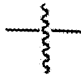
- In the present specification,
- In the present specification, the term "substitution" means that a hydrogen atom bonded to a carbon atom of a compound is changed into another substituent, and a position to be substituted is not limited as long as the position is a position at which the hydrogen atom is substituted, that is, a position at which the substituent may be substituted, and when two or more substituents are substituted, the two or more substituents may be the same as or different from each other.
- In the present specification, the term "substituted or unsubstituted" means being substituted with one or more substituents selected from the group consisting of deuterium; a halogen group; a nitrile group; an alkyl group; a cycloalkyl group; an alkoxy group; an aryloxy group; an aryl group; and a heterocyclic group, or being substituted with a substituent to which two or more substituents among the substituents exemplified above are linked, or being unsubstituted. For example, "the substituent to which two or more substituents are linked" may be a biphenyl group. That is, the biphenyl group may also be an aryl group, and may be interpreted as a substituent to which two phenyl groups are linked.
- In the present specification, a halogen group is a fluoro group (-F), a chloro group (-Cl), a bromo group (-Br), or an iodo group (-I).
- In the present specification, the alkyl group may be straight-chained or branched, and the number of carbon atoms thereof is not particularly limited, but may be 1 to 60, and according to an exemplary embodiment, the number of carbon atoms of the alkyl group may be 1 to 40. According to another exemplary embodiment, the number of carbon atoms of the alkyl group is 1 to 20. Specific examples of the alkyl group include a methyl group, an ethyl group, a propyl group, an isopropyl group, an n-butyl group, an isobutyl group, a tert-butyl group, an n-pentyl group, an n-hexyl group, an n-heptyl group, and the like, but are not limited thereto.
- In the present specification, the above-described description on the alkyl group can be referred to, except that the alkylene group is a divalent alkyl group.
- In the present specification, a fluoroalkyl group means an alkyl group substituted with a fluoro group, and specific examples thereof include a fluoromethyl group, a difluoromethyl group, a trifluoromethyl group, a fluoroethyl group, and the like, but are not limited thereto.
- In the present specification, a cycloalkyl group is not particularly limited, but may have 3 to 60 carbon atoms, and according to an exemplary embodiment, the number of carbon atoms of the cycloalkyl group is 3 to 40. According to another exemplary embodiment, the number of carbon atoms of the cycloalkyl group is 3 to 20. Specific examples of the cycloalkyl group include a cyclopropyl group, a cyclobutyl group, a cyclopentyl group, a cyclohexyl group, a cycloheptyl group, a cyclooctyl group, and the like, but are not limited thereto.
- In the present specification, the alkoxy group may be straight-chained or branched. The number of carbon atoms of the alkoxy group is not particularly limited, but may be 1 to 20. Specific examples of the alkoxy group include a methoxy group, an ethoxy group, an n-propoxy group, an n-butoxy group, a tert-butoxy group, an n-pentyloxy group, an n-hexyloxy group, an n-octyloxy group, an n-nonyloxy group, an n-decyloxy group, and the like, but are not limited thereto.
- In the present specification, the aryl group is not particularly limited, but may have 6 to 60 carbon atoms, and may be a monocyclic aryl group or a polycyclic aryl group. According to an exemplary embodiment, the number of carbon atoms of the aryl group is 6 to 30. According to an exemplary embodiment, the number of carbon atoms of the aryl group is 6 to 20. Examples of the monocyclic aryl group include a phenyl group, a biphenyl group, a terphenyl group, and the like, but are not limited thereto. Examples of the polycyclic aryl group include a naphthyl group, an anthracenyl group, a phenanthrenyl group, a pyrenyl group, a perylenyl group, a triphenyl group, a chrysenyl group, a fluorenyl group, and the like, but are not limited thereto.
- In the present specification, a fluorenyl group may be substituted, and two substituents may be bonded to each other to form a spiro structure.
- When the fluorenyl group is substituted, the fluorenyl group may be a spirofluorenyl group such as


- In the present specification, the above-described description on the aryl group can be referred to, except that the arylene group is a divalent aryl group.
- In the present specification, a heterocyclic group is a heterocyclic group including one or more of N, O, P, S, Si, or Se as a heteroatom, and the number of carbon atoms thereof is not particularly limited, but may be 2 to 60. According to an exemplary embodiment, the number of carbon atoms of the heterocyclic group is 2 to 30. According to another exemplary embodiment, the number of carbon atoms of the heterocyclic group is 2 to 20. Examples of the heterocyclic group include a pyridyl group, a pyrrole group, a pyrimidyl group, a pyridazinyl group, a furanyl group, a thiophene group, a benzothiophene group, a benzofuran group, a dibenzothiophene group, a dibenzofuran group, and the like, but are not limited thereto.
- In the present specification, the above-described description on the heterocyclic group may be applied to a heteroaryl group except for an aromatic heteroaryl group.
- In the present specification, the above-described description on the aryl group is applied to an aryl group in the aryloxy group.
- According to an exemplary embodiment of the present specification, R1 to R19 are the same as or different from each other, and are each independently hydrogen, deuterium, a fluoro group, a fluoroalkyl group, a cyano group, or a substituted or unsubstituted alkyl group.
- In an exemplary embodiment of the present specification, R1 to R19 are the same as or different from each other, and are each independently hydrogen, deuterium, a fluoro group, a fluoroalkyl group having 1 to 10 carbon atoms, a cyano group, or a substituted or unsubstituted alkyl group having 1 to 10 carbon atoms.
- In an exemplary embodiment of the present specification, R1 to R19 are the same as or different from each other, and are each independently a fluoro group or a fluoroalkyl group.
- In another exemplary embodiment, R1 to R19 are the same as or different from each other, and are each independently a fluoro group or a fluoroalkyl group having 1 to 10 carbon atoms.
- According to another exemplary embodiment, R1 to R19 are the same as or different from each other, and are each independently a fluoro group or a trifluoromethyl group.
- According to still another exemplary embodiment, R1 to R15 are the same as or different from each other, and are each independently a fluoro group or a trifluoromethyl group.
- According to yet another exemplary embodiment, R3, R8 and R13 are a trifluoromethyl group.
- According to yet another exemplary embodiment, R1, R2, R4 to R7, R9 to R12, R14 and R15 are a fluoro group.
- In an exemplary embodiment of the present specification, m1 is an integer from 1 to 3, and when m1 is 2 or higher, two or more substituents in the parenthesis are the same as or different from each other.
- According to yet another exemplary embodiment, m1 is 1 or 2, and when m1 is 2, two substituents in the parenthesis are the same as or different from each other.
- According to an exemplary embodiment of the present specification,
Chemical Formula 1 is represented by the followingChemical Formula 


- In
Chemical Formulae - R1 to R15, Ar, X and n1 are the same as those defined in
Chemical Formula 1, and - R21 to R28 are the same as or different from each other, and are each independently hydrogen, deuterium, a fluoro group, a fluoroalkyl group, a cyano group, or a substituted or unsubstituted alkyl group.
- According to an exemplary embodiment of the present specification, R21 to R28 are the same as or different from each other, and are each independently a fluoro group or a fluoroalkyl group.
- According to another exemplary embodiment, R21 to R28 are the same as or different from each other, and are each independently a fluoro group or a fluoroalkyl group having 1 to 10 carbon atoms.
- In another exemplary embodiment, R21 to R28 are the same as or different from each other, and are each independently a fluoro group or a trifluoromethyl group.
- In still another exemplary embodiment, R21 to R28 are a fluoro group.
- In an exemplary embodiment of the present specification, Ar is a substituted or unsubstituted (n1+1)-valent aryl group.
- According to still another exemplary embodiment, Ar is a substituted or unsubstituted (n1+1)-valent aryl group having 6 to 30 carbon atoms.
- In another exemplary embodiment, Ar is a (n1+1)-valent aryl group having 6 to 30 carbon atoms.
- According to yet another exemplary embodiment, Ar is a substituted or unsubstituted (n1+1)-valent phenyl group.
- In still another exemplary embodiment, Ar is a (n1+1)-valent phenyl group.
- In an exemplary embodiment of the present specification,
Chemical Formula 1 is represented by the followingChemical Formula 4.

- In
Chemical Formula 4, - R1 to R19, X, n1 and m1 are the same as those defined in
Chemical Formula 1, - R101 is hydrogen; deuterium; a halogen group; a substituted or unsubstituted alkyl group; a substituted or unsubstituted alkoxy group; a substituted or unsubstituted aryl group; or a substituted or unsubstituted heteroaryl group, and
- n2 is an integer from 0 to 4, and when n2 is 2 or higher, two or more R101's are the same as or different from each other, and n1+n2 is 1 to 5.
- According to an exemplary embodiment of the present specification, R101 is hydrogen or deuterium.
- In an exemplary embodiment of the present specification, n2 is an integer from 0 to 3.
- According to an exemplary embodiment of the present specification,
Chemical Formula 2 is represented by the followingChemical Formula 


- In
Chemical Formulae - R1 to R15, X and n1 are the same as those defined in
Chemical Formula 1, - R21 to R28 are the same as or different from each other, and are each independently a fluoro group or a fluoroalkyl group,
- R101 is hydrogen; deuterium; a halogen group; a substituted or unsubstituted alkyl group; a substituted or unsubstituted alkoxy group; a substituted or unsubstituted aryl group; or a substituted or unsubstituted heteroaryl group, and
- n2 is an integer from 0 to 4, and when n2 is 2 or higher, two or more R101's are the same as or different from each other, and n1+n2 is 1 to 5.
- According to an exemplary embodiment of the present specification, X is a curing group. In this case, the curing group means a substituent in which the curing groups of compounds adjacent to each other chemically react with each other to form a bond, whereby the molecule becomes large and the curing can be performed, and the curing group may also be referred to as an addition reaction capable group, or a cross-linking group in which compounds adjacent to each other form a cross-linkage.
- In an exemplary embodiment of the present specification, the curing group is not particularly limited as long as the curing groups of compounds adjacent to each other can chemically react, but may include at least one of an aliphatic ring group capable of a ring-opening reaction and an ethylenically unsaturated group.
- In an exemplary embodiment of the present specification, the curing group is a compound which is any one of the following Chemical Formulae 7-1 to 7-5:


- In Chemical Formulae 7-1 to 7-5,
- L1 is a direct bond; O; S; a substituted or unsubstituted (c+1)-valent alkyl group; a substituted or unsubstituted (c+1)-valent aryl group; or a substituted or unsubstituted (c+1)-valent heterocyclic group,
- L2 to L5 are the same as or different from each other, and are each independently a direct bond; O; S; a substituted or unsubstituted alkylene group; a substituted or unsubstituted arylene group; or a substituted or unsubstituted divalent heterocyclic group,
- L6 is O or a substituted or unsubstituted alkylene group,
- R200 to R202 and R209 to R211 are the same as or different from each other, and are each independently hydrogen, deuterium, a halogen group or a substituted or unsubstituted alkyl group,
- R203 is a substituted or unsubstituted alkyl group,
- R204 to R207 are the same as or different from each other, and are each independently hydrogen, deuterium or a substituted or unsubstituted alkyl group,
- R208 is a substituted or unsubstituted alkyl group or a substituted or unsubstituted aryl group,
- c is an integer of 1 or 2, and when c is 2, structures in the parenthesis are the same as or different from each other,
- k1 to k5 are each an integer from 1 to 4,
- when k1 is 2 or higher, L1's are the same as or different from each other,
- when k2 is 2 or higher, L2's are the same as or different from each other,
- when k3 is 2 or higher, L3's are the same as or different from each other,
- when k4 is 2 or higher, L4's are the same as or different from each other, and
- when k5 is 2 or higher, L5's are the same as or different from each other.
- In an exemplary embodiment of the present specification, when k1 is 2 or higher, the case where O is continuously bonded to form -O-O-, or the case where S is continuously bonded to form -S-S- or form -O-S- is excluded from L1.
- In an exemplary embodiment of the present specification, when k2 is 2 or higher, the case where O is continuously bonded to form -O-O-, or the case where S is continuously bonded to form -S-S- or form -O-S- is excluded from L2.
- In an exemplary embodiment of the present specification, when k3 is 2 or higher, the case where O is continuously bonded to form -O-O-, or the case where S is continuously bonded to form -S-S- or form -O-S- is excluded from L3.
- In an exemplary embodiment of the present specification, when k4 is 2 or higher, the case where O is continuously bonded to form -O-O-, or the case where S is continuously bonded to form -S-S- or form -O-S- is excluded from L4.
- In an exemplary embodiment of the present specification, when k5 is 2 or higher, the case where O is continuously bonded to form -O-O-, or the case where S is continuously bonded to form -S-S- or form -O-S- is excluded from L5.
- According to an exemplary embodiment of the present specification, X is a substituted or unsubstituted alkenyl group; or an aryl group which is substituted with a substituted or unsubstituted alkenyl group.
- According to an exemplary embodiment of the present specification, X is a substituted or unsubstituted alkenyl group having 2 to 10 carbon atoms; or an aryl group which is substituted with a substituted or unsubstituted alkenyl group having 2 to 10 carbon atoms.
- According to an exemplary embodiment of the present specification, X is a substituted or unsubstituted alkenyl group having 2 to 5 carbon atoms; or an aryl group which is substituted with a substituted or unsubstituted alkenyl group having 2 to 5 carbon atoms.
- According to an exemplary embodiment of the present specification, X is a substituted or unsubstituted ethenyl group; a substituted or unsubstituted propenyl group; or a substituted or unsubstituted butenyl group; or an aryl group which is substituted with a substituted or unsubstituted ethenyl group, a substituted or unsubstituted propenyl group, or a substituted or unsubstituted butenyl group.
- According to another exemplary embodiment of the present specification, X is a vinyl group (-CH=CH2) or an aryl group which is substituted with a vinyl group (-CH=CH2).
- In another exemplary embodiment, X is a vinyl group (-CH=CH2), or an aryl group having 6 to 30 carbon atoms, which is substituted with one or more vinyl groups (-CH=CH2).
- According to still another exemplary embodiment, X is a vinyl group (-CH=CH2), a phenyl group which is substituted with one or more vinyl groups (-CH=CH2), or a naphthyl group which is substituted with one or more vinyl groups (-CH=CH2).
- According to yet another exemplary embodiment, X is a vinyl group (-CH=CH2), a phenyl group which is substituted with one vinyl group (-CH=CH2), a phenyl group which is substituted with two vinyl groups (-CH=CH2), or a naphthyl group which is substituted with a vinyl group (-CH=CH2).
- In still another exemplary embodiment, X is selected from the following structures.


- In the present specification, the compound of
Chemical Formula 1 is characterized in that one of the four substituents bonded to boron is a boron compound having an end group of -Ar-(X)n1 (X = a curing group) and has an asymmetric structure by the end group. Since the curing group X is located in the outer shell, the compound ofChemical Formula 1 has a low curing temperature, and is easily cured and advantageous for maintaining curing compared to the symmetric compound. In particular, the case where the curing group X is a vinyl group or an aryl group which is substituted with a vinyl group has an advantage in that the compound is relatively easily cured. In particular, the case has an advantage of having a curing temperature lower than that of a vinyl group which is substituted with a methyl group (
- According to an exemplary embodiment of the present specification, n1 is an integer from 1 to 5, and when n1 is 2 or higher, two or more substituents in the parenthesis are the same as or different from each other.
- In another exemplary embodiment, n1 is 1 or 2, and when n1 is 2, two X's are the same as or different from each other.
- In an exemplary embodiment of the present specification,
Chemical Formula 1 is represented by any one of the following compounds.


- According to an exemplary embodiment of the present specification, the compound further includes a counterion. In this case, the type of counterion is not particularly limited, and may include any one cation from the following structural formulae.


- In the structural formulae, X1 to X32 are the same as or different from each other, and are each independently hydrogen; deuterium; a cyano group; a nitro group; a halogen group; -COOR104; a substituted or unsubstituted alkyl group; a substituted or unsubstituted alkoxy group; a substituted or unsubstituted cycloalkyl group; a substituted or unsubstituted fluoroalkyl group; or a substituted or unsubstituted aryl group, or a curing group selected from the group of following curing groups, R104 is hydrogen; deuterium; or a substituted or unsubstituted alkyl group,
- a is 1 or 2, b is 0 or 1, and a + b =2,
- X100 to X124 are the same as or different from each other, and are each independently hydrogen; deuterium; a cyano group; a nitro group; a halogen group; -COOR105; a substituted or unsubstituted alkyl group; a substituted or unsubstituted alkoxy group; a substituted or unsubstituted cycloalkyl group; a substituted or unsubstituted fluoroalkyl group; or a substituted or unsubstituted aryl group, or a curing group selected from the group of the following curing groups,
- R105 is a substituted or unsubstituted alkyl group,
- [Group of curing groups]


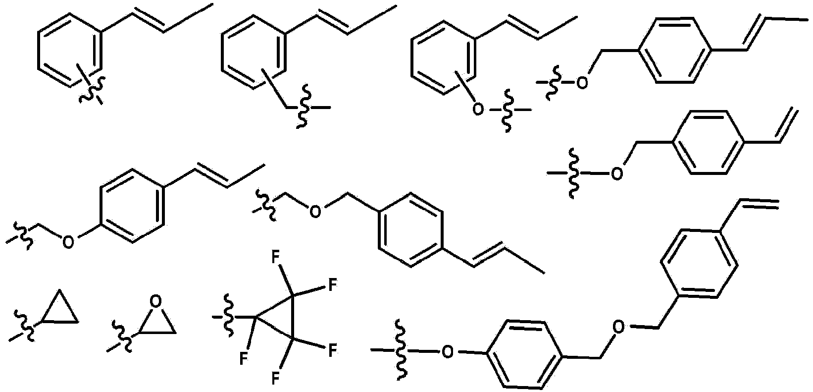
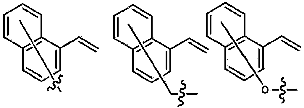

- R30 to R32 are the same as or different from each other, and are each independently a substituted or unsubstituted alkyl group; a substituted or unsubstituted alkenyl group; a substituted or unsubstituted alkynyl group; a substituted or unsubstituted cycloalkyl group; a substituted or unsubstituted aryl group; or a substituted or unsubstituted heterocyclic group, or groups adjacent to each other are bonded to each other to form a substituted or unsubstituted ring, and
-

- According to an exemplary embodiment of the present specification, R30 to R32 are a substituted or unsubstituted alkyl group having 1 to 10 carbon atoms; a substituted or unsubstituted alkenyl group having 2 to 10 carbon atoms; a substituted or unsubstituted alkynyl group having 2 to 10 carbon atoms; a substituted or unsubstituted cycloalkyl group having 3 to 10 carbon atoms; a substituted or unsubstituted aryl group having 6 to 20 carbon atoms; or a substituted or unsubstituted heterocyclic group having 2 to 20 carbon atoms, or groups adjacent to each other are bonded to each other to form a substituted or unsubstituted hetero ring.
- According to an exemplary embodiment of the present specification, when groups adjacent to each other in R30 to R32 are bonded to each other, a hetero ring including a central S is formed by a hetero element, and the hetero ring may be substituted or unsubstituted.
- According to an exemplary embodiment of the present specification, when groups adjacent to each other in R30 to R32 are bonded to each other, tetrahydrothiophene, thiophene, benzothiophene or dibenzothiophene may be formed, and the ring may be substituted or unsubstituted.
- According to an exemplary embodiment of the present specification, the cation may include any one cation of the following structural formulae.

- X300 to X317 are the same as or different from each other, and are each independently a substituted or unsubstituted alkyl group; a substituted or unsubstituted alkenyl group; a substituted or unsubstituted alkynyl group; a substituted or unsubstituted cycloalkyl group; a substituted or unsubstituted aryl group; or a substituted or unsubstituted heterocyclic group, or groups adjacent to each other are bonded to each other to form a substituted or unsubstituted ring.
- According to an exemplary embodiment of the present specification, the structural formulae of the cation may be any one of the following cations.


- According to an exemplary embodiment of the present specification, the compound is represented by any one of the following structural formulae.


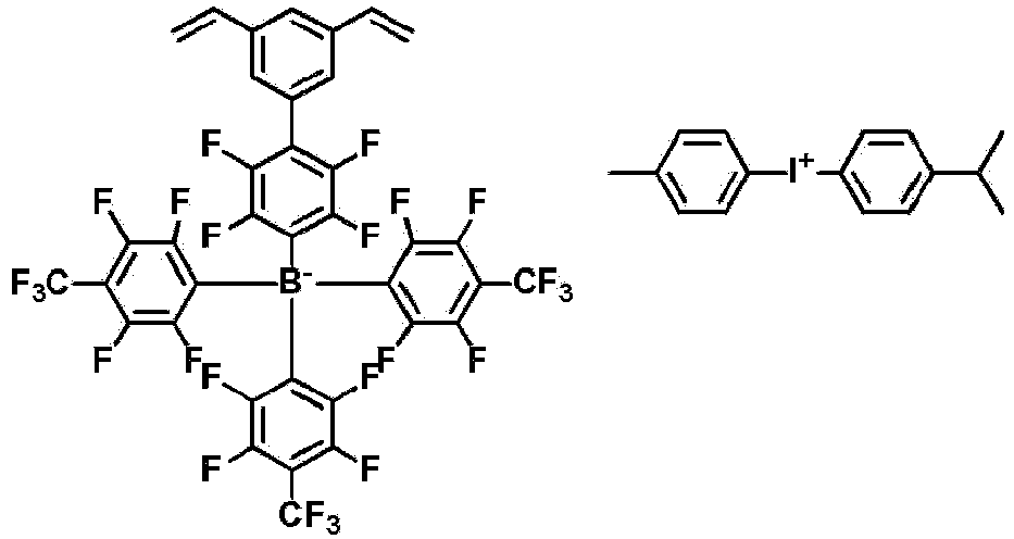


- The compound according to an exemplary embodiment of the present specification may be prepared in the same manner as in a preparation method to be described below. In the preparation method to be described below, the substituent may be bonded by a method known in the art, and the type and position of the substituent or the number of substituents may be changed according to the technology known in the art.
- In an exemplary embodiment of the present specification, provided is a coating composition including the above-described compound.
- In an exemplary embodiment of the present specification, the coating composition includes the compound of
Chemical Formula 1 and a solvent. - In an exemplary embodiment of the present specification, the coating composition may be in a liquid phase. The "liquid phase" means that the composition is in a liquid state at room temperature under atmospheric pressure.
- In an exemplary embodiment of the present specification, the solvent is exemplified as, for example, a chlorine-based solvent such as chloroform, methylene chloride, 1,2-dichloroethane, 1,1,2-trichloroethane, chlorobenzene, and o-dichlorobenzene; an ether-based solvent such as tetrahydrofuran and dioxane; an aromatic hydrocarbon-based solvent such as toluene, xylene, trimethylbenzene, and mesitylene; an aliphatic hydrocarbon-based solvent such as cyclohexane, methylcyclohexane, n-pentane, n-hexane, n-heptane, n-octane, n-nonane, and n-decane; a ketone-based solvent such as acetone, methyl ethyl ketone, cyclohexanone, isophorone, tetralone, decalone, and acetylacetone; an ester-based solvent such as ethyl acetate, butyl acetate, and ethyl cellosolve acetate; a polyhydric alcohol such as ethylene glycol, ethylene glycol monobutyl ether, ethylene glycol monoethyl ether, ethylene glycol monomethyl ether, dimethoxy ethane, propylene glycol, diethoxymethane, triethylene glycol monoethyl ether, glycerin, and 1,2-hexanediol, and derivatives thereof; an alcohol-based solvent such as methanol, ethanol, propanol, isopropanol, and cyclohexanol; a sulfoxide-based solvent such as dimethyl sulfoxide; an amide-based solvent such as N-methyl-2-pyrrolidone and N,N-dimethylformamide; and tetralin, but the solvent is sufficient as long as the solvent may dissolve or disperse the compound of Chemical Formula 1 according to an exemplary embodiment of the present invention, and is not limited thereto.
- In another exemplary embodiment, the solvents may be used either alone or in a mixture of two or more solvents.
- In an exemplary embodiment of the present specification, the coating composition may further include an additional compound along with the compound of
Chemical Formula 1. - According to another exemplary embodiment, the coating composition includes the compound of
Chemical Formula 1 as a dopant, and includes the additional compound as a host. In this case, a mass ratio (compound of Chemical Formula 1 : additional compound) of the compound ofChemical Formula 1 and the additional compound may be 1 : 9 to 5 : 5. - In another exemplary embodiment, the additional compound may be an arylamine-based compound, and may be an arylamine-based compound in which a vinyl group is substituted. When the compound of
Chemical Formula 1 and the arylamine-based compound in which a vinyl group is substituted are used together, there is an advantage in that reactivity is good because the curing temperatures are similar to each other. - An example of the additional compound includes the following compounds, but is not limited thereto.


- The viscosity of the coating composition is 2 cP to 15 cP at room temperature (about 25°C). When the above viscosity is satisfied, a device is easily manufactured.
- The present specification also provides an organic light emitting device formed by using the coating composition.
- The organic light emitting device according to the present specification may be included and used in various electronic devices. For example, the electronic device may be a display panel, a touch panel, a solar module, a lighting device, and the like, and is not limited thereto.
- In an exemplary embodiment of the present specification, the organic light emitting device includes: a first electrode; a second electrode; and an organic material layer having one or more layers provided between the first electrode and the second electrode, in which one or more layers of the organic material layer include the coating composition or a cured product thereof, and the cured product of the coating composition is in a state where the coating composition is cured by a heat treatment or a light treatment.
- In an exemplary embodiment of the present specification, the organic material layer including the coating composition or the cured product thereof is a hole transport layer or a hole injection layer.
- In an exemplary embodiment of the present specification, the organic material layer including the coating composition or the cured product thereof is an electron transport layer or an electron injection layer.
- In another exemplary embodiment, the organic material layer including the coating composition or the cured product thereof is a light emitting layer.
- In still another exemplary embodiment, the organic material layer including the coating composition or the cured product thereof is a light emitting layer, and the light emitting layer includes the compound as a host of the light emitting layer.
- In yet another exemplary embodiment, the organic material layer including the coating composition or the cured product thereof is a light emitting layer, and the light emitting layer includes the compound as a dopant of the light emitting layer.
- In an exemplary embodiment of the present specification, the organic light emitting device further includes one or two or more layers selected from the group consisting of a hole injection layer, a hole transport layer, an electron transport layer, an electron injection layer, an electron blocking layer, a hole blocking layer, a layer which simultaneously transports and injects holes, and a layer which simultaneously transports and injects electrons.
- In an exemplary embodiment of the present specification, the first electrode is an anode, and the second electrode is a cathode.
- According to another exemplary embodiment, the first electrode is a cathode, and the second electrode is an anode.
- In another exemplary embodiment, the organic light emitting device may be a normal type organic light emitting device in which an anode, an organic material layer having one or more layers, and a cathode are sequentially stacked on a substrate.
- In still another exemplary embodiment, the organic light emitting device may be an inverted type organic light emitting device in which a cathode, an organic material layer having one or more layers, and an anode are sequentially stacked on a substrate.
- The organic material layer of the organic light emitting device of the present specification may also be composed of a single-layered structure, but may be composed of a multi-layered structure in which two or more organic material layers are stacked. For example, the organic light emitting device of the present disclosure may have a structure including a hole injection layer, a hole transport layer, a light emitting layer, an electron transport layer, an electron injection layer, a hole blocking layer, an electron blocking layer, a layer which simultaneously transports and injects holes, a layer which simultaneously transports and injects electrons, and the like as an organic material layer. However, the structure of the organic light emitting device is not limited thereto, and may include a fewer number of organic layers.
- For example, the structure of the organic light emitting device according to an exemplary embodiment of the present specification is exemplified in
FIG. 1 . -
FIG. 1 exemplifies a structure of an organic light emitting device in which ananode 201, ahole injection layer 301, ahole transport layer 401, alight emitting layer 501, alayer 601 which simultaneously transports and injects electrons, and acathode 701 are sequentially stacked on asubstrate 101. -
FIG. 1 exemplifies an organic light emitting device, and the organic light emitting device is not limited thereto. - When the organic light emitting device includes a plurality of organic material layers, the organic material layers may be formed of the same material or different materials.
- The organic light emitting device of the present specification may be manufactured by the materials and methods known in the art, except that one or more layers of the organic material layer are formed by using the coating composition including the compound of
Chemical Formula 1. - For example, the organic light emitting device of the present specification may be manufactured by sequentially stacking an anode, an organic material layer, and a cathode on a substrate. In this case, the organic light emitting device may be manufactured by depositing a metal or a metal oxide having conductivity, or an alloy thereof on a substrate to form an anode, forming an organic material layer including a hole injection layer, a hole transport layer, a light emitting layer, and a layer which simultaneously transports and injects electrons thereon through a solution process, a deposition process, and the like, and then depositing a material, which may be used as a cathode, thereon, by using a physical vapor deposition (PVD) method such as sputtering or e-beam evaporation. In addition to the method described above, an organic light emitting device may be made by sequentially depositing a cathode material, an organic material layer, and an anode material on a substrate.
- The present specification also provides a method for manufacturing an organic light emitting device formed by using the coating composition.
- Specifically, in an exemplary embodiment of the present specification, the method includes: preparing a substrate; forming a first electrode on the substrate; forming an organic material layer having one or more layers on the first electrode; and forming a second electrode on the organic material layer, in which the forming of the organic material layer includes forming an organic material layer having one or more layers by using the coating composition.
- In an exemplary embodiment of the present specification, the forming of the organic material layer having one or more layers by using the coating composition uses a spin coating method.
- In another exemplary embodiment, the forming of the organic material layer having one or more layers by using the coating composition uses a printing method.
- In an exemplary embodiment state of the present specification, examples of the printing method include inkjet printing, nozzle printing, offset printing, transfer printing or screen printing, and the like, but are not limited thereto.
- A solution process is suitable for the coating composition according to an exemplary embodiment of the present specification due to the structural characteristics thereof, so that the organic material layer may be formed by a printing method, and as a result, there is an economic effect in terms of time and costs when a device is manufactured.
- In an exemplary embodiment of the present specification, the forming of the organic material layer having one or more layers by using the coating composition includes: coating the coating composition on the first electrode or the organic material layer having one or more layers; and heat-treating or light-treating the coated coating composition.
- In an exemplary embodiment of the present specification, the heat-treating of the coated coating composition may be performed through a heat treatment, and the heat treatment temperature in the heat-treating of the coated coating composition may be 85°C to 250°C, may be 100°C to 250°C according to an exemplary embodiment, and may be 150°C to 250°C in another exemplary embodiment.
- In another exemplary embodiment, the heat treatment time in the heat-treating of the coated composition may be 1 minute to 2 hours, may be 10 minutes to 2 hours according to an exemplary embodiment, and may be 10 minutes to 90 minutes in another exemplary embodiment.
- When the forming of the organic material layer formed by using the coating composition includes the heat-treating or light-treating of the coated coating composition, a plurality of the compounds included in the coating composition may form a cross-linkage, thereby providing an organic material layer including a thin-filmed structure. In this case, it is possible to prevent the organic material layer from being dissolved, morphologically affected or decomposed by a solvent when another layer is stacked on the surface of the organic material layer formed by using the coating composition.
- Therefore, when the organic material layer formed by using the coating composition is formed by a method including the heat-treating or light-treating of the coated coating composition, resistance to a solvent is increased, so that a plurality of layers may be formed by repeatedly performing solution deposition and cross-linking methods, and stability is increased, so that the service life characteristic of the device may be increased.
- As the anode material, materials having a high work function are usually preferred so as to facilitate the injection of holes into an organic material layer. Specific examples of the anode material which may be used in the present disclosure include: a metal such as vanadium, chromium, copper, zinc, and gold, or an alloy thereof; a metal oxide such as zinc oxide, indium oxide, indium tin oxide (ITO), and indium zinc oxide (IZO); a combination of a metal and an oxide, such as ZnO:Al or SnO2:Sb; a conductive polymer such as poly(3-methylthiophene), poly[3,4-(ethylene-1,2-dioxy)thiophene] (PEDOT), polypyrrole, and polyaniline; and the like, but are not limited thereto.
- As the cathode material, materials having a low work function are usually preferred so as to facilitate the injection of electrons into an organic material layer. Specific examples of the cathode material include: a metal such as barium, magnesium, calcium, sodium, potassium, titanium, indium, yttrium, lithium, gadolinium, aluminum, silver, tin, and lead, or an alloy thereof; a multi-layer structured material, such as LiF/Al or LiO2/Al; and the like, but are not limited thereto.
- The hole injection layer is a layer which injects holes from an electrode, and a hole injection material is preferably a compound which has a capability of transporting holes, and thus has an effect of injecting holes at an anode and an excellent effect of injecting holes into a light emitting layer or a light emitting material, prevents excitons produced from the light emitting layer from moving to an electron injection layer or an electron injection material, and is also excellent in the ability to form a thin film. The highest occupied molecular orbital (HOMO) of the hole injection material is preferably a value between the work function of the anode material and the HOMO of the neighboring organic material layer. Specific examples of the hole injection material include the above-described compound of
Chemical Formula 1, metal porphyrin, oligothiophene, arylamine-based organic materials, hexanitrile hexaazatriphenylene-based organic materials, quinacridone-based organic materials, perylenebased organic materials, anthraquinone, polyaniline-based and polythiophene-based electrically conductive polymers, and the like, but are not limited thereto. - The hole transport layer is a layer which accepts holes from a hole injection layer and transports the holes to a light emitting layer, and a hole transport material is suitably a material having high hole mobility which may accept holes from an anode or a hole injection layer and transfer the holes to a light emitting layer. Specific examples thereof include arylamine-based organic materials, conductive polymers, block copolymers having both conjugated portions and non-conjugated portions, and the like, but are not limited thereto.
- The layer which simultaneously transports and injects holes may include materials for the hole transport layer and the hole injection layer described above.
- The light emitting material is a material which may accept holes and electrons from a hole transport layer and an electron transport layer, respectively, and combine the holes and the electrons to emit light in a visible ray region, and is preferably a material having high quantum efficiency to fluorescence or phosphorescence. Specific examples thereof include: 8-hydroxy-quinoline aluminum complexes (Alq3); carbazole-based compounds; dimerized styryl compounds; BAlq; 10-hydroxybenzoquinoline-metal compounds; benzoxazole-based, benzothiazole-based and benzimidazole-based compounds; poly(p-phenylenevinylene) (PPV)-based polymers; spiro compounds; polyfluorene, lubrene, and the like, but are not limited thereto.
- The light emitting layer may include a host material and a dopant material. Examples of the host material include fused aromatic ring derivatives, or hetero ringcontaining compounds, and the like. Specifically, examples of the fused aromatic ring derivatives include anthracene derivatives, pyrene derivatives, naphthalene derivatives, pentacene derivatives, phenanthrene compounds, fluoranthene compounds, and the like, and examples of the hetero ringcontaining compounds include carbazole derivatives, dibenzofuran derivatives, ladder-type furan compounds, pyrimidine derivatives, and the like, but the examples thereof are not limited thereto.
- Examples of the dopant material include an aromatic amine derivative, a styrylamine compound, a boron complex, a fluoranthene compound, a metal complex, and the like. Specifically, the aromatic amine derivative is a fused aromatic ring derivative having a substituted or unsubstituted arylamino group, and examples thereof include a pyrene, an anthracene, a chrysene, a periflanthene, and the like, which have an arylamino group, and the styrylamine compound is a compound in which a substituted or unsubstituted arylamine is substituted with at least one arylvinyl group, and one or two or more substituents selected from the group consisting of an aryl group, a silyl group, an alkyl group, a cycloalkyl group, and an arylamino group is or are substituted or unsubstituted. Specific examples thereof include styrylamine, styryldiamine, styryltriamine, styryltetramine, and the like, but are not limited thereto. Further, examples of the metal complexes include an iridium complex, a platinum complex, and the like, but are not limited thereto.
- The electron transport layer is a layer which accepts electrons from an electron injection layer and transports the electrons to a light emitting layer, and an electron transport material is suitably a material having high electron mobility which may proficiently accept electrons from a cathode and transfer the electrons to a light emitting layer. Specific examples thereof include: Al complexes of 8-hydroxyquinoline; complexes including Alq3; organic radical compounds; hydroxyflavone-metal complexes, and the like, but are not limited thereto. The electron transport layer may be used with any desired cathode material, as used according to the related art. In particular, appropriate examples of the cathode material are a typical material which has a low work function, followed by an aluminum layer or a silver layer. Specific examples thereof include cesium, barium, calcium, ytterbium, and samarium, in each case followed by an aluminum layer or a silver layer.
- The electron injection layer is a layer which injects electrons from an electrode, and an electron injection material is preferably a compound which has a capability of transporting electrons, has an effect of injecting electrons from a cathode and an excellent effect of injecting electrons into a light emitting layer or a light emitting material, prevents excitons produced from the light emitting layer from moving to a hole injection layer, and is also excellent in the ability to form a thin film. Specific examples thereof include fluorenone, anthraquinodimethane, diphenoquinone, thiopyran dioxide, oxazole, oxadiazole, triazole, imidazole, perylenetetracarboxylic acid, fluorenylidene methane, anthrone, and the like, and derivatives thereof, metal complex compounds, nitrogen-containing 5-membered ring derivatives, and the like, but are not limited thereto.
- The layer which simultaneously transports and injects electrons may include materials for the electron transport layer and the electron injection layer described above.
- Examples of the metal complex compounds include 8-hydroxyquinolinato lithium, bis(8-hydroxyquinolinato) zinc, bis(8-hydroxyquinolinato) copper, bis(8-hydroxyquinolinato) manganese, tris(8-hydroxyquinolinato) aluminum, tris(2-methyl-8-hydroxyquinolinato) aluminum, tris(8-hydroxyquinolinato) gallium, bis(10-hydroxybenzo[h]quinolinato) beryllium, bis(10-hydroxybenzo[h]quinolinato) zinc, bis(2-methyl-8-quinolinato) chlorogallium, bis(2-methyl-8-quinolinato)(o-cresolato) gallium, bis(2-methyl-8-quinolinato)(1-naphtholato) aluminum, bis(2-methyl-8-quinolinato)(2-naphtholato) gallium, and the like, but are not limited thereto.
- The hole blocking layer is a layer which blocks holes from reaching a cathode, and may be generally formed under the same conditions as those of the hole injection layer. Specific examples thereof include oxadiazole derivatives or triazole derivatives, phenanthroline derivatives, BCP, aluminum complexes, and the like, but are not limited thereto.
- The electron blocking layer is a layer which blocks electrons from reaching an anode, and materials known in the art may be used.
- The organic light emitting device according to the present specification may be a top emission type, a bottom emission type, or a dual emission type according to the materials to be used.
- Hereinafter, the present specification will be described in detail with reference to Examples for specifically describing the present specification.
However, the Examples according to the present specification may be modified in various forms, and it is not interpreted that the scope of the present specification is limited to the Examples described below. The Examples of the present specification are provided to more completely explain the present specification to a person with ordinary skill in the art. -

- 5 g (16.2406 mmol) of 1,2-dibromotetrafluorobenzene, 1,201 mg (8.1203 mmol) of 4-vinylphenylboronic acid, 4,137 mg (19.4487 mmol, 10 mL of distilled water) of potassium phosphate tribasic (K3PO4) and 40 mL of 1,2-dimethoxyethane were put into a flask, and the atmosphere of the flask was substituted with nitrogen for 30 minutes. 375 mg (0.3248 mmol) of tetrakis(triphenylphosphine)palladium(0) (Pd(PPh3)4) was added to the flask, and the resulting mixture was stirred under a condition of 80°C for 8 hours. The flask was cooled to room temperature, 40 mL of water was added thereto, and the product was extracted three times with 30 mL of ethyl acetate to obtain an organic layer. The resulting organic layer was dried over magnesium sulfate and filtered to obtain a filtrate. An organic solvent was removed and a residue was purified by column with 100% hexane to obtain 1.7 g of a target compound 4-bromo-2,3,5,6-tetrafluoro-4'-vinyl-1,1'-biphenyl.
-

- 4,574 mg (15.4026 mmol) of 1-bromo-2,3,5,6-tetrafluoro-4-(trifluoromethyl)benzene and 50 mL of diethyl ether were put into a flask, and the resulting mixture was stirred under a condition of -78°C for 1 hour. 6.16 mL (15.4206 mmol, 2.5 M) of n-butyllithium (n-BuLi) was slowly added to the flask, and the resulting mixture was stirred under a condition of -78°C for 1 hour. 5.13 mL (5.1342 mmol, 1 M heptane) of trichloroborane was slowly added thereto at -78°C and the resulting mixture was stirred for 1 hour to obtain a tris(2,3,5,6-tetrafluoro-4-(trifluoromethyl)phenyl)borane solution. This solution was used in the next reaction at -78°C without any purification process.
-

- 1.7 g (5.1342 mmol) of 4-bromo-2,3,5,6-tetrafluoro-4'-vinyl-1,1'-biphenyl and 17 mL of diethyl ether were put into a flask, and the resulting mixture was stirred under a condition of -78°C for 30 minutes. 2.05 mL (5.1342 mmol, 2.5 M) of n-butyllithium was added thereto at -78°C, and the resulting mixture was stirred under a condition of - 78°C for 1 hour. This solution was added to the previously prepared tris(2,3,5,6-tetrafluoro-4-(trifluoromethyl)phenyl)borane solution under a condition of -78°C. The mixture was stirred overnight while being slowly and naturally warmed to room temperature. The reaction was terminated by adding 50 mL of water thereto, and the resulting product was extracted three times with 50 mL of dichloromethane to obtain an organic layer. The organic layer was dried and a residue was purified by column while changing an eluting solution from 50% and 100% ethyl acetate/hexane to 100% dichloromethane to obtain 2.6 g of a target compound lithium(2,3,5,6-tetrafluoro-4'-vinyl-[1,1'-biphenyl]-4-yl)tris(2,3,5,6-tetrafluoro-4-(trifluoromethyl)phenyl)borate.
-
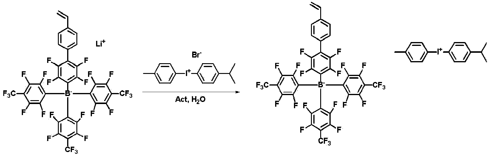
- 2.6 g (2.8256 mmol) of lithium(2,3,5,6-tetrafluoro-4'-vinyl-[1,1'-biphenyl]-4-yl)tris(2,3,5,6-tetrafluoro-4-(trifluoromethyl)phenyl)borate, 15 mL of acetone (Act) and 15 mL of water were put into a flask, and the resulting mixture was stirred for 30 minutes. 1,180 mg (2.8256 mmol) of (4-isopropylphenyl)(p-tolyl)iodonium bromide was added to the flask, and the resulting mixture was vigorously stirred for 2 hours. The resulting product was extracted three times with 15 mL of dichloromethane to obtain an organic layer, and an organic solvent was removed. A residue could be purified by column sequentially with 50% and 100% ethyl acetate/hexane and 100% dichloromethane to obtain 2.5 g of Compound 1 (4-isopropylphenyl)(p-tolyl)iodonium (2,3,5,6-tetrafluoro-4'-vinyl-[1,1'-biphenyl]-4-yl)tris(2,3,5,6-tetrafluoro-4-(trifluoromethyl)phenyl)borate.
- In
Compound 1, a view of measuring the mass of a cation is illustrated in the followingFIG. 2 , and a view of measuring the mass of an anion is illustrated in the followingFIG. 3 . -

- 5 g (10.9666 mmol) of 4,4'-dibromooctafluorobiphenyl, 1,623 mg (10.9666 mmol) of 4-vinylphenylboronic acid, 2,793 mg (13.1599 mmol, 7 mL of distilled water) of potassium phosphate tribasic and 30 mL of 1,2-dimethoxyethane were put into a flask, and the atmosphere of the flask was substituted with nitrogen for 30 minutes. 253 mg (0.2193 mmol) of tetrakis(triphenylphosphine)palladium(0) was added to the flask, and the resulting mixture was stirred under a condition of 80°C for 8 hours. The flask was cooled to room temperature, 30 mL of water was added thereto, and the product was extracted three times with 30 mL of ethyl acetate to obtain an organic layer. The resulting organic layer was dried over magnesium sulfate and filtered to obtain a filtrate. An organic solvent was removed and a residue was purified by column with 100% hexane to obtain 3 g of a target compound 4-bromo-2,2',3,3',5,5',6,6'-octafluoro-4"-vinyl-1,1':4',1"-terphenyl).
-

- A tris(2,3,5,6-tetrafluoro-4-(trifluoromethyl)phenyl)borane solution was prepared as in the above-described Synthesis Example 1-2.
- 3 g (6.2608 mmol) of 4-bromo-2,2',3,3',5,5',6,6'-octafluoro-4"-vinyl-1,1':4',1"-terphenyl and 20 mL of diethyl ether were put into a flask, and the resulting mixture was stirred under a condition of -78°C for 30 minutes. 2.50 mL (6.2608 mmol, 2.5 M) of n-butyllithium was added to the flask at -78°C, and the resulting mixture was stirred for 1 hour. The solution of the flask was slowly added to the tris(2,3,5,6-tetrafluoro-4-(trifluoromethyl)phenyl)borane solution at -78°C prepared in another flask. The mixture was stirred overnight while being slowly and naturally warmed to room temperature. The reaction was terminated by adding 20 mL of water thereto, and the resulting product was extracted three times with 20 mL of dichloromethane to obtain an organic layer. The organic layer was dried and a residue was purified by column while changing an eluting solution from 50% and 100% ethyl acetate/hexane to 100% dichloromethane to obtain 4.1 g of a target compound lithium(2,2',3,3',5,5',6,6'-octafluoro-4"-vinyl-[1,1':4',1"-terphenyl]-4-yl)tris(2,3,5,6-tetrafluoro-4-(trifluoromethyl)phenyl)borate.
-

- 4.1 g (3.8382 mmol) of lithium(2,2',3,3',5,5',6,6'-octafluoro-4"-vinyl-[1,1':4',1"-terphenyl]-4-yl)tris(2,3,5,6-tetrafluoro-4-(trifluoromethyl)phenyl)borate, 30 mL of acetone and 30 mL of water were put into a flask, and the resulting mixture was stirred for 30 minutes. 1,430 mg (3.8382 mmol) of (4-isopropylphenyl)(p-tolyl)iodonium bromide was added to the flask, and the resulting mixture was vigorously stirred for 2 hours. The resulting product was extracted three times with 30 mL of dichloromethane to obtain an organic layer, and an organic solvent was removed. A residue could be purified by column sequentially with 50% and 100% ethyl acetate/hexane and 100% dichloromethane to obtain 4.2 g of Compound 2 (4-isopropylphenyl)(p-tolyl)iodonium (2,2',3,3',5,5',6,6'-octafluoro-4"-vinyl-[1,1':4',1"-terphenyl]-4-yl)tris(2,3,5,6-tetrafluoro-4-(trifluoromethyl)phenyl)borate.
- A view of measuring the NMR of
Compound 2 is illustrated inFIG. 4 . - m/z: 1061.02 (100.0%), 1062.02 (44.3%), 1060.02 (24.8%), 1061.03 (11.0%), 1063.03 (5.0%), 1063.03 (4.6%), 1062.03 (1.8%), 1064.03 (1.3%)
-

- The 5'-bromo-[1,1':3',1"-terphenyl]-4,4"-dicarbaldehyde compound was synthesized with reference to the literature "Nature Communications, 10(1), 1-9, 2019".
-

- 11,248 mg (31.4870mmol) of methyltriphenylphosphonium bromide (CH3PPh3Br) and 80 mL of tetrahydrofuran (THF) were put into a flask, and the resulting mixture was stirred under a condition of 0°C for 30 minutes. 12.05 mL (30.118 mmol, 2.5 M) of n-butyllithium was slowly added to the flask, and the resulting mixture was stirred at 0°C for 1 hour. 5 g (13.6900 mmol) of the prepared 5'-bromo-[1,1':3',1"-terphenyl]-4,4''-dicarbaldehyde and 50 mL of an aqueous solution of tetrahydrofuran were slowly added to the flask, and the resulting mixture was stirred at 0°C for 30 minutes. The mixture was stirred for 2 hours while slowly warming the flask to room temperature. The reaction was terminated by adding 100 mL of water thereto, and the resulting product was extracted three times with 100 mL of ethyl acetate. The product was dried over sodium sulfate and filtered. An organic solvent was removed and a residue was purified by silica column with 10% ethyl acetate/hexane to obtain 4,580 mg of a target compound 5'-bromo-4,4''-divinyl-1,1':3',1"-terphenyl.
-

- 4,580 mg (12.6771 mmol) of 5'-bromo-4,4''-divinyl-1,1':3',1"-terphenyl, 4,185 mg (16.4803 mmol) of bis(pinacolato)diboron (B2Pin2), 3,732 mg (38.0138 mmol) of potassium acetate (KOAc) and 42 mL of dioxane were put into a flask, and the flask was filled with nitrogen. 311 mg (0.3803 mmol) of [1,1'-bis(diphenylphosphino)ferrocene]dichloropalladium(II) (Pd(dppf)Cl2) was added to the flask, and the resulting mixture was stirred under a condition of 80°C for 16 hours. The flask was cooled to room temperature, and 40 mL of water was added thereto. The resulting product was extracted three times with 40 mL of ethyl acetate. An organic layer was dried over sodium sulfate and filtered. An organic solvent was removed and a residue was purified by silica column with 20% ethyl acetate/hexane to obtain 4,600 mg of a target compound 2-(4,4"-divinyl-[1,1':3',1"-terphenyl]-5'-yl)-4,4,5,5-tetramethyl-1,3,2-dioxaborolane.
-
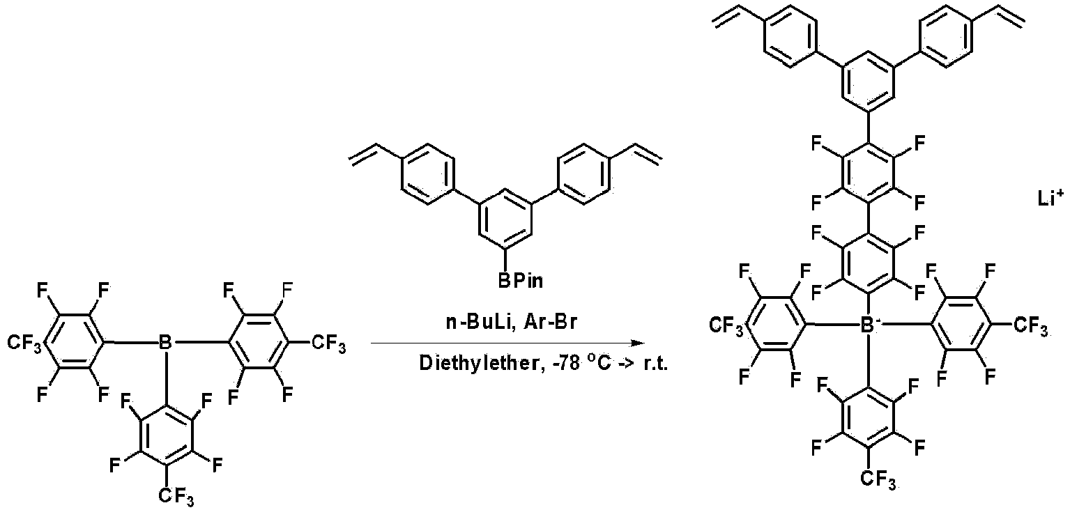
- A tris(2,3,5,6-tetrafluoro-4-(trifluoromethyl)phenyl)borane solution was prepared as in the above-described Synthesis Example 1-2.
- 4,600 mg (11.2648 mmol) of 2-(4,4"-divinyl-[1,1':3',1"-terphenyl]-5'-yl)-4,4,5,5-tetramethyl-1,3,2-dioxaborolane and 38 mL of diethyl ether were put into a flask, and the resulting mixture was stirred at -78°C for 30 minutes. 4.51 mL (11.2648 mmol, 2.5 M) of n-butyllithium was added to the flask at -78°C, and the resulting mixture was stirred for 1 hour. The solution of the flask was slowly added to the tris(2,3,5,6-tetrafluoro-4-(trifluoromethyl)phenyl)borane solution at -78°C prepared in another flask. The mixture was stirred overnight while being slowly and naturally warmed to room temperature. The reaction was terminated by adding 38 mL of water thereto, and the resulting product was extracted three times with 30 mL of dichloromethane to obtain an organic layer. The organic layer was dried and a residue was purified by column while changing an eluting solution from 50% and 100% ethyl acetate/hexane to 100% dichloromethane to obtain 8.2 g of a target compound lithium(2'',2''',3'',3''',5'',5''',6'',6'''-octafluoro-4-vinyl-5'-(4-vinylphenyl)-[1,1':3',1":4",1‴-quaterphenyl]-4‴-yl)tris(2,3,5,6-tetrafluoro-4-(trifluoromethyl)phenyl)borate.
-

- 8.2 g (6.5787 mmol) of lithium(2'',2''',3'',3''',5'',5''',6'',6'''-octafluoro-4-vinyl-5'-(4-vinylphenyl)-[1,1':3',1":4",1‴-quarterphenyl]-4'''-yl)tris(2,3,5,6-tetrafluoro-4-(trifluoromethyl)phenyl)borate, 33 mL of dichloromethane (MC) and 33 mL of water were put into a flask, and the resulting mixture was stirred for 30 minutes. 2,748 mg (6.5787 mmol) of (4-isopropylphenyl)(p-tolyl)iodonium bromide was added to the flask, and the resulting mixture was vigorously stirred for 2 hours. The resulting product was extracted three times with 30 mL of dichloromethane to obtain an organic layer, and an organic solvent was removed. A residue was purified by column sequentially with 50% and 100% ethyl acetate/hexane and 100% dichloromethane to obtain 6.7 g of Compound 3 (4-isopropylphenyl)(p-tolyl)iodonium (2'',2''',3'',3''',5'',5''',6'',6'''-octafluoro-4-vinyl-5'-(4-vinylphenyl)-[1,1':3',1":4",1‴-quarterphenyl]-4‴-yl)tris(2,3,5,6-tetrafluoro-4-(trifluoromethyl)phenyl)borate.
- A view of measuring the NMR of
Compound 3 is illustrated inFIG. 5 . - m/z: 1239.10 (100.0%), 1240.10 (59.5%), 1238.10 (24.8%), 1241.10 (17.4%), 1239.10 (14.8%), 1242.11 (3.3%), 1240.11 (2.9%), 1240.11 (1.4%)
-

- 5-Bromoisophthaldehyde (5 g, 23.4709 mmol) and CH3BrPPh3(30.75 g, 70.4126 mmol) were put into tetrahydrofuran [THF], subsequently, potassium tertbutoxide [t-BuOK] (8.0 g, 70.4126 mmol) was added thereto at 0°C, and the resulting mixture was stirred at 0°C for 1 hour. The reaction was stopped with water, and the product was extracted with ethyl acetate (EA). After magnesium sulfate (MgSO4) was added to the collected organic solution and the resulting mixture was dried and filtered, the organic solvent was removed by a vacuum rotary evaporator. A residue was purified by column to obtain 4.1 g of a target compound.
-

- 1-Bromo-3,5-divinylbenzene (4.1 g, 19.6088 mmol) was put into dioxane, potassium acetate (KOAc) (5.8 g, 58.8264 mmol) and bis(pinacolato)diboron (6.5 g, 25.4914 mmol) were additionally added thereto, and then the resulting mixture was bubbled with nitrogen at room temperature for 30 minutes. [1,1'-Bis(diphenylphosphino)ferrocene]dichloropalladium(II) (717 mg, 0.9804 mmol) was added thereto, and the resulting mixture was stirred under a condition of 80°C for 16 hours. The reaction was stopped with water, and the product was extracted with ethyl acetate. After the collected organic solution was dried by adding magnesium sulfate thereto and filtered, the organic solvent was removed by a vacuum rotary evaporator. A residue was purified by column to obtain 3.9 g of a target compound.
-

- 2-(3,5-Divinylphenyl)-4,4,5,5-tetramethyl-1,3,2-dioxaborolane (3.9 g, 15.2255 mmol) was put into 1,2-dimethoxyethane, potassium phosphate tribasic (K3PO4, 8.2 g, 38.6727 mmol) and 1,4-dibromo-2,3,5,6-tetrafluorobenzene (9.4 g, 30.4509 mmol) were additionally added thereto, and the resulting mixture was bubbled with nitrogen for 30 minutes. Tetrakis(triphenylphosphine)palladium(0) (Pd(PPh3)4, 704 mg, 0.6090 mmol) was added thereto, and the resulting mixture was stirred under a condition of 80°C for 9 hours. The reaction was stopped with water, and the product was extracted with ethyl acetate. After the collected organic solution was dried by adding magnesium sulfate thereto and filtered, the organic solvent was removed by a vacuum rotary evaporator. A residue was purified by column to obtain 3.4 g of a target compound.
-

- A tris(2,3,5,6-tetrafluoro-4-(trifluoromethyl)phenyl)borane solution was prepared as in the above-described Synthesis Example 1-2.
- 4-Bromo-2,3,5,6-tetrafluoro-3',5'-divinyl-1,1'-biphenyl (2 g, 5.5999 mmol) was put into diethyl ether, and the resulting mixture was stirred under a condition of - 78°C for 1 hour. n-Butyllithium (2.35 mL, 5.8799 mmol, 2.5 M) was slowly added thereto, and the resulting mixture was stirred under a condition of -78°C for 1 hour. The produced solution was slowly added to the prepared tris(2,3,5,6-tetrafluoro-4-(trifluoromethyl)phenyl)borane solution, and the resulting mixture was stirred overnight while being slowly warmed from -78°C to room temperature. The reaction was stopped with water, and the product was extracted with ethyl acetate. The solvent of the collected organic solution was removed by a vacuum rotary evaporator. A residue was purified by column sequentially with 50% ethyl acetate, 100% ethyl acetate, and 100% dichloromethane to obtain 3.2 g of a target compound.
-

- Lithium(2,3,5,6-tetrafluoro-3',5'-divinyl-[1,1'-biphenyl]-4-yl)tris(2,3,5,6-tetrafluoro-4-(trifluoromethyl)phenyl)borate (3.2 g, 3.3820 mmol) was put into 36 ml of a mixed solvent of dichloromethane and water (volume ratio = 1 : 1), and the resulting mixture was stirred for 30 minutes. (4-Isopropylphenyl) (p-tolyl)iodonium chloride (1260 mg, 3.3820 mmol) was added thereto, and the resulting mixture was vigorously stirred for 1 hour. The reaction was stopped with water, and the product was extracted with dichloromethane. The solvent of the collected organic solution was removed by a vacuum rotary evaporator. A residue was purified by column sequentially with 50% ethyl acetate, 100% ethyl acetate, and 100% dichloromethane to obtain 3 g of a final compound.
- A view of measuring the NMR of
Compound 4 is illustrated inFIG. 6 . - m/z: 939.04 (100.0%), 940.04 (30.3%), 938.04 (24.8%), 940.04 (9.7%), 939.05 (5.6%), 939.05 (4.3%), 941.05 (4.1%), 941.05 (3.6%), 940.05 (1.6%)
-

- A tris(2,3,5,6-tetrafluoro-4-(trifluoromethyl)phenyl)borane solution was prepared as in the above-described Synthesis Example 1-2. 5 g (27.3149 mmol) of 4-bromostyrene and 90 mL of diethyl ether were put into a flask, and the resulting mixture was stirred at - 78°C for 30 minutes. 10.9 mL (27.3149 mmol, 2.5 M) of n-butyllithium was added to the flask at -78°C, and the resulting mixture was stirred for 1 hour. The solution of the flask was slowly added to the tris(2,3,5,6-tetrafluoro-4-(trifluoromethyl)phenyl)borane solution at -78°C prepared in another flask. The mixture was stirred overnight while being slowly and naturally warmed to room temperature. The reaction was terminated by adding 90 mL of water thereto, and the resulting product was extracted three times with 90 mL of dichloromethane to obtain an organic layer. The organic layer was dried and a residue was purified by column while changing an eluting solution from 50% and 100% ethyl acetate/hexane to 100% dichloromethane to obtain 7.5 g of a target compound lithium tris(2,3,5,6-tetrafluoro-4-(trifluoromethyl)phenyl)(4-vinylphenyl)borate.
-

- 7.5 g (9.7139 mmol) of lithium tris(2,3,5,6-tetrafluoro-4-(trifluoromethyl)phenyl)(4-vinylphenyl)borate, 50 mL of dichloromethane, and 50 mL of water were put into a flask, and the resulting mixture was stirred for 30 minutes. 4,508 mg (9.7139 mmol) of (4-isopropylphenyl)(p-tolyl)iodonium bromide was added to the flask, and the resulting mixture was vigorously stirred for 2 hours. The resulting product was extracted three times with 50 mL of dichloromethane to obtain an organic layer, and an organic solvent was removed. A residue was purified by column sequentially with 50% and 100% ethyl acetate/hexane and 100% dichloromethane to obtain 7.3 g of Comparative Compound 1 ((4-isopropylphenyl)(p-tolyl)iodonium tris(2,3,5,6-tetrafluoro-4-(trifluoromethyl)phenyl)(4-vinylphenyl)borate.
-

- A tris(2,3,5,6-tetrafluoro-4-(trifluoromethyl)phenyl)borane solution was prepared as in the above-described Synthesis Example 1-2. 5 g (19.6071 mmol) of 1-bromo-2,3,5,6-tetrafluoro-4-vinylbenzene and 65 mL of diethyl ether were put into a flask, and the resulting mixture was stirred under a condition of -78°C for 30 minutes. 7.84 mL (19.6071 mmol, 2.5 M) of n-butyllithium was added to the flask at -78°C, and the resulting mixture was stirred for 1 hour. The solution of the flask was slowly added to the tris(2,3,5,6-tetrafluoro-4-(trifluoromethyl)phenyl)borane solution at -78°C prepared in another flask. The mixture was stirred overnight while being slowly and naturally warmed to room temperature. The reaction was terminated by adding 60 mL of water thereto, and the resulting product was extracted three times with 60 mL of dichloromethane to obtain an organic layer. The organic layer was dried and a residue was purified by column while changing an eluting solution from 50% and 100% ethyl acetate/hexane to 100% dichloromethane to obtain 10 g of a target compound lithium tris(2,3,5,6-tetrafluoro-4-(trifluoromethyl)phenyl)(2,3,5,6-tetrafluoro-4-vinylphenyl)borate).
-

- 10 g (8.6488 mmol) of lithium tris(2,3,5,6-tetrafluoro-4-(trifluoromethyl)phenyl)(2,3,5,6-tetrafluoro-4-vinylphenyl)borate, 43 mL of dichloromethane, and 43 mL of water were put into a flask, and the resulting mixture was stirred for 30 minutes. 3,613 mg (8.6488 mmol) of (4-isopropylphenyl)(p-tolyl)iodonium bromide was added to the flask, and the resulting mixture was vigorously stirred for 2 hours. The resulting product was extracted three times with 40 mL of dichloromethane to obtain an organic layer, and an organic solvent was removed. A residue was purified by column sequentially with 50% and 100% ethyl acetate/hexane and 100% dichloromethane to obtain 6.5 g of Comparative Compound 2 (4-isopropylphenyl)(p-tolyl)iodonium tris(2,3,5,6-tetrafluoro-4-(trifluoromethyl)phenyl)(2,3,5,6-tetrafluoro-4-vinylphenyl) borate.
-

- A tris(2,3,5,6-tetrafluoro-4-(trifluoromethyl)phenyl)borane solution was prepared as in the above-described Synthesis Example 1-2. 5 g (15.1007 mmol) of 3-(4-bromo-2,3,5,6-tetrafluorophenyl)bicyclo[4.2.0]octa-1,3,5-triene and 50 mL of diethyl ether were put into a flask, and the resulting mixture was stirred at -78°C for 30 minutes. 6.04 mL (15.1007 mmol, 2.5 M) of n-butyllithium was added to the flask at -78°C, and the resulting mixture was stirred for 1 hour. The solution of the flask was slowly added to the tris(2,3,5,6-tetrafluoro-4-(trifluoromethyl)phenyl)borane solution at -78°C prepared in another flask. The mixture was stirred overnight while being slowly and naturally warmed to room temperature. The reaction was terminated by adding 50 mL of water thereto, and the resulting product was extracted three times with 50 mL of dichloromethane to obtain an organic layer. The organic layer was dried and a residue was purified by column while changing an eluting solution from 50% and 100% ethyl acetate/hexane to 100% dichloromethane to obtain 9.8 g of a target compound lithium (4-(bicyclo[4.2.0]octa-1,3,5-trien-3-yl)-2,3,5,6-tetrafluorophenyl)tris(2,3,5,6-tetrafluoro-4-(trifluoromethyl)phenyl)borate.
-

- 9.8 g (10.6504 mmol) of lithium (4-(bicyclo[4.2.0]octa-1,3,5-trien-3-yl)-2,3,5,6-tetrafluorophenyl)tris(2,3,5,6-tetrafluoro-4-(trifluoromethyl)phenyl)borate, 50 mL of dichloromethane and 50 mL of water were put into a flask, and the resulting mixture was stirred for 30 minutes. 4,449 mg (10.6504 mmol) of (4-isopropylphenyl)(p-tolyl)iodonium bromide was added to the flask, and the resulting mixture was vigorously stirred for 2 hours. The resulting product was extracted three times with 50 mL of dichloromethane to obtain an organic layer, and an organic solvent was removed. A residue was purified by column sequentially with 50% and 100% ethyl acetate/hexane and 100% dichloromethane to obtain 7.2 g of Comparative Compound 3 (4-isopropylphenyl)(p-tolyl)iodonium(4-(bicyclo[4.2.0]octa-1,3,5-trien-3-yl)-2,3,5,6-tetrfluorophenyl)tris(2,3,5,6-tetrafluoro-4-(trifluoromethyl)phenyl)borate.
-

- 10 g (30.2014 mmol) of 4-bromo-2,3,5,6-tetrafluoro-4'-vinyl-1,1'-biphenyl and 100 mL of diethyl ether were put into a flask, and the resulting mixture was stirred under a condition of -78°C for 30 minutes. 12.08 mL (30.2014 mmol) of n-butyllithium was slowly added to the flask, and the resulting mixture was stirred under a condition of -78°C for 1 hour. 6.95 mL (6.9463 mmol, 1 M) of boron trichloride was slowly added thereto, and the resulting mixture was stirred overnight while being slowly warmed from -78°C to room temperature. 100 mL of water was added to the flask, and the resulting product was extracted three times with 100 mL of ethyl acetate to obtain an organic layer. The organic layer was removed and a residue was purified by column while changing an eluting solution from 50% and 100% ethyl acetate/hexane to 100% dichloromethane to obtain 6.3 g of a target compound lithium tetrakis(2,3,5,6-tetrafluoro-4'-vinyl-[1,1'-biphenyl]-4-yl)borate.
-

- 6.3 g (6.1610 mmol) of lithium tetrakis(2,3,5,6-tetrafluoro-4'-vinyl-[1,1'-biphenyl]-4-yl)borate, 30 mL of dichloromethane, and 30 mL of water were put into a flask, and the resulting mixture was stirred for 30 minutes. 2,574 mg (6.1610 mmol) of (4-isopropylphenyl) (p-tolyl)iodonium bromide was added to the flask, and the resulting mixture was vigorously stirred for 2 hours. The resulting product was extracted three times with 30 mL of dichloromethane to obtain an organic layer, and an organic solvent was removed. A residue was purified by column sequentially with 50% and 100% ethyl acetate/hexane and 100% dichloromethane to obtain 7.2 g of Comparative Compound 4 (4-isopropylphenyl) (p-tolyl)iodonium tetrakis(2,3,5,6-tetrafluoro-4'-vinyl-[1,1'-biphenyl]-4-yl)borate.
-


- After Chemical Formula A-A (9 g, 27.9mmol) and 4-formylbenzene boric acid (4.18 g, 27.9 mmol) were dissolved in anhydrous tetrahydrofuran (THF) (100 mL), Pd(PPh3)4 (0.32 g, 0.28 mmol) and 70 ml of a 2 M potassium carbonate (K2CO3 /H2O) aqueous solution were added thereto, and the resulting mixture was refluxed for 6 hours. After the reaction solution was cooled to room temperature, the organic layer was extracted. The reaction solution was concentrated and recrystallized with ethyl alcohol (EtOH) to obtain Chemical Formula A-B (8.9 g, yield 92%). MS: [M+H]+ = 348
- Chemical Formula A-B (8.2 g, 23.6 mmol) prepared in Step 1) was dissolved in chloroform (200 mL), N-bromosuccinimide (4.15 g, 23.6 mmol) was added thereto, and then the resulting mixture was stirred at room temperature for 5 hours. Distilled water was put into the reaction solution, the reaction was terminated, and the organic layer was extracted. The reaction solution was concentrated and recrystallized with ethyl alcohol (EtOH) to obtain Chemical Formula A-C (8.25 g, yield 82%). MS: [M+H]+ = 427
-
FIG. 8 is a view illustrating an MS spectrum of Chemical Formula A-C. - After dihydroxyethene (1.1 g, 17.7 mmol) was dissolved in 50 ml of toluene in Chemical Formula A-C (3.1 g, 8.85 mmol) prepared in Step 2), the resulting solution was stirred at 150°C for 48 hours. After ethanol was added to the reaction solution, a precipitate was formed. A formed ivory solid was filtered, washed with ethanol, and then dried under vacuum to obtain Chemical Formula A-D (2.8 g, yield 80.2%). MS: [M+H]+ = 469
- Chemical Formula A-D (3 g, 7.04 mmol) prepared in Step 3) and N4,N4'-diphenyl-[1,1'-biphenyl]-4,4'-diamine (0.99 g, 2.93 mmol) were dissolved in 40 ml of xylene, sodium-tertiary-butoxide (0.68 g , 7.04 mmol), 0.13 g (0.23 mmol) of bis(dibenzylideneacetone)palladium(0), and 0.11 ml (0.23 mmol) of a 50 wt% tri-tertiary-butylphosphine toluene solution were added thereto, and then the resulting mixture was refluxed under nitrogen flow for 5 hours.
- Distilled water was put into the reaction solution, the reaction was terminated, and the organic layer was extracted. After column separation was performed with a normal-hexane/tetrahydrofuran = 6/1 solvent, the resulting product was stirred in ethyl acetate (EtOH), filtered, and then dried under vacuum to obtain Chemical Formula A-E (2.92 g, yield 48 %). MS: [M+H]+ = 1027
- After (bromomethyl)triphenylphosphonium bromide (2.55 g, 5.85 mmol) was dissolved in 100 mL of tetrahydrofuran (THF), 1 eq. of n-butyllithium (n-BuLi)(2.5M in HEX, 2.34 mL, 5.85 mmol) was added thereto at -78°C, and the resulting mixture was stirred for 20 minutes. After the reaction temperature was increased to 0°C, Chemical Formula A-E (2 g, 1.95 mmol) prepared in Step 4) was added to the reactant, and the resulting mixture was stirred at the same temperature for 1 hour. Distilled water was put into the reaction solution, the reaction was terminated, and the organic layer was extracted. The reaction solution was concentrated, dissolved in methylene chloride (MC), and then recrystallized with ethyl alcohol (EtOH) to obtain Chemical Formula A (1.28 g, yield 64%). MS: [M+H]+ = 1023
-
FIG. 9 is a view illustrating an MS spectrum of Chemical Formula A. -

- 5-Bromoisophthaldehyde (5 g, 23.4709 mmol) and CH3BrPPh3(30.75 g, 70.4126 mmol) were put into tetrahydrofuran [THF], subsequently, potassium tertbutoxide [t-BuOK] (8.0 g, 70.4126 mmol) was added thereto at 0°C, and the resulting mixture was stirred at 0°C for 1 hour. The reaction was stopped with water, and the product was extracted with ethyl acetate (EA). After magnesium sulfate (MgSO4) was added to the collected organic solution and the resulting mixture was dried and filtered, the organic solvent was removed by a vacuum rotary evaporator. A residue was purified by column to obtain 4.1 g of a target compound.
-

- 1-Bromo-3,5-divinylbenzene (4.1 g, 19.6088 mmol) was put into dioxane, potassium acetate (KOAc) (5.8 g, 58.8264 mmol) and bis(pinacolato)diboron (6.5 g, 25.4914 mmol) were additionally added thereto, and then the resulting mixture was bubbled with nitrogen at room temperature for 30 minutes. [1,1'-Bis(diphenylphosphino)ferrocene]dichloropalladium(II) (717 mg, 0.9804 mmol) was added thereto, and the resulting mixture was stirred under a condition of 80°C for 16 hours. The reaction was stopped with water, and the product was extracted with ethyl acetate. After the collected organic solution was dried by adding magnesium sulfate thereto and filtered, the organic solvent was removed by a vacuum rotary evaporator. A residue was purified by column to obtain 3.9 g of a target compound.
-

- 2-(3,5-Divinylphenyl)-4,4,5,5-tetramethyl-1,3,2-dioxaborolane (3.9 g, 15.2255 mmol) was put into 1,2-dimethoxyethane, potassium phosphate tribasic (K3PO4, 8.2 g, 38.6727 mmol) and 4,4'-dibromo-2,2',3,3',5,5',6,6'-octafluoro-1,1'-biphenyl (13.883 g, 30.4509 mmol) were additionally added thereto, and the resulting mixture was bubbled with nitrogen for 30 minutes. Tetrakis(triphenylphosphine)palladium(0) (704 mg, 0.6090 mmol) was added thereto, and the resulting mixture was stirred under a condition of 80°C for 9 hours. The reaction was stopped with water, and the product was extracted with ethyl acetate. After the collected organic solution was dried by adding magnesium sulfate thereto and filtered, the organic solvent was removed by a vacuum rotary evaporator. A residue was purified by column to obtain 4.1 g of 4-bromo-2,2',3,3',5,5',6,6'-octafluoro-3",5"-divinyl-1,1':4',1"-terphenyl.
-

- A tris(2,3,5,6-tetrafluoro-4-(trifluoromethyl)phenyl)borane solution was prepared as in the above-described Synthesis Example 1-2.
- 4-Bromo-2, 2' , 3, 3' , 5, 5' , 6, 6' -octafluoro-3 " , 5"-divinyl-1,1':4',1'-terphenyl (2.829 g, 5.5999 mmol) was put into diethyl ether, and the resulting mixture was stirred under a condition of -78°C for 1 hour. n-Butyllithium (2.35 mL, 5.8799 mmol, 2.5 M) was slowly added thereto, and the resulting mixture was stirred under a condition of -78°C for 1 hour. The produced solution was slowly added to the prepared tris(2,3,5,6-tetrafluoro-4-(trifluoromethyl)phenyl)borane solution, and the resulting mixture was stirred overnight while being slowly warmed from -78°C to room temperature. The reaction was stopped with water, and the product was extracted with ethyl acetate. The solvent of the collected organic solution was removed by a vacuum rotary evaporator. A residue was purified by column sequentially with 50% ethyl acetate, 100% ethyl acetate, and 100% dichloromethane to obtain 3.0 g of a target compound.
-

- Lithium (2,2',3,3',5,5',6,6'-octafluoro-3",5"-divinyl-[1,1':4',1"-terphenyl]-4-yl)tris(2,3,5,6-tetrafluoro-4-(trifluoromethyl)phenyl)borate (3.0 g, 2.7416 mmol) was put into 36 ml of a mixed solvent of dichloromethane and water (volume ratio = 1 : 1), and the resulting mixture was stirred for 30 minutes. (4-Isopropylphenyl)(p-tolyl)iodonium chloride (1022 mg, 2.7416 mmol) was added thereto, and the resulting mixture was vigorously stirred for 1 hour. The reaction was stopped with water, and the product was extracted with dichloromethane. The solvent of the collected organic solution was removed by a vacuum rotary evaporator. A residue was purified by column sequentially with 50% ethyl acetate, 100% ethyl acetate, and 100% dichloromethane to obtain 3.4 g of [Compound 5].
- A view of measuring the NMR of
Compound 5 is illustrated inFIG. 10 . - m/z: 1424.08 (100.0%), 1425.08 (63.8%), 1423.08 (24.8%), 1426.09 (17.1%), 1424.09 (15.9%), 1427.09 (4.1%), 1425.09 (3.3%), 1426.09 (2.9%), 1425.09 (1.7%), 1426.09 (1.0%)
-

- (E)-1-bromo-4-(prop-1-en-1-yl)benzene (5.0 g, 25.3704 mmol) was put into dioxane, potassium acetate (KOAc) (7.47 g, 76.1112 mmol) and bis(pinacolato)diboron (8.38 g, 32.9815 mmol) were additionally added thereto, and then the resulting mixture was bubbled with nitrogen at room temperature for 30 minutes. [1,1'-Bis(diphenylphosphino)ferrocene]dichloropalladium(II) (1035 mg, 1.2685 mmol) was added thereto, and the resulting mixture was stirred under a condition of 80°C for 16 hours. The reaction was stopped with water, and the product was extracted with ethyl acetate. After the collected organic solution was dried by adding magnesium sulfate thereto and filtered, the organic solvent was removed by a vacuum rotary evaporator. A residue was purified by column to obtain 4.5 g of a target compound.
-

- (E)-4,4,5,5-tetramethyl-2-(4-(prop-1-en-1-yl)phenyl)-1,3,2-dioxaborolane (4.5 g, 18.4320 mmol) was put into 1,2-dimethoxyethane, potassium phosphate tribasic (K3PO4, 9.9 g, 46.8174 mmol) and 4,4'-dibromo-2,2',3,3',5,5',6,6'-octafluoro-1,1'-biphenyl (16.807 g, 36.8640 mmol) were additionally added thereto, and the resulting mixture was bubbled with nitrogen for 30 minutes. Tetrakis(triphenylphosphine)palladium(0) (852 mg, 0.7373 mmol) was added thereto, and the resulting mixture was stirred under a condition of 80°C for 9 hours. The reaction was stopped with water, and the product was extracted with ethyl acetate. After the collected organic solution was dried by adding magnesium sulfate thereto and filtered, the organic solvent was removed by a vacuum rotary evaporator. A residue was purified by column to obtain 5.6 g of (E)-4-bromo-2,2',3,3',5,5',6,6'-octafluoro-4"-(prop-1-en-1-yl)-1,1':4',1"-terphenyl.
-

- A tris(2,3,5,6-tetrafluoro-4-(trifluoromethyl)phenyl)borane solution was prepared as in the above-described Synthesis Example 1-2.
- (E)-4-bromo-2,2',3,3',5,5',6,6'-octafluoro-4''-(prop-1-en-1-yl)-1,1':4',1"-terphenyl (5.6 g, 11.3547 mmol) was put into diethyl ether, and the resulting mixture was stirred under a condition of -78°C for 1 hour. n-Butyllithium (4.77 mL, 11.9224 mmol, 2.5 M) was slowly added thereto, and the resulting mixture was stirred under a condition of -78°C for 1 hour. The produced solution was slowly added to the prepared tris(2,3,5,6-tetrafluoro-4-(trifluoromethyl)phenyl)borane solution, and the resulting mixture was stirred overnight while being slowly warmed from -78°C to room temperature. The reaction was stopped with water, and the product was extracted with ethyl acetate. The solvent of the collected organic solution was removed by a vacuum rotary evaporator. A residue was purified by column sequentially with 50% ethyl acetate, 100% ethyl acetate, and 100% dichloromethane to obtain 7.4 g of a target compound.
-

- Lithium (E)-(2,2',3,3',5,5',6,6'-octafluoro-4''-(prop-1-en-1-yl)-[1,1':4',1"-terphenyl]-4-yl)tris(2,3,5,6-tetrafluoro-4-(trifluoromethyl)phenyl)borate (7.4 g, 6.8377 mmol) was put into 36 ml of a mixed solvent of dichloromethane (MC) and water (volume ratio = 1 : 1), and the resulting mixture was stirred for 30 minutes. (4-Isopropylphenyl)(p-tolyl)iodonium chloride (2548 mg, 6.8377 mmol) was added thereto, and the resulting mixture was vigorously stirred for 1 hour. The reaction was stopped with water, and the product was extracted with dichloromethane. The solvent of the collected organic solution was removed by a vacuum rotary evaporator. A residue was purified by column sequentially with 50% ethyl acetate, 100% ethyl acetate, and 100% dichloromethane to obtain 5.4 g of [Compound 6].
- A view of measuring the NMR of
Compound 6 is illustrated inFIG. 11 . - m/z: 1412.08 (100.0%), 1413.08 (62.7%), 1411.08 (24.8%), 1414.09 (16.5%), 1412.09 (15.6%), 1415.09 (3.9%), 1413.09 (3.2%), 1414.09 (2.8%), 1413.09 (1.6%)
- As a coating composition, a coating composition was mixed as described in the following Table 1, and specifically,
Coating Composition 1 was produced by mixing a p-doping material represented by the followingCompound 1 of the present disclosure and a host compound [Compound A] and cyclohexanone. In this case, the coating composition was produced by mixingCompound 1, Compound A and the organic solvent at a weight ratio of 2 : 8 : 490. - A coating layer was formed by spin-
coating Coating Composition 1, and the film was fired at 250°C or less. -
Coating Composition 2 was produced in the same manner as inCoating Composition 1, except thatCompound 2 was used instead ofCompound 1 of the present disclosure, a coating layer was formed by spin-coating Coating Composition 2, and the film was fired at 250°C or less. -
Coating Composition 3 was produced in the same manner as inCoating Composition 1, except thatCompound 3 was used instead ofCompound 1 of the present disclosure, a coating layer was formed by spin-coating Coating Composition 3, and the film was fired at 250°C or less. -
Coating Composition 4 was produced in the same manner as inCoating Composition 1, except thatCompound 4 was used instead ofCompound 1 of the present disclosure, a coating layer was formed by spin-coating Coating Composition 4, and the film was fired at 250°C or less. -
Coating Composition 5 was produced in the same manner as inCoating Composition 1, except thatCompound 5 was used instead ofCompound 1 of the present disclosure, a coating layer was formed by spin-coating Coating Composition 5, and the film was fired at 250°C or less. -
Coating Composition 6 was produced in the same manner as inCoating Composition 1, except thatComparative Compound 1 was used instead ofCompound 1 of the present disclosure, a coating layer was formed by spin-coating Coating Composition 5, and the film was fired at 250°C or less. -
Coating Composition 7 was produced in the same manner as inCoating Composition 1, except thatComparative Compound 2 was used instead ofCompound 1 of the present disclosure, a coating layer was formed by spin-coating Coating Composition 7, and the film was fired at 250°C or less. -
Coating Composition 8 was produced in the same manner as inCoating Composition 1, except thatComparative Compound 3 was used instead ofCompound 1 of the present disclosure, a coating layer was formed by spin-coating Coating Composition 8, and the film was fired at 250°C or less. -
Coating Composition 9 was produced in the same manner as inCoating Composition 1, except thatComparative Compound 4 was used instead ofCompound 1 of the present disclosure, a coating layer was formed by spin-coating Coating Composition 9, and the film was fired at 250°C or less. -
Coating Composition 10 was produced in the same manner as inCoating Composition 1, except thatCompound 6 was used instead ofCompound 1 of the present disclosure, a coating layer was formed by spin-coating Coating Composition 10, and the film was fired at 250°C or less.
- Coating Composition 11 was produced in the same manner as in
Coating Composition 1, except thatCompound 7 was used instead ofCompound 1 of the present disclosure, a coating layer was formed by spin-coating Coating Composition 11, and the film was fired at 250°C or less.
- Coating Composition 12 was produced in the same manner as in
Coating Composition 1, except thatCompound 8 was used instead ofCompound 1 of the present disclosure, a coating layer was formed by spin-coating Coating Composition 12, and the film was fired at 250°C or less.[Table 1] Coating Composition Host p-doping material Spin speed (rpm) /Time (s) Firing temperature (°C) /Time (min) 1 Compound A Compound 1 1000/60 230/30 2 Compound A Compound 2 1000/60 230/30 3 Compound A Compound 3 1000/60 230/30 4 Compound A Compound 4 1000/60 230/30 5 Compound A Compound 5 1000/60 230/30 6 Compound A Comparative Compound 11000/60 230/30 7 Compound A Comparative Compound 21000/60 230/30 8 Compound A Comparative Compound 31000/60 230/30 9 Compound A Comparative Compound 41000/60 230/30 10 Compound A Compound 6 1000/60 230/30 11 Compound A Compound 7 1000/60 230/30 12 Compound A Compound 8 1000/60 230/30 - Through Examples 1 to 8 and Comparative Examples 1 to 4, it was confirmed that a film was formed.
- In order to confirm the film retention rates of
Compound 1,Compound 3,Compound 5,Compound 6,Compound 7,Compound 8 andComparative Compounds 1 to 4, the UV-vis absorption spectrum of the film formed by the following method was measured. - For the film retention rate, the solvent resistances of
Compound 1,Compound 3,Compound 5,Compound 6,Compound 7,Compound 8 andComparative Compounds 1 to 4 were evaluated using cyclohexanone. Specifically, a solution, in which 4 wt% of each ofCompound 1,Compound 3,Compound 5,Compound 6,Compound 7,Compound 8 andComparative Compounds 1 to 4 prepared above was dissolved in cyclohexanone, was prepared, and then a quartz substrate was spin-coated with the solution to have a thickness of 100 nm. Thereafter, after the substrate was heat-treated at a temperature of 190°C to 200°C in a nitrogen atmosphere for 30 minutes, the UV-vis absorption spectrum was measured. Subsequently, the same sample was immersed in cyclohexanone for 10 minutes and remove, the solvent was dried from the sample, and then the UV-vis absorption spectrum was also measured. - In this case, the UV-vis absorption spectra for
Compound 1 andComparative Compounds 1 to 4 after immersion in the solvent, which are capable of confirming the film retention rates, are illustrated inFIG. 7 , and the absorbances at 350 nm, which is the maximum absorption wavelength forCompound 1,Compound 3,Compound 5,Compound 6,Compound 7,Compound 8 andComparative Compounds 1 to 4, are compared in the following Table 2.[Table 2] Classification p-doping material Absorbance @ 350nm Example 1 Compound 10.802 Example 3 Compound 30.813 Example 5 Compound 50.801 Comparative Example 1 Comparative Compound 10.483 Comparative Example 2 Comparative Compound 20.526 Comparative Example 3 Comparative Compound 30.392 Comparative Example 4 Comparative Compound 40.467 Example 6 Compound 60.524 Example 7 Compound 70.603 Example 8 Compound 80.546 - In the process of manufacturing the device, the film is retained while being cured during the heat treatment. The higher absorbance means that a relatively more residue remains on the film. Through
FIG. 7 and Table 2, it could be confirmed that in the case of Comparative Examples 1 to 4 where the comparative compounds were used, the absorbance was relatively low because the film was not retained compared to Example 1 whereCompound 1 was used and there was a portion which was washed off. - Solubilities were confirmed by dissolving
Compounds 1 to 3,Compound 5 andComparative Compound 4 synthesized as p-doping materials at a weight ratio of 5 wt% relative to each solvent shown in the following Table 3.[Table 3] Solvent Toluene Dichloromet hane Acetone Compound 1 Dissolved Dissolved Dissolved Compound 2Dissolved Dissolved Dissolved Compound 3Dissolved Dissolved Dissolved Compound 5Dissolved Dissolved Dissolved Comparative Insoluble Dissolved Dissolved Compound 4 - Through the experimental results, it can be confirmed that the compound of the present specification having asymmetry compared to
Comparative Compound 4 has a property of being dissolved relatively well in a non-polar solvent. In a solution process organic light emitting device, when an ink solvent is selected for the process, the ink solvent needs to dissolve both a host and a dopant. In this regard, the solubility of the dopant is important, and the compound of the present specification has solubility for a wider variety of solvents, and thus has an advantage in that a wider variety of solvents can be selected.
Claims (17)
- A compound represented by the following Chemical Formula 1:
 in Chemical Formula 1,R1 to R19 are the same as or different from each other, and are each independently hydrogen, deuterium, a fluoro group, a fluoroalkyl group, a cyano group, or a substituted or unsubstituted alkyl group,Ar is a substituted or unsubstituted (n1+1)-valent aryl group,X is a curing group,m1 is an integer from 1 to 3, and when m1 is 2 or higher, two or more substituents in the parenthesis are the same as or different from each other, andn1 is an integer from 1 to 5, and when n1 is 2 or higher, two or more substituents in the parenthesis are the same as or different from each other.
 - The compound of claim 1, wherein the curing group is any one of the following Chemical Formulae 7-1 to 7-5:





 in Chemical Formulae 7-1 to 7-5,L1 is a direct bond; O; S; a substituted or unsubstituted (c+1)-valent alkyl group; a substituted or unsubstituted (c+1)-valent aryl group; or a substituted or unsubstituted (c+1)-valent heterocyclic group,L2 to L5 are the same as or different from each other, and are each independently a direct bond; O; S; a substituted or unsubstituted alkylene group; a substituted or unsubstituted arylene group; or a substituted or unsubstituted divalent heterocyclic group,L6 is O or a substituted or unsubstituted alkylene group,R200 to R202 and R209 to R211 are the same as or different from each other, and are each independently hydrogen, deuterium, a halogen group or a substituted or unsubstituted alkyl group,R203 is a substituted or unsubstituted alkyl group,R204 to R207 are the same as or different from each other, and are each independently hydrogen, deuterium, or a substituted or unsubstituted alkyl group,R208 is a substituted or unsubstituted alkyl group or a substituted or unsubstituted aryl group,c is an integer of 1 or 2, and when c is 2, structures in the parenthesis are the same as or different from each other,k1 to k5 are each an integer from 1 to 4,when k1 is 2 or higher, L1's are the same as or different from each other,when k2 is 2 or higher, L2's are the same as or different from each other,when k3 is 2 or higher, L3's are the same as or different from each other,when k4 is 2 or higher, L4's are the same as or different from each other, andwhen k5 is 2 or higher, L5's are the same as or different from each other.
 - The compound of claim 1, wherein X is a substituted or unsubstituted alkenyl group; or an aryl group which is substituted with a substituted or unsubstituted alkenyl group.
- The compound of claim 1, wherein Chemical Formula 1 is represented by the following Chemical Formula 2 or 3:


 in Chemical Formulae 2 and 3,R1 to R15, Ar, X and n1 are the same as those defined in Chemical Formula 1, andR21 to R28 are the same as or different from each other, and are each independently hydrogen, deuterium, a fluoro group, a fluoroalkyl group, a cyano group, or a substituted or unsubstituted alkyl group.
 - The compound of claim 1, wherein Ar is a substituted or unsubstituted (n1+1)-valent aryl group having 6 to 30 carbon atoms.
- The compound of claim 1, wherein Chemical Formula 1 is represented by the following Chemical Formula 4:
 in Chemical Formula 4,R1 to R19, X, n1 and m1 are the same as those defined in Chemical Formula 1,R101 is hydrogen; deuterium; a halogen group; a substituted or unsubstituted alkyl group; a substituted or unsubstituted alkoxy group; a substituted or unsubstituted aryl group; or a substituted or unsubstituted heteroaryl group, andn2 is an integer from 0 to 4, and when n2 is 2 or higher, two or more R101's are the same as or different from each other, and n1+n2 is 1 to 5.
 - The compound of claim 1, wherein Chemical Formula 1 is represented by the following Chemical Formula 5 or 6:


 in Chemical Formulae 5 and 6,R1 to R15, X and n1 are the same as those defined in Chemical Formula 1,R21 to R28 are the same as or different from each other, and are each independently hydrogen, deuterium, a fluoro group, a fluoroalkyl group, a cyano group, or a substituted or unsubstituted alkyl group,R101 is hydrogen; deuterium; a halogen group; a substituted or unsubstituted alkyl group; a substituted or unsubstituted alkoxy group; a substituted or unsubstituted aryl group; or a substituted or unsubstituted heteroaryl group, andn2 is an integer from 0 to 4, and when n2 is 2 or higher, two or more R101's are the same as or different from each other, and n1+n2 is 1 to 5.
 - The compound of claim 1, wherein X is selected from the following structures:
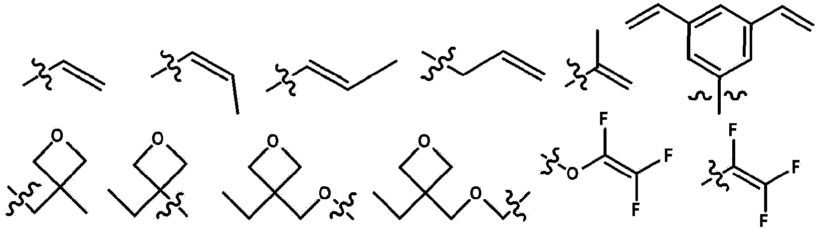


- The compound of claim 1, wherein X is a vinyl group; or an aryl group which is substituted with a vinyl group.
- The compound of claim 1, wherein R1 to R19 are the same as or different from each other, and are each independently a fluoro group or a fluoroalkyl group.
- The compound of claim 1, further comprising a counterion.
- The compound of claim 1, wherein Chemical Formula 1 is represented by any one of the following compounds:


- A coating composition comprising the compound of any one of claims 1 to 12.
- An organic light emitting device comprising:a first electrode;a second electrode; andan organic material layer having one or more layers provided between the first electrode and the second electrode,wherein one or more layers of the organic material layer comprise the coating composition of claim 13 or a cured product thereof.
- The organic light emitting device of claim 14, wherein the organic material layer comprising the coating composition or the cured product thereof is a hole transport layer or a hole injection layer.
- A method of manufacturing an organic light emitting device, the method comprising:preparing a substrate;forming a first electrode on the substrate;forming an organic material layer having one or more layers on the first electrode; andforming a second electrode on the organic material layer,wherein the forming of the organic material layer comprises forming an organic material layer having one or more layers by using the coating composition of claim 13.
- The method of claim 16, wherein the forming of the organic material layer having one or more layers by using the coating composition comprises:coating the coating composition on the first electrode; andheat-treating or light-treating the coated coating composition.
Applications Claiming Priority (2)
| Application Number | Priority Date | Filing Date | Title |
|---|---|---|---|
| KR20210038765 | 2021-03-25 | ||
| PCT/KR2022/004232 WO2022203454A1 (en) | 2021-03-25 | 2022-03-25 | Compound, coating composition comprising same, organic light-emitting device using same, and manufacturing method therefor |
Publications (3)
| Publication Number | Publication Date |
|---|---|
| EP4253389A1 true EP4253389A1 (en) | 2023-10-04 |
| EP4253389A4 EP4253389A4 (en) | 2024-07-10 |
| EP4253389B1 EP4253389B1 (en) | 2025-11-26 |
Family
ID=83397623
Family Applications (1)
| Application Number | Title | Priority Date | Filing Date |
|---|---|---|---|
| EP22776154.1A Active EP4253389B1 (en) | 2021-03-25 | 2022-03-25 | Compound, coating composition comprising same, organic light-emitting device using same, and manufacturing method therefor |
Country Status (6)
| Country | Link |
|---|---|
| US (1) | US20240279249A1 (en) |
| EP (1) | EP4253389B1 (en) |
| JP (1) | JP7712023B2 (en) |
| KR (1) | KR20220133814A (en) |
| CN (1) | CN116636328A (en) |
| WO (1) | WO2022203454A1 (en) |
Families Citing this family (2)
| Publication number | Priority date | Publication date | Assignee | Title |
|---|---|---|---|---|
| JPWO2024204045A1 (en) * | 2023-03-28 | 2024-10-03 | ||
| CN117327051B (en) * | 2023-08-31 | 2026-02-10 | 上海理工大学 | A carbazole-based fluorescent molecule for rapid and selective detection of multiple trace ions, its preparation method and application. |
Family Cites Families (11)
| Publication number | Priority date | Publication date | Assignee | Title |
|---|---|---|---|---|
| JPH08127611A (en) * | 1994-11-01 | 1996-05-21 | Showa Denko Kk | Compound containing boron |
| JPH11286491A (en) * | 1998-03-31 | 1999-10-19 | Idemitsu Petrochem Co Ltd | Ionic compound, catalyst for polymerizing olefin, and production of olefin-based polymer |
| US6184171B1 (en) * | 1998-10-05 | 2001-02-06 | W.R. Grace & Co. -Conn | Supported bidentate and tridentate catalyst compositions and olefin polymerization using same |
| JP2000178281A (en) * | 1998-12-18 | 2000-06-27 | Idemitsu Petrochem Co Ltd | Production of ionic compound, olefin polymerization catalyst and olefin-based polymer |
| JP2016204636A (en) * | 2015-04-09 | 2016-12-08 | 三洋化成工業株式会社 | Zwitterion type borate salt and curable resin composition containing the same |
| JP6380694B2 (en) * | 2016-03-24 | 2018-08-29 | 三菱ケミカル株式会社 | Electron-accepting compound, charge transport film composition, and light-emitting device using the same |
| TW201829731A (en) | 2016-11-04 | 2018-08-16 | 美商陶氏全球科技責任有限公司 | Composition containing ammonium radical cation |
| WO2018097659A1 (en) * | 2016-11-25 | 2018-05-31 | 주식회사 엘지화학 | Ionic compound, coating composition comprising same, and organic light-emitting diode |
| JP7310605B2 (en) * | 2017-09-22 | 2023-07-19 | 三菱ケミカル株式会社 | Charge-transporting compound, composition containing charge-transporting compound, and organic electroluminescence device using said composition |
| JP7275738B2 (en) * | 2018-09-21 | 2023-05-18 | 三菱ケミカル株式会社 | Composition, charge transport film and organic electroluminescence device |
| KR102702294B1 (en) | 2019-09-30 | 2024-09-04 | 삼성디스플레이 주식회사 | Display apparatus, method of driving display panel using the same |
-
2022
- 2022-03-25 KR KR1020220037339A patent/KR20220133814A/en active Pending
- 2022-03-25 CN CN202280008105.4A patent/CN116636328A/en active Pending
- 2022-03-25 JP JP2023539360A patent/JP7712023B2/en active Active
- 2022-03-25 EP EP22776154.1A patent/EP4253389B1/en active Active
- 2022-03-25 US US18/271,352 patent/US20240279249A1/en active Pending
- 2022-03-25 WO PCT/KR2022/004232 patent/WO2022203454A1/en not_active Ceased
Also Published As
| Publication number | Publication date |
|---|---|
| KR20220133814A (en) | 2022-10-05 |
| EP4253389A4 (en) | 2024-07-10 |
| US20240279249A1 (en) | 2024-08-22 |
| JP2024501990A (en) | 2024-01-17 |
| EP4253389B1 (en) | 2025-11-26 |
| CN116636328A (en) | 2023-08-22 |
| WO2022203454A1 (en) | 2022-09-29 |
| JP7712023B2 (en) | 2025-07-23 |
Similar Documents
| Publication | Publication Date | Title |
|---|---|---|
| EP3767694B1 (en) | Organic light-emitting device | |
| EP3767695B1 (en) | Organic light-emitting device | |
| EP4074689A1 (en) | Compound, coating composition comprising same, organic light-emitting device using same, and manufacturing method therefor | |
| EP4180416B1 (en) | Novel compound, coating composition comprising same, organic light-emitting device using same, and manufacturing method therefor | |
| JP7558612B2 (en) | Polymer and organic light-emitting device using same | |
| CN110291067B (en) | Compound, coating composition containing same, organic light-emitting device using same, and manufacturing method thereof | |
| EP4186892B1 (en) | Novel compound, coating composition comprising same, organic light-emitting device using same, and manufacturing method therefor | |
| EP4253389B1 (en) | Compound, coating composition comprising same, organic light-emitting device using same, and manufacturing method therefor | |
| KR102885077B1 (en) | Polymer and organic light emitting device using the same | |
| EP4403554B1 (en) | Compound, coating composition comprising same, organic light-emitting device using same, and manufacturing method therefor | |
| EP4368652B1 (en) | Polymer and organic light-emitting device using same | |
| KR102115071B1 (en) | Compound, coating composition comprising the same, organic light emitting device using the same and method of manufacturing the same | |
| EP3702359B1 (en) | Compound, coating composition comprising same, organic light-emitting element using same, and manufacturing method therefor | |
| KR102629455B1 (en) | Novel compound and organic light emitting device comprising the same | |
| EP4446327B1 (en) | Compound and organic light-emitting element comprising same | |
| EP4373242A1 (en) | Coating composition, organic light-emitting device comprising same, and manufacturing method therefor | |
| KR102817426B1 (en) | Novel compound, coating composition comprising same, organic light emitting device using same and method of manufacturing same | |
| CN118488955A (en) | Compound and organic light-emitting element containing the same | |
| KR20230153692A (en) | Compound, coating composition comprising same, organic light emitting device comprising same, electric device comprising same and method of manufacturing same | |
| KR20230153690A (en) | Compound, coating composition comprising same, organic light emitting device comprising same and method of manufacturing same | |
| CN120647607A (en) | Organic compound and organic light emitting device comprising the same | |
| JP2025507477A (en) | Polymer and organic light-emitting device using same | |
| CN117796180A (en) | Coating composition, organic light-emitting device containing same and manufacturing method thereof |
Legal Events
| Date | Code | Title | Description |
|---|---|---|---|
| STAA | Information on the status of an ep patent application or granted ep patent |
Free format text: STATUS: THE INTERNATIONAL PUBLICATION HAS BEEN MADE |
|
| PUAI | Public reference made under article 153(3) epc to a published international application that has entered the european phase |
Free format text: ORIGINAL CODE: 0009012 |
|
| STAA | Information on the status of an ep patent application or granted ep patent |
Free format text: STATUS: REQUEST FOR EXAMINATION WAS MADE |
|
| 17P | Request for examination filed |
Effective date: 20230629 |
|
| AK | Designated contracting states |
Kind code of ref document: A1 Designated state(s): AL AT BE BG CH CY CZ DE DK EE ES FI FR GB GR HR HU IE IS IT LI LT LU LV MC MK MT NL NO PL PT RO RS SE SI SK SM TR |
|
| DAV | Request for validation of the european patent (deleted) | ||
| DAX | Request for extension of the european patent (deleted) | ||
| A4 | Supplementary search report drawn up and despatched |
Effective date: 20240612 |
|
| RIC1 | Information provided on ipc code assigned before grant |
Ipc: H10K 50/17 20230101ALN20240606BHEP Ipc: H10K 50/155 20230101ALN20240606BHEP Ipc: H10K 85/60 20230101ALI20240606BHEP Ipc: H10K 85/30 20230101ALI20240606BHEP Ipc: C09D 4/00 20060101ALI20240606BHEP Ipc: C07F 5/02 20060101AFI20240606BHEP |
|
| STAA | Information on the status of an ep patent application or granted ep patent |
Free format text: STATUS: EXAMINATION IS IN PROGRESS |
|
| 17Q | First examination report despatched |
Effective date: 20250225 |
|
| GRAP | Despatch of communication of intention to grant a patent |
Free format text: ORIGINAL CODE: EPIDOSNIGR1 |
|
| STAA | Information on the status of an ep patent application or granted ep patent |
Free format text: STATUS: GRANT OF PATENT IS INTENDED |
|
| RIC1 | Information provided on ipc code assigned before grant |
Ipc: C07F 5/02 20060101AFI20250711BHEP Ipc: C09D 4/00 20060101ALI20250711BHEP Ipc: H10K 85/30 20230101ALI20250711BHEP Ipc: H10K 85/60 20230101ALI20250711BHEP Ipc: H10K 50/155 20230101ALN20250711BHEP Ipc: H10K 50/17 20230101ALN20250711BHEP |
|
| INTG | Intention to grant announced |
Effective date: 20250729 |
|
| GRAS | Grant fee paid |
Free format text: ORIGINAL CODE: EPIDOSNIGR3 |
|
| GRAA | (expected) grant |
Free format text: ORIGINAL CODE: 0009210 |
|
| STAA | Information on the status of an ep patent application or granted ep patent |
Free format text: STATUS: THE PATENT HAS BEEN GRANTED |
|
| AK | Designated contracting states |
Kind code of ref document: B1 Designated state(s): AL AT BE BG CH CY CZ DE DK EE ES FI FR GB GR HR HU IE IS IT LI LT LU LV MC MK MT NL NO PL PT RO RS SE SI SK SM TR |
|
| REG | Reference to a national code |
Ref country code: CH Ref legal event code: F10 Free format text: ST27 STATUS EVENT CODE: U-0-0-F10-F00 (AS PROVIDED BY THE NATIONAL OFFICE) Effective date: 20251126 Ref country code: GB Ref legal event code: FG4D |
|
| REG | Reference to a national code |
Ref country code: IE Ref legal event code: FG4D |
|
| REG | Reference to a national code |
Ref country code: DE Ref legal event code: R096 Ref document number: 602022025724 Country of ref document: DE |
|
| REG | Reference to a national code |
Ref country code: NL Ref legal event code: MP Effective date: 20251126 |
|
| PG25 | Lapsed in a contracting state [announced via postgrant information from national office to epo] |
Ref country code: ES Free format text: LAPSE BECAUSE OF FAILURE TO SUBMIT A TRANSLATION OF THE DESCRIPTION OR TO PAY THE FEE WITHIN THE PRESCRIBED TIME-LIMIT Effective date: 20251126 |
|
| REG | Reference to a national code |
Ref country code: LT Ref legal event code: MG9D |
|
| PG25 | Lapsed in a contracting state [announced via postgrant information from national office to epo] |
Ref country code: NO Free format text: LAPSE BECAUSE OF FAILURE TO SUBMIT A TRANSLATION OF THE DESCRIPTION OR TO PAY THE FEE WITHIN THE PRESCRIBED TIME-LIMIT Effective date: 20260226 |
|
| PGFP | Annual fee paid to national office [announced via postgrant information from national office to epo] |
Ref country code: DE Payment date: 20260220 Year of fee payment: 5 |
|
| PG25 | Lapsed in a contracting state [announced via postgrant information from national office to epo] |
Ref country code: FI Free format text: LAPSE BECAUSE OF FAILURE TO SUBMIT A TRANSLATION OF THE DESCRIPTION OR TO PAY THE FEE WITHIN THE PRESCRIBED TIME-LIMIT Effective date: 20251126 Ref country code: AT Free format text: LAPSE BECAUSE OF FAILURE TO SUBMIT A TRANSLATION OF THE DESCRIPTION OR TO PAY THE FEE WITHIN THE PRESCRIBED TIME-LIMIT Effective date: 20251126 Ref country code: HR Free format text: LAPSE BECAUSE OF FAILURE TO SUBMIT A TRANSLATION OF THE DESCRIPTION OR TO PAY THE FEE WITHIN THE PRESCRIBED TIME-LIMIT Effective date: 20251126 |
|
| PGFP | Annual fee paid to national office [announced via postgrant information from national office to epo] |
Ref country code: AT Payment date: 20260301 Year of fee payment: 5 |
|
| REG | Reference to a national code |
Ref country code: AT Ref legal event code: MK05 Ref document number: 1860990 Country of ref document: AT Kind code of ref document: T Effective date: 20251126 |
|
| PG25 | Lapsed in a contracting state [announced via postgrant information from national office to epo] |
Ref country code: NL Free format text: LAPSE BECAUSE OF FAILURE TO SUBMIT A TRANSLATION OF THE DESCRIPTION OR TO PAY THE FEE WITHIN THE PRESCRIBED TIME-LIMIT Effective date: 20251126 |
|
| PG25 | Lapsed in a contracting state [announced via postgrant information from national office to epo] |
Ref country code: RS Free format text: LAPSE BECAUSE OF FAILURE TO SUBMIT A TRANSLATION OF THE DESCRIPTION OR TO PAY THE FEE WITHIN THE PRESCRIBED TIME-LIMIT Effective date: 20260226 |
|
| PG25 | Lapsed in a contracting state [announced via postgrant information from national office to epo] |
Ref country code: IS Free format text: LAPSE BECAUSE OF FAILURE TO SUBMIT A TRANSLATION OF THE DESCRIPTION OR TO PAY THE FEE WITHIN THE PRESCRIBED TIME-LIMIT Effective date: 20260326 |
|
| PGFP | Annual fee paid to national office [announced via postgrant information from national office to epo] |
Ref country code: FR Payment date: 20260224 Year of fee payment: 5 |
|
| PG25 | Lapsed in a contracting state [announced via postgrant information from national office to epo] |
Ref country code: PT Free format text: LAPSE BECAUSE OF FAILURE TO SUBMIT A TRANSLATION OF THE DESCRIPTION OR TO PAY THE FEE WITHIN THE PRESCRIBED TIME-LIMIT Effective date: 20260326 |
|
| PG25 | Lapsed in a contracting state [announced via postgrant information from national office to epo] |
Ref country code: PL Free format text: LAPSE BECAUSE OF FAILURE TO SUBMIT A TRANSLATION OF THE DESCRIPTION OR TO PAY THE FEE WITHIN THE PRESCRIBED TIME-LIMIT Effective date: 20251126 |
|
| PG25 | Lapsed in a contracting state [announced via postgrant information from national office to epo] |
Ref country code: LV Free format text: LAPSE BECAUSE OF FAILURE TO SUBMIT A TRANSLATION OF THE DESCRIPTION OR TO PAY THE FEE WITHIN THE PRESCRIBED TIME-LIMIT Effective date: 20251126 |
|
| PG25 | Lapsed in a contracting state [announced via postgrant information from national office to epo] |
Ref country code: BG Free format text: LAPSE BECAUSE OF FAILURE TO SUBMIT A TRANSLATION OF THE DESCRIPTION OR TO PAY THE FEE WITHIN THE PRESCRIBED TIME-LIMIT Effective date: 20251126 |