EP4253301A1 - Tire transport apparatus - Google Patents
Tire transport apparatus Download PDFInfo
- Publication number
- EP4253301A1 EP4253301A1 EP21921195.0A EP21921195A EP4253301A1 EP 4253301 A1 EP4253301 A1 EP 4253301A1 EP 21921195 A EP21921195 A EP 21921195A EP 4253301 A1 EP4253301 A1 EP 4253301A1
- Authority
- EP
- European Patent Office
- Prior art keywords
- tire
- arms
- laser distance
- sensors
- controller
- Prior art date
- Legal status (The legal status is an assumption and is not a legal conclusion. Google has not performed a legal analysis and makes no representation as to the accuracy of the status listed.)
- Granted
Links
Images







Classifications
-
- B—PERFORMING OPERATIONS; TRANSPORTING
- B65—CONVEYING; PACKING; STORING; HANDLING THIN OR FILAMENTARY MATERIAL
- B65G—TRANSPORT OR STORAGE DEVICES, e.g. CONVEYORS FOR LOADING OR TIPPING, SHOP CONVEYOR SYSTEMS OR PNEUMATIC TUBE CONVEYORS
- B65G47/00—Article or material-handling devices associated with conveyors; Methods employing such devices
- B65G47/74—Feeding, transfer, or discharging devices of particular kinds or types
- B65G47/90—Devices for picking-up and depositing articles or materials
-
- B—PERFORMING OPERATIONS; TRANSPORTING
- B66—HOISTING; LIFTING; HAULING
- B66C—CRANES; LOAD-ENGAGING ELEMENTS OR DEVICES FOR CRANES, CAPSTANS, WINCHES, OR TACKLES
- B66C1/00—Load-engaging elements or devices attached to lifting or lowering gear of cranes or adapted for connection therewith for transmitting lifting forces to articles or groups of articles
- B66C1/10—Load-engaging elements or devices attached to lifting or lowering gear of cranes or adapted for connection therewith for transmitting lifting forces to articles or groups of articles by mechanical means
- B66C1/22—Rigid members, e.g. L-shaped members, with parts engaging the under surface of the loads; Crane hooks
- B66C1/28—Duplicate, e.g. pivoted, members engaging the loads from two sides
-
- B—PERFORMING OPERATIONS; TRANSPORTING
- B29—WORKING OF PLASTICS; WORKING OF SUBSTANCES IN A PLASTIC STATE IN GENERAL
- B29D—PRODUCING PARTICULAR ARTICLES FROM PLASTICS OR FROM SUBSTANCES IN A PLASTIC STATE
- B29D30/00—Producing pneumatic or solid tyres or parts thereof
-
- B—PERFORMING OPERATIONS; TRANSPORTING
- B65—CONVEYING; PACKING; STORING; HANDLING THIN OR FILAMENTARY MATERIAL
- B65G—TRANSPORT OR STORAGE DEVICES, e.g. CONVEYORS FOR LOADING OR TIPPING, SHOP CONVEYOR SYSTEMS OR PNEUMATIC TUBE CONVEYORS
- B65G47/00—Article or material-handling devices associated with conveyors; Methods employing such devices
- B65G47/74—Feeding, transfer, or discharging devices of particular kinds or types
- B65G47/90—Devices for picking-up and depositing articles or materials
- B65G47/905—Control arrangements
-
- B—PERFORMING OPERATIONS; TRANSPORTING
- B66—HOISTING; LIFTING; HAULING
- B66C—CRANES; LOAD-ENGAGING ELEMENTS OR DEVICES FOR CRANES, CAPSTANS, WINCHES, OR TACKLES
- B66C1/00—Load-engaging elements or devices attached to lifting or lowering gear of cranes or adapted for connection therewith for transmitting lifting forces to articles or groups of articles
- B66C1/10—Load-engaging elements or devices attached to lifting or lowering gear of cranes or adapted for connection therewith for transmitting lifting forces to articles or groups of articles by mechanical means
- B66C1/42—Gripping members engaging only the external or internal surfaces of the articles
- B66C1/44—Gripping members engaging only the external or internal surfaces of the articles and applying frictional forces
- B66C1/54—Internally-expanding grippers for handling hollow articles
-
- B—PERFORMING OPERATIONS; TRANSPORTING
- B66—HOISTING; LIFTING; HAULING
- B66C—CRANES; LOAD-ENGAGING ELEMENTS OR DEVICES FOR CRANES, CAPSTANS, WINCHES, OR TACKLES
- B66C1/00—Load-engaging elements or devices attached to lifting or lowering gear of cranes or adapted for connection therewith for transmitting lifting forces to articles or groups of articles
- B66C1/10—Load-engaging elements or devices attached to lifting or lowering gear of cranes or adapted for connection therewith for transmitting lifting forces to articles or groups of articles by mechanical means
- B66C1/62—Load-engaging elements or devices attached to lifting or lowering gear of cranes or adapted for connection therewith for transmitting lifting forces to articles or groups of articles by mechanical means comprising article-engaging members of a shape complementary to that of the articles to be handled
- B66C1/66—Load-engaging elements or devices attached to lifting or lowering gear of cranes or adapted for connection therewith for transmitting lifting forces to articles or groups of articles by mechanical means comprising article-engaging members of a shape complementary to that of the articles to be handled for engaging holes, recesses, or abutments on articles specially provided for facilitating handling thereof
-
- B—PERFORMING OPERATIONS; TRANSPORTING
- B66—HOISTING; LIFTING; HAULING
- B66C—CRANES; LOAD-ENGAGING ELEMENTS OR DEVICES FOR CRANES, CAPSTANS, WINCHES, OR TACKLES
- B66C13/00—Other constructional features or details
- B66C13/18—Control systems or devices
- B66C13/46—Position indicators for suspended loads or for crane elements
-
- B—PERFORMING OPERATIONS; TRANSPORTING
- B66—HOISTING; LIFTING; HAULING
- B66C—CRANES; LOAD-ENGAGING ELEMENTS OR DEVICES FOR CRANES, CAPSTANS, WINCHES, OR TACKLES
- B66C17/00—Overhead travelling cranes comprising one or more substantially horizontal girders the ends of which are directly supported by wheels or rollers running on tracks carried by spaced supports
- B66C17/04—Overhead travelling cranes comprising one or more substantially horizontal girders the ends of which are directly supported by wheels or rollers running on tracks carried by spaced supports with lifting beams, e.g. slewable beams, carrying load-engaging elements, e.g. magnets, hooks
-
- B—PERFORMING OPERATIONS; TRANSPORTING
- B65—CONVEYING; PACKING; STORING; HANDLING THIN OR FILAMENTARY MATERIAL
- B65G—TRANSPORT OR STORAGE DEVICES, e.g. CONVEYORS FOR LOADING OR TIPPING, SHOP CONVEYOR SYSTEMS OR PNEUMATIC TUBE CONVEYORS
- B65G2201/00—Indexing codes relating to handling devices, e.g. conveyors, characterised by the type of product or load being conveyed or handled
- B65G2201/02—Articles
- B65G2201/0273—Tires
-
- B—PERFORMING OPERATIONS; TRANSPORTING
- B65—CONVEYING; PACKING; STORING; HANDLING THIN OR FILAMENTARY MATERIAL
- B65G—TRANSPORT OR STORAGE DEVICES, e.g. CONVEYORS FOR LOADING OR TIPPING, SHOP CONVEYOR SYSTEMS OR PNEUMATIC TUBE CONVEYORS
- B65G2203/00—Indexing code relating to control or detection of the articles or the load carriers during conveying
- B65G2203/02—Control or detection
- B65G2203/0208—Control or detection relating to the transported articles
- B65G2203/0233—Position of the article
-
- B—PERFORMING OPERATIONS; TRANSPORTING
- B65—CONVEYING; PACKING; STORING; HANDLING THIN OR FILAMENTARY MATERIAL
- B65G—TRANSPORT OR STORAGE DEVICES, e.g. CONVEYORS FOR LOADING OR TIPPING, SHOP CONVEYOR SYSTEMS OR PNEUMATIC TUBE CONVEYORS
- B65G61/00—Use of pick-up or transfer devices or of manipulators for stacking or de-stacking articles not otherwise provided for
Definitions
- tires are stacked and stored. Further, the stacked tires may be deformed and tilted as time elapses. It is because the tires are soft and sticky.
- the pair of first rails 3 are disposed at positions above the ground to extend in the first direction in parallel with each other, and are separate from each other in the second direction.
- the first to third laser distance sensors 3 1A to 31C are each arranged between the hooks 25 in the circumferential direction as illustrated in Figs. 2 and 3 , and specifically with angles of 120 degrees between them on a predetermined circle. More specifically, the first to third laser distance sensors 31A to 31C are disposed on the outer side of a first circle C1 including the distal ends of the hooks 25 when the arms 23 are retracted most (as an example of the retracted state).
- the first to third laser distance sensors 31A to 31C are disposed on the outer side of the first circle C1 including the distal ends of the hooks 25 when the arms 23 are above the tire T and in the retracted state, so as to detect an object below.
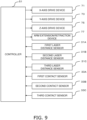
- Fig. 9 is a block diagram illustrating the control structure of the tire transport apparatus.
- the controller 51 determines that two stacked tires T from the top can be transported, for example. This is, for example, a case where the lowest tire T is in an appropriate position, but upper tires T are tilted so that there is a difference between the detected distances as described above.
Landscapes
- Engineering & Computer Science (AREA)
- Mechanical Engineering (AREA)
- Automation & Control Theory (AREA)
- Manipulator (AREA)
- Load-Engaging Elements For Cranes (AREA)
- Carriers, Traveling Bodies, And Overhead Traveling Cranes (AREA)
- Length Measuring Devices By Optical Means (AREA)
- Tyre Moulding (AREA)
Abstract
Description
- The present invention relates to a tire transport apparatus, in particular an apparatus that inserts a plurality of arms inside an upper opening edge of a center hole of a tire in a lying position from above, so as to lift the tire by supporting the upper opening edge with hooks of the arms from below.
- The tire transport apparatus includes the plurality of arms each having the hook formed at the distal end, an arm extension/retraction mechanism to move the arms in a horizontal extension/retraction direction, and a lift mechanism to raise and lower the arms and the arm extension/retraction mechanism.
- The tire transport apparatus lowers the plurality of arms from above of an upper opening of the center hole of the tire in a lying position, so as to insert the same into the upper opening, and then moves the arms in an extension direction so that the hooks move to below the upper opening edge. Lastly, the tire transport apparatus moves the arms upward so that the hooks support the upper opening edge of the tire from below, and lifts the tire.
- For instance, there is known an article transfer apparatus that inserts four arms into the bore of the tire to transfer the tire (see Patent Citation 1, for example).
- Patent Citation 1:
JP-A-2008-162733 - In general, tires are stacked and stored. Further, the stacked tires may be deformed and tilted as time elapses. It is because the tires are soft and sticky.
- On the other hand, the tire transport apparatus performs stop control in predetermined coordinates. Therefore, if the stacked tires are tilted as described above, the hook may hit the tilted tire when the arm is lowered. In this case, the tire cannot be transported and might be damaged as well.
- It is an object of the present invention to ensure that the arm can hardly damage the tire when the tire transport apparatus holds the tire.
- As means for solving the problem, a plurality of embodiments are described below. These embodiments can be arbitrarily combined as necessary.
- A tire transport apparatus according to one aspect of the present invention, which is an apparatus for lifting and transporting a tire, includes at least three arms, an arm extension/retraction mechanism, a lift mechanism, at least three optical reflection sensors, and a controller.
- The at least three arms each have an arm main body and a protrusion disposed to protrude outward at a lower part of the arm main body for lifting the tire.
- The arm extension/retraction mechanism moves the arms in a horizontal extension/retraction direction.
- The lift mechanism raises and lowers the arms.
- The at least three optical reflection sensors are disposed on the outer side of a circle including distal ends of the protrusions when the arms are above the tire and in a retracted state, so as to detect an object below. Note that the optical reflection sensor is a sensor that can detect reflected light when emitting light downward. In addition, "downward" means an area just below the optical reflection sensor or an area just below the same and vicinity thereof. As described later, the optical reflection sensor may be a distance sensor that detects a distance to an object below. The optical reflection sensor may be not a distance sensor but a sensor that simply detect an object below.
- If at least one of the optical reflection sensors detects the tire, the controller determines that the arms are in an inappropriate position.
- In this apparatus, as a basic transport operation, the lift mechanism lowers the arms to locate the same inside the tire, and then the arm extension/retraction mechanism extends the arm main bodies of the three arms outward in the horizontal direction, and lastly the lift mechanism raises the arms so as to lift the tire using the protrusions of the arms.
- In this apparatus, if the optical reflection sensor detects the tire, it means that the tire is located at a position overlapping the protrusion in a plan view. In this case, for example, the lift mechanism does not lower the arms. Therefore, the protrusion does not contact the tire if the tire is tilted or in an inappropriate position.
- If none of the optical reflection sensors detects the tire, the controller determines that the arms are in an appropriate position. Then, the controller performs the operation to lift the tire. Specifically, the controller lowers the arms, extends the arm main bodies outward in the horizontal direction, and raises the arms so as to lift the tire using the protrusions of the arms.
- If at least one of the optical reflection sensors detects the tire, the controller may move the at least three arms in the direction from the laser distance sensor that has detected the tire toward the center of the circle. By moving the arms, the position of the arms is corrected.
- The optical reflection sensor may be a laser distance sensor.
- The controller may monitor the distances measured by the laser distance sensors, and if there is a difference between the distances measured by the laser distance sensors, the controller may determine that the tire is detected by the optical reflection sensor. Note that the distance measured by the laser distance sensor means a distance between the laser distance sensor and an object (the tire or a floor or the like) just below the laser distance sensor.
- In this apparatus, using the laser distance sensors, it is possible to accurately detect presence or absence of the tire. Specifically, there is the tire just below the sensor that detected a short distance.
- Note that in this specification, the case where the optical reflection sensor does not detect the tire includes the case where the laser distance sensor detects a distance, which is a distance to an object other than the tire. In addition, the case where the optical reflection sensor detects the tire includes the case where the laser distance sensor detects a distance, which is a distance to the tire.
- The controller may move the arms in the direction from the laser distance sensor that has detected the short distance toward the center of the circle, and then may monitor the distances measured by the laser distance sensors.
- In this apparatus, by moving the arms in the direction where the laser distance sensor just above the tire separates from the tire, the position of the arms is corrected. As a result, the protrusion hardly contacts the tire, and thus transportation of the tire can be continued.
- The controller may determine the number of tires that can be transported, on the basis of a difference between the distances measured by the laser distance sensors.
- In this apparatus, also in the case where there is a difference between the distances measured by the laser distance sensors, only the transportable number of tires can be transported. Therefore, transport efficiency of the tires can be improved.
- The tire transport apparatus may further include a contact sensor disposed at a bottom surface of the protrusion so as to detect contact between a distal end side of the protrusion and an object below.
- If the contact sensor detects the tire during lowering of the arm, the controller may control the lift mechanism to stop further lowering of the arm.
- In this apparatus, if the contact sensor at the lower end of the arm contacts the tire, lowering of the arm is stopped. In this way, damage to the tire is prevented. The detection of the tire by the contact sensor in this way means that the tire exists in a position in which it interferes with the protrusion though the optical reflection sensor was not able to detect it.
- When the tire transport apparatus according to the present invention holds a tire, the arms of the tire transport apparatus hardly damage the tire.
-
-
Fig. 1 is a schematic front view of a tire transport apparatus. -
Fig. 2 is a schematic perspective view illustrating a positional relationship among arms of the tire transport apparatus, laser distance sensors thereof, and tires. -
Fig. 3 is a plan view illustrating a positional relationship among hooks and the laser distance sensors. -
Fig. 4 is a partial side view illustrating a lower part of the arm, the hook, and a contact sensor. -
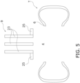
Fig. 5 is a schematic diagram illustrating one state of a tire lifting operation. -
Fig. 6 is a schematic diagram illustrating one state of the tire lifting operation. -
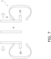
Fig. 7 is a schematic diagram illustrating one state of the tire lifting operation. -
Fig. 8 is a schematic diagram illustrating one state of the tire lifting operation. -
Fig. 9 is a block diagram illustrating a control structure of the tire transport apparatus. -
Fig. 10 is a flowchart illustrating a tire lift control operation of the tire transport apparatus. -
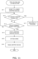
Fig. 11 is a flowchart illustrating the tire lift control operation of the tire transport apparatus. -
Fig. 12 is a schematic plan view illustrating one state of a positional relationship between the tire and the laser distance sensors. -
Fig. 13 is a schematic plan view illustrating one state of the positional relationship between the tire and the laser distance sensors. -
Fig. 14 is a schematic plan view illustrating one state of the positional relationship between the tire and the laser distance sensors. - With reference to
Fig. 1 , atire transport apparatus 1 is described.Fig. 1 is a schematic front view of the tire transport apparatus. - The
tire transport apparatus 1 is an apparatus or a facility that transports a tire T in a horizontally held and lifted state (in a state where the meridian cross section of the tire becomes substantially horizontal). Specifically, it moves, stacks, or destacks the tires T. Note that inFig. 1 , the direction perpendicular to the paper is a first direction (arrow X), and the left and right direction is a second direction (arrow Y). The vertical direction is shown by an arrow Z. - Note that the tire T is a rubber hollow member having a center hole 4 (see
Fig. 2 ). - The
tire transport apparatus 1, which has a structure called a gantry crane, includes a pair offirst rails 3, asecond rail 5, and amobile unit 7. - The pair of
first rails 3 are disposed at positions above the ground to extend in the first direction in parallel with each other, and are separate from each other in the second direction. - The
second rail 5 extends in the second direction between the pair offirst rails 3, and is driven by an X-axis drive device 71 (seeFig. 9 ) so that it can move along the pair offirst rails 3 in the first direction. - The
mobile unit 7 is supported by thesecond rail 5 and is driven by a Y-axis drive device 73 (seeFig. 9 ) so that it can move along thesecond rail 5 in the second direction. - The
tire transport apparatus 1 includes agripper device 9. Thegripper device 9 is mounted to themobile unit 7 in a vertically movable manner, and is a device that grips and transports the tire T. Specifically, thegripper device 9 grips the tire T from inside to lift it up, and then moves it horizontally to transfer it. - The
tire transport apparatus 1 includes a Z-axis drive device 75. The Z-axis drive device 75 is a mechanism for raising and lowering thegripper device 9 mounted to a lower part thereof. The Z-axis drive device 75, which is a known technique, includes a belt (not shown) that hangs and supports thegripper device 9, a hoisting device that winds and rewinds the belt to raise and lower thegripper device 9, and the like, for example. - The
gripper device 9 includes a base 21 fixed to the Z-axis drive device 75, and threearms 23 extending downward from the base 21 in the vertical direction. - The
base 21 is a lift platform and is hanged in the vertical direction from themobile unit 7 by the belt (not shown) of the Z-axis drive device 75. - The three
arms 23 are arranged at regular intervals in the circumferential direction of a predetermined circle with angles of 120 degrees between them. - A lower end of an arm
main body 24 of eacharm 23 is provided with ahook 25 that protrudes and extends outward in the horizontal direction. Thehook 25 engages with an upper bead part of the tire T from below. In the state where the threehooks 25 of the threearms 23 are engaged with the upper bead part of one tire T from below, the threearms 23 are raised, and the tire can be lifted up. - A touch sensor (not shown) may be mounted to an outer side surface of the
arm 23. This touch sensor is used for detecting that a main body of thearm 23 contacts an upper opening edge of thecenter hole 4 of the tire T when thearm 23 is moved outward. - The
gripper device 9 includes an arm extension/retraction device 77 (seeFig. 9 ). The arm extension/retraction device 77 is a chuck device that extends/retracts the threearms 23 in the horizontal radial direction (i.e., it switches them between an extended state and a retracted state). The arm extension/retraction device 77 is mounted to thebase 21. - The arm extension/
retraction device 77, which is a known technique, includes a chuck cylinder (not shown), and an interlocking mechanism (not shown) for moving thearms 23 in an interlocking manner, for example. - Note that the
arms 23 are separated from each other most in the circumferential direction in the extended state, while they are close to each other most in the circumferential direction in the retracted state. - The
gripper device 9 includes a firstlaser distance sensor 31A, a secondlaser distance sensor 31B, and a thirdlaser distance sensor 31C. The first to thirdlaser distance sensors 31A to 31C are used for detecting distances in the height direction between the base 21 of thegripper device 9 and an object below. The first to thirdlaser distance sensors 31Ato 31C are mounted to a lower part of thebase 21, and are configured to emit laser beams right downward, i.e., downward in the vertical direction. - The first to third
laser distance sensors 3 1A to 31C are each arranged between thehooks 25 in the circumferential direction as illustrated inFigs. 2 and 3 , and specifically with angles of 120 degrees between them on a predetermined circle. More specifically, the first to thirdlaser distance sensors 31A to 31C are disposed on the outer side of a first circle C1 including the distal ends of thehooks 25 when thearms 23 are retracted most (as an example of the retracted state). - In this embodiment, the first to third
laser distance sensors 31A to 31C are disposed adjacent to the first circle C1. However, it is sufficient that the first to thirdlaser distance sensors 31A to 31C are disposed between the first circle C1 and a second circle C2 including the distal ends of thehooks 25 when thearms 23 are extended most (as an example of the extended state). In other words, the first to thirdlaser distance sensors 31A to 31C are disposed in an area outside the first circle C1 and inside the second circle C2. Note that the first to thirdlaser distance sensors 31A to 31C may be disposed apart from the first circle C1 outward in the radial direction. In addition, the first to thirdlaser distance sensors 31A to 31C may not be aligned in the circumferential direction. In other words, the first to thirdlaser distance sensors 31A to 31C may be disposed to have different distances from the center. - As described above, the first to third
laser distance sensors 31A to 31C are disposed on the outer side of the first circle C1 including the distal ends of thehooks 25 when thearms 23 are above the tire T and in the retracted state, so as to detect an object below. - The
gripper device 9 is equipped with first tothird contact sensors 33A to 33C (seeFig. 9 ), each of which is mounted to the bottom surface of thehook 25, and moves vertically at a side of the distal end of thehook 25. The first tothird contact sensors 33A to 33C are each a sensor for detecting that the bottom surface of thehook 25 has abut the top surface of the tire T during lowering of thearms 23. - With reference to
Fig. 4 , thefirst contact sensor 33A is described as an example of the contact sensor.Fig. 4 is a partial side view illustrating a lower part of the arm, the hook, and the contact sensor. - The
first contact sensor 33A has aplate 81 that rocks vertically. A distal end side of theplate 81 is pivoted by apivot shaft 81a extending in the horizontal direction at the lower part of thearm 23. Theplate 81 can move between a horizontal position in which it abuts amain body 25a of thehook 25 and an inclined position at which the distal end is separated downward. - The
first contact sensor 33A has a spring (not shown, such as a coil spring) that elastically biases theplate 81 downward in the rocking direction. Therefore, theplate 81 is normally in the inclined position. - The
first contact sensor 33A has a load cell (not shown). The load cell is positioned so that it is compressed between theplate 81 and another member of thehook 25 when theplate 81 contacts an object below and rocks upward to the horizontal position. - With reference to
Figs. 5 to 8 , there is described a basic operation of thetire transport apparatus 1 when it lifts the tire T in a lying position.Figs. 5 to 8 are schematic diagrams each illustrating one state of the tire lifting operation. - First, as illustrated in
Fig. 5 , thegripper device 9 is located just above the tire T (i.e., just above the center hole). - Next, as illustrated in
Fig. 6 , the threearms 23 in the retracted state are lowered to enter inside anupper opening edge 6, so that the distal ends of thehooks 25 are positioned in the center or its vicinity of the tire T in the vertical direction. - Next, as illustrated in
Fig. 7 , the threearms 23 are extended in the radial direction of the tire, and thehooks 25 are moved to positions to engage the upper opening edge 6 (bead part) of the tire T in a plan view. - Lastly, as illustrated in
Fig. 8 , thearms 23 are raised, and thehooks 25 support theupper opening edge 6 of thecenter hole 4 of the tire T from below to lift the same. - With reference to
Fig. 9 , a control structure of thetire transport apparatus 1 is described.Fig. 9 is a block diagram illustrating the control structure of the tire transport apparatus. - The
tire transport apparatus 1 includes acontroller 51. - The
controller 51 is a computer system including a processor (such as a CPU), a storage device (such as a ROM, a RAM, an HDD, or an SSD), and various interfaces (such as an A/D converter, a D/A converter, and a communication interface). Thecontroller 51 performs various control operations by executing a program stored in a storage section (corresponding to a part or the whole of storage area of the storage device). - The
controller 51 may be constituted of a single processor, or may be constituted of a plurality of independent processors for individual controls. - A part or the whole of functions of individual components of the
controller 51 may be realized as a program that can be executed by the computer system constituting thecontroller 51. Other than that, a part of functions of individual components of thecontroller 51 may be constituted of a custom IC. - The
controller 51 is connected to theX-axis drive device 71, the Y-axis drive device 73, the Z-axis drive device 75, and the arm extension/retraction device 77. Thecontroller 51 can control these devices. - The
controller 51 is connected to the first to thirdlaser distance sensors 31A to 31C, and the first tothird contact sensors 33A to 33C. Thecontroller 51 receives detection signals from these sensors. - Although not illustrated, the
controller 51 is connected to sensors and switches for detecting states of individual devices, and to an information input device. - With reference to
Figs. 10 to 14 , details of the tire lift control operation are described.Figs. 10 and11 are flowcharts illustrating the tire lift control operation of the tire transport apparatus.Figs. 12 to 14 are schematic plan views each illustrating one state of a positional relationship between the tire and the laser distance sensors. - The control flowchart described below is an example, and individual steps may be omitted or exchanged with each other as necessary. In addition, a plurality of steps may be executed simultaneously, or a part or the whole of them may be executed in an overlapping manner.
- Further, each block in the control flowchart is not necessarily a single control operation but can be replaced by a plurality of control operations expressed in a plurality of blocks.
- Note that operations of individual devices are results of commands from a control unit to the devices, which can be expressed by steps of a software application.
- In Step S1, the
mobile unit 7 is moved and stopped at a position just above the tire T. Specifically, thecontroller 51 controls theX-axis drive device 71 and the Y-axis drive device 73 to perform the operation described above. Note that the position of the tire T is stored in advance in the storage section of thecontroller 51. - In Step S2, the
arms 23 are moved to the innermost positions (i.e., they come to the retracted state). Specifically, thecontroller 51 controls the arm extension/retraction device 77 to perform the operation described above. Note that the above operation is omitted if thearms 23 are initially in the retracted state. - In Step S3, the
gripper device 9 is lowered to a predetermined height. Specifically, thecontroller 51 controls the Z-axis drive device 75 to perform the operation described above. The predetermined height described above is, for example, a height such that a distance in the height direction between the lower part bottom surface of thearm 23 and the topmost surface of the tire T becomes a predetermined value (such as 300 mm). Note that the height of the topmost surface of the tire T is stored in advance in the storage section of thecontroller 51. - In Step S4, the first to third
laser distance sensors 31A to 31C each emit the laser beam downward and receive the reflected laser beam so as to detect a distance to an object below. At this time, thegripper device 9 is lowered as described above so that the first to thirdlaser distance sensors 31A to 31C are close to the tire T, and hence detection accuracy is improved. - In Step S5, it is determined whether or not there is a difference between distances between the first to third
laser distance sensors 31A to 31C and an object below. If Yes, the process proceeds to Step S6. If No, the process proceeds to Step S9. - The case of Yes in Step S5 means, for example, a case as illustrated in
Fig. 12 , where two of the first to thirdlaser distance sensors 31A to 31C are located just above thecenter hole 4 of the tire T, but one of them is located just above the tire T and has a measured distance shorter than those of other two. This is a case where thearms 23 are in an inappropriate position, and one of thehooks 25 will abut the tire T when thearms 23 are lowered. - The case of No in Step S5 means a case as illustrated in
Fig. 13 , where all the first to third laserdistance sensors 31Ato 31C are located just above thecenter hole 4 of the tire T. - In Step S6, it is determined whether or not the above determination has been made more than a predetermined number of times. If Yes, the process proceeds to Step S8. If No, the process proceeds to S7.
- In Step S7, the
gripper device 9 is moved in the horizontal direction. Note that the movement distance is 5 to 10 mm, for example. Specifically, as illustrated by a white arrow inFig. 12 , thecontroller 51 moves thegripper device 9, i.e. thearms 23 so that one of the first to thirdlaser distance sensors 31A to 31C that detected a short distance comes to inside thecenter hole 4 of the tire T in a plan view (e.g., in the direction toward the center of the circle), and then monitors the distances measured by the first to thirdlaser distance sensors 31Ato 31C. Therefore, the position of thearms 23 is corrected. As a result, thearms 23 hardly contact the tire T. When Step S7 is finished, the process returns to Step S4. - Note that if two of the first to third
laser distance sensors 31A to 31C are located just above the tire T and have measured distances shorter than that of the other one as illustrated inFig. 14 , thecontroller 51 moves thegripper device 9, i.e. thearms 23 so that two of the first to thirdlaser distance sensors 31A to 31C that detected short distances come to inside thecenter hole 4 of the tire T in a plan view, as illustrated by a white arrow inFig. 14 . - In Step S8, an abnormality process is performed. Specifically, an abnormality alarm is generated. After that, an operator performs a process to resolve the abnormal state by manual operation, manual work, or the like.
- In Step S9, a tire holding and lifting operation is performed (as described later).
- As described above, the
controller 51 monitors the distances measured by the first to thirdlaser distance sensors 31A to 31C, and if the tire T is not detected, it controls the Z-axis drive device 75 to lower thearms 23 to hold the tire T. - On the other hand, if there is a difference between the distances measured by the first to third
laser distance sensors 31Ato 31C (i.e., if any of the first to thirdlaser distance sensors 31A to 31C detects the tire T), thecontroller 51 does not allow the Z-axis drive device 75 to lower thearms 23. This means that if at least one of the first to thirdlaser distance sensors 31A to 31C detects the tire T, the measured distance of the sensor becomes shortest, and the tire exists just below the sensor. In other words, the tire T is located in a position overlapping with thehook 25 in a plan view (e.g., the tire T is tilted or in an inappropriate position). In other words, thecontroller 51 determines that thearms 23 are in an inappropriate position. - In addition, if at least one of the first to third
laser distance sensors 31A to 31C is not inside thecenter hole 4 of the tire T in a plan view as described above, correction of the horizontal position of thegripper device 9 and remeasurement of the distances below are repeatedly performed. In other words, if there is a difference between the measured distances (Yes in Step S5), thegripper device 9 is moved by a predetermined distance (such as a few millimeters) in Step S7, and the distances to the tire T are measured again in Step S5. Note that a significant difference between the measured distances is, for example, more than a predetermined value such as 30 to 50 mm. - With reference to
Fig. 11 , Step S9 ofFig. 10 is described in detail. - In Step S11, lowering of the
gripper device 9 is started from the state ofFig. 5 , for example. Specifically, thecontroller 51 controls the Z-axis drive device 75 to perform the operation described above. - In Step S12, it is determined whether or not at least one of the first to
third contact sensors 33A to 33C is turned on. Specifically, thecontroller 51 performs the above determination based on the detection signals from the first tothird contact sensors 33A to 33C. If Yes, the process proceeds to Step S17. If No, the process proceeds to Step S13. - In Step S13, it is determined whether or not the
gripper device 9 has reached a predetermined height position. Specifically, thecontroller 51 performs the above determination based on a detection signal from a sensor (not shown). If Yes, the process proceeds to Step S14. If No, the process returns to Step S12. - In Step S14, lowering of the
gripper device 9 is stopped (e.g., the state ofFig. 6 ). Specifically, thecontroller 51 controls the Z-axis drive device 75 to perform the operation described above. - In Step S15, the three
arms 23 are moved outward in the radial direction (e.g., the state ofFig. 7 ). Specifically, thecontroller 51 controls the arm extension/retraction device 77 to perform the operation described above. In this way, thehooks 25 are positioned below theupper opening edge 6 of thecenter hole 4 of the tire T. Note that, the movement of the threearms 23 is stopped based on the detection signal of the touch sensor or the like, when the main body of thearm 23 abuts the upper opening edge of thecenter hole 4 of the tire T. - In Step S16, the
gripper device 9 is raised (e.g., the state ofFig. 8 ). Specifically, thecontroller 51 controls the Z-axis drive device 75 to perform the operation described above. In this way, thearms 23 are raised, and thehooks 25 of thearms 23 support the upper opening edge of thecenter hole 4 of the tire T from below so as to lift the entire tire T. - In Step S17, the abnormality process is performed. Specifically, further lowering of the
arm 23 is stopped. Furthermore, the abnormality alarm is generated, and after that, the operator performs the process to resolve the abnormal state by manual operation, manual work, or the like. In this way, if at least one of the first tothird contact sensors 33A to 33C has detected the tire T, the abnormality process is promptly performed without performing position correction, unlike the case where at least one of the first to thirdlaser distance sensors 31A to 31C has detected the tire T. This is because it is considered in the above case that the tire T is in a state with which the adjustment such as the position correction cannot deal. - In the first embodiment, if the correction operation of Step S7 of
Fig. 10 has been performed a plurality of times, but in vain, the abnormality process is performed in Step S8. - As a variation of the above operation, a second embodiment is described. Note that the basic structure and operation of the second embodiment are the same as those of the first embodiment.
- Between Step S5 and Step S6 of
Fig. 10 , thecontroller 51 performs a new step, in which it is determined how many stacks of the tires T from the top can be transported, on the basis of the detection results of the first to thirdlaser distance sensors 31A to 31C. Then, if there is any transportable tire T, the process proceeds to Step S9, in which the tire holding and lifting operation is performed. Note that in the above tire holding and lifting operation, it may be possible to transport the transportable tires T in bulk, or to transport them one by one. - In the above case, if there is a difference between the detected distances because of tilting of upper tires T, for example, after transporting the tilted upper tires T as described above, lower tires T can also be transported next.
- As results of the above, if there is a difference between the distances measured by the first to third
laser distance sensors 31A to 31C, only the transportable number of tires T can be transported. Therefore, transport efficiency of the tires T can be improved. - A specific example is described below. As illustrated in
Fig. 1 , it is supposed that there are three stacked tires T, the tire width is 200 mm, and the total height of the three tires is 600 mm. Note that thecontroller 51 has recognized that there are three stacked tires T based on inventory data. - First, as illustrated in Steps S4 and S5 of
Fig. 10 , at 300 mm above the tire T, the first to thirdlaser distance sensors 31A to 31C detect the distances to the tire T. - In this embodiment, suppose that the correction operation in Step S7 of
Fig. 10 is performed once, but a difference between the distances is not canceled, and after that, in Step S5, there is again a difference between the distances (Yes in Step S5). Then, thecontroller 51 performs a new step, in which it is determined how many stacks of the tires T from the top can be transported, on the basis of the detection results of the first to third laserdistance sensors 31Ato 31C. - For instance, it is supposed that two sensors among the first to third
laser distance sensors 31A to 31C have a detection result of 900 mm (the tire T is not detected), while one sensor has a detection result of 700 mm (the lowest tire T is detected). In this example, thecontroller 51 determines that two stacked tires T from the top can be transported, for example. This is, for example, a case where the lowest tire T is in an appropriate position, but upper tires T are tilted so that there is a difference between the detected distances as described above. - Then, next in Step S9 of
Fig. 10 , the upper two stacked tires T are transported. - Next, the
mobile unit 7 returns to the position above the lowest tire T. - Lastly, the
tire transport apparatus 1 detects the lowest tire T, and transports the same. - The above embodiment can also be described as follows.
- The tire transport apparatus 1 (an example of the tire transport apparatus), which is an apparatus for lifting and transporting a tire, includes the at least three
arms 23, the arm extension/retraction device 77, the Z-axis drive device 75, and thecontroller 51. - The three arms 23 (an example of the arms) each include the arm main body 24 (an example of the arm main body), and the hook 25 (an example of the protrusion) disposed to protrude outward at the lower part of the arm
main body 24 for lifting the tire. - The arm extension/retraction device 77 (an example of the arm extension/retraction mechanism) moves the
arms 23 in the horizontal extension/retraction direction. - The Z-axis drive device 75 (an example of the lift mechanism) raises and lowers the
arms 23. - The first to third
laser distance sensors 31A to 31C are disposed on the outer side of the first circle C1 (an example of the circle) including the distal ends of thehooks 25 when thearms 23 are above the tire T and in the retracted state, so as to detect an object below. - If at least one of the first to third
laser distance sensors 31A to 31C detects the tire T, thecontroller 51 determines that thearms 23 are in an inappropriate position. - In this apparatus, if one of the first to third
laser distance sensors 31A to 31C detects the tire T, it means that the tire T is located at a position overlapping thehook 25 in a plan view. In this case, for example, the Z-axis drive device does not lower thearms 23. Therefore, thehooks 25 does not contact the tire T if the tire T is tilted or in an inappropriate position. - Although a plurality of embodiments of the present invention are described above, the present invention is not limited to the above embodiments, and can be variously modified within the scope of the invention without deviating from the spirit thereof. In particular, the plurality of embodiments and variations described in this specification can be arbitrarily combined as necessary.
- The number of the arms may be four or more. For instance, it may be four or five.
- In the first embodiment, in order to adjust the position of the arms, the arms are moved by a predetermined distance (a few millimeters), and the laser distance sensors detect an object blow again. However, as a variation, it may be possible to continuously move the arms while measuring distances to an object below. In this case, the arms are moved until the tire T becomes not detected.
- The arm position adjustment may be omitted.
- There may be three or more laser distance sensors. For instance, there may be four, five, or six laser distance sensors. Note that it is preferred that one laser distance sensor is disposed between the arms.
- It may be possible to use, instead of the laser distance sensor, a reflection type photoelectric sensor that detects presence or absence of a reflecting object. In this case, presence or absence of the tire T just below the sensor can be detected, and the controller can discriminate between presence and absence of the tire T.
- It may be not necessary to lower the gripper device prior to the detection by the laser distance sensors. In addition, it may be possible to perform the detection by the laser distance sensors while lowering the gripper device.
- The type and structure of the contact sensor, and the number of the contact sensors are not limited as long as they can detect contact between the bottom surface of the hook and an object below. For instance, the contact sensor may include a contacting member that moves vertically, a linear motion guide that guides the contacting member in the vertical direction, a spring that biases the contacting member downward, and a load cell that is compressed between the contacting member and another member of the hook when the contacting member contacts an object below and moves upward.
- The contact sensor may be omitted.
- The tire transport apparatus may be mounted to an overhead transport vehicle that travels in a predetermined height position, without limiting to the gantry crane.
- The present invention can be widely applied to apparatuses that lift a tire by inserting a plurality of arms from above inside an upper opening edge of the center hole of a tire in a lying position so that hooks of the arms support the upper opening edge from below.
-
- 1
- tire transport apparatus
- 3
- first rail
- 5
- second rail
- 7
- mobile unit
- 9
- gripper device
- 21
- base
- 23
- arm
- 25
- hook
- 31A
- first laser distance sensor
- 31B
- second laser distance sensor
- 31C
- third laser distance sensor
- 33A
- first contact sensor
- 33B
- second contact sensor
- 33C
- third contact sensor
- 51
- controller
- 71
- X-axis drive device
- 73
- Y-axis drive device
- 75
- Z-axis drive device
- 77
- arm extension/retraction device
Claims (7)
- A tire transport apparatus comprising:at least three arms each having an arm main body and a protrusion disposed to protrude outward at a lower part of the arm main body for lifting the tire;an arm extension/retraction mechanism configured to move the at least three arms in a horizontal extension/retraction direction;a lift mechanism configured to raise and lower the at least three arms;at least three optical reflection sensors disposed on the outer side of a circle including distal ends of the protrusions when the at least three arms are above the tire and in a retracted state, so as to detect an object below; anda controller configured to determine that one or more arms among the at least three arms are in an inappropriate position, if one or more optical reflection sensors among the at least three optical reflection sensors detect the tire.
- The tire transport apparatus according to claim 1, wherein if none of the at least three optical reflection sensors detects the tire, the controller performs the operation to lift the tire.
- The tire transport apparatus according to claim 1, wherein if one or more optical reflection sensors among the at least three optical reflection sensors detect the tire, the controller moves the at least three arms in the direction from the optical reflection sensor that has detected the tire toward the center of a circle connecting the three optical reflection sensors.
- The tire transport apparatus according to claim 1, whereinthe optical reflection sensor is a laser distance sensor, andthe controller monitors distances measured by the laser distance sensors, and determines that the optical reflection sensor has detected the tire if there is a difference between the distances measured by the laser distance sensors.
- The tire transport apparatus according to claim 4, wherein the controller moves the at least three arms in the direction from the laser distance sensor that has detected a short distance toward the center of a circle connecting the three laser distance sensors, and then monitors the distances measured by the laser distance sensors.
- The tire transport apparatus according to any one of claims 1 to 3, further comprising a contact sensor disposed at a bottom surface of the protrusion so as to detect contact between a distal end side of the protrusion and an object below, wherein
if the contact sensor detects the tire during lowering of the arm, the controller controls the lift mechanism to stop further lowering of the at least three arms. - The tire transport apparatus according to claim 4, wherein the controller determines the number of tires that can be transported, on the basis of a difference between the distances measured by the laser distance sensors.
Applications Claiming Priority (2)
| Application Number | Priority Date | Filing Date | Title |
|---|---|---|---|
| JP2021008143 | 2021-01-21 | ||
| PCT/JP2021/041586 WO2022158092A1 (en) | 2021-01-21 | 2021-11-11 | Tire transport apparatus |
Publications (3)
| Publication Number | Publication Date |
|---|---|
| EP4253301A1 true EP4253301A1 (en) | 2023-10-04 |
| EP4253301A4 EP4253301A4 (en) | 2024-10-30 |
| EP4253301B1 EP4253301B1 (en) | 2026-04-22 |
Family
ID=82548738
Family Applications (1)
| Application Number | Title | Priority Date | Filing Date |
|---|---|---|---|
| EP21921195.0A Active EP4253301B1 (en) | 2021-01-21 | 2021-11-11 | Tire transport apparatus |
Country Status (6)
| Country | Link |
|---|---|
| US (1) | US12378084B2 (en) |
| EP (1) | EP4253301B1 (en) |
| JP (1) | JP7448040B2 (en) |
| KR (1) | KR102843523B1 (en) |
| CN (1) | CN116710386B (en) |
| WO (1) | WO2022158092A1 (en) |
Families Citing this family (1)
| Publication number | Priority date | Publication date | Assignee | Title |
|---|---|---|---|---|
| CN116621018B (en) * | 2023-05-31 | 2023-12-22 | 荣成荣鹰橡胶制品有限公司 | Solid tire clamping and transferring device and using method |
Family Cites Families (26)
| Publication number | Priority date | Publication date | Assignee | Title |
|---|---|---|---|---|
| JPS597032A (en) * | 1982-07-06 | 1984-01-14 | Mitsubishi Heavy Ind Ltd | Green tire supply device |
| JP3136446B2 (en) * | 1991-12-27 | 2001-02-19 | 横浜ゴム株式会社 | Supplying green tires to vulcanizers and adjusting the angle |
| JPH06126678A (en) * | 1992-10-16 | 1994-05-10 | Kirin Brewery Co Ltd | Cylindrical container gripping device |
| JPH06183682A (en) * | 1992-12-17 | 1994-07-05 | Mitsubishi Heavy Ind Ltd | Hoisting accessory for carrying ring-shaped member such a tire |
| JPH0761602A (en) * | 1993-08-27 | 1995-03-07 | Mitsubishi Heavy Ind Ltd | Tire transfer device |
| JP2003020190A (en) * | 2001-07-11 | 2003-01-21 | Nippon Yusoki Co Ltd | Roll lifting device |
| JP2004238147A (en) * | 2003-02-06 | 2004-08-26 | Okura Yusoki Co Ltd | Holding device and transfer machine |
| JP4224784B2 (en) * | 2003-07-18 | 2009-02-18 | 株式会社ダイフク | Gripping part raising and lowering transfer device |
| JP5082437B2 (en) | 2006-12-27 | 2012-11-28 | 村田機械株式会社 | Article transfer device |
| JP4941451B2 (en) * | 2008-10-20 | 2012-05-30 | 三菱自動車工業株式会社 | Tire gripping device |
| WO2013088950A1 (en) * | 2011-12-16 | 2013-06-20 | 株式会社ブリヂストン | Tire printing method and tire printing device |
| US9428334B2 (en) * | 2013-05-17 | 2016-08-30 | The Heil Co. | Automatic control of a refuse front end loader |
| CN203422070U (en) * | 2013-08-14 | 2014-02-05 | 贵州轮胎股份有限公司 | Device for detecting angle and direction of specific point of tyre |
| JP6240689B2 (en) * | 2015-07-31 | 2017-11-29 | ファナック株式会社 | Machine learning device, robot control device, robot system, and machine learning method for learning human behavior pattern |
| CN204872926U (en) * | 2015-08-28 | 2015-12-16 | 山东昊华轮胎有限公司 | All steel load radial tire stacker |
| JP6567388B2 (en) * | 2015-10-20 | 2019-08-28 | 株式会社小野測器 | Tire mounting system |
| EP3460834B1 (en) * | 2016-05-20 | 2020-08-05 | Murata Machinery, Ltd. | Transport vehicle and transport method |
| CN107098260B (en) * | 2017-06-08 | 2018-06-22 | 北京天朔新能源汽车有限公司 | A kind of automatic handling robot of electric vehicle special (purpose) rubber tire |
| CN112938766B (en) * | 2017-09-05 | 2023-08-15 | 住友重机械搬运系统工程株式会社 | crane device |
| JP7135411B2 (en) * | 2018-05-02 | 2022-09-13 | 村田機械株式会社 | Conveyor system |
| JP7040640B2 (en) | 2018-11-19 | 2022-03-23 | 村田機械株式会社 | Posture change device |
| WO2020163383A1 (en) * | 2019-02-04 | 2020-08-13 | The Heil Co. | Semi-autonomous refuse collection |
| US11208262B2 (en) * | 2019-04-23 | 2021-12-28 | The Heil Co. | Refuse container engagement |
| US11453550B2 (en) * | 2019-04-23 | 2022-09-27 | The Heil Co. | Refuse collection vehicle controls |
| NL2023215B1 (en) * | 2019-05-28 | 2020-12-07 | Vmi Holland Bv | Bead-apex storage system and method for handling a plurality of stacks with bead-apexes and spacers |
| WO2021157117A1 (en) * | 2020-02-06 | 2021-08-12 | 村田機械株式会社 | Clamping device and stacking device |
-
2021
- 2021-11-11 JP JP2022576993A patent/JP7448040B2/en active Active
- 2021-11-11 CN CN202180087797.1A patent/CN116710386B/en active Active
- 2021-11-11 KR KR1020237021683A patent/KR102843523B1/en active Active
- 2021-11-11 WO PCT/JP2021/041586 patent/WO2022158092A1/en not_active Ceased
- 2021-11-11 US US18/273,050 patent/US12378084B2/en active Active
- 2021-11-11 EP EP21921195.0A patent/EP4253301B1/en active Active
Also Published As
| Publication number | Publication date |
|---|---|
| US20240083695A1 (en) | 2024-03-14 |
| WO2022158092A1 (en) | 2022-07-28 |
| EP4253301B1 (en) | 2026-04-22 |
| KR20230111239A (en) | 2023-07-25 |
| EP4253301A4 (en) | 2024-10-30 |
| CN116710386A (en) | 2023-09-05 |
| CN116710386B (en) | 2026-03-27 |
| US12378084B2 (en) | 2025-08-05 |
| JP7448040B2 (en) | 2024-03-12 |
| KR102843523B1 (en) | 2025-08-07 |
| JPWO2022158092A1 (en) | 2022-07-28 |
Similar Documents
| Publication | Publication Date | Title |
|---|---|---|
| JP5945968B2 (en) | Robot hand, robot system, and article depalletizing method | |
| CN103459271B (en) | Automated warehouse | |
| US10494178B2 (en) | Teaching apparatus, transport system, and method for measuring positioning pins | |
| US11066248B2 (en) | Article transport device | |
| US10431485B2 (en) | Article transport facility | |
| KR102709730B1 (en) | Overhead transport vehicle | |
| US10134620B2 (en) | Robot system and incline detection method | |
| JP2009179454A (en) | Automated warehouse, and method for controlling the same | |
| KR101548920B1 (en) | Teaching system of transportation robot and teaching method using it | |
| CN115989184B (en) | Automated Warehouse | |
| EP4253301B1 (en) | Tire transport apparatus | |
| US20240262664A1 (en) | Method For Operating A Conveying Means | |
| SK20994A3 (en) | Method and device for ascertain a number of things on palette and their unloading | |
| CN117043036A (en) | overhead transport truck | |
| JPH11116059A (en) | Container loading state detection method for cargo handling equipment | |
| KR20210146219A (en) | Transfer position learning method for ceiling transport vehicles, teaching units and ceiling transport vehicles | |
| CN110745690A (en) | A logistics sorting equipment and a logistics sorting system based on cloud computing | |
| EP4406879A1 (en) | Shelf processing system, shelf transport control system, and shelf transport control method | |
| CN117945037A (en) | Stacker positioning method, control device, positioning system and stacker | |
| JP6673305B2 (en) | Automatic warehouse system | |
| JP2541431B2 (en) | Stacker crane | |
| KR101300757B1 (en) | Transferring apparatus with tilting function and transfer method using the same | |
| JPH10279067A (en) | Tray carrying device of handler | |
| JP2023180591A (en) | Conveyance system and conveyance system control method | |
| JP2021123472A (en) | Retainer |
Legal Events
| Date | Code | Title | Description |
|---|---|---|---|
| STAA | Information on the status of an ep patent application or granted ep patent |
Free format text: STATUS: THE INTERNATIONAL PUBLICATION HAS BEEN MADE |
|
| PUAI | Public reference made under article 153(3) epc to a published international application that has entered the european phase |
Free format text: ORIGINAL CODE: 0009012 |
|
| STAA | Information on the status of an ep patent application or granted ep patent |
Free format text: STATUS: REQUEST FOR EXAMINATION WAS MADE |
|
| 17P | Request for examination filed |
Effective date: 20230627 |
|
| AK | Designated contracting states |
Kind code of ref document: A1 Designated state(s): AL AT BE BG CH CY CZ DE DK EE ES FI FR GB GR HR HU IE IS IT LI LT LU LV MC MK MT NL NO PL PT RO RS SE SI SK SM TR |
|
| DAV | Request for validation of the european patent (deleted) | ||
| DAX | Request for extension of the european patent (deleted) | ||
| A4 | Supplementary search report drawn up and despatched |
Effective date: 20240927 |
|
| RIC1 | Information provided on ipc code assigned before grant |
Ipc: B65G 47/90 20060101ALI20240923BHEP Ipc: B66C 17/04 20060101ALI20240923BHEP Ipc: B66C 1/66 20060101ALI20240923BHEP Ipc: B66C 1/28 20060101AFI20240923BHEP |
|
| GRAP | Despatch of communication of intention to grant a patent |
Free format text: ORIGINAL CODE: EPIDOSNIGR1 |
|
| STAA | Information on the status of an ep patent application or granted ep patent |
Free format text: STATUS: GRANT OF PATENT IS INTENDED |
|
| RIC1 | Information provided on ipc code assigned before grant |
Ipc: B66C 1/28 20060101AFI20251128BHEP Ipc: B66C 1/66 20060101ALI20251128BHEP Ipc: B66C 17/04 20060101ALI20251128BHEP Ipc: B65G 47/90 20060101ALI20251128BHEP Ipc: B65G 61/00 20060101ALI20251128BHEP |
|
| INTG | Intention to grant announced |
Effective date: 20251212 |
|
| GRAS | Grant fee paid |
Free format text: ORIGINAL CODE: EPIDOSNIGR3 |
|
| GRAA | (expected) grant |
Free format text: ORIGINAL CODE: 0009210 |
|
| STAA | Information on the status of an ep patent application or granted ep patent |
Free format text: STATUS: THE PATENT HAS BEEN GRANTED |
|
| AK | Designated contracting states |
Kind code of ref document: B1 Designated state(s): AL AT BE BG CH CY CZ DE DK EE ES FI FR GB GR HR HU IE IS IT LI LT LU LV MC MK MT NL NO PL PT RO RS SE SI SK SM TR |
|
| REG | Reference to a national code |
Ref country code: CH Ref legal event code: F10 Free format text: ST27 STATUS EVENT CODE: U-0-0-F10-F00 (AS PROVIDED BY THE NATIONAL OFFICE) Effective date: 20260422 Ref country code: GB Ref legal event code: FG4D |