EP4253239A1 - Head impact criteria mitigating device including fuse link - Google Patents
Head impact criteria mitigating device including fuse link Download PDFInfo
- Publication number
- EP4253239A1 EP4253239A1 EP23163870.1A EP23163870A EP4253239A1 EP 4253239 A1 EP4253239 A1 EP 4253239A1 EP 23163870 A EP23163870 A EP 23163870A EP 4253239 A1 EP4253239 A1 EP 4253239A1
- Authority
- EP
- European Patent Office
- Prior art keywords
- energy absorbing
- absorbing member
- fuse link
- hic
- seatback
- Prior art date
- Legal status (The legal status is an assumption and is not a legal conclusion. Google has not performed a legal analysis and makes no representation as to the accuracy of the status listed.)
- Granted
Links
Images

Classifications
-
- B—PERFORMING OPERATIONS; TRANSPORTING
- B64—AIRCRAFT; AVIATION; COSMONAUTICS
- B64D—EQUIPMENT FOR FITTING IN OR TO AIRCRAFT; FLIGHT SUITS; PARACHUTES; ARRANGEMENT OR MOUNTING OF POWER PLANTS OR PROPULSION TRANSMISSIONS IN AIRCRAFT
- B64D11/00—Passenger or crew accommodation; Flight-deck installations not otherwise provided for
- B64D11/06—Arrangements of seats, or adaptations or details specially adapted for aircraft seats
- B64D11/0619—Arrangements of seats, or adaptations or details specially adapted for aircraft seats with energy absorbing means specially adapted for mitigating impact loads for passenger seats, e.g. at a crash
-
- B—PERFORMING OPERATIONS; TRANSPORTING
- B60—VEHICLES IN GENERAL
- B60N—SEATS SPECIALLY ADAPTED FOR VEHICLES; VEHICLE PASSENGER ACCOMMODATION NOT OTHERWISE PROVIDED FOR
- B60N2/00—Seats specially adapted for vehicles; Arrangement or mounting of seats in vehicles
- B60N2/24—Seats specially adapted for vehicles; Arrangement or mounting of seats in vehicles for particular purposes or particular vehicles
- B60N2/42—Seats specially adapted for vehicles; Arrangement or mounting of seats in vehicles for particular purposes or particular vehicles the seat constructed to protect the occupant from the effect of abnormal g-forces, e.g. crash or safety seats
- B60N2/427—Seats or parts thereof displaced during a crash
- B60N2/42709—Seats or parts thereof displaced during a crash involving residual deformation or fracture of the structure
Definitions
- the present application relates to a head impact criteria (HIC) device for a controlling a breakover rate of a seatback of an aircraft seat.
- the present application also relates to a method of manufacturing a head impact criteria (HIC) device for a controlling a breakover rate of a seatback of an aircraft seat.
- HIC head impact criteria
- Aircraft seating configurations may provide for a seatback capable of breaking over during an impact event (e.g., accident or crash).
- a passenger seat may broadly comprise a bottom chassis (upon which the passenger sits) and a seatback supporting the passenger's upper body, the rear of which seatback may face a second passenger sitting directly behind the passenger occupying the seat.
- the seatback can comprise, for example, a tray table assembly, tablet holder, literature pocket, display screen and console, or any combination of these components.
- the second passenger's head may be driven forward into the seatback.
- the seatback may then pivot, or break over, to a full breakover position at a predetermined angle with respect to the bottom chassis.
- Seatback breakover can mitigate head and/or neck injuries to the second passenger due to a head impact with the seatback.
- the resulting disparity in velocity between the seatback and the head of the second passenger may increase, rather than decrease, head injury and neck injury criteria (HIC, NIC) and lead to preventable egress damage which may impede passenger egress from the aircraft.
- HIC head injury and neck injury criteria
- a head impact criteria (HIC) device for a controlling a breakover rate of a seatback of an aircraft seat as recited in claim 1. Further, optional, features are recited in each of claims 2 to 9.
- a method of manufacturing a head impact criteria (HIC) device for a controlling a breakover rate of a seatback of an aircraft seat as recited in claim 10. Further, optional, features are recited in each of claims 2 to 9.
- HIC head impact criteria
- a head impact criteria (HIC) device for a controlling a breakover rate of a seatback of an aircraft seat is disclosed in accordance with one or more illustrative embodiments of the present disclosure.
- the device comprises a first energy absorbing member coupled to the seatback of the aircraft seat.
- the device comprises a second energy absorbing member coupled to a frame of the aircraft seat.
- the device comprises a fuse link encapsulated by the first energy absorbing member and the second energy absorbing member, and configured to couple the first energy absorbing member to the second energy absorbing member.
- the first energy absorbing member, the second energy absorbing member, and the fuse link are capable of transmitting a breakover energy associated with the seatback during a dynamic event.
- the first energy absorbing member and the second energy absorbing member are configured to rotate around a same axis.
- the fuse link breaks, and the breaking of the fuse link enables the first energy absorbing member and the second energy absorbing member to rotate around the axis.
- a method of manufacturing the HIC device is also disclosed.
- inventive concepts are not limited in their application to the details of construction and the arrangement of the components or steps or methodologies set forth in the following description or illustrated in the drawings.
- inventive concepts disclosed herein may be practiced without these specific details.
- well-known features may not be described in detail to avoid unnecessarily complicating the present disclosure.
- inventive concepts disclosed herein are capable of other embodiments or of being practiced or carried out in various ways. Also, it is to be understood that the phraseology and terminology employed herein is for the purpose of description and should not be regarded as limiting.
- a letter following a reference numeral is intended to reference an embodiment of the feature or element that may be similar, but not necessarily identical, to a previously described element or feature bearing the same reference numeral (e.g., 1, 1a, 1b).
- Such shorthand notations are used for purposes of convenience only, and should not be construed to limit the inventive concepts disclosed herein in any way unless expressly stated to the contrary.
- "or" refers to an inclusive or and not to an exclusive or. For example, a condition A or B is satisfied by any one of the following: A is true (or present) and B is false (or not present), A is false (or not present) and B is true (or present), and both A and B are true (or present).
- any reference to “one embodiment” or “some embodiments” means that a particular element, feature, structure, or characteristic described in connection with the embodiment is included in at least one embodiment of the inventive concepts disclosed herein.
- the appearances of the phrase “in some embodiments” in various places in the specification are not necessarily all referring to the same embodiment, and embodiments of the inventive concepts disclosed may include one or more of the features expressly described or inherently present herein, or any combination or sub-combination of two or more such features, along with any other features which may not necessarily be expressly described or inherently present in the present disclosure.
- Embodiments of the present disclosure are directed to a head impact criterion (HIC) device and a method of manufacturing the same.
- the HIC device is easy to fine-tune and affordable.
- the HIC device enables a seatback to break away during a HIC event and thus reduce the impact loads experienced by the passenger.
- the present HIC device uses two adjacent energy absorbing members rotating about the same axis (e.g., like scissors or pliers).
- the energy absorbing members are coupled together by a fuse link (e.g., break-away member).
- the fuse link breaks which enables the two energy absorbing members to rotate relative to each other (which may transfer rotational kinetic energy associated with the seatback to the energy absorbing members).
- One energy absorbing member may include an appendage that, by pressing against the other energy absorbing member, further reduces loads experienced by a passenger.
- the fuse link may be manufactured as a sheet metal part that is easily modifiable (e.g., so that the performance of the system can be tuned for the requirements of the specific system).
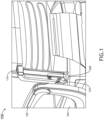
- FIG. 1 is a perspective view illustrating an aircraft seat 100, in accordance with one or more embodiments of the present disclosure.
- the aircraft seat 100 may include an arm rest 102 (e.g., which may be configured to support a user's arms) and a seat cushion 104 (e.g., which may be configured to support a user's legs).
- the aircraft seat 100 may comprise a seatback 110 (e.g., which may be configured to support a user's back) and a frame 120 (e.g., base, foundation, etc., connected to a floor of an aircraft).
- An HIC device 200 may be at a position between the seatback 110 and the frame 120.
- the HIC 200 may couple the seatback 110 and the frame 120 (for example, using one or more bolts, one or more screws, etc.), such that the seatback 110 is attached, affixed, or secured to the frame 120.
- the components of the HIC device 200 may comprise, for example, a metal (e.g., steel, aluminum, titanium, or an alloy thereof), however other high-strength metallic or composite materials (e.g., ceramic, fiber reinforced polymer, etc.) are also contemplated herein.
- FIG. 2 is a perspective view illustrating the HIC device 200, in accordance with one or more embodiments of the present disclosure.
- the HIC device 200 may comprise a first energy absorbing member 210, a second energy absorbing member 220, and a fuse link 230.
- the HIC device 200 may further include a shear pin mechanism (not shown) to further reduce a load experienced by a passenger.
- the first energy absorbing member 210 may be coupled to the seatback 110 of the aircraft seat 100 (for example, using a bolt passing through the void or cavity 215).
- the second energy absorbing member 220 may be coupled to the frame 120 of the aircraft seat 100 (for example, using a bolt passing through the void or cavity 225).
- the members 210 and 220 may each comprise a cylindrical shape or a rectangular-cuboid shape and may have a length (e.g., along a longitudinal axis) substantially greater than a width or thickness.
- the members 210 and 220 may include one or more curved surfaces and/or bends.
- the member 220 includes an energy absorbing appendage 250 having a tapered shape.
- the appendage 250 may be configured to press against the member 210 (e.g., causing the appendage to deform), which may further reduce a load experienced by a passenger during or after a dynamic event.
- the fuse link 230 may be partially or completely encapsulated by the first energy absorbing member 210 and the second energy absorbing member 220.
- the fuse link 230 may be configured to couple the first energy absorbing member 210 to the second energy absorbing member 220, and may be manufactured so that the fuse link 230 fits snugly between the members 210 and 220.
- the fuse link 230 is attached, affixed, or secured to the members 210 and 220 using an adhesive (e.g., glue).
- the fuse link 230 may be configured to break (i.e., fracture, snap, etc.).
- the breaking of the fuse link 230 may enable the first member 210 and the second member 220 to rotate around an axis 240 (e.g., an axis passing through or near a center of the HIC device 200).
- the energy absorbing member 210, the energy absorbing member 220, and the fuse link 230 are capable of absorbing a breakover energy associated with the seatback 110 during a dynamic event, and restricting a velocity of the seatback 110 during the dynamic event.
- a thickness of a middle portion of the fuse link 230 may be smaller than thicknesses of the side portions of the fuse link 230.
- the thickness of the middle portion of the fuse link 230 may be adjusted (e.g., during the time of manufacture) to change the threshold load associated with the breaking or fracture of the fuse link 230.
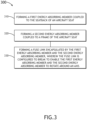
- FIG. 3 is a flowchart illustrating a method 300 of manufacturing an HIC device, in accordance with one or more embodiments of the present disclosure.
- the HIC device may be similar or identical to the HIC device 200 described with respect to FIGS. 1-2 .
- the components of the HIC device 200 may be formed using additive manufacturing (for example, 3D printing by stereolithography [SLA]), injection molding, and/or by milling or machining, etc.
- a first energy absorbing member is formed.
- the first energy absorbing member may be configured to couple to the seatback of an aircraft seat.
- a second energy absorbing member is formed.
- the second energy absorbing member may be configured to couple to a frame of an aircraft seat.
- a fuse link is formed.
- the fuse link may be configured to be encapsulated by the first energy absorbing member and the second energy absorbing member, and may be configured to couple the first energy absorbing member to the second energy absorbing member.
- length may be construed as the largest dimension of a given 3-dimensional structure or feature.
- width may be construed as the second largest dimension of a given 3-dimensional structure or feature.
- thickness may be construed as a smallest dimension of a given 3-dimensional structure or feature.
Landscapes
- Engineering & Computer Science (AREA)
- Aviation & Aerospace Engineering (AREA)
- Transportation (AREA)
- Mechanical Engineering (AREA)
- Seats For Vehicles (AREA)
- Vibration Dampers (AREA)
Abstract
Description
- The present application relates to a head impact criteria (HIC) device for a controlling a breakover rate of a seatback of an aircraft seat. The present application also relates to a method of manufacturing a head impact criteria (HIC) device for a controlling a breakover rate of a seatback of an aircraft seat.
- Aircraft seating configurations may provide for a seatback capable of breaking over during an impact event (e.g., accident or crash). For example, a passenger seat may broadly comprise a bottom chassis (upon which the passenger sits) and a seatback supporting the passenger's upper body, the rear of which seatback may face a second passenger sitting directly behind the passenger occupying the seat. The seatback can comprise, for example, a tray table assembly, tablet holder, literature pocket, display screen and console, or any combination of these components. In the event of a crash, rapid deceleration, emergency landing, or other similar impact event, the second passenger's head may be driven forward into the seatback. The seatback may then pivot, or break over, to a full breakover position at a predetermined angle with respect to the bottom chassis. Seatback breakover can mitigate head and/or neck injuries to the second passenger due to a head impact with the seatback.
- However, if the seatback breaks freely from the upright position to the full breakover position without any regulation of breakover speed, the resulting disparity in velocity between the seatback and the head of the second passenger may increase, rather than decrease, head injury and neck injury criteria (HIC, NIC) and lead to preventable egress damage which may impede passenger egress from the aircraft.
- According to an aspect, there is provided a head impact criteria (HIC) device for a controlling a breakover rate of a seatback of an aircraft seat as recited in claim 1. Further, optional, features are recited in each of claims 2 to 9.
- According to an aspect, there is provided a method of manufacturing a head impact criteria (HIC) device for a controlling a breakover rate of a seatback of an aircraft seat as recited in claim 10. Further, optional, features are recited in each of claims 2 to 9.
- A head impact criteria (HIC) device for a controlling a breakover rate of a seatback of an aircraft seat is disclosed in accordance with one or more illustrative embodiments of the present disclosure. In one illustrative embodiment, the device comprises a first energy absorbing member coupled to the seatback of the aircraft seat. In another illustrative embodiment, the device comprises a second energy absorbing member coupled to a frame of the aircraft seat. In another illustrative embodiment, the device comprises a fuse link encapsulated by the first energy absorbing member and the second energy absorbing member, and configured to couple the first energy absorbing member to the second energy absorbing member. The first energy absorbing member, the second energy absorbing member, and the fuse link are capable of transmitting a breakover energy associated with the seatback during a dynamic event. The first energy absorbing member and the second energy absorbing member are configured to rotate around a same axis. In response to the HIC device being subjected to a load above a threshold load associated with the dynamic event, the fuse link breaks, and the breaking of the fuse link enables the first energy absorbing member and the second energy absorbing member to rotate around the axis. A method of manufacturing the HIC device is also disclosed.
- It is to be understood that both the foregoing general description and the following detailed description are exemplary and explanatory only and are not necessarily restrictive of the invention as claimed. The accompanying drawings, which are incorporated in and constitute a part of the specification, illustrate embodiments of the invention and together with the general description, serve to explain the principles of the invention.
- The numerous advantages of the disclosure may be better understood by those skilled in the art by reference to the accompanying figures in which:
-
FIG. 1 is a perspective view illustrating an aircraft seat, in accordance with one or more embodiments of the present disclosure; -
FIG. 2 is a perspective view illustrating an HIC device for controlling a breakover rate of a seatback of an aircraft seat, in accordance with one or more embodiments of the present disclosure; and -
FIG. 3 is a flowchart illustrating a method of manufacturing an HIC device, in accordance with one or more embodiments of the present disclosure. - Before explaining at least one embodiment of the inventive concepts disclosed herein in detail, it is to be understood that the inventive concepts are not limited in their application to the details of construction and the arrangement of the components or steps or methodologies set forth in the following description or illustrated in the drawings. In the following detailed description of embodiments of the present disclosure, numerous specific details are set forth in order to provide a more thorough understanding of the inventive concepts. However, it will be apparent to one of ordinary skill in the art having the benefit of the present disclosure that the inventive concepts disclosed herein may be practiced without these specific details. In other instances, well-known features may not be described in detail to avoid unnecessarily complicating the present disclosure. The inventive concepts disclosed herein are capable of other embodiments or of being practiced or carried out in various ways. Also, it is to be understood that the phraseology and terminology employed herein is for the purpose of description and should not be regarded as limiting.
- As used herein a letter following a reference numeral is intended to reference an embodiment of the feature or element that may be similar, but not necessarily identical, to a previously described element or feature bearing the same reference numeral (e.g., 1, 1a, 1b). Such shorthand notations are used for purposes of convenience only, and should not be construed to limit the inventive concepts disclosed herein in any way unless expressly stated to the contrary. Further, unless expressly stated to the contrary, "or" refers to an inclusive or and not to an exclusive or. For example, a condition A or B is satisfied by any one of the following: A is true (or present) and B is false (or not present), A is false (or not present) and B is true (or present), and both A and B are true (or present). In addition, use of the "a" or "an" are employed to describe elements and components of embodiments of the present inventive concepts. This is done merely for convenience and to give a general sense of the inventive concepts, and "a" and "an" are intended to include one or at least one and the singular also includes the plural unless it is obvious that it is meant otherwise.
- Finally, as used herein any reference to "one embodiment" or "some embodiments" means that a particular element, feature, structure, or characteristic described in connection with the embodiment is included in at least one embodiment of the inventive concepts disclosed herein. The appearances of the phrase "in some embodiments" in various places in the specification are not necessarily all referring to the same embodiment, and embodiments of the inventive concepts disclosed may include one or more of the features expressly described or inherently present herein, or any combination or sub-combination of two or more such features, along with any other features which may not necessarily be expressly described or inherently present in the present disclosure.
- Embodiments of the present disclosure are directed to a head impact criterion (HIC) device and a method of manufacturing the same. The HIC device is easy to fine-tune and affordable. The HIC device enables a seatback to break away during a HIC event and thus reduce the impact loads experienced by the passenger. The present HIC device uses two adjacent energy absorbing members rotating about the same axis (e.g., like scissors or pliers). The energy absorbing members are coupled together by a fuse link (e.g., break-away member). In response to the HIC device being subjected to a load (e.g., above a threshold load), the fuse link breaks which enables the two energy absorbing members to rotate relative to each other (which may transfer rotational kinetic energy associated with the seatback to the energy absorbing members). One energy absorbing member may include an appendage that, by pressing against the other energy absorbing member, further reduces loads experienced by a passenger. The fuse link may be manufactured as a sheet metal part that is easily modifiable (e.g., so that the performance of the system can be tuned for the requirements of the specific system).
-
FIG. 1 is a perspective view illustrating anaircraft seat 100, in accordance with one or more embodiments of the present disclosure. Theaircraft seat 100 may include an arm rest 102 (e.g., which may be configured to support a user's arms) and a seat cushion 104 (e.g., which may be configured to support a user's legs). Theaircraft seat 100 may comprise a seatback 110 (e.g., which may be configured to support a user's back) and a frame 120 (e.g., base, foundation, etc., connected to a floor of an aircraft). - An
HIC device 200 may be at a position between theseatback 110 and theframe 120. The HIC 200 may couple theseatback 110 and the frame 120 (for example, using one or more bolts, one or more screws, etc.), such that theseatback 110 is attached, affixed, or secured to theframe 120. The components of theHIC device 200 may comprise, for example, a metal (e.g., steel, aluminum, titanium, or an alloy thereof), however other high-strength metallic or composite materials (e.g., ceramic, fiber reinforced polymer, etc.) are also contemplated herein. -
FIG. 2 is a perspective view illustrating theHIC device 200, in accordance with one or more embodiments of the present disclosure. TheHIC device 200 may comprise a firstenergy absorbing member 210, a secondenergy absorbing member 220, and afuse link 230. In some embodiments, theHIC device 200 may further include a shear pin mechanism (not shown) to further reduce a load experienced by a passenger. - The first
energy absorbing member 210 may be coupled to theseatback 110 of the aircraft seat 100 (for example, using a bolt passing through the void or cavity 215). The secondenergy absorbing member 220 may be coupled to theframe 120 of the aircraft seat 100 (for example, using a bolt passing through the void or cavity 225). Themembers - The
members FIG. 2 , themember 220 includes anenergy absorbing appendage 250 having a tapered shape. Theappendage 250 may be configured to press against the member 210 (e.g., causing the appendage to deform), which may further reduce a load experienced by a passenger during or after a dynamic event. - The
fuse link 230 may be partially or completely encapsulated by the firstenergy absorbing member 210 and the secondenergy absorbing member 220. Thefuse link 230 may be configured to couple the firstenergy absorbing member 210 to the secondenergy absorbing member 220, and may be manufactured so that thefuse link 230 fits snugly between themembers fuse link 230 is attached, affixed, or secured to themembers - In response to the
HIC device 200 being subjected to a load (i.e., a force measured in Newtons) above a threshold load associated with a dynamic event, thefuse link 230 may be configured to break (i.e., fracture, snap, etc.). The breaking of thefuse link 230 may enable thefirst member 210 and thesecond member 220 to rotate around an axis 240 (e.g., an axis passing through or near a center of the HIC device 200). In this way, theenergy absorbing member 210, theenergy absorbing member 220, and thefuse link 230 are capable of absorbing a breakover energy associated with theseatback 110 during a dynamic event, and restricting a velocity of theseatback 110 during the dynamic event. - As shown in
FIG. 2 , a thickness of a middle portion of thefuse link 230 may be smaller than thicknesses of the side portions of thefuse link 230. The thickness of the middle portion of thefuse link 230 may be adjusted (e.g., during the time of manufacture) to change the threshold load associated with the breaking or fracture of thefuse link 230. -
FIG. 3 is a flowchart illustrating amethod 300 of manufacturing an HIC device, in accordance with one or more embodiments of the present disclosure. The HIC device may be similar or identical to theHIC device 200 described with respect toFIGS. 1-2 . The components of theHIC device 200 may be formed using additive manufacturing (for example, 3D printing by stereolithography [SLA]), injection molding, and/or by milling or machining, etc. - At 310, a first energy absorbing member is formed. The first energy absorbing member may be configured to couple to the seatback of an aircraft seat.
- At 320, a second energy absorbing member is formed. The second energy absorbing member may be configured to couple to a frame of an aircraft seat.
- At 330, a fuse link is formed. The fuse link may be configured to be encapsulated by the first energy absorbing member and the second energy absorbing member, and may be configured to couple the first energy absorbing member to the second energy absorbing member.
- It is noted herein that the term "length" may be construed as the largest dimension of a given 3-dimensional structure or feature. The term "width" may be construed as the second largest dimension of a given 3-dimensional structure or feature. The term "thickness" may be construed as a smallest dimension of a given 3-dimensional structure or feature.
- It is believed that the present disclosure and many of its attendant advantages will be understood by the foregoing description, and it will be apparent that various changes may be made in the form, construction, and arrangement of the components without departing from the disclosed subject matter or without sacrificing all of its material advantages. The form described is merely explanatory, and it is the intention of the following claims to encompass and include such changes. Furthermore, it is to be understood that the invention is defined by the appended claims.
Claims (15)
- A head impact criteria (HIC) device for a controlling a breakover rate of a seatback of an aircraft seat, the HIC device comprising:a first energy absorbing member coupled to the seatback of the aircraft seat;a second energy absorbing member coupled to a frame of the aircraft seat;a fuse link encapsulated by the first energy absorbing member and the second energy absorbing member, and configured to couple the first energy absorbing member to the second energy absorbing member;wherein the first energy absorbing member, the second energy absorbing member, and the fuse link are configured to transmit a breakover energy associated with the seatback during a dynamic event,wherein the first energy absorbing member and the second energy absorbing member are configured to rotate around a same axis, andwherein, responsive to the HIC device being subjected to a load above a threshold load associated with the dynamic event, the fuse link breaks, the breaking of the fuse link enabling the first energy absorbing member and the second energy absorbing member to rotate around the axis.
- The HIC device of claim 1, wherein the breaking of the fuse link restricts a breakover velocity of the seatback and absorbs at least a portion of the breakover energy.
- The HIC device of claim 1 or 2, wherein the second energy absorbing member includes an energy absorbing appendage configured to reduce an impact of the first energy absorbing member during the dynamic event.
- The HIC device of claim 3, wherein the energy absorbing appendage has a tapered shape.
- The HIC device of claim 3 or 4, wherein, in use, the energy absorbing appendage is configured to contact the first energy absorbing member thereby causing the energy absorbing appendage to deform.
- The HIC device of any preceding claim, wherein at least one of the first energy absorbing member, the second energy absorbing member, and the fuse link comprise at least one of metal and composite materials.
- The HIC device of any preceding claim, wherein at least one of the first energy absorbing member and the second energy absorbing member has a cylindrical shape or a rectangular-cuboid shape having a greater length than width.
- The HIC device of any preceding claim, wherein the fuse link is positioned between the first energy absorbing member and the second energy absorbing member and is coupled to at least one of the first energy absorbing member and the second energy absorbing member.
- The HIC device of any preceding claim, wherein the fuse link has a substantially figure eight curved shape.
- A method of manufacturing a head impact criteria (HIC) device for a controlling a breakover rate of a seatback of an aircraft seat, the method comprising: forming a first energy absorbing member, the first energy absorbing member configured to couple to the seatback of the aircraft seat; forming a second energy absorbing member, the second energy absorbing member configured to couple to a frame of the aircraft seat;forming a fuse link, the fuse link configured to be encapsulated by the first energy absorbing member and the second energy absorbing member, and configured to couple the first energy absorbing member to the second energy absorbing member;wherein the first energy absorbing member, the second energy absorbing member, and the fuse link are configured to transmit a breakover energy associated with the seatback during a dynamic event,wherein the first energy absorbing member and the second energy absorbing member are configured to rotate around an axis, andwherein the fuse link is configured to break responsive to the HIC device being subjected to a load above a threshold load associated with the dynamic event, the breaking of the fuse link enabling the first energy absorbing member and the second energy absorbing member to rotate around the axis.
- The method of claim 10, wherein the breaking of the fuse link restricts a breakover velocity of the seatback and absorbs at least a portion of the breakover energy.
- The method of claim 10 or 11, wherein the second energy absorbing member includes an energy absorbing appendage configured to reduce an impact of the first energy absorbing member during the dynamic event, and wherein, in use, the energy absorbing appendage contacts the first energy absorbing member thereby causing the energy absorbing appendage to deform.
- The method of any of claims 10 to 12, wherein at least one of the first energy absorbing member and the second energy absorbing member are formed to have a cylindrical shape or a rectangular-cuboid shape having a greater length than width.
- The method of any of claims 10 to 13, further including positioning the fuse link between the first energy absorbing member and the second energy absorbing member and coupling the fuse link to at least one of the first energy absorbing member and the second energy absorbing member.
- The method of any of claims 10 to 14, wherein the fuse link is formed to have a substantially figure eight curved shape.
Applications Claiming Priority (1)
| Application Number | Priority Date | Filing Date | Title |
|---|---|---|---|
| US17/709,676 US11975840B2 (en) | 2022-03-31 | 2022-03-31 | Fuse link head impact criteria mitigating device |
Publications (2)
| Publication Number | Publication Date |
|---|---|
| EP4253239A1 true EP4253239A1 (en) | 2023-10-04 |
| EP4253239B1 EP4253239B1 (en) | 2025-04-23 |
Family
ID=85726928
Family Applications (1)
| Application Number | Title | Priority Date | Filing Date |
|---|---|---|---|
| EP23163870.1A Active EP4253239B1 (en) | 2022-03-31 | 2023-03-23 | Head impact criteria mitigating device including fuse link |
Country Status (2)
| Country | Link |
|---|---|
| US (1) | US11975840B2 (en) |
| EP (1) | EP4253239B1 (en) |
Families Citing this family (1)
| Publication number | Priority date | Publication date | Assignee | Title |
|---|---|---|---|---|
| US11975840B2 (en) * | 2022-03-31 | 2024-05-07 | B/E Aerospace, Inc. | Fuse link head impact criteria mitigating device |
Citations (3)
| Publication number | Priority date | Publication date | Assignee | Title |
|---|---|---|---|---|
| US20130049416A1 (en) * | 2009-12-11 | 2013-02-28 | Recaro Aircraft Seating Gmbh & Co. Kg | Seat device comprising an energy absorption unit |
| US20190031352A1 (en) * | 2017-07-25 | 2019-01-31 | Rockwell Collins, Inc. | Back Breakover Rate Control Device for HIC/NIJ Damage Reduction |
| EP3468833B1 (en) * | 2016-06-14 | 2021-09-01 | HAECO Americas, LLC | Seat system |
Family Cites Families (23)
| Publication number | Priority date | Publication date | Assignee | Title |
|---|---|---|---|---|
| US5320308A (en) * | 1991-12-04 | 1994-06-14 | Weber Aircraft, Inc. | Seatback breakover device |
| US5676421A (en) * | 1996-06-20 | 1997-10-14 | Lear Corporation | Vehicle seat energy absorbing mechanism |
| US6478256B1 (en) * | 2001-11-21 | 2002-11-12 | B E Aerospace, Inc. | Passenger seat with seat back breakover assembly and method |
| FR2931403B1 (en) * | 2008-05-22 | 2010-04-23 | Sicma Aero Seat | SHOCK ABSORPTION DEVICE AND SEAT HAVING SUCH A DEVICE |
| FR2950607B1 (en) * | 2009-09-30 | 2011-08-26 | Eurocopter France | SEAT FOR MOTORIZED FLYWHEELS, INCORPORATING MEANS FOR PROTECTING THE PASSENGER IN CASE OF CRASH |
| DE102012108352A1 (en) * | 2012-09-07 | 2014-03-13 | Recaro Aircraft Seating Gmbh & Co. Kg | Seat energy absorption device |
| US20140265474A1 (en) * | 2013-03-15 | 2014-09-18 | Lear Corporation | Seat recliner with breakaway connector rod |
| FR3006668B1 (en) * | 2013-06-10 | 2015-06-26 | Eurocopter France | ANTI CRASH AND AIRCRAFT SEAT |
| FR3014156B1 (en) * | 2013-12-03 | 2017-10-13 | Eads Sogerma | ENERGY ABSORBER FOR ANTICRASH SEAT AND ANTICRASH SEAT COMPRISING SUCH AN ENERGY ABSORBER |
| EP3277538B1 (en) * | 2015-03-31 | 2019-04-24 | Safran Seats USA LLC | Energy absorbing brackets for passenger seats |
| US10384783B2 (en) * | 2015-09-11 | 2019-08-20 | Safran Seats Usa Llc | Inertial breakover mechanism |
| US10676196B2 (en) * | 2016-01-21 | 2020-06-09 | Ami Industries, Inc. | Energy attenuating mounting foot for a cabin attendant seat |
| US9963234B2 (en) * | 2016-07-14 | 2018-05-08 | Ami Industries, Inc. | Energy absorbing assembly for aircraft seat |
| CN106741965A (en) | 2017-01-22 | 2017-05-31 | 湖北航宇嘉泰飞机设备有限公司 | For the energy absorption device of aero seat |
| FR3062610B1 (en) * | 2017-02-08 | 2019-04-19 | Expliseat | VEHICLE SEAT WITH TILTING BACKREST |
| US11059587B2 (en) * | 2017-05-31 | 2021-07-13 | B/E Aerospace, Inc. | Seat back decoupler mechanism |
| US10414501B2 (en) * | 2017-05-31 | 2019-09-17 | Rockwell Collins, Inc. | Seat back breakover with dynamically triggered actuator |
| US10696195B2 (en) * | 2017-11-15 | 2020-06-30 | Key Safety Systems, Inc. | Seat with energy Absorbing seatback |
| FR3080364B1 (en) * | 2018-04-19 | 2020-05-08 | Zodiac Seats France | SYSTEM FOR INERTIALLY UNLOCKING A SEAT BACK |
| US20200339264A1 (en) * | 2019-04-25 | 2020-10-29 | Crane Co. | Piston device for use with aircraft seat |
| US11279488B2 (en) * | 2020-02-20 | 2022-03-22 | B/E Aerospace, Inc. | Seat assembly with sacrificial backrest breakover feature |
| WO2021221652A1 (en) | 2020-04-30 | 2021-11-04 | Safran Seats Usa Llc | Passenger seat arrest mechanism |
| US11975840B2 (en) * | 2022-03-31 | 2024-05-07 | B/E Aerospace, Inc. | Fuse link head impact criteria mitigating device |
-
2022
- 2022-03-31 US US17/709,676 patent/US11975840B2/en active Active
-
2023
- 2023-03-23 EP EP23163870.1A patent/EP4253239B1/en active Active
Patent Citations (3)
| Publication number | Priority date | Publication date | Assignee | Title |
|---|---|---|---|---|
| US20130049416A1 (en) * | 2009-12-11 | 2013-02-28 | Recaro Aircraft Seating Gmbh & Co. Kg | Seat device comprising an energy absorption unit |
| EP3468833B1 (en) * | 2016-06-14 | 2021-09-01 | HAECO Americas, LLC | Seat system |
| US20190031352A1 (en) * | 2017-07-25 | 2019-01-31 | Rockwell Collins, Inc. | Back Breakover Rate Control Device for HIC/NIJ Damage Reduction |
Also Published As
| Publication number | Publication date |
|---|---|
| US11975840B2 (en) | 2024-05-07 |
| EP4253239B1 (en) | 2025-04-23 |
| US20230312096A1 (en) | 2023-10-05 |
Similar Documents
| Publication | Publication Date | Title |
|---|---|---|
| US3697128A (en) | Motor vehicle seat | |
| US9358903B2 (en) | Adjustment arrangement for a motor vehicle seat | |
| US7992934B2 (en) | Shock absorption device and seat including such a device | |
| EP3468833B1 (en) | Seat system | |
| EP3031724B1 (en) | A reclinable seat | |
| EP4253239A1 (en) | Head impact criteria mitigating device including fuse link | |
| US10227023B2 (en) | Energy absorbing brackets for passenger seats | |
| US20100102170A1 (en) | Energy absorbing seat | |
| CA2872536A1 (en) | Aircraft seat comprising a seat assembly | |
| JP5153794B2 (en) | Backrest support mechanism | |
| CN115027400A (en) | A safety device control method and device | |
| CN109689427B (en) | Linear adjuster for vehicle seat and vehicle seat | |
| WO2006093644A1 (en) | Energy absorption apparatus | |
| CN112166051B (en) | Seat back inertia unlocking system | |
| EP2229292A1 (en) | A seat comprising an anti- whiplash mechanism and a method for fitting such a mechanism to a seat | |
| EP4292877B1 (en) | Seat assembly | |
| US20030001413A1 (en) | Permanently deformable headrest for a vehicle seat and method of use | |
| JPH07187087A (en) | Seat under frame | |
| KR20150063697A (en) | Rear-end collision impact elevation equipment for car seat | |
| US6471295B1 (en) | Headrest arrangement for a vehicle seat | |
| KR102651038B1 (en) | Recliner device of car-seat for decreasing neck injury | |
| WO2002022399A2 (en) | Energy dissipating vehicle seat | |
| KR100482637B1 (en) | Automobile seat fixing structure for preventing injury of neck | |
| CN120589189A (en) | Aviation seat energy absorption structure and aviation seat | |
| CN117302519A (en) | Seat back including energy absorbing device |
Legal Events
| Date | Code | Title | Description |
|---|---|---|---|
| PUAI | Public reference made under article 153(3) epc to a published international application that has entered the european phase |
Free format text: ORIGINAL CODE: 0009012 |
|
| STAA | Information on the status of an ep patent application or granted ep patent |
Free format text: STATUS: THE APPLICATION HAS BEEN PUBLISHED |
|
| AK | Designated contracting states |
Kind code of ref document: A1 Designated state(s): AL AT BE BG CH CY CZ DE DK EE ES FI FR GB GR HR HU IE IS IT LI LT LU LV MC ME MK MT NL NO PL PT RO RS SE SI SK SM TR |
|
| STAA | Information on the status of an ep patent application or granted ep patent |
Free format text: STATUS: REQUEST FOR EXAMINATION WAS MADE |
|
| 17P | Request for examination filed |
Effective date: 20240404 |
|
| RBV | Designated contracting states (corrected) |
Designated state(s): AL AT BE BG CH CY CZ DE DK EE ES FI FR GB GR HR HU IE IS IT LI LT LU LV MC ME MK MT NL NO PL PT RO RS SE SI SK SM TR |
|
| GRAP | Despatch of communication of intention to grant a patent |
Free format text: ORIGINAL CODE: EPIDOSNIGR1 |
|
| STAA | Information on the status of an ep patent application or granted ep patent |
Free format text: STATUS: GRANT OF PATENT IS INTENDED |
|
| INTG | Intention to grant announced |
Effective date: 20241106 |
|
| GRAS | Grant fee paid |
Free format text: ORIGINAL CODE: EPIDOSNIGR3 |
|
| GRAA | (expected) grant |
Free format text: ORIGINAL CODE: 0009210 |
|
| STAA | Information on the status of an ep patent application or granted ep patent |
Free format text: STATUS: THE PATENT HAS BEEN GRANTED |
|
| AK | Designated contracting states |
Kind code of ref document: B1 Designated state(s): AL AT BE BG CH CY CZ DE DK EE ES FI FR GB GR HR HU IE IS IT LI LT LU LV MC ME MK MT NL NO PL PT RO RS SE SI SK SM TR |
|
| REG | Reference to a national code |
Ref country code: GB Ref legal event code: FG4D |
|
| REG | Reference to a national code |
Ref country code: CH Ref legal event code: EP |
|
| REG | Reference to a national code |
Ref country code: DE Ref legal event code: R096 Ref document number: 602023003009 Country of ref document: DE |
|
| REG | Reference to a national code |
Ref country code: IE Ref legal event code: FG4D |
|
| REG | Reference to a national code |
Ref country code: NL Ref legal event code: MP Effective date: 20250423 |
|
| PG25 | Lapsed in a contracting state [announced via postgrant information from national office to epo] |
Ref country code: NL Free format text: LAPSE BECAUSE OF FAILURE TO SUBMIT A TRANSLATION OF THE DESCRIPTION OR TO PAY THE FEE WITHIN THE PRESCRIBED TIME-LIMIT Effective date: 20250423 |
|
| REG | Reference to a national code |
Ref country code: AT Ref legal event code: MK05 Ref document number: 1787560 Country of ref document: AT Kind code of ref document: T Effective date: 20250423 |
|
| PG25 | Lapsed in a contracting state [announced via postgrant information from national office to epo] |
Ref country code: ES Free format text: LAPSE BECAUSE OF FAILURE TO SUBMIT A TRANSLATION OF THE DESCRIPTION OR TO PAY THE FEE WITHIN THE PRESCRIBED TIME-LIMIT Effective date: 20250423 Ref country code: FI Free format text: LAPSE BECAUSE OF FAILURE TO SUBMIT A TRANSLATION OF THE DESCRIPTION OR TO PAY THE FEE WITHIN THE PRESCRIBED TIME-LIMIT Effective date: 20250423 Ref country code: PT Free format text: LAPSE BECAUSE OF FAILURE TO SUBMIT A TRANSLATION OF THE DESCRIPTION OR TO PAY THE FEE WITHIN THE PRESCRIBED TIME-LIMIT Effective date: 20250825 |
|
| REG | Reference to a national code |
Ref country code: LT Ref legal event code: MG9D |
|
| PG25 | Lapsed in a contracting state [announced via postgrant information from national office to epo] |
Ref country code: NO Free format text: LAPSE BECAUSE OF FAILURE TO SUBMIT A TRANSLATION OF THE DESCRIPTION OR TO PAY THE FEE WITHIN THE PRESCRIBED TIME-LIMIT Effective date: 20250723 Ref country code: GR Free format text: LAPSE BECAUSE OF FAILURE TO SUBMIT A TRANSLATION OF THE DESCRIPTION OR TO PAY THE FEE WITHIN THE PRESCRIBED TIME-LIMIT Effective date: 20250724 |
|
| PG25 | Lapsed in a contracting state [announced via postgrant information from national office to epo] |
Ref country code: PL Free format text: LAPSE BECAUSE OF FAILURE TO SUBMIT A TRANSLATION OF THE DESCRIPTION OR TO PAY THE FEE WITHIN THE PRESCRIBED TIME-LIMIT Effective date: 20250423 |
|
| PG25 | Lapsed in a contracting state [announced via postgrant information from national office to epo] |
Ref country code: BG Free format text: LAPSE BECAUSE OF FAILURE TO SUBMIT A TRANSLATION OF THE DESCRIPTION OR TO PAY THE FEE WITHIN THE PRESCRIBED TIME-LIMIT Effective date: 20250423 |
|
| PG25 | Lapsed in a contracting state [announced via postgrant information from national office to epo] |
Ref country code: HR Free format text: LAPSE BECAUSE OF FAILURE TO SUBMIT A TRANSLATION OF THE DESCRIPTION OR TO PAY THE FEE WITHIN THE PRESCRIBED TIME-LIMIT Effective date: 20250423 |
|
| PG25 | Lapsed in a contracting state [announced via postgrant information from national office to epo] |
Ref country code: AT Free format text: LAPSE BECAUSE OF FAILURE TO SUBMIT A TRANSLATION OF THE DESCRIPTION OR TO PAY THE FEE WITHIN THE PRESCRIBED TIME-LIMIT Effective date: 20250423 |
|
| PG25 | Lapsed in a contracting state [announced via postgrant information from national office to epo] |
Ref country code: RS Free format text: LAPSE BECAUSE OF FAILURE TO SUBMIT A TRANSLATION OF THE DESCRIPTION OR TO PAY THE FEE WITHIN THE PRESCRIBED TIME-LIMIT Effective date: 20250723 |
|
| PG25 | Lapsed in a contracting state [announced via postgrant information from national office to epo] |
Ref country code: IS Free format text: LAPSE BECAUSE OF FAILURE TO SUBMIT A TRANSLATION OF THE DESCRIPTION OR TO PAY THE FEE WITHIN THE PRESCRIBED TIME-LIMIT Effective date: 20250823 |
|
| PG25 | Lapsed in a contracting state [announced via postgrant information from national office to epo] |
Ref country code: LV Free format text: LAPSE BECAUSE OF FAILURE TO SUBMIT A TRANSLATION OF THE DESCRIPTION OR TO PAY THE FEE WITHIN THE PRESCRIBED TIME-LIMIT Effective date: 20250423 |
|
| PG25 | Lapsed in a contracting state [announced via postgrant information from national office to epo] |
Ref country code: SM Free format text: LAPSE BECAUSE OF FAILURE TO SUBMIT A TRANSLATION OF THE DESCRIPTION OR TO PAY THE FEE WITHIN THE PRESCRIBED TIME-LIMIT Effective date: 20250423 Ref country code: DK Free format text: LAPSE BECAUSE OF FAILURE TO SUBMIT A TRANSLATION OF THE DESCRIPTION OR TO PAY THE FEE WITHIN THE PRESCRIBED TIME-LIMIT Effective date: 20250423 |
|
| PG25 | Lapsed in a contracting state [announced via postgrant information from national office to epo] |
Ref country code: CZ Free format text: LAPSE BECAUSE OF FAILURE TO SUBMIT A TRANSLATION OF THE DESCRIPTION OR TO PAY THE FEE WITHIN THE PRESCRIBED TIME-LIMIT Effective date: 20250423 |
|
| PG25 | Lapsed in a contracting state [announced via postgrant information from national office to epo] |
Ref country code: EE Free format text: LAPSE BECAUSE OF FAILURE TO SUBMIT A TRANSLATION OF THE DESCRIPTION OR TO PAY THE FEE WITHIN THE PRESCRIBED TIME-LIMIT Effective date: 20250423 |
|
| REG | Reference to a national code |
Ref country code: DE Ref legal event code: R097 Ref document number: 602023003009 Country of ref document: DE |
|
| PG25 | Lapsed in a contracting state [announced via postgrant information from national office to epo] |
Ref country code: SK Free format text: LAPSE BECAUSE OF FAILURE TO SUBMIT A TRANSLATION OF THE DESCRIPTION OR TO PAY THE FEE WITHIN THE PRESCRIBED TIME-LIMIT Effective date: 20250423 |
|
| PG25 | Lapsed in a contracting state [announced via postgrant information from national office to epo] |
Ref country code: IT Free format text: LAPSE BECAUSE OF FAILURE TO SUBMIT A TRANSLATION OF THE DESCRIPTION OR TO PAY THE FEE WITHIN THE PRESCRIBED TIME-LIMIT Effective date: 20250423 |
|
| PLBE | No opposition filed within time limit |
Free format text: ORIGINAL CODE: 0009261 |
|
| STAA | Information on the status of an ep patent application or granted ep patent |
Free format text: STATUS: NO OPPOSITION FILED WITHIN TIME LIMIT |
|
| REG | Reference to a national code |
Ref country code: CH Ref legal event code: L10 Free format text: ST27 STATUS EVENT CODE: U-0-0-L10-L00 (AS PROVIDED BY THE NATIONAL OFFICE) Effective date: 20260304 |
|
| 26N | No opposition filed |
Effective date: 20260126 |
|
| PGFP | Annual fee paid to national office [announced via postgrant information from national office to epo] |
Ref country code: DE Payment date: 20260219 Year of fee payment: 4 |
|
| PGFP | Annual fee paid to national office [announced via postgrant information from national office to epo] |
Ref country code: FR Payment date: 20260219 Year of fee payment: 4 |