EP4253226A2 - Dispositifs, systèmes et procédés associés de chargement de soute et procédés associés - Google Patents
Dispositifs, systèmes et procédés associés de chargement de soute et procédés associés Download PDFInfo
- Publication number
- EP4253226A2 EP4253226A2 EP23187875.2A EP23187875A EP4253226A2 EP 4253226 A2 EP4253226 A2 EP 4253226A2 EP 23187875 A EP23187875 A EP 23187875A EP 4253226 A2 EP4253226 A2 EP 4253226A2
- Authority
- EP
- European Patent Office
- Prior art keywords
- cargo
- pdu
- cargo hold
- clause
- roller
- Prior art date
- Legal status (The legal status is an assumption and is not a legal conclusion. Google has not performed a legal analysis and makes no representation as to the accuracy of the status listed.)
- Pending
Links
- 238000000034 method Methods 0.000 title claims abstract description 99
- 230000033001 locomotion Effects 0.000 claims abstract description 64
- 238000012423 maintenance Methods 0.000 claims description 13
- 230000007423 decrease Effects 0.000 claims description 7
- 238000012544 monitoring process Methods 0.000 claims description 6
- 238000009434 installation Methods 0.000 description 13
- 230000000712 assembly Effects 0.000 description 12
- 238000000429 assembly Methods 0.000 description 12
- 230000014759 maintenance of location Effects 0.000 description 5
- 238000005192 partition Methods 0.000 description 4
- 230000011218 segmentation Effects 0.000 description 4
- 230000036961 partial effect Effects 0.000 description 3
- 230000000007 visual effect Effects 0.000 description 3
- 230000008901 benefit Effects 0.000 description 2
- 238000010276 construction Methods 0.000 description 2
- 238000013461 design Methods 0.000 description 2
- 238000003780 insertion Methods 0.000 description 2
- 230000037431 insertion Effects 0.000 description 2
- 230000000670 limiting effect Effects 0.000 description 2
- 238000000926 separation method Methods 0.000 description 2
- XLYOFNOQVPJJNP-UHFFFAOYSA-N water Substances O XLYOFNOQVPJJNP-UHFFFAOYSA-N 0.000 description 2
- 230000003213 activating effect Effects 0.000 description 1
- 230000006978 adaptation Effects 0.000 description 1
- 238000004378 air conditioning Methods 0.000 description 1
- 230000004888 barrier function Effects 0.000 description 1
- 238000006243 chemical reaction Methods 0.000 description 1
- 238000004891 communication Methods 0.000 description 1
- 230000001143 conditioned effect Effects 0.000 description 1
- 239000000470 constituent Substances 0.000 description 1
- 238000013480 data collection Methods 0.000 description 1
- 230000001419 dependent effect Effects 0.000 description 1
- 238000009795 derivation Methods 0.000 description 1
- 230000000694 effects Effects 0.000 description 1
- 230000010006 flight Effects 0.000 description 1
- 239000013505 freshwater Substances 0.000 description 1
- 238000004519 manufacturing process Methods 0.000 description 1
- 239000000463 material Substances 0.000 description 1
- 238000012986 modification Methods 0.000 description 1
- 230000004048 modification Effects 0.000 description 1
- 230000002829 reductive effect Effects 0.000 description 1
- 230000000452 restraining effect Effects 0.000 description 1
- 230000002441 reversible effect Effects 0.000 description 1
- 230000035939 shock Effects 0.000 description 1
- 238000006467 substitution reaction Methods 0.000 description 1
- 239000002351 wastewater Substances 0.000 description 1
Images


Classifications
-
- B—PERFORMING OPERATIONS; TRANSPORTING
- B64—AIRCRAFT; AVIATION; COSMONAUTICS
- B64D—EQUIPMENT FOR FITTING IN OR TO AIRCRAFT; FLIGHT SUITS; PARACHUTES; ARRANGEMENT OR MOUNTING OF POWER PLANTS OR PROPULSION TRANSMISSIONS IN AIRCRAFT
- B64D9/00—Equipment for handling freight; Equipment for facilitating passenger embarkation or the like
- B64D9/003—Devices for retaining pallets or freight containers
-
- B—PERFORMING OPERATIONS; TRANSPORTING
- B64—AIRCRAFT; AVIATION; COSMONAUTICS
- B64C—AEROPLANES; HELICOPTERS
- B64C1/00—Fuselages; Constructional features common to fuselages, wings, stabilising surfaces or the like
- B64C1/18—Floors
- B64C1/20—Floors specially adapted for freight
-
- B—PERFORMING OPERATIONS; TRANSPORTING
- B64—AIRCRAFT; AVIATION; COSMONAUTICS
- B64D—EQUIPMENT FOR FITTING IN OR TO AIRCRAFT; FLIGHT SUITS; PARACHUTES; ARRANGEMENT OR MOUNTING OF POWER PLANTS OR PROPULSION TRANSMISSIONS IN AIRCRAFT
- B64D9/00—Equipment for handling freight; Equipment for facilitating passenger embarkation or the like
- B64D2009/006—Rollers or drives for pallets of freight containers, e.g. PDU
-
- B—PERFORMING OPERATIONS; TRANSPORTING
- B64—AIRCRAFT; AVIATION; COSMONAUTICS
- B64D—EQUIPMENT FOR FITTING IN OR TO AIRCRAFT; FLIGHT SUITS; PARACHUTES; ARRANGEMENT OR MOUNTING OF POWER PLANTS OR PROPULSION TRANSMISSIONS IN AIRCRAFT
- B64D45/00—Aircraft indicators or protectors not otherwise provided for
- B64D2045/0085—Devices for aircraft health monitoring, e.g. monitoring flutter or vibration
Definitions
- the disclosure herein relates to a system for moving loads, in particular within a cargo hold area of an aircraft, as well as a locking arrangement and transport vehicle for being used in the system. Moreover, the disclosure herein relates to a method of operating a respective system for moving loads (e.g., cargo containers) within a cargo hold area (e.g., of an aircraft).
- loads e.g., cargo containers
- a cargo hold area e.g., of an aircraft
- Cargo holds for cargo or passenger aircraft are normally used either for loading with cargo containers or for so-called bulk loading.
- cargo containers can be standardized containers or standardized pallets, sometimes referred to as Unit Load Devices (ULDs).
- ULDs Unit Load Devices
- rows of rollers are typically integrated into a cargo hold floor of the cargo hold which, depending on their specific design, may allow for a direction-dependent or direction-independent movement of the ULDs.
- a cargo hold comprising a respective row of rollers is shown, for example, in EP 1 527 993 B1 .
- the ULDs can be manually pushed and moved on the row of rollers.
- an electric drive system comprising Power Drive Units (PDUs) within or next to the row of rollers can be used for automatically moving the ULDs within the cargo hold.
- PDUs Power Drive Units
- cargo containers For loading with cargo containers, loading with often very bulky and heavy cargo containers is supported by specific components (e.g., rollers and various latches) that are installed in the hold. Amongst other tasks, these components here support the loading of cargo containers into the hold and the transport of the cargo containers inside the hold.
- cargo containers may be filled with several baggage items or freight of other types.
- the hold For bulk loading, the hold is loaded in a loose arrangement with the individual baggage items or freight items of other types to be transported.
- a latch for a cargo management system of a cargo hold comprising: a base plate configured for rigid attachment to a surface of the cargo hold; a latch head attached to the base plate and configured to prevent a movement of at least one cargo unit in a Y-direction and a Z-direction and to allow a movement of the at least one cargo unit in an X-direction; and a roller assembly attached to the base plate, opposite the latch head, and comprising at least one roller, the roller being configured to provide a vertical support to the at least one cargo unit in the Z-direction while allowing the movement of the at least one cargo unit in the X-direction.
- the at least one cargo unit is at least one unit load device (ULD).
- the latch head comprises a latch toe formed on an edge thereof, the latch toe being configured to engage against a base-latch heel formed in the base plate to secure the latch head within a latch head slot formed in the base plate.
- the base plate and the latch head comprise corresponding latch-base alignment features, including a protuberance on the base plate and a cavity formed in a bottom surface of the latch head, wherein, when the latch toe is engaged against the base-latch heel, the latch head is configured to pivotably rotate into an installed position, in which the protuberance is located within the cavity.
- the protuberance comprises a first through-hole formed through a thickness thereof, wherein the latch head comprises a second through-hole formed through a thickness thereof, wherein the first and second through-holes are substantially coaxial to each other when the cavity covers the protuberance, and wherein a pull pin is installed through the first and second through-holes to rigidly attach the latch head against the base plate in the installed position.
- the roller assembly comprises a frame having a roller toe formed on an edge thereof, the roller toe being configured to engage against a base-roller heel formed in the base plate, adjacent the base-latch heel, to secure the roller assembly to the base plate.
- the base plate and the roller assembly comprise corresponding roller-base alignment features, including a rib formed on the base plate and a recess formed in a bottom surface of the roller assembly, wherein, when the roller toe is engaged against the base-roller heel, the roller assembly is configured to pivotably rotate into an installed position, in which the rib is located within the recess.
- the roller-base alignment features comprise at least two slots formed in opposite sides, relative to the X-direction, of the base plate and at least two lateral tabs attached to the roller assembly, wherein each lateral tab is configured to engage within a corresponding slot of the at least two slots when the roller assembly is in the installed position.
- the at least two lateral tabs protrude from the roller base in the X-direction as a visual indicator of the partial engagement of the roller assembly over the base plate.
- the at least two slots comprise a keyed portion with which the corresponding lateral tabs engage to provide a retention force to prevent, along with the roller toe being engaged with the base-roller toe, separation of the roller assembly from the base plate in the Y-direction and/or the Z-direction.
- the roller-base alignment features are configured to prevent relative movement between the base plate and the roller assembly in the X-direction.
- a method of installing a latch in a cargo management system in a cargo hold comprising: attaching a base plate to a surface within the cargo hold; attaching a latch head to the base plate; and attaching a roller assembly to the base plate.
- attaching the latch head to the base plate comprises: engaging a latch toe against a base-latch heel of the base plate; pivoting the latch head down against the base plate into an installed position, such that a protuberance extending from the base plate towards and/or within a cavity of the latch head is covered; and inserting a pull pin through a first through-hole formed through the protuberance and a second through-hole formed through the latch head, which are substantially co-axial when the latch head is in the installed position.
- pivoting the latch head down against the base plate into the installed position prevents a movement of the latch head relative to the base plate in the X-direction and the Y-direction.
- attaching the roller assembly to the base plate comprises: engaging a roller toe against a base-roller heel of the base plate; and pivoting the latch head down against the base plate, over roller-base alignment features, comprising a rib and slots formed in the base plate and a recess and lateral tabs attached and/or formed in the roller assembly, such that the lateral tabs are located within a slot formed in the base plate.
- the rib and the recess are defined in a Y-Z plane.
- the roller-base alignment features prevent motion of the roller assembly in at least the X-direction relative to the base plate.
- the roller assembly allows a motion of a cargo unit through the Y-Z latch in a substantially frictionless manner.
- the cargo unit is a unit load device (ULD).
- a system for ensuring proper installation of components of a cargo management system within a cargo hold comprising: a plurality of cleats rigidly attached to a floor of the cargo hold, a first subset of the plurality of cleats comprising insets have a first shape, a second subset of the plurality of cleats comprising insets have a second shape, keys and rotatable fasteners attached to the components of the cargo management system, a first subset of the keys having the first shape and a second subset of the keys having the second shape, wherein the first subset of keys can only engage with the first subset of cleats and the second subset of keys can only engage with the second subset of cleats, and wherein the rotatable fasteners are configured for rotary movement to secure the components of the cargo management system to a respective cleat against which the rotary fastener is engaged.
- the first and second shapes are different shapes.
- the first and second shapes comprise geometric or amorphous shapes.
- the geometric shapes comprise one or more of a square, a triangle, a circle, a hexagon, a pentagon, and an hourglass.
- each of the cleats comprises a back, through which each cleat is rigidly attached to the cargo hold floor, at least two side walls on opposing lateral sides of the back, and a top surface, against which the rotatable fasteners are tightened to secure the components of the cargo management system to the cleat.
- At least one cleat has at least two insets formed through a thickness of the upper surface, into which a corresponding one of the keys can be inserted during installation of the components of the cargo management system.
- at least one cleat has a slot formed through a thickness of the upper surface, the slot being continuous and uninterrupted along a length of the cleat to bifurcate the upper surface of the cleat, thereby defining at least two flanges in the cleat.
- the rotatable fasteners are configured for insertion through the slot and to engage with an internal surface of the at least two flanges.
- the system comprises a tightener for each rotatable fastener, wherein the tightener is configured to clamp the flanges between the rotatable fastener and the component of the cargo management system to which the tightener is attached progressively tighter due to a rotary movement of the tightener.
- a width of the rotatable fasteners is less than a distance between the side walls of the cleat.
- a method of installing components of a cargo management system comprising: forming and/or providing insets having a first shape in an upper surface of a first subset of a plurality of cleats; forming and/or providing insets having a second shape in an upper surface of a second subset of the plurality of cleats; rigidly attaching a plurality of cleats to a floor of the cargo hold; attaching keys and rotatable fasteners to the components of the cargo management system, a first subset of the keys having the first shape and a second subset of the keys having the second shape; engaging the first subset of keys with the first subset of cleats; engaging the second subset of keys with the second subset of cleats; and rotating the rotatable fasteners are configured to secure the components of the cargo management system to a respective cleat against which the rotary fastener is engaged.
- the first and second shapes are different shapes.
- the first and second shapes comprise geometric or amorphous shapes.
- the geometric shapes comprise one or more of a square, a triangle, a circle, a hexagon, a pentagon, and an hourglass.
- each cleat comprises a back, through which each cleat is rigidly attached to the cargo hold floor, at least two side walls on opposing lateral sides of the back, and a top surface, against which the rotatable fasteners are tightened to secure the components of the cargo management system to the cleat.
- At least one cleat has at least two insets formed through a thickness of the upper surface, into which a corresponding one of the keys can be inserted during installation of the components of the cargo management system.
- at least one cleat has a slot formed through a thickness of the upper surface, the slot being continuous and uninterrupted along a length of the cleat to bifurcate the upper surface of the cleat, thereby defining at least two flanges in the cleat.
- the method comprises inserting the rotatable fasteners through the slot to engage with an internal surface of the at least two flanges.
- the method comprises progressively tightening the flanges between the rotatable fastener and the component of the cargo management system to which the tightener is attached by rotating the tightener in a first direction.
- a width of the rotatable fasteners is less than a distance between the side walls of the cleat.
- a power drive unit for transporting cargo units into, out of, and/or within a cargo hold
- the PDU comprising: a frame, by which the PDU is rigidly attached to a floor of the cargo hold; a body pivotably attached, via a hinge, at a first end of the frame; at least one drive roller attached at a second end of the body; and an actuator attached to the body and configured to cause a pivoting angular movement of the body, relative to the frame, about the hinge, wherein an angular position of the body relative to the frame is maintained by the actuator even upon a loss of power to the PDU, and wherein the body is configured to move between and including a retracted position and a deployed position.
- the cargo units are unit load devices (ULDs)
- ULDs unit load devices
- the at least one drive roller when the body is in the retracted position, the at least one drive roller is positioned entirely below a plane in which a bottom surface of the cargo units travels within the cargo hold so as to not be in contact with the cargo units and, when the body is in the deployed position, the at least one drive roller is positioned such that at least a portion thereof extends coincident to or beyond the plane in which the bottom surface of the cargo units travels within the cargo hold so that the at least one drive roller contacts the cargo units as the cargo units are transported within the cargo hold.
- the actuator comprises at least one roller having an eccentric shape.
- the eccentric shape is a substantially ovular shape having a first diameter and a second diameter, the first diameter being different from the second diameter.
- the first diameter has a size that is smaller than a distance measured from an axis of rotation of the actuator to a bottom surface of the body and the second diameter has a size that is larger than the distance measured from the axis of rotation of the actuator to the bottom surface of the body.
- an angular velocity of the body relative to the frame increases as the body moves from the retracted position to the deployed position.
- an angular velocity of the body relative to the frame decreases as the body moves from the deployed position to the retracted position.
- the PDU comprises a direct current (DC) brushless motor to reduce or eliminate inrush current and enable transport speed management of cargo units within the cargo hold.
- DC direct current
- a cargo management system comprising a plurality of the PDUs described hereinabove, at least one of the plurality of PDUs comprising a controlled area network (CAN) bus interface to control and communicate with a controller.
- the cargo units are unit load devices (ULDs).
- the at least one PDU is configured to provide predictive maintenance information, including roller health monitoring, operational cycles, and power events of the at least one PDU.
- the cargo management system comprises at least one proximity or position sensor adjacent the at least one PDU to detect a latched cargo unit in a stationary position over the PDU.
- the at least one PDU is configured for PIN programming via two PINs at a connector by providing different resistance values thereto.
- the at least one PDU is configured to provide maintenance and operational data via the CAN bus.
- the at least one PDU comprises at least first and second PDUs, the first PDU being installed within the cargo hold in a ball mat area, adjacent a cargo hold door, to transport a cargo unit in a transverse direction of the cargo hold and the second PDU being installed within the cargo hold in the ball mat area to transport a cargo unit in a longitudinal direction of the cargo hold.
- the body of the first PDU when one or more of the cargo units is being transported in the transverse direction, the body of the first PDU is in the deployed position and the body of the second PDU is in the retracted position. In some embodiments of the cargo management system, when one or more of the cargo units is being transported in the longitudinal direction, the body of the first PDU is in the retracted position and the body of the second PDU is in the deployed position. In some embodiments of the cargo management system, when cargo units are loaded within the cargo hold, the body of the first PDU is moved into or maintained in the deployed position to provide anti-roll-out functionality to a cargo unit within the cargo hold in the ball mat area adjacent the cargo hold door.
- a method of transporting cargo units into, out of, and/or within a cargo hold using at least one power drive unit comprising: rigidly attaching a frame of the at least one PDU a floor of the cargo hold; pivotably attaching a body of the at least one PDU, via a hinge, at a first end of the frame; attaching at least one drive roller at a second end of the body; driving a pivoting angular movement of the body, relative to the frame, about the hinge using an actuator attached to the body, the angular movement of the body being between and including a retracted position and a deployed position; and maintaining, upon a loss of power to the at least one PDU, an angular position of the body relative to the frame.
- PDU power drive unit
- the cargo units are unit load devices (ULDs).
- the at least one drive roller when the body is in the retracted position, the at least one drive roller is positioned entirely below a plane in which a bottom surface of the cargo units travels within the cargo hold so as to not be in contact with the cargo units and, when the body is in the deployed position, the at least one drive roller is positioned such that at least a portion thereof extends coincident to or beyond the plane in which the bottom surface of the cargo units travels within the cargo hold so that the at least one drive roller contacts the cargo units as the cargo units are transported within the cargo hold.
- the actuator comprises at least one roller having an eccentric shape.
- the eccentric shape is a substantially ovular shape having a first diameter and a second diameter, the first diameter being different from the second diameter.
- the first diameter has a size that is smaller than a distance measured from an axis of rotation of the actuator to a bottom surface of the body and the second diameter has a size that is larger than the distance measured from the axis of rotation of the actuator to the bottom surface of the body.
- an angular velocity of the body relative to the frame increases as the body moves from the retracted position to the deployed position.
- an angular velocity of the body relative to the frame decreases as the body moves from the deployed position to the retracted position.
- the at least one PDU comprises a direct current (DC) brushless motor to reduce or eliminate inrush current and enable transport speed management of cargo units within the cargo hold.
- the method comprises controlling the at least one PDU and communicating with a controller via a controlled area network (CAN) bus interface.
- the method comprises providing predictive maintenance information, including roller health monitoring, operational cycles, and power events of the at least one PDU to the controller via the CAN bus.
- the method comprises detecting, via at least one proximity or position sensor adjacent the at least one PDU, a latched cargo unit in a stationary position over the PDU.
- the method comprises PIN programming the at least one PDU via two PINs at a connector by providing different resistance values thereto. In some embodiments, the method comprises providing maintenance and operational data regarding the at least one PDU via the CAN bus. In some embodiments of the method, the at least one PDU comprises at least first and second PDUs, the method comprising transporting, using the first PDU, which is installed within the cargo hold in a ball mat area, adjacent a cargo hold door, a cargo unit in a transverse direction of the cargo hold and transporting, using the second PDU, which is installed within the cargo hold in the ball mat area, a cargo unit in a longitudinal direction of the cargo hold.
- the method comprises, when all cargo units are loaded within the cargo hold, moving or maintaining the body of the first PDU into the deployed position to provide anti-roll-out functionality to a cargo unit within the cargo hold in the ball mat area adjacent the cargo hold door.
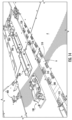
- Figure 1 is a schematic top view of the points of ingress and egress of an aircraft, generally designated 10 , for passengers, crew, cargo, and the like while the aircraft 10 is on the ground (e.g., at an airport terminal being resupplied during an aircraft turnaround between flights of the aircraft 10 ).
- the aircraft 10 is shown being connected to a plurality of example ground support units and systems.
- One or more cargo loaders, generally designated 24, can be placed next to the fuselage of the aircraft 10 to load cargo into the cargo hold of the aircraft 10 , either manually or in an automated manner.
- one or more (e.g., all) of the cargo loaders 24 can be bulk loaders and/or highlifters.
- one cargo loader 24 will be provided at an entry door to each segregated and/or partitioned portion of a cargo hold in an aircraft 10 where the cargo hold is not continuous along the length of the aircraft 10.
- a passenger loading bridge and/or stairway is used to allow passengers to walk from an airport terminal onto the aircraft 10.
- Galley service vehicle generally designated 26
- Galley service vehicle can be arranged at the fore and/or aft of the aircraft 10 to resupply the galleys of the aircraft 10.
- a water service vehicle, generally designated 28 can be connected to the aircraft 10 to remove water consumed during a previous flight and to supply fresh water for use by the passengers and/or crew of the aircraft 10 during a subsequent flight.
- a lavatory service vehicle, generally designated 30 is connected to remove wastewater generated by use of the lavatory of the aircraft 10.
- a stairway generally designated 32
- the aircraft 10 is connected to an electrical ground power unit, generally designated 34 , which supplies power to the aircraft 10 while, e.g., the engines of the aircraft 10 are powered down and/or disengaged.
- An air starting unit or air conditioning vehicle, generally designated 36 is connected to the aircraft to provide conditioned air to the interior of the aircraft for passenger and crew comfort while the aircraft 10 is on the ground with the aircraft engines and associated passenger/crew comfort systems turned off and/or disengaged.
- Figure 2 is a side view of an example aircraft, generally designated 10 , having at least one fore cargo hold, generally designated 40 , and primary and auxiliary aft cargo holds, generally designated 50 , 50A , respectively.
- Figure 3 shows an example embodiment of a fore cargo hold 40 which has been segmented, whether virtually, through use of attachment components to secure cargo only at particular locations within the fore cargo hold 40, and/or by physical partitions and/or segmentation of the fore cargo hold 40.
- the fore cargo hold 40 is subdivided into a first fore cargo area, generally designated 41, a second fore cargo area, generally designated 42, and a third fore cargo area, generally designated 43.
- any such physical partitions and/or segmentation within the fore cargo hold 40 is removable and/or configurable (e.g., not fixed in place) to allow for movement of cargo loaded at one end of the fore cargo hold 40, e.g., in first fore cargo area 41, to be moved into another cargo area within the fore cargo hold 40, whether the second fore cargo area 42 or the third fore cargo area 43.
- the fore cargo hold 40 may be subdivided into any desirable number and size areas (e.g., a plurality of such areas) as is desired based on the cargo configuration that the aircraft is intended to transport.
- Figure 4 shows an example embodiment of a primary aft cargo hold 50 which has been segmented, whether virtually, through use of attachment components to secure cargo only at particular locations within the primary aft cargo hold 50, and/or by physical partitions and/or segmentation of the primary aft cargo hold 50.
- the primary aft cargo hold 50 is subdivided into a first primary aft cargo area, generally designated 51, a second primary aft cargo area, generally designated 52, a third primary aft cargo area, generally designated 53, and a fourth primary aft cargo area, generally designated 54.
- any such physical partitions and/or segmentation within the primary aft cargo hold 50 is removable and/or configurable (e.g., not fixed in place) to allow for movement of cargo loaded at one end of the primary aft cargo hold 50, e.g., in first primary aft cargo area 51, to be moved into another cargo area within the primary aft cargo hold 50, whether the second primary aft cargo area 52, the third primary aft cargo area 53, or the fourth primary aft cargo area 54.
- the primary aft cargo hold 50 may be subdivided into any desirable number and size areas (e.g., a plurality of such areas) as is desired based on the cargo configuration that the aircraft is intended to transport.
- Figure 5 shows an example embodiment of an auxiliary aft cargo hold 50A, which can be physically segregated from, and have a separate loading door from, the primary aft cargo hold 50, and/or which can be physically connected and segregated, either virtually, as described elsewhere herein, or physically with a barrier, which can be permanent or, advantageously, removable.
- the auxiliary aft cargo hold 50A has only a single auxiliary aft cargo area, generally designated 55, but may be subdivided into any desirable number and size areas (e.g., a plurality of such areas) as is desired based on the cargo configuration that the aircraft is intended to transport.
- FIG 6 is an interior illustration of an example embodiment of an aircraft cargo hold 40E configured as a cargo aircraft (see 10C, Figure 7 ), having roller assemblies, generally designated 200, power drive units (PDUs), generally designated 100, X-Z latches, generally designated 300, and Y-Z latches, generally designated 400, arranged along the length of the cargo hold 40E and one or more ball mats 60 installed on the cargo floor 4 of the cargo hold 40E.
- PDUs power drive units
- X-Z latches generally designated 300
- Y-Z latches generally designated 400
- FIG. 7 is an exterior schematic view of the example cargo aircraft, generally designated 10C, of Figure 6 , in which the cargo aircraft 10C has only a minimal or no passenger area, the majority of the interior space of the cargo aircraft 10C.
- the cargo hold 40E is accessed through a cargo door 11 , by which a cargo unit 1 is loaded onto the aircraft via a loading ramp 12.
- Figure 8 schematically shows an example embodiment of a portion of a cargo hold 40E, showing the roller assemblies 200, PDUs 100, and ball mat 60 arranged at the entrance of the cargo hold 40E of such a cargo aircraft as is shown in Figures 6 and 7 .
- the cargo unit 1 is loaded via the loading ramp 12 onto the ball mat 60 and can then be driven in either direction along the longitudinal axis of the aircraft, the direction being generally designated T , such that the cargo unit 1 can be moved in the fore or aft direction within the cargo hold 40E.
- Figures 9 and 10 schematically show another example embodiment of a passenger aircraft 10 with a fore cargo hold 40 located underneath the passenger cabin 14 and in front of the wing 15 of the aircraft.
- a cargo loader 24 is provided to load the cargo units 1 into the fore cargo hold 40 through the cargo door 11 , then the cargo units 1 are moved along the length of the fore cargo hold 40 to a position designated so that all of the cargo units 1 can be loaded into the fore cargo hold 40.
- Figures 11 and 12 show another example embodiment of a cargo hold 40 , 50 , 50A , that has a floor 4 and is accessible through a cargo door 11. While the example embodiment shown is a cargo hold underneath a passenger cabin of an aircraft, the foregoing descriptions apply equally in a cargo hold (e.g., 40E , Figures 6 and 7 ) of a cargo aircraft (e.g., 10C , Figure 7 ). Adjacent the cargo door 11, a plurality of ball mats 60 are installed in and/or on the floor 4 of the cargo hold 40 , 50 , 50A.
- a main drive rail 6 is arranged along all or at least a portion of (e.g., a majority of) the length of the cargo hold 40, 50, 50A.
- PDUs, generally designated 100, roller assemblies, generally designated 200, and/or X-Z latches, generally designated 300, are arranged along the main drive rail 6.
- the cargo hold 40, 50, 50A may have a plurality of substantially parallel main drive rails 6, the term "substantially parallel” meaning that the main drive rails 6 are parallel to each other within a tolerance of the construction methods used in the construction of the cargo hold 40 , 50 , 50A.
- the PDUs 100 and/or X-Z latches 300 can be installed within the area where the ball mat(s) 60 are located.
- the PDUS 100 are configured to move the cargo (e.g., the cargo units 1, see Figures 9 and 10 ) along the length of the cargo hold 40, 50, 50A.
- the Y-Z latches are located along the lateral edges of the floor 4 of the cargo hold 40, 50, 50A so as to not block movement of the cargo along the length of the cargo hold 40, 50, 50A to and/or from a designated stowage position.
- the Y-Z latches 400 are therefore arranged at preset intervals and spaced apart from each other along the longitudinal axis of the aircraft.
- Each X-Z latch 300 can be spring-loaded and actuatable to prevent motion of the cargo against which the X-Z latch 300 is engaged in the X-direction (e.g., along the length of the aircraft) and the Z-direction (e.g., the vertical direction).
- Figure 13 shows an example embodiment of a main drive rail 6 installed in a cargo hold, such as is shown in Figures 11 and 12 , with a plurality of PDUs 100, roller assemblies 200, X-Z latches 300, Y-Z latches 400, and the like attached thereto in a designated configuration to facilitate movement and retention of cargo units (see, e.g., 1 in Figures 9 and 10 ) within the cargo hold in which the main drive rail 6 is installed.
- a cargo hold such as is shown in Figures 11 and 12
- PDUs 100, roller assemblies 200, X-Z latches 300, Y-Z latches 400, and the like attached thereto in a designated configuration to facilitate movement and retention of cargo units (see, e.g., 1 in Figures 9 and 10 ) within the cargo hold in which the main drive rail 6 is installed.
- the main drive rail 6 can extend up to, or into, the ball mat ( 60 , see Figures 11 and 12 ) or other suitable analogue located adjacent the entry to the cargo hold (e.g., at the cargo door 11 ), and is configured to transport ULDs, once they are loaded within the cargo hold, to a designated position within the cargo hold for transport to a destination by the aircraft.
- the roller assemblies 200 are configured to allow for substantially frictionless, at least compared to a sliding surface interface, movement of cargo along the length of the cargo hold, but are idler rollers, meaning that the rollers of the roller assemblies 200 are not driven, however, in some embodiments, one or more of the rollers of one or more of the roller assemblies 200 can be driven, rather than idler, rollers.
- the PDUs 100 are configured with a one or a plurality of driven rollers 140 that engages against a surface (e.g., a bottom surface) of the cargo to move the cargo by a frictional rotation of the driven roller 140 against the cargo.
- the Y-Z latches 400 are typically installed about the perimeter of the cargo hold and configured to engage with a laterally extending flange of the cargo unit (e.g.. of the ULD) passing through the cargo hold to prevent relative movement of the cargo within the cargo hold in the Y- and Z-directions.
- the X-Z latches 300 are typically installed along the main drive rail 6 at a designated spacing (e.g., pitch) based on the length of the ULDs (e.g., as measured in the X-direction) and are configured to engage with a flange of the cargo unit about which the latch is engaged to prevent relative movement of the cargo unit within the cargo hold in the X- and Z-directions.
- the X-Z latches 300 are typically spring-loaded and movable between and including deployed and retracted positions.
- the components of the X-Z latch are all located beneath the plane in which the cargo unit travels (e.g., beneath the top surface of the roller assemblies 200 and/or PDUs 100 ) so that the cargo units can pass over the X-Z latches 300 without any physical contact occurring between the cargo units and the X-Z latches 300.
- the X-Z latches In the deployed positions, the X-Z latches have a generally hooked shape (e.g., in the shape of an inverted L) that engage over (e.g., in the Z-direction) and against (e.g., in the X-direction) the flange of the cargo unit to prevent further movement of the cargo unit in the X- and Z-directions beyond the surfaces of the X-Z latch 300 where it contacts the flange of the cargo unit.
- a generally hooked shape e.g., in the shape of an inverted L
- Figure 14 is a partially exploded view of the main drive rail 6 shown in Figure 13 , showing the PDUs 100, roller assemblies 200, and X-Z latches 300 spaced vertically away from the main drive rail 6 , thereby showing the attachment cleats 500, 510, 520 used to define which of the PDUs 100, roller assemblies 200, and X-Z latches 300 can be installed based on an installation pattern of the cleats 500, 510, and 520 on the main drive rail 6.
- Each cleat 500, 510, and 520 has, as viewed cross-sectionally along the X-direction, a generally C-shape with a back portion attached to the cargo hold floor 4 at designated positions, side walls extending away from the lateral edges of the back portion in the Z-direction, perpendicular to the X-Y plane defining the cargo hold floor 4, and flanges that are spaced vertically apart from, but substantially parallel to, the cargo hold floor 4 and the back portion of the cleat 500, 510, and 520.
- the flanges are separated by a slot that is uninterrupted along the length of the cleat 500, 510, and 520.
- the flanges are in the form of a unitary top surface with inset shapes formed through a thickness (e.g., in the Z-direction) of the cleat 500, 510, and 520.
- These insets can be formed in any shape, including, for example, circle, triangle, square, and hourglass, as shown in Figures 24A-24D .
- Other examples can include pentagons, hexagons, or any shape, including non-geometric shapes.
- Other amorphous shapes are contemplated and envisioned in accordance with the disclosure herein as well.
- Figure 15 is a schematic illustration of an example embodiment of a PDU, generally designated 100, having a base 110 that is connectable to the main drive rail 6 within the cargo hold, a body 120 that is connected to the base at a pivoting connection point 130, and one or more (e.g., a plurality of) drive rollers 140 that are rotatably driven (e.g., on demand) about an axis.
- the body 120 of a PDU 100 is typically spring-loaded to be biased in the vertical direction, away from the cargo hold floor 4 , to ensure proper engagement of the drive roller(s) 140 against the bottom surface of the cargo unit being transported within the cargo hold.
- the PDU 100 is configured to rotate the drive roller(s) 140 in either direction to facilitate movement of the cargo units in both directions relative to the longitudinal orientation of the PDU 100, thereby enabling both loading and unloading of the cargo units into and out of the cargo hold of the aircraft.
- the PDU 100 has a DC brushless motor, controlled area network (CAN) bus interface, speed control management, bi-stable roller positioning, and predictive maintenance data collection.
- CAN controlled area network
- Such PDUs 100 can be used as a replacement for the door sill latches previously implemented to provide anti-roll-out functionality.
- the PDU 100 of Figures 16A and 16B has, to enable the bi-stable functionality, an integrated eccentrically-shaped actuator 160 (e.g., a roller) that can be controlled between at least two angular positions.
- an integrated eccentrically-shaped actuator 160 e.g., a roller
- the eccentric shape of the actuator 160 which has a substantially ovular shape, the angular position of the body 120, relative to the base 110 and the cargo hold floor 4 , can be changed merely by a rotational movement of the actuator 160.
- the actuator 160 can be a single roller, a plurality of rollers, one or more wheels, or any combination thereof or of any components capable of operating in such a manner.
- a first diameter D1 of the actuator 160 has a size such that it does not extend beyond the lower edge of the body 120 of the PDU 100 when the actuator 160 is in the first (e.g., retracted) position shown in Figure 16A , such that the drive roller 140 is in a position beneath a plane in which the bottom surface of the cargo units travels, so that the drive roller 140 is not in contact with the cargo units when the first diameter D1 of the actuator is perpendicular to the cargo hold floor 4 , as shown in Figure 16A .
- the actuator 160 Due to its eccentric shape, the actuator 160 has a second diameter D2 that is larger than a distance from the axis of rotation of the actuator 160 to the bottom surface/edge of the body 120 of the PDU 100, such that the body 120 is moved into a non-zero angular position relative to the cargo hold floor 4 when the second diameter D2 is oriented perpendicularly to the cargo hold floor 4 , as shown in Figure 16B .
- the PDU 100 In the deployed position, when the drive roller 140 is in contact with the cargo unit, the PDU 100 is able to control a movement (and rate of movement) of the cargo unit with which it is in contact; thus, the PDU 100 is capable of holding, stopping, or transporting a cargo unit within the cargo hold.
- Such holding functionality causes the PDU 100 to actively resist movement of the cargo unit from the position in which it is being held by preventing angular movement of the drive roller 140.
- Such stopping functionality brings the cargo unit to a stop (e.g., having zero velocity relative to the cargo hold in which it is located) but may not actively resist further movement of the cargo unit.
- Such transporting functionality causes a movement of the cargo unit within the cargo hold.
- the PDU 100 may be only partially deployed in some instances by only a partial rotation of the actuator 160 of less than 90° from the position in which the first diameter D1 is perpendicular to the cargo hold floor 4.
- the drive roller 140 In case of power loss, the drive roller 140 will remain safe in the last position (e.g., retracted or deployed, meaning that the actuator 160 will not return to a "home” or “rest” position).
- the drive roller 140 when in the deployed position, therefore provides a braking force to hold the cargo unit even during a power loss scenario, but the cargo unit may be manually moved (e.g., pushed or pulled) over the PDU 100 in such scenarios.
- the eccentric shape provides a smooth motion profile to the movement of the drive roller 140, relative to the cargo hold floor 4.
- the initial rotary movement of the actuator 160 initially produces a rate of travel of the drive roller 140 away from the cargo hold floor 4 that increases as the actuator 160 is progressively turned (e.g., assuming a constant angular velocity).
- a vertical velocity of the drive roller 140 from the retracted position to the deployed position increases, assuming the angular velocity of the actuator 160 remains constant, as the position of the drive roller 140 moves progressively further away from the retracted position.
- the PDU 100 is configured to perform predictive maintenance, for example, by detecting the condition of the material (e.g., rubber) of the drive roller 140 for roller health monitoring, operational cycles, and power events. Furthermore, one or more (e.g., a plurality of) proximity or position sensors 170A, 170B may be provided in or adjacent to the PDU 100 (e.g., fore and/or aft thereof) to detect a latched cargo unit in a position over, at least partially, the PDU 100.
- the PDU 100 is further configured for PIN programming via two PINs at a connector by providing different resistance values (e.g., by controlling a value of a variable resistor).
- a CAN bus interface can be provided to control the operation of the PDU 100 (e.g., the angular position of the actuator 160 and the angular velocity of the drive roller 140 ) and enable communication of the PDU 100 with a cargo management system control unit (e.g., a controller).
- the PDU 100 is configured to send maintenance and operational data via the CAN bus.
- the PDU 100 is configured to have a DC brushless motor to drive the actuator 160 and/or the drive roller 140 to reduce (e.g., eliminate) inrush current and enable transport speed management of the cargo units within the cargo hold by controlling the angular speed of the drive roller(s) 140.
- first PDU 100A is used for moving cargo units in a direction transverse to the fore/aft direction of the aircraft, this transverse direction being marked "IN/OUT”
- second PDU 100B is used for moving cargo units in the fore/aft direction, which is marked "FWD/AFT”.
- first PDU 100A In the area of the ball mat(s) 60 , for the transport of cargo units in the transverse direction, the drive roller of first PDU 100A has to be in the deployed position shown in Figure 16B and the drive roller of the second PDU 100B has to be in the retracted position shown in Figure 16A . In the area of the ball mat(s) 60, for the transport of cargo units in the fore/aft direction, the drive roller of first PDU 100A has to be in the retracted position and the drive roller of the second PDU 100B has to be in the deployed position. In the embodiment shown, if no command is given, transverse direction first PDU 100A will be commanded into the deployed position to provide the Anti-Roll-Out functionality that can be used in the place of cargo sill latches.
- the drive roller of each of the PDUs 100A, 100B, 100C will remain in their current respective positions, either in the deployed or retracted positions.
- the PDUs 100A, 100B, 100C are equipped with an actuator 160, such as an excenter.
- the PDUs 100A, 100B, 100C have a mechanical override function to bring the drive roller to the retracted position to be able to unload cargo units from the cargo hold in case of a loss of power.
- cleats 500, 510, 520, 530 can be used to ensure a proper orientation of a component, such as a PDU 100, such that the PDU 100 is not installed backwards, which may result in a reverse movement of the cargo unit within the cargo hold from that intended in such misconfigurations.
- a pair of circle cleats 500 is installed at a first position, spaced apart in the Y-direction, of the main drive rail 6 and a pair of square cleats 510 is installed at a second position, also spaced apart in the Y-direction, of the main drive rail 6.
- the specific shapes of the insets of the cleats used is generally immaterial and may be any combination, so long as they are "keyed" to only allow installation of the specified component of the cargo management system in only one orientation.
- Other components having no preferred directionality such as the roller assemblies 200, may be mounted using cleats, such as square cleats 510 in Figure 14 that are the same or different from each other at the respective opposing ends of the roller assembly, because there is no directionality needed to ensure proper functioning of such components.
- Fasteners 700 e.g., threadable rotary tightening members, such as screws, nuts, and the like
- each component e.g., PDUs 100 , roller assemblies 200, X-Z latches 300 , and the like
- rotatable fasteners 700 become rigidly (e.g., removably) engaged with the flanges 506 of the cleats 500 , 510 , 520 , 530, thereby allowing the component to be tightened securely in the designated position to allow safe and reliable operation of the cargo management system.
- Figure 19 shows a bottom view of an example PDU 100 having square keys 610 at the corners of a first end thereof and circle keys 600 at the corners of a second end thereof.
- the rotatable fasteners 700 can take any shape, but in the embodiment shown have that of an inverted "T" shape, extending vertically through the slot 508 and beneath the flanges 506 of the respective cleat 500, 510, 520, 530 to allow rotary movement of the rotatable fastener 700 without striking the cleat 500, 510, 520, 530 itself and also allowing engagement of the rotatable fastener 700 beneath the flanges 506 of the cleat 500 , 510 , 520 , 530 for retention of the component thereto.
- the rotary fastener 700 may have a length (e.g., a distance between ends of the "T" shape) that is greater than a width between the side walls 504 of the cleat, such that the rotatable fastener 700 cannot turn more than ⁇ 90° within the cleat 500 , 510, 520, 530 without contacting one or both of the side walls 504 , thereby allowing the rotary fastener 700 to be progressively turned to tighten (e.g., squeeze, as by a spring) the flanges 506 of the cleat 500 , 510 , 520 , 530 between the rotatable fastener 700 and the bottom side of the frame of the component being attached thereto, thus securing the component to the cleat 500, 510, 520, 530 in a designated configuration.
- a length e.g., a distance between ends of the "T" shape
- the keyed feature e.g., 600 , 610 , 620
- the keyed feature regardless of the shape, to have a thickness that is less than or, preferably, a same thickness as, that of the flanges 506 of the cleat 500, 510, 520, 530 against which it is engaged so that a rotary movement of the rotatable fastener 700 is not impeded by the keyed feature itself.
- Figure 20A shows square keys 610 and rotatable fasteners 700 on the underside of a roller assembly 200.
- the square keys 610 and rotatable fasteners 700 are configured to engage with the flanges 506 and square insets 515 (see also, Figure 24B ) of a square cleat 510, an example embodiment of which is shown in Figure 20B .
- the square cleat 500 has a base 502 with mounting hole(s) 503 formed through a thickness of the base 502 to secure the square cleat 510 to the cargo hold floor 4 using fasteners passing through the mounting hole(s) 503.
- the square cleat 510 has side walls 504 extending away from the base 502 out of the X-Y plane and connecting with flanges 506, the height of the side walls 504 defining a thickness of the slot 508 oriented along the length of the square cleat 510 in the X-direction.
- the flanges 506 and the slot 508 are shaped to form square insets 515 that are configured to ensure proper alignment of, and engagement with, a component having square keys (e.g., 610 , Figure 20A ) on a bottom surface thereof.
- the slot 508 is continuous and uninterrupted along the length of the square cleat 510.
- the square cleat 510 has two mounting holes 503 formed in the base 502 for fasteners (e.g., bolts, screws, rivets, and the like) to pass through to rigidly secure the square cleat 510 to the cargo hold floor 4. Any number of mounting holes 503 and fasteners may be used, in conjunction with pins formed on the back of the square cleat 510 to ensure proper alignment with a corresponding hole formed in the cargo hold floor 4 , to attach and align the cleat 500 along the cargo hold floor 4 in a designated configuration.
- fasteners e.g., bolts, screws, rivets, and the like
- Figure 20A shows the rotatable fasteners 700 in an engaged position, in which the square keys 610 of the roller assembly 200 could not be inserted into the square cleat 510, as the rotatable fastener 700 would contact the top surface of the flange 506 of the square cleat 510 , thereby preventing passage of the rotatable fasteners 700 beyond the flanges 506 and through the slot 508 unless the rotatable fastener 700 were to be rotated from the orientation shown to align with the slot 508 of the square cleat 510.
- FIG 21 shows an example embodiment of a triangle cleat 530.
- the triangle cleat 530 has a base 502 with mounting hole(s) 503 formed through a thickness of the base 502 to secure the triangle cleat 530 to the cargo hold floor 4 using fasteners passing through the mounting hole(s) 503.
- alignment features may be formed in a back side of the base 502 to aid in installation of the triangle cleat 530 to the cargo hold floor 4.
- the triangle cleat 530 has side walls 504 extending away from the base 502 out of the X-Y plane and connecting with flanges 506, the height of the side walls 504 defining a thickness of the slot 508 oriented along the length of the triangle cleat 530 in the X-direction.
- the flanges 506 and the slot 508 are shaped to form triangle insets 535 (see also, Figure 24C ) that are configured to ensure proper alignment of, and engagement with, a component having triangle keys on a bottom surface thereof.
- the rotary fasteners 700 of a component are configured to vertically pass through the slot 508 of the triangle cleat 530 and be twisted to secure the component to the triangle cleat 530.
- Figure 22A shows a bottom surface of a PDU 100 having circle keys 600 that are configured to engage with a circle cleat 500, an example embodiment of which is shown in Figure 22B .
- the circle cleat 500 has a base 502 with mounting hole(s) 503 formed through a thickness of the base 502 to secure the circle cleat 500 to the cargo hold floor 4 using fasteners passing through the mounting hole(s) 503.
- alignment features may be formed in a back side of the base 502 to aid in installation of the circle cleat 500 to the cargo hold floor 4.
- the circle cleat 500 has side walls 504 extending away from the base 502 out of the X-Y plane and connecting with flanges 506 , the height of the side walls 504 defining a thickness of the slot 508 oriented along the length of the circle cleat 500 in the X-direction.
- the flanges 506 and the slot 508 are shaped to form circle insets 505 (see also, Figure 24A ) that are configured to ensure proper alignment of, and engagement with, a component having circle keys 600 on a bottom surface thereof.
- the rotary fasteners 700 of a component are configured to vertically pass through the slot 508 of the circle cleat 500 and be twisted to secure the component to the circle cleat 500.
- Figure 23A shows a bottom surface of an X-Z latch 300 having hourglass keys 620 and rotatable fasteners 700 attached thereto and extending from an underside of a base of the X-Z latch 300.
- the hourglass keys 620 and the rotatably fasteners 700 are configured to engage with an hourglass cleat 520 to secure the X-Z latch 300 to the hourglass cleat 520.
- An example embodiment of an hourglass cleat 520 is shown in Figure 23B .
- the hourglass cleat 520 has a base 502 with mounting hole(s) 503 formed through a thickness of the base 502 to secure the hourglass cleat 520 to the cargo hold floor 4 using fasteners passing through the mounting hole(s) 503.
- alignment features may be formed in a back side of the base 502 to aid in installation of the hourglass cleat 520 to the cargo hold floor 4.
- the hourglass cleat 520 has side walls 504 extending away from the base 502 out of the X-Y plane and connecting with flanges 506 , the height of the side walls 504 defining a thickness of the slot 508 oriented along the length of the hourglass cleat 520 in the X-direction.
- the flanges 506 and the slot 508 are shaped to form hourglass insets 525 (see also, Figure 24D ) that are configured to ensure proper alignment of, and engagement with, a component having hourglass keys 620 on a bottom surface thereof.
- the rotary fasteners 700 of a component are configured to vertically pass through the slot 508 of the hourglass cleat 520 and be twisted to secure the component to the hourglass cleat 520.
- a circle key cannot fit within a square inset, a triangle inset, or an hourglass inset
- a square key cannot fit within a circle inset, a triangle inset, or an hourglass inset
- a triangle key cannot fit within a circle inset, a square inset, or an hourglass inset
- an hourglass key cannot fit within a circle inset, a square inset, or a triangle inset.
- a method of installing components of a cargo management system comprising: forming and/or providing insets having a first shape in an upper surface of a first subset of a plurality of cleats; forming and/or providing insets having a second shape in an upper surface of a second subset of the plurality of cleats; rigidly attaching a plurality of cleats to a floor of the cargo hold; attaching keys and rotatable fasteners to the components of the cargo management system, a first subset of the keys having the first shape and a second subset of the keys having the second shape; engaging the first subset of keys with the first subset of cleats; engaging the second subset of keys with the second subset of cleats; and rotating the rotatable fasteners are configured to secure the components of the cargo management system to a respective cleat against which the rotary fastener is engaged.
- the first and second shapes are different shapes.
- the first and second shapes comprise geometric or amorphous shapes.
- the geometric shapes comprise one or more of a square, a triangle, a circle, a hexagon, a pentagon, and an hourglass.
- each cleat comprises a back, through which each cleat is rigidly attached to the cargo hold floor 4 , at least two side walls on opposing lateral sides of the back, and a top surface, against which the rotatable fasteners are tightened to secure the components of the cargo management system to the cleat.
- At least one cleat has at least two insets formed through a thickness of the upper surface, into which a corresponding one of the keys can be inserted during installation of the components of the cargo management system.
- at least one cleat has a slot formed through a thickness of the upper surface, the slot being continuous and uninterrupted along a length of the cleat to bifurcate the upper surface of the cleat, thereby defining at least two flanges in the cleat.
- the method comprises inserting the rotatable fasteners through the slot to engage with an internal surface of the at least two flanges.
- the method comprises progressively tightening the flanges between the rotatable fastener and the component of the cargo management system to which the tightener is attached by rotating the tightener in a first direction.
- a width of the rotatable fasteners is less than a distance between the side walls of the cleat.
- FIGs 25 through 30 show various aspects of a Y-Z latch, generally designated 400, according to an example embodiment.
- a base plate 410 is rigidly connected to the lateral sides 5 of the cargo hold.
- the base plate 410 has a latch head slot 424, which is configured to have a latch head 430 removably attached thereto, and/or a roller assembly slot 422, which is configured to have a roller assembly 480 removably attached thereto.
- the base plate 410 has an auxiliary slot 416 formed therein, which can be used to secure further features to the base plate 410.
- the latch head 430 has a lateral (e.g., Y-direction) stop surface 450 and a vertical (e.g., Z-direction) stop surface 440.
- the latch head 430 is configured to prevent lateral and vertical movement of the cargo unit within the cargo hold while allowing movement of the cargo unit in the X-direction along the length of the aircraft.
- the latch head 430 has a latch toe 432 that engages, as shown in Figure 26 , against a base-latch heel 412 formed in the base plate 410.
- the latch head 430 is secured within the latch head slot 422 to the base plate 410 by a pull pin 420.
- the base plate 410 has a protuberance 423 formed thereon, over which the latch head 430 is secured, by a cavity corresponding in size and position to that of the protuberance 423, by the pull pin 420
- the base plate 410 has a through-hole 421 extending through the protuberance 423 in the X-direction
- the latch head 430 has a passage 434 that, when the latch head 430 is fully installed over the base plate 410 , the through-hole 421 and the passage 434 are substantially coaxially aligned, within a manufacturing tolerance, and can be rigidly secured together by inserting the pull pin 420 through a first portion of the passage 434 , through the through-hole 421 , and through a second portion of the passage 434 , as shown in the example embodiment of Figures 25-30 .
- the roller assembly 480 comprises a roller 490 rotatably attached to a frame 482 of the roller assembly 480 to provide vertical support (e.g., in the Z-direction) to the cargo unit and substantially frictionless motion of the cargo unit in the X-direction along the length of the cargo hold.
- the roller assembly 480 has keyed alignment features that ensure that the roller assembly 480 cannot move relative to the base plate 410 in the X-direction.
- a roller toe 484 which is secured to the base plate 410 by a base-roller heel 414 formed in the base plate 410; a rib 428 formed along the length of the roller assembly slot 422 of the base plate 410 and a corresponding recess in the bottom surface of the roller assembly 480, which are both oriented so as to be substantially coplanar when installed together, extending in the Y-Z plane, substantially perpendicular to the X-direction; and lateral tabs 486 spaced apart on opposite sides of the roller assembly 480 in the X-direction, which fit into slots 426 formed on opposite sides of the base plate 410 in the X-direction.
- the lateral tabs 486 comprise protrusions that are configured to fit within a keyed portion of the slots 426 such that, when the roller assembly 480 is not fully engaged over the base plate 410 , the lateral tabs 486 protrude from the roller assembly 480 in the X-direction and serve as a visual indicator that the roller assembly 480 is not fully engaged with the base plate 410. Furthermore, the engagement of the lateral tabs 486 into the keyed portion of the slots 426 of the base plate 410 provides a retention force to prevent the roller assembly 480 from separating from the base plate 410 in the Z-direction due to normal maneuvers of the aircraft in configurations of the cargo hold where the Y-Z latch is not engaged with a cargo unit.
- the base plate 410 has a plurality of mounting holes 418 formed through a thickness thereof for rigidly attaching the base plate 410 to the inner surface of the cargo hold.
- Figure 29 shows an example embodiment of a second configuration of the Y-Z latch 400 , in which the roller assembly ( 480 , Figures 25-28 ) is omitted in embodiments of a cargo management system that incorporates fixed rollers 800 rigidly attached to the cargo hold floor 4.
- Figure 30 shows an exploded view of the Y-Z latch according to the embodiment shown in Figure 29 .
- Figures 31A and 31B illustrate how the roller assembly 480 and the latch head 430 can be attached to the base plate 410.
- the roller toe 484 of the roller assembly 480 is inserted against the base-roller heel 414 and the roller assembly 480 is then pivoted in the clockwise direction into the roller assembly slot 422 of the base plate 410 , as shown in Figure 31A , such that the roller-base alignment features ( 426 , 428 , 486 ) engage with each other to retain the roller assembly 480 against the base plate 410.
- the latch toe 432 of the latch head 430 is inserted against the base-latch heel 412 and the latch head 430 is then pivoted in the counterclockwise direction into the latch head slot 424 of the base plate 410 , as shown in Figure 31B , such that the pull pin 420 can be inserted through the through-hole 421 of the base plate 410 and the passage 434 of the latch head 430 to secure the latch head 430 to the base plate 410.
- the method comprises attaching the base plate within the cargo hold of an aircraft, attaching the latch head to the base plate, and, optionally, attaching the roller assembly to the base plate.
- attaching the latch head comprises engaging the latch toe against the base-latch heel of the base plate and pivoting the latch head down against the base plate, over the latch-base mounting feature (e.g., a protuberance extending from the base plate), and inserting the pull pin through a hole formed through the latch-base alignment feature and a through-hole formed through the latch head in the X-direction.
- the latch-base mounting feature e.g., a protuberance extending from the base plate
- the latch-base alignment feature is configured to prevent a movement of the latch head relative to the base plate in the X-direction and the Y-direction.
- the pull pin has a collar that is lockingly inserted around a narrowed portion to prevent removal of the pull pin without first removing the collar in a direction orthogonal to the direction of removal of the pull pin.
- attaching the roller assembly to the base plate comprises engaging the roller toe against the base-roller heel of the base plate and pivoting the latch head down against the base plate, over the roller-base alignment features, such that the lateral tabs are located within a slot formed in the base plate.
- the roller-base alignment features comprise a rib of the base plate and a corresponding recess in the bottom surface of the roller assembly, the rib and the recess being defined in the Y-Z plane, and the lateral tabs and keyed portion of the slots in the base plate.
- the roller-base alignment features prevent motion of the roller assembly in at least the X-direction relative to the base plate.
- the roller allows a motion of the cargo unit over/through the Y- Z latch in a substantially frictionless manner.
Landscapes
- Engineering & Computer Science (AREA)
- Aviation & Aerospace Engineering (AREA)
- Mechanical Engineering (AREA)
- Connection Of Plates (AREA)
- Warehouses Or Storage Devices (AREA)
- Fittings On The Vehicle Exterior For Carrying Loads, And Devices For Holding Or Mounting Articles (AREA)
- Automatic Assembly (AREA)
Applications Claiming Priority (5)
| Application Number | Priority Date | Filing Date | Title |
|---|---|---|---|
| US201862786736P | 2018-12-31 | 2018-12-31 | |
| US201862786718P | 2018-12-31 | 2018-12-31 | |
| US201862786747P | 2018-12-31 | 2018-12-31 | |
| PCT/IB2019/061236 WO2020141397A2 (fr) | 2018-12-31 | 2019-12-20 | Dispositifs, systèmes et procédés associés de chargement de soute et procédés associés |
| EP19839273.0A EP3906191B1 (fr) | 2018-12-31 | 2019-12-20 | Dispositifs, systèmes et procédés associés de chargement de soute et procédés associés |
Related Parent Applications (2)
| Application Number | Title | Priority Date | Filing Date |
|---|---|---|---|
| EP19839273.0A Division EP3906191B1 (fr) | 2018-12-31 | 2019-12-20 | Dispositifs, systèmes et procédés associés de chargement de soute et procédés associés |
| EP19839273.0A Division-Into EP3906191B1 (fr) | 2018-12-31 | 2019-12-20 | Dispositifs, systèmes et procédés associés de chargement de soute et procédés associés |
Publications (2)
| Publication Number | Publication Date |
|---|---|
| EP4253226A2 true EP4253226A2 (fr) | 2023-10-04 |
| EP4253226A3 EP4253226A3 (fr) | 2023-11-29 |
Family
ID=69177180
Family Applications (3)
| Application Number | Title | Priority Date | Filing Date |
|---|---|---|---|
| EP19839273.0A Active EP3906191B1 (fr) | 2018-12-31 | 2019-12-20 | Dispositifs, systèmes et procédés associés de chargement de soute et procédés associés |
| EP23187875.2A Pending EP4253226A3 (fr) | 2018-12-31 | 2019-12-20 | Dispositifs, systèmes et procédés associés de chargement de soute et procédés associés |
| EP23187872.9A Pending EP4253225A3 (fr) | 2018-12-31 | 2019-12-20 | Dispositifs, systèmes et procédés associés de chargement de soute et procédés associés |
Family Applications Before (1)
| Application Number | Title | Priority Date | Filing Date |
|---|---|---|---|
| EP19839273.0A Active EP3906191B1 (fr) | 2018-12-31 | 2019-12-20 | Dispositifs, systèmes et procédés associés de chargement de soute et procédés associés |
Family Applications After (1)
| Application Number | Title | Priority Date | Filing Date |
|---|---|---|---|
| EP23187872.9A Pending EP4253225A3 (fr) | 2018-12-31 | 2019-12-20 | Dispositifs, systèmes et procédés associés de chargement de soute et procédés associés |
Country Status (4)
| Country | Link |
|---|---|
| US (3) | US11807393B2 (fr) |
| EP (3) | EP3906191B1 (fr) |
| CN (1) | CN113260568A (fr) |
| WO (1) | WO2020141397A2 (fr) |
Families Citing this family (3)
| Publication number | Priority date | Publication date | Assignee | Title |
|---|---|---|---|---|
| US11511981B2 (en) | 2020-09-01 | 2022-11-29 | Urbineer Inc | Robotic powered cargo handling system |
| US20220281603A1 (en) * | 2021-03-08 | 2022-09-08 | Ancra International Llc | Cargo system having bulk and transport configurations |
| DE102021112558A1 (de) * | 2021-05-14 | 2022-11-17 | Telair International Gmbh | Frachtfördersystem, Flugzeug und Verfahren zur Bereitstellung eines verkabelten Frachtfördersystems |
Citations (1)
| Publication number | Priority date | Publication date | Assignee | Title |
|---|---|---|---|---|
| EP1527993B1 (fr) | 2003-11-03 | 2009-02-11 | Telair International GmbH | Convoyeur pour une soute d'avion |
Family Cites Families (21)
| Publication number | Priority date | Publication date | Assignee | Title |
|---|---|---|---|---|
| US3241501A (en) * | 1964-01-08 | 1966-03-22 | Aid Corp | Hold-down device |
| US3698539A (en) * | 1971-07-06 | 1972-10-17 | Western Gear Corp | Torque controlled power roller for conveyor system |
| DE4102424C3 (de) * | 1991-01-28 | 2000-08-24 | Telair Int Gmbh | Antriebsrolleneinheit |
| DE4212694C2 (de) * | 1992-04-16 | 1995-09-21 | Daimler Benz Aerospace Airbus | Vorrichtung zur Verriegelung |
| US5267709A (en) * | 1992-05-15 | 1993-12-07 | Lucas Western, Inc. | Variable power conveyance apparatus |
| DE9409059U1 (de) * | 1994-06-03 | 1994-08-11 | Wuellhorst Gmbh & Co Kg | Profilleiste für Laderaumböden von Transportfahrzeugen |
| US5984615A (en) * | 1996-03-04 | 1999-11-16 | Sundseth; Jarl Gailon | Roller drive unit |
| US5871318A (en) * | 1997-11-12 | 1999-02-16 | Be Aerospace, Inc. | Quick-release track fastener |
| WO2002079071A2 (fr) * | 2001-03-29 | 2002-10-10 | Ancra International Llc | Unite d'entrainement de fret electrique |
| US6557800B2 (en) * | 2001-09-26 | 2003-05-06 | The Boeing Company | Cargo handling system for aircraft compartments |
| DE10212123B4 (de) * | 2002-03-19 | 2008-10-30 | Telair International Gmbh | Frachtladesystem in einem Laderaum eines Flugzeugs |
| ZA200508299B (en) * | 2003-05-02 | 2007-01-31 | Ancra Int Llc | Steerable/retractable cargo power drive unit |
| DE102004022551B4 (de) * | 2004-05-05 | 2006-02-09 | Hoffmann Air Cargo Equipment Gmbh | Adapter für eine Befestigungsschiene, System aus Befestigungsschiene und Adapter, Transportpalette, Befestigungseinrichtung und Sicherungsmittel |
| DE102005030058A1 (de) * | 2005-06-27 | 2007-01-04 | Wittenstein Ag | Vorrichtung zum Transportieren von Frachtgut |
| DE202006007845U1 (de) * | 2006-05-16 | 2006-09-07 | Allsafe Jungfalk Gmbh & Co. Kg | Vorrichtung zum Festlegen eines Gegenstandes |
| US7721875B2 (en) * | 2007-06-14 | 2010-05-25 | Goodrich Corporation | Power drive unit with eccentric roller lift system |
| US8585334B2 (en) * | 2012-04-03 | 2013-11-19 | Ancra International Llc | Attenuating cargo restraint device |
| EP2813429B1 (fr) | 2013-06-13 | 2016-09-14 | Airbus Operations GmbH | Unité d'entraînement et plancher de soute à fret d'aéronef avec unités d'entraînement |
| DE102015104230B4 (de) * | 2015-03-20 | 2017-07-13 | Telair International Gmbh | Montageeinrichtung |
| US9932112B1 (en) * | 2017-03-22 | 2018-04-03 | Goodrich Corporation | Cargo handling system and control method |
| US10214357B2 (en) * | 2017-06-13 | 2019-02-26 | Goodrich Corporation | Lift roller for power drive unit |
-
2019
- 2019-12-20 EP EP19839273.0A patent/EP3906191B1/fr active Active
- 2019-12-20 EP EP23187875.2A patent/EP4253226A3/fr active Pending
- 2019-12-20 WO PCT/IB2019/061236 patent/WO2020141397A2/fr unknown
- 2019-12-20 CN CN201980087484.9A patent/CN113260568A/zh active Pending
- 2019-12-20 EP EP23187872.9A patent/EP4253225A3/fr active Pending
-
2021
- 2021-06-29 US US17/362,052 patent/US11807393B2/en active Active
- 2021-06-29 US US17/361,934 patent/US20210354827A1/en active Pending
- 2021-06-29 US US17/361,999 patent/US11807392B2/en active Active
Patent Citations (1)
| Publication number | Priority date | Publication date | Assignee | Title |
|---|---|---|---|---|
| EP1527993B1 (fr) | 2003-11-03 | 2009-02-11 | Telair International GmbH | Convoyeur pour une soute d'avion |
Also Published As
| Publication number | Publication date |
|---|---|
| EP3906191A2 (fr) | 2021-11-10 |
| US11807392B2 (en) | 2023-11-07 |
| EP4253225A2 (fr) | 2023-10-04 |
| WO2020141397A3 (fr) | 2020-08-13 |
| US20210354827A1 (en) | 2021-11-18 |
| CN113260568A (zh) | 2021-08-13 |
| EP4253226A3 (fr) | 2023-11-29 |
| US11807393B2 (en) | 2023-11-07 |
| EP4253225A3 (fr) | 2023-11-29 |
| US20210354828A1 (en) | 2021-11-18 |
| US20210394905A1 (en) | 2021-12-23 |
| WO2020141397A2 (fr) | 2020-07-09 |
| EP3906191B1 (fr) | 2023-09-06 |
Similar Documents
| Publication | Publication Date | Title |
|---|---|---|
| US11807393B2 (en) | Bi-stable power drive unit (PDU) for a cargo hold loading and storage system and associated methods | |
| EP3345833B1 (fr) | Systèmes et procédés de manipulation de fret | |
| EP2962936B1 (fr) | Système et procédé d'installation d'équipement de test de vol | |
| US6557800B2 (en) | Cargo handling system for aircraft compartments | |
| EP2507128B1 (fr) | Plancher de soute d'avion, element fonctionnel a integrer dans un plancher de soute, element de guidage lateral, dispositif de fixation permettant d'induire un effort de traction et dispositif permettant de larguer des elements de cargaison | |
| US8864079B2 (en) | Aircraft cargo compartment container crane system | |
| EP2441668B1 (fr) | Système de manipulation de charge à profil bas | |
| US9975636B2 (en) | Cargo restraining assembly, cargo loading system and aircraft | |
| EP3848283B1 (fr) | Ensembles de retenue réglables | |
| US20110226899A1 (en) | Autonomous plane architecture for the transport and the replacement of propulsion engines | |
| US20190276148A1 (en) | Side guide, side guide group, cargo deck, aircraft | |
| US9630716B2 (en) | Cargo restraining barrier, cargo loading system and aircraft | |
| DE102008058425B4 (de) | System zum Unterbringen mindestens eines Gepäckstücks in einer Kabine eines Fahrzeugs | |
| GB2500767A (en) | System for loading passengers into a vehicle | |
| CN216969998U (zh) | 无人运输机 | |
| EP4296163A1 (fr) | Raccords pour système de manutention de fret d'aéronef convertible | |
| US11897629B2 (en) | Cargo handling system repositionable side guide | |
| EP3778394A1 (fr) | Ensemble de retenue pour système de chargement | |
| DE102020118477A1 (de) | Transport von Fracht in der Passagierkabine von Verkehrsflugzeugen |
Legal Events
| Date | Code | Title | Description |
|---|---|---|---|
| PUAI | Public reference made under article 153(3) epc to a published international application that has entered the european phase |
Free format text: ORIGINAL CODE: 0009012 |
|
| STAA | Information on the status of an ep patent application or granted ep patent |
Free format text: STATUS: THE APPLICATION HAS BEEN PUBLISHED |
|
| AC | Divisional application: reference to earlier application |
Ref document number: 3906191 Country of ref document: EP Kind code of ref document: P |
|
| AK | Designated contracting states |
Kind code of ref document: A2 Designated state(s): AL AT BE BG CH CY CZ DE DK EE ES FI FR GB GR HR HU IE IS IT LI LT LU LV MC MK MT NL NO PL PT RO RS SE SI SK SM TR |
|
| REG | Reference to a national code |
Ref country code: DE Ref legal event code: R079 Free format text: PREVIOUS MAIN CLASS: B64C0001200000 Ipc: B64D0009000000 |
|
| PUAL | Search report despatched |
Free format text: ORIGINAL CODE: 0009013 |
|
| AK | Designated contracting states |
Kind code of ref document: A3 Designated state(s): AL AT BE BG CH CY CZ DE DK EE ES FI FR GB GR HR HU IE IS IT LI LT LU LV MC MK MT NL NO PL PT RO RS SE SI SK SM TR |
|
| RIC1 | Information provided on ipc code assigned before grant |
Ipc: B64C 1/20 20060101ALI20231024BHEP Ipc: B64D 9/00 20060101AFI20231024BHEP |