EP4253144A1 - Vehiclular seat structure - Google Patents
Vehiclular seat structure Download PDFInfo
- Publication number
- EP4253144A1 EP4253144A1 EP23153895.0A EP23153895A EP4253144A1 EP 4253144 A1 EP4253144 A1 EP 4253144A1 EP 23153895 A EP23153895 A EP 23153895A EP 4253144 A1 EP4253144 A1 EP 4253144A1
- Authority
- EP
- European Patent Office
- Prior art keywords
- seat
- hole
- vehiclular
- ventilation
- frame
- Prior art date
- Legal status (The legal status is an assumption and is not a legal conclusion. Google has not performed a legal analysis and makes no representation as to the accuracy of the status listed.)
- Granted
Links
Images




Classifications
-
- B—PERFORMING OPERATIONS; TRANSPORTING
- B60—VEHICLES IN GENERAL
- B60N—SEATS SPECIALLY ADAPTED FOR VEHICLES; VEHICLE PASSENGER ACCOMMODATION NOT OTHERWISE PROVIDED FOR
- B60N2/00—Seats specially adapted for vehicles; Arrangement or mounting of seats in vehicles
- B60N2/56—Heating or ventilating devices
- B60N2/5607—Heating or ventilating devices characterised by convection
- B60N2/5621—Heating or ventilating devices characterised by convection by air
- B60N2/5628—Heating or ventilating devices characterised by convection by air coming from the vehicle ventilation system, e.g. air-conditioning system
-
- B—PERFORMING OPERATIONS; TRANSPORTING
- B60—VEHICLES IN GENERAL
- B60N—SEATS SPECIALLY ADAPTED FOR VEHICLES; VEHICLE PASSENGER ACCOMMODATION NOT OTHERWISE PROVIDED FOR
- B60N2/00—Seats specially adapted for vehicles; Arrangement or mounting of seats in vehicles
- B60N2/56—Heating or ventilating devices
- B60N2/5607—Heating or ventilating devices characterised by convection
- B60N2/5621—Heating or ventilating devices characterised by convection by air
- B60N2/5635—Heating or ventilating devices characterised by convection by air coming from the passenger compartment
-
- B—PERFORMING OPERATIONS; TRANSPORTING
- B60—VEHICLES IN GENERAL
- B60N—SEATS SPECIALLY ADAPTED FOR VEHICLES; VEHICLE PASSENGER ACCOMMODATION NOT OTHERWISE PROVIDED FOR
- B60N2/00—Seats specially adapted for vehicles; Arrangement or mounting of seats in vehicles
- B60N2/58—Seat coverings
Definitions
- the present invention relates to a vehiclular seat structure.
- a vehiclular seat with an air conditioning function that is capable of conditioning air around a seating surface of a seating portion and a seating surface of a seatback is known.
- a vehiclular seat with an air conditioning function includes ventilation portions (ventilation ports) provided in cushion materials forming the seating surfaces and a blower device (fan) at a position in communication with the ventilation portions.
- Patent Literature 1 discloses a vehiclular seat including a rear seat face air outlet provided in a back surface of a seatback on a front seat side.
- the vehiclular seat has a structure in which the rear seat face air outlet communicates with a back surface air passage through which conditioned air from an indoor air conditioning unit is guided and a blowing direction of the conditioned air to the rear seat side can be adjusted by a vertical adjustment louver provided at the rear seat face air outlet.
- Patent Literature 1 WO 2016/158472 A1
- the ventilation portion such as the rear seat face air outlet is provided in the back surface of the seatback on the front seat side in the conventional vehiclular seat structure as described above, the ventilation portion will be brought into a state in which the ventilation portion is exposed to the vehicle interior, is in view of an occupant in the rear seat, and thus degrades the appearance of the vehiclular seat, and ultimately the aesthetic appearance of the vehicle interior. Also, in a case in which the ventilation portion is installed to be exposed to the vehicle interior, it is necessary to make arrangements to prevent a load from concentrating on an article or the like when the article or the like comes into contact with the ventilation portion.
- the present invention has been made in view of the above points, and an object thereof is to provide a vehiclular seat structure capable of curbing concentration of a load on an article or the like when the article or the like comes into contact with a ventilation portion while avoiding exposure of the ventilation portion to a vehicle interior.
- an aspect of a vehiclular seat structure provides a vehiclular seat structure including: a cushion material that forms a seating surface; a blower device that conditions air around the seating surface, and a seat cover that covers the cushion material.
- the seat cover includes a ventilation portion that communicates with the blower device, and is formed at a position at which the ventilation portion covers a part different from the seating surface of the cushion material, the ventilation portion having air permeability, and a covering portion that is formed at a position at which the covering portion covers the ventilation portion from outside of the seat.
- the vehiclular seat structure of the present invention it is possible to curb concentration of a load on an article or the like when the article or the like comes into contact with the ventilation portion while avoiding exposure of the ventilation portion to the vehicle interior by providing the ventilation portion at the seat cover such that the ventilation portion is covered with the covering portion from the outside of the seat.
- the direction of the arrow Fr indicates a front side in a front-rear direction of a vehiclular seat.
- the "front portion (front end) and rear portion (rear end)" in the description of the embodiment corresponds to the front portion and the rear portion in the seat front-rear direction.
- the front side in the seat front-rear direction in the present embodiment corresponds to the front side in a vehicle front-rear direction.
- the direction of the arrow R and the direction of the arrow L indicate the right side and the left side when an occupant is seated in the vehiclular seat.
- the direction of the arrow U indicates the upper side.
- Figure 1 is a perspective view illustrating an appearance of a vehiclular seat 1 to which a structure according to the embodiment is applied.
- Figure 2 is a rear view of the vehiclular seat 1 in Figure 1 .
- Figure 2 illustrates a state in which a headrest 35 of the vehiclular seat 1 has been removed and a covering portion 332 of a seatback cover 33 has been lifted upward behind the seat.
- the covering portion 332 is brought into a state in which it covers the front side on the seat lower side as illustrated by the two-dotted dashed line in Figure 2 when the vehiclular seat 1 is used.
- the vehiclular seat 1 includes a seating portion 10 and a seatback 30.
- the seating portion 10 is a part where an occupant is seated.
- the seating portion 10 includes a seating portion frame 11, a seating portion cushion 12 that forms a seating surface, and a seating portion cover 13 that covers the seating portion cushion 12.
- the seatback 30 is a part extending upward from the rear portion of the seating portion 10 and is configured to support an upper body, in particular, of the occupant who is seated in the seating portion 10.
- the seatback 30 includes a seatback frame 31 ( Figure 4 , which will be described later), a seatback cushion 32 that forms the seating surface, a seatback cover 33 that covers the seatback cushion 32, a blower fan 34 that conditions air around the seating surface, and a headrest 35 that supports the head portion of the occupant.
- the seatback cushion 32 corresponds to the "cushion material” in the present invention
- the seatback cover 33 corresponds to the “seat cover” in the present invention
- the blower fan 34 corresponds to the "blower device” in the present invention.
- each member of the vehiclular seat 1 will be specifically described.
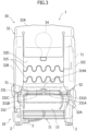
- Figure 3 is a rear view illustrating a state in which the seating portion cover 13 and the seatback cover 33 have been removed in the vehiclular seat 1 in Figure 2 .
- Figure 4 is a rear view illustrating a state in which the seating portion cushion 12 and the seatback cushion 32 have been removed in the vehiclular seat 1 in Figure 3 .
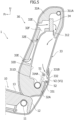
- Figure 5 is a sectional view seen from the arrow direction of the A-A line of Figure 2 .
- the seating portion frame 11 of the seating portion 10 configures a skeleton of the seating portion 10.
- a lower portion of the seating portion frame 11 has parts on both sides in the seat width direction movably attached to left and right seat rails 2 via traveling portions (not illustrated) ( Figures 1 to 4 ).
- the seat rails 2 are provided at a floor portion (not illustrated) in the vehicle interior and extend in the vehicle front-rear direction.
- the seating portion cushion 12 has elastic properties and is installed at an upper portion of the seating portion frame 11 ( Figures 1 to 3 and 5 ). An upper portion of the seating portion cushion 12 forms a seating surface where the occupant is seated.
- the seating portion cover 13 is a trim covering the seating portion cushion 12 from the upper side ( Figures 1 and 2 ).
- the seating portion cover 13 covers the upper portion (seating surface), the front portion, the rear portion, and both left and right side portions of the seating portion cushion 12.
- the seatback frame 31 of the seatback 30 includes a frame main body 311, a fan fixing bracket 312, an airbag fixing bracket 313, a plurality of routing brackets 314A to 314C, and an S-shaped spring 315 ( Figures 4 and 5 ).
- the frame main body 311 is a member configuring a skeleton of the seatback frame 31 and is formed into a substantially rectangular shape by bending a pipe-shaped member ( Figure 4 ).
- the frame main body 311 includes an upper cross frame 311A extending in the seat width direction, left and right side frames 311B and 311C extending downward from left and right ends of the upper cross frame 311A and disposed to be parallel to each other, and a lower cross frame 311D extending in the seat width direction to connect lower ends of the left and right side frames 311B and 311C.
- the upper cross frame 311A and the lower cross frame 311D extend horizontally and in parallel with each other.
- Each of the left and right side frames 311B and 311C extends in an intersecting direction that intersects the seat width direction.
- the left side frame 311B corresponds to the "first side frame” in the present invention
- the right side frame 311C corresponds to the "second side frame” in the present invention
- the lower cross frame 311D corresponds to the "cross frame” in the present invention.
- the fan fixing bracket 312 extends in the seat width direction and has both end portions in the longitudinal direction attached to upper portions of the left and right side frames 311B and 311C ( Figures 4 and 5 ).
- the blower fan 34 is fixed to an intermediate part of the fan fixing bracket 312 in the longitudinal direction. In other words, the blower fan 34 is installed near the center of the upper portion of the seatback 30 in the seat width direction in the vehiclular seat 1 according to the present embodiment.
- a flexible fan connecting wire harness (first cord-shaped element) 51 is connected to the blower fan 34.
- the fan connecting wire harness 51 supplies power from a battery device (not shown) mounted in the vehicle body to the blower fan 34.
- the fan connecting wire harness 51 is supported at a predetermined position along the frame main body 311 by routing brackets 314A and 314B.
- the routing bracket 314A is attached to the center portion of the lower cross frame 311D
- the routing bracket 314B is attached to the lower portion of the left side frame 311B. Specific routing of the fan connecting wire harness 51 will be described later.
- the airbag fixing bracket 313 is attached to the center portion of the right side frame 311C in the seat up-down direction ( Figure 4 ).
- An airbag device 71 extending along the right side frame 311C is fixed to the airbag fixing bracket 313.
- the airbag device 71 is a side airbag for protecting the occupant at the time of side collision and is disposed on the outer side in the vehicle width direction in the vehicle interior.
- a flexible airbag connecting wire harness (second cord-shaped element) 52 is connected to the airbag device 71.
- the airbag connecting wire harness 52 supplies power from the battery device to the airbag device 71.
- the airbag connecting wire harness 52 is supported at a predetermined position along the frame main body 311 by the routing bracket 314A and the routing bracket 314C which is attached to the right end portion of the lower cross frame 311D. Specific routing of the airbag connecting wire harness 52 will be described later.
- the fan connecting wire harness 51 and the airbag connecting wire harness 52 correspond to the "seat components" in the present invention.
- the airbag device 71 corresponds to the "seat-side device” in the present invention, and the battery device corresponds to the "vehicle body-side device” in the present invention.
- the S-shaped spring 315 is disposed in the seat width direction to connect the left and right side frames 311B and 311C of the frame main body 311 ( Figures 3 and 4 ).
- two S-shaped springs 315 are disposed with a space therebetween in the up-down direction.
- the seatback cushion 32 includes a main body portion 32A, left and right side cushion portions 32B and 32c, and a recessed portion 32D ( Figures 1 to 3 and 5 ).
- the main body portion 32A is a part that has an elastic property and covers the frame main body 311 of the seatback frame 31. Specifically, the upper portion of the main body portion 32A covers the upper cross frame 311A of the frame main body 311 from the upper side, and the lower portion of the main body portion 32A covers the lower cross frame 311D of the frame main body 311 from the lower side ( Figure 5 ).
- the front surface of the main body portion 32A is a seating surface (supporting surface) that supports the back of the occupant.
- a plurality of air outlet ports 32E are formed on the front surface side of the main body portion 32A ( Figures 1 and 5 ).
- Each air outlet port 32E communicates with an air flow path 32F formed inside the main body portion 32A, and air around the seating surface is guided to the blower fan 34 through each air outlet port 32E and the flow path 32F, or air from the blower fan 34 is blown to the seating surface through the flow path 32F and each air outlet port 32E ( Figure 5 ).
- the left and right side cushion portions 32B and 32C have elastic properties, are disposed on the outer sides of the main body portion 32A in the seat width direction, and extend in the up-down direction ( Figures 1 and 3 ).
- the left side cushion portion 32B covers the left side frame 311B of the seatback frame 31 from a lateral side.
- the right side cushion portion 32C covers the right side frame 311C of the seatback frame 31 and the airbag device 71 from a lateral side.
- the recessed portion 32D is provided between the left and right side cushion portions 32B and 32C on the rear surface side of the main body portion 32A and is recessed on the seat front side ( Figures 3 and 5 ).
- An upper end of the recessed portion 32D is located at an intermediate portion of the main body portion 32A in the up-down direction, and a lower end of the recessed portion 32D is located at a lower portion of the main body portion 32A.
- the two S-shaped springs 315 are disposed across the recessed portion 32D inside the recessed portion 32D.
- the seatback cover 33 is a trim covering the seatback cushion 32 form the upper side and covers the front rear surfaces of the main body portion 32A of the seatback cushion 32 and outer side surfaces of the left and right side cushion portions 32B and 32C ( Figures 1 , 2 , and 5 ).
- a periphery of a region facing each air outlet port 32E in a part of the seatback cover 33 covering the front surface of the main body portion 32A is configured to have higher air permeability than the other region of the part.
- the seatback cover 33 in the present embodiment includes a ventilation portion 331 and a covering portion 332 at a part covering a lower side of the rear surface of the seatback cushion 32 ( Figures 2 to 5 ).
- the dashed-two dotted lines illustrated in Figures 3 and 4 virtually illustrate outer shapes and arrangement of the ventilation portion 331 and the covering portion 332 of the seatback cover 33 when the vehiclular seat 1 is used.
- the ventilation portion 331 communicates with the blower fan 34 and is formed at a position at which the ventilation portion covers a part different from the seating surface (front surface) of the seatback cushion 32.
- an internal space of the recessed portion 32D of the seatback cushion 32 communicates with the blower fan 34, and the ventilation portion 331 is formed in the seatback cover 33 from a position at which the seatback cover 33 faces the front wall lower portion of the recessed portion 32D to a position at which the seatback cover 33 covers the rear surface lower end portion of the main body portion 32A ( Figures 2 to 5 ).
- the ventilation portion 331 is formed using a cloth-like material (for example, a queens cord) with high air permeability that is similar to the material around the region of the seatback cover 33 facing each air outlet port 32E.
- a cloth-like material for example, a queens cord
- the periphery of the region of the seatback cover 33 facing each air outlet port 32E and the ventilation portion 331 are configured to have higher air permeability than that of the other parts.
- the material used for the ventilation portion 331 may or may not be translucent.
- the ventilation portion 331 is formed into a substantially rectangular shape extending in the seat width direction in a rear view.
- the shape of the ventilation portion 331 is not limited to the above example.
- the entire width of the ventilation portion 331 in the seat width direction is narrower than the entire width of the main body portion 32A of the seatback cushion 32.
- the upper end part and both the left and right end parts of the ventilation portion 331 are sewn to the rear-surface-side lower portion of the seatback cover 33.
- the lower part of the ventilation portion 331 covers the main body portion 32A so as to roll up the main body portion 32A from the rear-surface-side lower end toward the lower-surface-side front side of the main body portion 32A of the seatback cushion 32 ( Figure 5 ).
- the covering portion 332 is formed at a position where the covering portion 332 covers the ventilation portion 331 from the outside of the seat ( Figures 2 to 5 ).
- the covering portion 332 is formed using a cloth-like material (for example, a needle punched carpet) with low air permeability and substantially no translucency.
- the covering portion 332 is formed into a substantially trapezoidal shape with the entire width in the seat width direction narrowed from the upper side toward the lower side in a rear view in a state in which the vehiclular seat 1 is used without being lifted upward on the seat back side (a state in which the covering portion 332 covers the front side of the seat lower side).
- the shape of the covering portion 332 is not limited to the above example.
- the entire width of the covering portion 332 on the upper end side is equivalent to the entire width of the main body portion 32A of the seatback cushion 32 or is wider than the entire width of the main body portion 32A.
- the upper end part of the covering portion 332 is sewn to the rear-surface-side lower portion of the seatback cover 33 at a position at which the upper end part substantially overlaps the upper end part of the ventilation portion 331 ( Figure 5 ). Both the left and right end parts and the lower end part of the covering portion 332 are not sewn to the seatback cover 33.
- the parts of the covering portion 332 other than the sewn section are configured to be able to be disposed with a space on the seat rear side from the rear-surface-side lower portion including the ventilation portion 331 of the seatback cover 33.
- the lower part of the covering portion 332 covers the main body portion 32A and the seating portion cushion 12 from the rear-surface-side lower end of the main body portion 32A of the seatback cushion 32 toward the lower-surface front side of the seating portion cushion 12 so as to roll the main body portion 32A and the seating portion cushion 12.
- the ventilation portion 331 is provided with a through-hole at a position at which the ventilation portion 331 faces the covering portion 332.
- four through-holes 331A, 331B, 331C, and 331D are provided at spaces in the seat width direction at parts of the ventilation portion 331 covering the recessed portion 32D of the seatback cushion 32 ( Figures 2 to 4 ).
- Each of the through-holes 331A to 331D penetrates through the ventilation portion 331 in the seat front-rear direction and has a slit shape extending in the seat up-down direction.
- the lower end part of each of the through-holes 331A to 331D is adjacent to the lower cross frame 311D.
- first through-hole 331A and the second through-hole 331B are provided at the center part of the ventilation portion 331 in the seat width direction.
- the routing bracket 314A is disposed between the first through-hole 331A and the second through-hole 331B in a rear view.
- the first through-hole 331A is disposed on the side closer to the right side frame 311C (second side frame) than the second through-hole 331B ( Figure 4 ).
- the second through-hole 331B is disposed on the side closer to the left side frame 311B (first side frame) than the first through-hole 331A.
- the fan connecting wire harness (first cord-shaped element) 51 is inserted into the first through-hole 331A
- the airbag connecting wire harness (second cord-shaped element) 52 is inserted into the second through-hole 331B ( Figure 2 ).
- the third through-hole 331C is disposed at a space on the left side of the second through-hole 331B.
- the fourth through-hole 331D is disposed at a space on the right side of the first through-hole 331A. Note that the number, the shape, and the arrangement of the through-holes provided in the ventilation portion 331 are not limited to those in the above example.
- the blower fan 34 is an air conditioning machine for conditioning air around the seating surface of the seatback 30.
- the blower fan 34 is configured to be able to rotate in both directions with power supplied by the fan connecting wire harness 51. If the blower fan 34 rotates in one direction (rotates forward), then the air around the seating surface of the seatback 30 is taken from each air outlet port 32E formed on the front surface side of the main body portion 32A of the seatback cushion 32, passes through the flow path 32F inside the main body portion 32A, the blower fan 34, the recessed portion 32D of the main body portion 32A, and the ventilation portion 331 of the seatback cover 33 in this order, and is fed to the rear surface side of the seatback 30.
- the headrest 35 is configured to support the head part of the occupant who is seated in the seating portion 10 of the vehiclular seat 1.
- the headrest 35 is detachably attached to the seatback frame 31 by being inserted into a headrest guide 36 ( Figure 4 ) provided at the center part of the upper cross frame 311A of the seatback frame 31.
- the fan connecting wire harness 51 and the airbag connecting wire harness 52 extend from the wire connecting portion 3 toward the seat rear side below the seating portion cushion 12 as illustrated in Figures 2 to 4 . Also, the fan connecting wire harness 51 extends up to the right side portion below the seatback frame 31 through the inside of the seating portion cushion 12, and the airbag connecting wire harness 52 extends up to the left side portion below the seatback frame 31 through the inside of the seating portion cushion 12.
- the fan connecting wire harness 51 reaching the right side portion below the seatback frame 31 is bent upward and extends up to the part above the lower cross frame 311D of the seatback frame 31. Also, the fan connecting wire harness 51 is bent leftward and extends in the seat width direction above the lower cross frame 311D up to the routing bracket 314A disposed at the center in the seat width direction.
- the fan connecting wire harness 51 is inserted into the first through-hole 331A provided at the ventilation portion 331 of the seatback cover 33 from the seat rear side before the fan connecting wire harness 51 reaching the routing bracket 314A ( Figure 2 ).
- the fan connecting wire harness 51 is routed to pass outside the ventilation portion 331 (seat rear side) before being inserted into the first through-hole 331A and pass inside the ventilation portion 331 (seat front side) after being inserted into the first through-hole 331A.
- the opening area of the first through-hole 331A in the state in which the fan connecting wire harness 51 is inserted thereinto is larger than the sectional area of the fan connecting wire harness 51. Therefore, a clearance is formed between the fan connecting wire harness 51 and the edge of the first through-hole 331A.
- the part of the fan connecting wire harness 51 located in a section from the right end of the ventilation portion 331 to the first through-hole 331A is disposed between the ventilation portion 331 and the covering portion 332 in a state in which the covering portion 332 of the seatback cover 33 covers the ventilation portion 331 from the outside of the seat (the state of the covering portion 332 illustrated by the dashed-two dotted line in Figure 2 ).
- the fan connecting wire harness 51 is disposed between the ventilation portion 331 and the covering portion 332 in a state in which the fan connecting wire harness 51 is inserted into the first through-hole 331A, and a clearance is formed between the fan connecting wire harness 51 and the edge of the first through-hole 331A.
- a ventilation space V1 is formed with the ventilation portion 331, the covering portion 332, and the fan connecting wire harness 51 ( Figure 5 ).
- the ventilation space V1 communicates with the vehicle interior space on the right end side in the seat width direction.
- the fan connecting wire harness 51 that has reached the routing bracket 314A is supported by the routing bracket 314A and then extends in the seat width direction above the lower cross frame 311D up to the left side frame 311B of the seatback frame 31 ( Figure 4 ). Also, the fan connecting wire harness 51 is bent upward, is supported by the routing bracket 314B attached to the left side frame 311B, and then extends upward along the left side frame 311B. Moreover, the fan connecting wire harness 51 is bent rightward before the fan fixing bracket 312 and extends up to the blower fan 34.
- the airbag connecting wire harness 52 that has reached the left side portion of the seatback frame 31 on the lower side is bent upward and extends up to the part above the lower cross frame 311D of the seatback frame 31. Also, the airbag connecting wire harness 52 is bent rightward and extends in the seat width direction above the lower cross frame 311D up to the routing bracket 314A disposed at the center in the seat width direction.
- the airbag connecting wire harness 52 is inserted, from the seat rear side, into the second through-hole 331B provided at the ventilation portion 331 of the seatback cover 33 before reaching the routing bracket 314A ( Figure 2 ).
- the airbag connecting wire harness 52 is routed to pass outside the ventilation portion 331 (seat rear side) before being inserted into the second through-hole 331B and pass through the inside of the ventilation portion 331 (seat front side) after being inserted into the second through-hole 331B.
- the opening area of the second through-hole 331B in the state in which the airbag connecting wire harness 52 is inserted is larger than the sectional area of the airbag connecting wire harness 52. Therefore, a clearance is formed between the airbag connecting wire harness 52 and the edge of the second through-hole 331B.
- the part of the airbag connecting wire harness 52 located in a section from the left end of the ventilation portion 331 to the second through-hole 331B is disposed between the ventilation portion 331 and the covering portion 332 in a state in which the covering portion 332 of the seatback cover 33 covers the ventilation portion 331 from the outside of the seat (the state of the covering portion 332 illustrated by the dashed-two dotted line in Figure 2 ).
- the airbag connecting wire harness 52 is disposed between the ventilation portion 331 and the covering portion 332 in a state in which the airbag connecting wire harness 52 is inserted into the second through-hole 331B, and a clearance is formed between the airbag connecting wire harness 52 and the edge of the second through-hole 331B.
- a ventilation space V2 is formed with the ventilation portion 331, the covering portion 332, and the airbag connecting wire harness 52 ( Figure 5 ).
- the ventilation space V2 communicates with the vehicle interior space on the left end side in the seat width direction.
- the ventilation space V1 formed by the fan connecting wire harness 51 and the ventilation space V2 formed by the airbag connecting wire harness 52 described above communicate with each other in the seat width direction.
- the entire ventilation spaces V1 and V2 communicate with the vehicle interior space on both end sides in the seat width direction.
- the airbag connecting wire harness 52 that has reached the routing bracket 314A is supported by the routing bracket 314A and then extends in the seat width direction above the lower cross frame 311D up to the routing bracket 314C disposed at the right end portion of the lower cross frame 311D ( Figure 4 ). Also, the airbag connecting wire harness 52 is supported by the routing bracket 314C, is then bent upward, and extends along the right side frame 311C up to the airbag device 71.
- the blower fan 34 rotates in a desired direction by the fan connecting wire harness 51 supplying power from the battery device to the blower fan 34.
- effects in a case in which the blower fan 34 rotates (rotates forward) in a direction in which the air around the seating surface of the seatback 30 is sent to the rear surface side of the seatback 30, for example, will be described with reference to Figure 5 .
- the blower fan 34 rotates in the opposite direction (rotates backward) similarly to the case in which the blower fan 34 rotates forward, description thereof will be omitted here.
- the air around the seating surface of the seatback 30 is taken from each air outlet port 32E formed in the main body portion 32A of the seatback cushion 32 and is guided to the blower fan 34 through the flow path 32F inside the main body portion 32A as illustrated by the arrow line in Figure 5 .
- the air passing through the blower fan 34 passes through the space formed between the recessed portion 32D provided on the rear surface side of the main body portion 32A and the seatback cover 33, then passes through the ventilation portion 331 and each of the through-holes 331A to 331D in the seatback cover 33, and is guided to the ventilation spaces V1 and V2 formed between the ventilation portion 331 and the covering portion 332.
- the seatback cover 33 includes the ventilation portion 331 that communicates with the blower fan 34, and is formed at a position at which the ventilation portion 331 covers the part different from the seating surface of the seatback cushion 32, the ventilation portion 331 having air permeability, and the covering portion 332 that is formed at a position at which the covering portion 332 covers the ventilation portion 331 from the outside of the seat in the vehiclular seat 1 according to the present embodiment.
- the ventilation port provided in the aforementioned conventional vehiclular seat is configured by the ventilation portion 331 of the seatback cover 33.
- the fan connecting wire harness 51 and the airbag connecting wire harness 52 with flexibility are disposed between the ventilation portion 331 and the covering portion 332, and the ventilation spaces V1 and V2 are formed with the ventilation portion 331, the covering portion 332, the fan connecting wire harness 51, and the airbag connecting wire harness 52. It is possible to enhance air permeability of the ventilation portion 331 of the seatback cover 33 by forming such ventilation spaces V1 and V2.
- the fan connecting wire harness 51 and the airbag connecting wire harness 52 when an article or the like comes into contact, it is possible to deform the fan connecting wire harness 51 and the airbag connecting wire harness 52 with flexibility to absorb a load, or it is possible to move the article or the like along with the wire harnesses on the side of the seatback cushion 32 to absorb the load with the seatback cushion 32.
- the fan connecting wire harness 51 and the airbag connecting wire harness 52 are also covered with the covering portion 332 of the seatback cover 33, it is also possible to avoid exposure of the wire harnesses to the vehicle interior.
- the ventilation portion 331 of the seatback cover 33 includes the through-holes 331A to 331D at positions where the ventilation portion 331 faces the covering portion 332 in the vehiclular seat 1 according to the present embodiment. Since the through-holes 331A to 331D are covered with the covering portion 332 in such a structure, it is possible to send air via the through-holes 331A to 331D while avoiding exposure of the through-holes 331A to 331D to the vehicle interior and thereby to enhance blowing efficiency of the blower fan 34.
- the fan connecting wire harness 51 is disposed between the ventilation portion 331 and the covering portion 332 in a state in which the fan connecting wire harness 51 is inserted into the first through-hole 331A, and a clearance is formed between the fan connecting wire harness 51 and the edge of the first through-hole 331A.
- the airbag connecting wire harness 52 is disposed between the ventilation portion 331 and the covering portion 332 in a state in which the airbag connecting wire harness 52 is inserted into the second through-hole 331B, and a clearance is formed between the airbag connecting wire harness 52 and the edge of the second through-hole 331B.
- the wire harness is configured to be drawn in from each of the first and second through-holes 331A and 331B disposed on the inner side in the seat width direction among the four through-holes 331A to 331D, and therefore, it is possible to easily perform the work of routing the wire harness.
- the fan connecting wire harness 51 is supported by the edge of the first through-hole 331A
- the airbag connecting wire harness 52 is supported by the edge of the second through-hole 331B.
- the fan connecting wire harness 51 that connects the blower fan 34 to the battery device is routed through the first through-hole 331A
- the airbag connecting wire harness 52 that connects the airbag device 71 to the battery device is routed through the second through-hole 331B.
- the first and second through-holes 331A and 331B as drawing ports of the wire harnesses as well, and thereby simplify the seat structure.
- the wire harnesses drawn into the first and second through-holes 331A and 331B are covered with the covering portion 332, it is possible to prevent the appearance of the vehiclular seat 1 from being degraded.
- the routing bracket 314A is provided at the lower cross frame 311D of the seatback frame 31, and the fan connecting wire harness 51 and the airbag connecting wire harness 52 are supported by the routing bracket 314A.
- the routing bracket 314A is disposed at a position at which the routing bracket 314A faces the covering portion 332 of the seatback cover 33, and the fan connecting wire harness 51 and the airbag connecting wire harness 52 have parts routed between the routing bracket 314A and the ventilation portion 331 of the seatback cover 33.
- the fan connecting wire harness 51 and the airbag connecting wire harness 52 are supported by the routing bracket 314A attached to the seatback frame 31 with high rigidity.
- the wire harnesses with flexibility and the ventilation portion 331 and the covering portion 332 of the seatback cover 33 are disposed between the routing bracket 314A and the vehicle interior space, a load on an article or the like from the routing bracket 314A is absorbed by the wire harnesses and the like when the article or the like comes into contact therewith, and it is possible to effectively curb concentration of the load on the article or the like.
- the routing bracket 314A is disposed between the first through-hole 331A and the second through-hole 331B.
- routing bracket 314A is further covered with the covering portion 332 after being covered with the part of the ventilation portion 331 of the seatback cover 33 located between the first and second through-holes 331A and 331B, it is possible to reliably avoid exposure of the routing bracket 314A to the vehicle interior.
- the first and second through-holes 331A and 331B are disposed with a space therebetween in the seat width direction, and the ventilation spaces V1 and V2 formed by the ventilation portion 331 and the covering portion 332 of the seatback cover 33 and the wire harnesses 51 and 52 communicate with the vehicle interior space on both end sides in the seat width direction.
- the fan connecting wire harness 51 is routed along the lower cross frame 311D and the left side frame 311B, is supported by the routing bracket 314A, and is inserted into the first through-hole 331A.
- the airbag connecting wire harness 52 is routed along the lower cross frame 311D and the right side frame 311C, is supported by the routing bracket 314A, and is inserted into the second through-hole 331B.
- the fan connecting wire harness 51 and the airbag connecting wire harness 52 are supported by the routing bracket 314A, it is possible to receive a load with the wire harnesses supported by the routing bracket 314A even if an article or the like approaches the routing bracket 314A and to curb local concentration of the load on the article or the like.
- the first through-hole 331A is disposed on the side closer to the right side frame 311C than the second through-hole 331B
- the second through-hole 331B is disposed on the side closer to the left side frame 311B than the first through-hole 331A
- the fan connecting wire harness 51 is installed along the lower cross frame 311D from the first through-hole 331A toward the left side frame 311B
- the airbag connecting wire harness 52 is installed along the lower cross frame 311D from the second through-hole 331B toward the right side frame 311C.
- the installation direction of the fan connecting wire harness 51 is the direction opposite to the installation direction of the airbag connecting wire harness 52.
- Such a structure can facilitate individual routing of the fan connecting wire harness 51 and the airbag connecting wire harness 52.
- Figure 6 is a rear view illustrating the modification example of the vehiclular seat 1. Note that Figure 6 illustrates a state in which the headrest 35 of the vehiclular seat 1 has been removed and the covering portion 332 of the seatback cover 33 has been lifted upward on the seat rear side, similarly as in Figure 2 described above.
- the structure of the vehiclular seat 1 according to the above modification example is different from the configuration in the case of the aforementioned embodiment in that restricting portions 332A and 332B and holding portions 332C and 332D are provided on an inner side surface (the surface on the side facing the ventilation portion 331) of the covering portion 332 and that the fan connecting wire harness 51 and the airbag connecting wire harness 52 are provided with connectors 51A and 52A, respectively.
- the four through-holes 331A to 331D are formed in the ventilation portion 331 of the seatback cover 33 in the aforementioned embodiment
- two through-holes 331E and 331F are formed in the ventilation portion 331 in the modification example in Figure 6 . Note that since the structures of the modification example other than those described above are similar to the structures in the aforementioned embodiment, description thereof will be omitted here.
- the restricting portions 332A and 332B are provided to restrict movement in the seat width direction of the fan connecting wire harness 51 and the airbag connecting wire harness 52 routed on the outside of the ventilation portion 331. Specifically, a plurality of (two in this case) restricting portions 332A and 332B are disposed with a space therebetween in the seat up-down direction on the inner side surface of the covering portion 332 and extend in strip shapes in the seat width direction. Both end parts of each of the restricting portions 332A and 332B in the seat width direction are sewn to both side portions of the inner side surface of the covering portion 332 in the seat width direction.
- both end parts in the seat width direction of the restricting portion 332A located on the lower side in a state in which the covering portion 332 is lifted up are disposed along both side portions of the region 332E with the entire width in the seat width direction changing in the seat up-down direction in the covering portion 332.
- both end parts of the restricting portion 332A in the seat width direction are disposed across a boundary part (narrowed part) 332G between the region 332E at which the entire width changes and the region 332F with the constant entire width in the covering portion 332.
- Both end parts in the seat width direction of the restricting portion 332B located on the upper side in the state in which the covering portion 332 is lifted up are disposed along both side portions of the region 332F with the constant entire width in the seat width direction in the covering portion 332.
- the connecting (sewn) part between each of the restricting portions 332A and 332B as described above and the covering portion 332 is disposed at a position offset downward from the ventilation portion 331 in a state during utilization at which the covering portion 332 is not lifted up as illustrated by the dashed-two dotted line in Figure 6 (a state in which the covering portion 332 covers the front side on the seat lower side).
- the sewn part of each of the restricting portions 332A and 332B are disposed so as not to overlap the ventilation portion 331 in a rear view.
- each of the restricting portions 332A and 332B is disposed at positions offset on the outer side in the seat width direction and on the seat lower side from the through-holes 331E and 331F of the ventilation portion 331.
- a space into which the fan connecting wire harness 51 and the airbag connecting wire harness 52 can be inserted is formed between the intermediate part of the restricting portions 332A and 332B in the seat width direction and the inner side surface of the covering portion 332.
- the width of the restricting portion 332B on the side closer to the connectors 51A and 52A of the wire harnesses in the seat up-down direction is formed to be narrower than the width of the restricting portion 332A on the side further from the connectors 51A and 52A in the seat up-down direction.
- the holding portions 332C and 332D are provided to hold the airbag connecting wire harness 52 on the inner side surface of the covering portion 332.
- the two holding portions 332C and 332D are provided with a space therebetween in the seat up-down direction with respect to the two restricting portions 332A and 3332B.
- the two holding portions 332C and 332D are disposed in the seat up-down direction with the restricting portion 332A interposed therebetween.
- the number of holding portions is not limited to two, and one, or three or more, holding portions may be provided on the inner side surface of the covering portion 332.
- a holding portion for holding the fan connecting wire harness 51 may be provided on the inner side surface of the covering portion 332 as needed.
- the holding portions 332C and 332D preferably have an elastic property or flexibility and can be configured using, for example, skin members, tapes, or the like.
- the holding portions 332C and 332D are configured of skin members, sliding of the airbag connecting wire harness 52 is allowed, and it thus becomes easy to adjust the position of the airbag connecting wire harness 52.
- the holding portions 332C and 332D are configured of tapes, it is possible to restrict sliding of the airbag connecting wire harness 52 around the holding portions 332C and 332D.
- the connector 51A of the fan connecting wire harness 51 and the connector 52A of the airbag connecting wire harness 52 are terminals that electrically connect the fan connecting wire harness 51 and the airbag connecting wire harness 52 to other wire harnesses or the like connected to a wire connecting portion 3 below the seating portion cushion 12, for example.
- the through-hole 331E on the right side formed in the ventilation portion 331 corresponds to the first through-hole 331A in the aforementioned embodiment and is also used as a drawing port of the fan connecting wire harness 51.
- the through-hole 331F on the left side corresponds to the second through-hole 331B in the aforementioned embodiment and is also used as a drawing port of the airbag connecting wire harness 52.
- the through-holes 331E and 331F are disposed at both side parts of the ventilation portion 331 in the seat width direction and extend in the seat up-down direction.
- Each of the lower end portions of the through-holes 331E and 331F extends up to a position at which the lower end portion overlaps the lower cross frame 311D ( Figures 4 and 5 ) of the seatback frame 31, or below the lower cross frame 311D.
- the airbag connecting wire harness 52 is positioned by the holding portions 332C and 332D of the covering portion 332 in addition to the restricting portions 332A and 332B as described above, it is possible to more reliably curb exposure of the airbag connecting wire harness 52 to the vehicle interior.
- the holding portion 332D is provided between the two restricting portions 332A and 332B, it is possible to restrict or limit movement and sliding of the airbag connecting wire harness 52 relative to each of the restricting portions 332A and 332B.
- the through-holes 331E and 331F of the ventilation portion 331 extend up to positions (or below the positions) at which the through-holes 331E and 331F overlap the lower cross frame 311D, the areas of the through-holes 331E and 331F thus increase, and it becomes easier to distribute air.
- the connecting (sewn) part between the covering portion 332 and the restricting portions 332A and 332B is disposed at the position offset on the outer side in the seat width direction and on the seat lower side from the through-holes 331E and 331F of the ventilation portion 331, such that it is possible to curb a situation in which the air flowing through the through-holes 331E and 331F is prevented by the restricting portions 332A and 332B, making it difficult for the air to be distributed.
- the restricting portions 332A and 332B of the covering portion 332 are disposed not to overlap the ventilation portion 331, it is possible to reliably curb prevention of the air flow into the through-holes 331E and 331F due to the restricting portions 332A and 332B. In other words, prevention of the air flow in the left-right direction in the vicinity of the ventilation portion 331 in Figure 6 due to the restricting portions 332A and 332B of the covering portion 332 is avoided.
- each of the fan connecting wire harness 51 and the airbag connecting wire harness 52 is configured to be able to be separated by the connectors 51A and 52A in the course of the routing direction, it is possible to cause the wire harness separated on the side of the seatback 30 to move along with the covering portion 332 when the covering portion 332 is lifted up. It is thus possible to easily perform the work of routing the fan connecting wire harness 51 and the airbag connecting wire harness 52 and the work of opening and closing the covering portion 332.
- the width of the restricting portion 332B on the side closer to the connectors 51A and 52A of the wire harnesses is formed to be narrower than the width of the restricting portion 332A on the further side such that the parts of the wire harnesses on the side of the connectors 51A and 52A are more likely to slide, thereby making it possible to easily perform the work of connecting the connectors 51A and 52A.
- the present invention is not limited to the aforementioned embodiment and modification example, and various modifications and changes can be made based on the technical idea of the present invention.
- the example in which the blower fan 34 is disposed on the side of the seatback 30 has been described in the aforementioned embodiment and modification example, for example, it is also possible to apply the seat structure of the present invention to a case in which the blower fan 34 is disposed on the side of the seating portion 10.
- seat components for example, a part of the cushion material, the S-shaped spring, and the like
- the seat components with flexibility in the present invention may be parts obtained by narrowing the materials themselves to give flexibility, or alternatively, elastic elements or the like may be disposed around the parts themselves to give flexibility even if the parts themselves do not have flexibility.
- first and second through-holes 331A and 331B are disposed with a space therebetween in the seat width direction
- a wall surface sectioning the through-holes may be included in a part of the seat cover other than the ventilation portion covered with the covering portion.
- the side portion of the covering portion in the seat width direction may be configured to be sewn and lifted in the seat width direction or the lower end part of the covering portion may be configured to be sewn and opened on the seat lower side.
- the covering portion may be configured to be able to be detached from the seat cover.
- the covering portion is detachably fixed to the seat cover with a zipper, a surface fastener, a button, or a clip, for example.
- the covering portion may have air permeability like the ventilation portion as long as translucency is low.
Landscapes
- Engineering & Computer Science (AREA)
- Aviation & Aerospace Engineering (AREA)
- Transportation (AREA)
- Mechanical Engineering (AREA)
- Seats For Vehicles (AREA)
- Chair Legs, Seat Parts, And Backrests (AREA)
Abstract
Description
- The present invention relates to a vehiclular seat structure.
- Conventionally, as a seat used in a vehicle such as an automobile, a seat with an air conditioning function that is capable of conditioning air around a seating surface of a seating portion and a seating surface of a seatback is known. A vehiclular seat with an air conditioning function includes ventilation portions (ventilation ports) provided in cushion materials forming the seating surfaces and a blower device (fan) at a position in communication with the ventilation portions. For example,
Patent Literature 1 discloses a vehiclular seat including a rear seat face air outlet provided in a back surface of a seatback on a front seat side. The vehiclular seat has a structure in which the rear seat face air outlet communicates with a back surface air passage through which conditioned air from an indoor air conditioning unit is guided and a blowing direction of the conditioned air to the rear seat side can be adjusted by a vertical adjustment louver provided at the rear seat face air outlet. - [Patent Literature 1]
WO 2016/158472 A1 - However, there is a concern that if the ventilation portion such as the rear seat face air outlet is provided in the back surface of the seatback on the front seat side in the conventional vehiclular seat structure as described above, the ventilation portion will be brought into a state in which the ventilation portion is exposed to the vehicle interior, is in view of an occupant in the rear seat, and thus degrades the appearance of the vehiclular seat, and ultimately the aesthetic appearance of the vehicle interior. Also, in a case in which the ventilation portion is installed to be exposed to the vehicle interior, it is necessary to make arrangements to prevent a load from concentrating on an article or the like when the article or the like comes into contact with the ventilation portion.
- The present invention has been made in view of the above points, and an object thereof is to provide a vehiclular seat structure capable of curbing concentration of a load on an article or the like when the article or the like comes into contact with a ventilation portion while avoiding exposure of the ventilation portion to a vehicle interior.
- In order to achieve the above object, an aspect of a vehiclular seat structure according to the present invention provides a vehiclular seat structure including: a cushion material that forms a seating surface; a blower device that conditions air around the seating surface, and a seat cover that covers the cushion material. In the vehiclular seat structure, the seat cover includes a ventilation portion that communicates with the blower device, and is formed at a position at which the ventilation portion covers a part different from the seating surface of the cushion material, the ventilation portion having air permeability, and a covering portion that is formed at a position at which the covering portion covers the ventilation portion from outside of the seat.
- According to the aspect of the vehiclular seat structure of the present invention, it is possible to curb concentration of a load on an article or the like when the article or the like comes into contact with the ventilation portion while avoiding exposure of the ventilation portion to the vehicle interior by providing the ventilation portion at the seat cover such that the ventilation portion is covered with the covering portion from the outside of the seat.
-
- [
Figure 1] Figure 1 is a perspective view illustrating an appearance of a vehiclular seat structure according to an embodiment of the present invention. - [
Figure 2] Figure 2 is a rear view illustrating a state in which a headrest has been removed from a seat inFigure 1 and a covering portion of a seatback cover has been lifted up. - [
Figure 3] Figure 3 is a rear view illustrating a state in which a seat cover of the seat inFigure 2 has been removed. - [
Figure 4] Figure 4 is a rear view illustrating a state in which a cushion material of the seat inFigure 3 has been removed. - [
Figure 5] Figure 5 is a sectional view seen from the arrow direction of the A-A line ofFigure 2 . - [
Figure 6] Figure 6 is a rear view illustrating a state in which a headrest has been removed from a seat and a covering portion of a seatback cover has been lifted up according to a modification example related to the above embodiment. - Hereinafter, a vehiclular seat structure according to an embodiment of the present invention will be described with reference to the drawings (
Figures 1 to 5 ). Note that in the drawing, the direction of the arrow Fr indicates a front side in a front-rear direction of a vehiclular seat. The "front portion (front end) and rear portion (rear end)" in the description of the embodiment corresponds to the front portion and the rear portion in the seat front-rear direction. Also, the front side in the seat front-rear direction in the present embodiment corresponds to the front side in a vehicle front-rear direction. The direction of the arrow R and the direction of the arrow L indicate the right side and the left side when an occupant is seated in the vehiclular seat. The direction of the arrow U indicates the upper side. -
Figure 1 is a perspective view illustrating an appearance of avehiclular seat 1 to which a structure according to the embodiment is applied. Also,Figure 2 is a rear view of thevehiclular seat 1 inFigure 1 . Note thatFigure 2 illustrates a state in which aheadrest 35 of thevehiclular seat 1 has been removed and acovering portion 332 of aseatback cover 33 has been lifted upward behind the seat. Thecovering portion 332 is brought into a state in which it covers the front side on the seat lower side as illustrated by the two-dotted dashed line inFigure 2 when thevehiclular seat 1 is used. - In
Figures 1 and2 , thevehiclular seat 1 includes aseating portion 10 and aseatback 30. - The
seating portion 10 is a part where an occupant is seated. Theseating portion 10 includes aseating portion frame 11, aseating portion cushion 12 that forms a seating surface, and aseating portion cover 13 that covers theseating portion cushion 12. - The
seatback 30 is a part extending upward from the rear portion of theseating portion 10 and is configured to support an upper body, in particular, of the occupant who is seated in theseating portion 10. Theseatback 30 includes a seatback frame 31 (Figure 4 , which will be described later), aseatback cushion 32 that forms the seating surface, aseatback cover 33 that covers theseatback cushion 32, ablower fan 34 that conditions air around the seating surface, and aheadrest 35 that supports the head portion of the occupant. - Note that in the present embodiment, the
seatback cushion 32 corresponds to the "cushion material" in the present invention, theseatback cover 33 corresponds to the "seat cover" in the present invention, and theblower fan 34 corresponds to the "blower device" in the present invention. Hereinafter, each member of thevehiclular seat 1 will be specifically described. -
Figure 3 is a rear view illustrating a state in which theseating portion cover 13 and theseatback cover 33 have been removed in thevehiclular seat 1 inFigure 2 . Also,Figure 4 is a rear view illustrating a state in which theseating portion cushion 12 and theseatback cushion 32 have been removed in thevehiclular seat 1 inFigure 3 . Moreover,Figure 5 is a sectional view seen from the arrow direction of the A-A line ofFigure 2 . - As illustrated in
Figures 1 to 5 , theseating portion frame 11 of theseating portion 10 configures a skeleton of theseating portion 10. A lower portion of theseating portion frame 11 has parts on both sides in the seat width direction movably attached to left andright seat rails 2 via traveling portions (not illustrated) (Figures 1 to 4 ). Theseat rails 2 are provided at a floor portion (not illustrated) in the vehicle interior and extend in the vehicle front-rear direction. - The
seating portion cushion 12 has elastic properties and is installed at an upper portion of the seating portion frame 11 (Figures 1 to 3 and5 ). An upper portion of theseating portion cushion 12 forms a seating surface where the occupant is seated. - The
seating portion cover 13 is a trim covering theseating portion cushion 12 from the upper side (Figures 1 and2 ). Theseating portion cover 13 covers the upper portion (seating surface), the front portion, the rear portion, and both left and right side portions of theseating portion cushion 12. - The
seatback frame 31 of theseatback 30 includes a framemain body 311, afan fixing bracket 312, anairbag fixing bracket 313, a plurality ofrouting brackets 314A to 314C, and an S-shaped spring 315 (Figures 4 and5 ). - The frame
main body 311 is a member configuring a skeleton of theseatback frame 31 and is formed into a substantially rectangular shape by bending a pipe-shaped member (Figure 4 ). The framemain body 311 includes an uppercross frame 311A extending in the seat width direction, left andright side frames upper cross frame 311A and disposed to be parallel to each other, and alower cross frame 311D extending in the seat width direction to connect lower ends of the left andright side frames cross frame 311A and thelower cross frame 311D extend horizontally and in parallel with each other. Each of the left andright side frames left side frame 311B corresponds to the "first side frame" in the present invention, theright side frame 311C corresponds to the "second side frame" in the present invention, and thelower cross frame 311D corresponds to the "cross frame" in the present invention. - The
fan fixing bracket 312 extends in the seat width direction and has both end portions in the longitudinal direction attached to upper portions of the left andright side frames Figures 4 and5 ). Theblower fan 34 is fixed to an intermediate part of thefan fixing bracket 312 in the longitudinal direction. In other words, theblower fan 34 is installed near the center of the upper portion of theseatback 30 in the seat width direction in thevehiclular seat 1 according to the present embodiment. - A flexible fan connecting wire harness (first cord-shaped element) 51 is connected to the
blower fan 34. The fan connectingwire harness 51 supplies power from a battery device (not shown) mounted in the vehicle body to theblower fan 34. The fan connectingwire harness 51 is supported at a predetermined position along the framemain body 311 byrouting brackets routing bracket 314A is attached to the center portion of thelower cross frame 311D, and therouting bracket 314B is attached to the lower portion of theleft side frame 311B. Specific routing of the fan connectingwire harness 51 will be described later. - The
airbag fixing bracket 313 is attached to the center portion of theright side frame 311C in the seat up-down direction (Figure 4 ). Anairbag device 71 extending along theright side frame 311C is fixed to theairbag fixing bracket 313. Theairbag device 71 is a side airbag for protecting the occupant at the time of side collision and is disposed on the outer side in the vehicle width direction in the vehicle interior. - A flexible airbag connecting wire harness (second cord-shaped element) 52 is connected to the
airbag device 71. The airbag connectingwire harness 52 supplies power from the battery device to theairbag device 71. The airbag connectingwire harness 52 is supported at a predetermined position along the framemain body 311 by therouting bracket 314A and therouting bracket 314C which is attached to the right end portion of thelower cross frame 311D. Specific routing of the airbag connectingwire harness 52 will be described later. - Note that in the present embodiment, the fan connecting
wire harness 51 and the airbag connectingwire harness 52 correspond to the "seat components" in the present invention. Also, theairbag device 71 corresponds to the "seat-side device" in the present invention, and the battery device corresponds to the "vehicle body-side device" in the present invention. - The S-shaped
spring 315 is disposed in the seat width direction to connect the left and right side frames 311B and 311C of the frame main body 311 (Figures 3 and4 ). In the present embodiment, two S-shapedsprings 315 are disposed with a space therebetween in the up-down direction. - The
seatback cushion 32 includes amain body portion 32A, left and rightside cushion portions 32B and 32c, and a recessedportion 32D (Figures 1 to 3 and5 ). - The
main body portion 32A is a part that has an elastic property and covers the framemain body 311 of theseatback frame 31. Specifically, the upper portion of themain body portion 32A covers theupper cross frame 311A of the framemain body 311 from the upper side, and the lower portion of themain body portion 32A covers thelower cross frame 311D of the framemain body 311 from the lower side (Figure 5 ). The front surface of themain body portion 32A is a seating surface (supporting surface) that supports the back of the occupant. A plurality ofair outlet ports 32E are formed on the front surface side of themain body portion 32A (Figures 1 and5 ). Eachair outlet port 32E communicates with anair flow path 32F formed inside themain body portion 32A, and air around the seating surface is guided to theblower fan 34 through eachair outlet port 32E and theflow path 32F, or air from theblower fan 34 is blown to the seating surface through theflow path 32F and eachair outlet port 32E (Figure 5 ). - The left and right
side cushion portions main body portion 32A in the seat width direction, and extend in the up-down direction (Figures 1 and3 ). The leftside cushion portion 32B covers theleft side frame 311B of theseatback frame 31 from a lateral side. The rightside cushion portion 32C covers theright side frame 311C of theseatback frame 31 and theairbag device 71 from a lateral side. - The recessed
portion 32D is provided between the left and rightside cushion portions main body portion 32A and is recessed on the seat front side (Figures 3 and5 ). An upper end of the recessedportion 32D is located at an intermediate portion of themain body portion 32A in the up-down direction, and a lower end of the recessedportion 32D is located at a lower portion of themain body portion 32A. The two S-shapedsprings 315 are disposed across the recessedportion 32D inside the recessedportion 32D. - The
seatback cover 33 is a trim covering theseatback cushion 32 form the upper side and covers the front rear surfaces of themain body portion 32A of theseatback cushion 32 and outer side surfaces of the left and rightside cushion portions Figures 1 ,2 , and5 ). A periphery of a region facing eachair outlet port 32E in a part of theseatback cover 33 covering the front surface of themain body portion 32A is configured to have higher air permeability than the other region of the part. Also, theseatback cover 33 in the present embodiment includes aventilation portion 331 and a coveringportion 332 at a part covering a lower side of the rear surface of the seatback cushion 32 (Figures 2 to 5 ). The dashed-two dotted lines illustrated inFigures 3 and4 virtually illustrate outer shapes and arrangement of theventilation portion 331 and the coveringportion 332 of theseatback cover 33 when thevehiclular seat 1 is used. - The
ventilation portion 331 communicates with theblower fan 34 and is formed at a position at which the ventilation portion covers a part different from the seating surface (front surface) of theseatback cushion 32. In the present embodiment, an internal space of the recessedportion 32D of theseatback cushion 32 communicates with theblower fan 34, and theventilation portion 331 is formed in theseatback cover 33 from a position at which theseatback cover 33 faces the front wall lower portion of the recessedportion 32D to a position at which theseatback cover 33 covers the rear surface lower end portion of themain body portion 32A (Figures 2 to 5 ). Theventilation portion 331 is formed using a cloth-like material (for example, a queens cord) with high air permeability that is similar to the material around the region of theseatback cover 33 facing eachair outlet port 32E. In other words, the periphery of the region of theseatback cover 33 facing eachair outlet port 32E and theventilation portion 331 are configured to have higher air permeability than that of the other parts. Note that the material used for theventilation portion 331 may or may not be translucent. - Specifically, the
ventilation portion 331 is formed into a substantially rectangular shape extending in the seat width direction in a rear view. However, the shape of theventilation portion 331 is not limited to the above example. The entire width of theventilation portion 331 in the seat width direction is narrower than the entire width of themain body portion 32A of theseatback cushion 32. The upper end part and both the left and right end parts of theventilation portion 331 are sewn to the rear-surface-side lower portion of theseatback cover 33. The lower part of theventilation portion 331 covers themain body portion 32A so as to roll up themain body portion 32A from the rear-surface-side lower end toward the lower-surface-side front side of themain body portion 32A of the seatback cushion 32 (Figure 5 ). - The covering
portion 332 is formed at a position where the coveringportion 332 covers theventilation portion 331 from the outside of the seat (Figures 2 to 5 ). The coveringportion 332 is formed using a cloth-like material (for example, a needle punched carpet) with low air permeability and substantially no translucency. The coveringportion 332 is formed into a substantially trapezoidal shape with the entire width in the seat width direction narrowed from the upper side toward the lower side in a rear view in a state in which thevehiclular seat 1 is used without being lifted upward on the seat back side (a state in which the coveringportion 332 covers the front side of the seat lower side). However, the shape of the coveringportion 332 is not limited to the above example. The entire width of the coveringportion 332 on the upper end side is equivalent to the entire width of themain body portion 32A of theseatback cushion 32 or is wider than the entire width of themain body portion 32A. The upper end part of the coveringportion 332 is sewn to the rear-surface-side lower portion of theseatback cover 33 at a position at which the upper end part substantially overlaps the upper end part of the ventilation portion 331 (Figure 5 ). Both the left and right end parts and the lower end part of the coveringportion 332 are not sewn to theseatback cover 33. In other words, the parts of the coveringportion 332 other than the sewn section are configured to be able to be disposed with a space on the seat rear side from the rear-surface-side lower portion including theventilation portion 331 of theseatback cover 33. The lower part of the coveringportion 332 covers themain body portion 32A and theseating portion cushion 12 from the rear-surface-side lower end of themain body portion 32A of theseatback cushion 32 toward the lower-surface front side of theseating portion cushion 12 so as to roll themain body portion 32A and theseating portion cushion 12. - Also, the
ventilation portion 331 is provided with a through-hole at a position at which theventilation portion 331 faces the coveringportion 332. In the present embodiment, four through-holes ventilation portion 331 covering the recessedportion 32D of the seatback cushion 32 (Figures 2 to 4 ). Each of the through-holes 331A to 331D penetrates through theventilation portion 331 in the seat front-rear direction and has a slit shape extending in the seat up-down direction. The lower end part of each of the through-holes 331A to 331D is adjacent to thelower cross frame 311D. - Specifically, the first through-
hole 331A and the second through-hole 331B are provided at the center part of theventilation portion 331 in the seat width direction. Therouting bracket 314A is disposed between the first through-hole 331A and the second through-hole 331B in a rear view. The first through-hole 331A is disposed on the side closer to theright side frame 311C (second side frame) than the second through-hole 331B (Figure 4 ). The second through-hole 331B is disposed on the side closer to theleft side frame 311B (first side frame) than the first through-hole 331A. The fan connecting wire harness (first cord-shaped element) 51 is inserted into the first through-hole 331A, and the airbag connecting wire harness (second cord-shaped element) 52 is inserted into the second through-hole 331B (Figure 2 ). Additionally, the third through-hole 331C is disposed at a space on the left side of the second through-hole 331B. Moreover, the fourth through-hole 331D is disposed at a space on the right side of the first through-hole 331A. Note that the number, the shape, and the arrangement of the through-holes provided in theventilation portion 331 are not limited to those in the above example. - The
blower fan 34 is an air conditioning machine for conditioning air around the seating surface of theseatback 30. Theblower fan 34 is configured to be able to rotate in both directions with power supplied by the fan connectingwire harness 51. If theblower fan 34 rotates in one direction (rotates forward), then the air around the seating surface of theseatback 30 is taken from eachair outlet port 32E formed on the front surface side of themain body portion 32A of theseatback cushion 32, passes through theflow path 32F inside themain body portion 32A, theblower fan 34, the recessedportion 32D of themain body portion 32A, and theventilation portion 331 of theseatback cover 33 in this order, and is fed to the rear surface side of theseatback 30. On the other hand, in a case in which theblower fan 34 rotates in the opposite direction (rotates backward), then the air on the rear surface side of theseatback 30 flows in the direction opposite to that at the time of the forward rotation and is fed to the seating surface of theseatback 30. - The
headrest 35 is configured to support the head part of the occupant who is seated in theseating portion 10 of thevehiclular seat 1. Theheadrest 35 is detachably attached to theseatback frame 31 by being inserted into a headrest guide 36 (Figure 4 ) provided at the center part of theupper cross frame 311A of theseatback frame 31. - Next, the routing of the fan connecting
wire harness 51 and the airbag connectingwire harness 52 will be specifically described. - The fan connecting
wire harness 51 and the airbag connectingwire harness 52 extend from thewire connecting portion 3 toward the seat rear side below theseating portion cushion 12 as illustrated inFigures 2 to 4 . Also, the fan connectingwire harness 51 extends up to the right side portion below theseatback frame 31 through the inside of theseating portion cushion 12, and the airbag connectingwire harness 52 extends up to the left side portion below theseatback frame 31 through the inside of theseating portion cushion 12. - The fan connecting
wire harness 51 reaching the right side portion below theseatback frame 31 is bent upward and extends up to the part above thelower cross frame 311D of theseatback frame 31. Also, the fan connectingwire harness 51 is bent leftward and extends in the seat width direction above thelower cross frame 311D up to therouting bracket 314A disposed at the center in the seat width direction. - At this time, the fan connecting
wire harness 51 is inserted into the first through-hole 331A provided at theventilation portion 331 of theseatback cover 33 from the seat rear side before the fan connectingwire harness 51 reaching therouting bracket 314A (Figure 2 ). In other words, the fan connectingwire harness 51 is routed to pass outside the ventilation portion 331 (seat rear side) before being inserted into the first through-hole 331A and pass inside the ventilation portion 331 (seat front side) after being inserted into the first through-hole 331A. The opening area of the first through-hole 331A in the state in which the fan connectingwire harness 51 is inserted thereinto is larger than the sectional area of the fan connectingwire harness 51. Therefore, a clearance is formed between the fan connectingwire harness 51 and the edge of the first through-hole 331A. - Therefore, the part of the fan connecting
wire harness 51 located in a section from the right end of theventilation portion 331 to the first through-hole 331A is disposed between theventilation portion 331 and the coveringportion 332 in a state in which the coveringportion 332 of theseatback cover 33 covers theventilation portion 331 from the outside of the seat (the state of the coveringportion 332 illustrated by the dashed-two dotted line inFigure 2 ). In other words, the fan connectingwire harness 51 is disposed between theventilation portion 331 and the coveringportion 332 in a state in which the fan connectingwire harness 51 is inserted into the first through-hole 331A, and a clearance is formed between the fan connectingwire harness 51 and the edge of the first through-hole 331A. In such a state, a ventilation space V1 is formed with theventilation portion 331, the coveringportion 332, and the fan connecting wire harness 51 (Figure 5 ). The ventilation space V1 communicates with the vehicle interior space on the right end side in the seat width direction. - The fan connecting
wire harness 51 that has reached therouting bracket 314A is supported by therouting bracket 314A and then extends in the seat width direction above thelower cross frame 311D up to theleft side frame 311B of the seatback frame 31 (Figure 4 ). Also, the fan connectingwire harness 51 is bent upward, is supported by therouting bracket 314B attached to theleft side frame 311B, and then extends upward along theleft side frame 311B. Moreover, the fan connectingwire harness 51 is bent rightward before thefan fixing bracket 312 and extends up to theblower fan 34. - On the other hand, the airbag connecting
wire harness 52 that has reached the left side portion of theseatback frame 31 on the lower side is bent upward and extends up to the part above thelower cross frame 311D of theseatback frame 31. Also, the airbag connectingwire harness 52 is bent rightward and extends in the seat width direction above thelower cross frame 311D up to therouting bracket 314A disposed at the center in the seat width direction. - At this time, the airbag connecting
wire harness 52 is inserted, from the seat rear side, into the second through-hole 331B provided at theventilation portion 331 of theseatback cover 33 before reaching therouting bracket 314A (Figure 2 ). In other words, the airbag connectingwire harness 52 is routed to pass outside the ventilation portion 331 (seat rear side) before being inserted into the second through-hole 331B and pass through the inside of the ventilation portion 331 (seat front side) after being inserted into the second through-hole 331B. The opening area of the second through-hole 331B in the state in which the airbag connectingwire harness 52 is inserted is larger than the sectional area of the airbag connectingwire harness 52. Therefore, a clearance is formed between the airbag connectingwire harness 52 and the edge of the second through-hole 331B. - Therefore, the part of the airbag connecting
wire harness 52 located in a section from the left end of theventilation portion 331 to the second through-hole 331B is disposed between theventilation portion 331 and the coveringportion 332 in a state in which the coveringportion 332 of theseatback cover 33 covers theventilation portion 331 from the outside of the seat (the state of the coveringportion 332 illustrated by the dashed-two dotted line inFigure 2 ). In other words, the airbag connectingwire harness 52 is disposed between theventilation portion 331 and the coveringportion 332 in a state in which the airbag connectingwire harness 52 is inserted into the second through-hole 331B, and a clearance is formed between the airbag connectingwire harness 52 and the edge of the second through-hole 331B. In such a state, a ventilation space V2 is formed with theventilation portion 331, the coveringportion 332, and the airbag connecting wire harness 52 (Figure 5 ). The ventilation space V2 communicates with the vehicle interior space on the left end side in the seat width direction. Also, the ventilation space V1 formed by the fan connectingwire harness 51 and the ventilation space V2 formed by the airbag connectingwire harness 52 described above communicate with each other in the seat width direction. In other words, the entire ventilation spaces V1 and V2 communicate with the vehicle interior space on both end sides in the seat width direction. - The airbag connecting
wire harness 52 that has reached therouting bracket 314A is supported by therouting bracket 314A and then extends in the seat width direction above thelower cross frame 311D up to therouting bracket 314C disposed at the right end portion of thelower cross frame 311D (Figure 4 ). Also, the airbag connectingwire harness 52 is supported by therouting bracket 314C, is then bent upward, and extends along theright side frame 311C up to theairbag device 71. - Next, effects of the vehiclular seat structure according to the present embodiment will be described.
- In the
vehiclular seat 1 with the structure as described above, theblower fan 34 rotates in a desired direction by the fan connectingwire harness 51 supplying power from the battery device to theblower fan 34. Here, effects in a case in which theblower fan 34 rotates (rotates forward) in a direction in which the air around the seating surface of theseatback 30 is sent to the rear surface side of theseatback 30, for example, will be described with reference toFigure 5 . Note that since it is possible to consider a case in which theblower fan 34 rotates in the opposite direction (rotates backward) similarly to the case in which theblower fan 34 rotates forward, description thereof will be omitted here. - In the case in which the
blower fan 34 rotates forward, the air around the seating surface of theseatback 30 is taken from eachair outlet port 32E formed in themain body portion 32A of theseatback cushion 32 and is guided to theblower fan 34 through theflow path 32F inside themain body portion 32A as illustrated by the arrow line inFigure 5 . The air passing through theblower fan 34 passes through the space formed between the recessedportion 32D provided on the rear surface side of themain body portion 32A and theseatback cover 33, then passes through theventilation portion 331 and each of the through-holes 331A to 331D in theseatback cover 33, and is guided to the ventilation spaces V1 and V2 formed between theventilation portion 331 and the coveringportion 332. - In the ventilation spaces V1 and V2 between the
ventilation portion 331 and the coveringportion 332, a flow of the air passing through theventilation portion 331 and each of the through-holes 331A to 331D is blocked by the coveringportion 332 due to low air permeability of the coveringportion 332, and the flowing direction of the air changes in the seat width direction. Then, the air passing in the seat width direction through the ventilation spaces V1 and V2 is fed to the vehicle interior space from the right end side of the ventilation space V1 and the left end side of the ventilation space V2. - As described above, the
seatback cover 33 includes theventilation portion 331 that communicates with theblower fan 34, and is formed at a position at which theventilation portion 331 covers the part different from the seating surface of theseatback cushion 32, theventilation portion 331 having air permeability, and the coveringportion 332 that is formed at a position at which the coveringportion 332 covers theventilation portion 331 from the outside of the seat in thevehiclular seat 1 according to the present embodiment. In such a structure, the ventilation port provided in the aforementioned conventional vehiclular seat is configured by theventilation portion 331 of theseatback cover 33. This allows theventilation portion 331 to be easily deformed, broken, or displaced when an article or the like comes into contact with the position of theventilation portion 331 of theseatback cover 33, thereby preventing a load from being concentrated on the article or the like. Also, since theventilation portion 331 of theseatback cover 33 is covered with the coveringportion 332 from the outside of the seat, it is possible to avoid exposure of theventilation portion 331 to the vehicle interior. - Also, in terms of the
seatback cover 33 in thevehiclular seat 1 according to the present embodiment, the fan connectingwire harness 51 and the airbag connectingwire harness 52 with flexibility are disposed between theventilation portion 331 and the coveringportion 332, and the ventilation spaces V1 and V2 are formed with theventilation portion 331, the coveringportion 332, the fan connectingwire harness 51, and the airbag connectingwire harness 52. It is possible to enhance air permeability of theventilation portion 331 of theseatback cover 33 by forming such ventilation spaces V1 and V2. Also, when an article or the like comes into contact, it is possible to deform the fan connectingwire harness 51 and the airbag connectingwire harness 52 with flexibility to absorb a load, or it is possible to move the article or the like along with the wire harnesses on the side of theseatback cushion 32 to absorb the load with theseatback cushion 32. Moreover, since the fan connectingwire harness 51 and the airbag connectingwire harness 52 are also covered with the coveringportion 332 of theseatback cover 33, it is also possible to avoid exposure of the wire harnesses to the vehicle interior. - Also, the
ventilation portion 331 of theseatback cover 33 includes the through-holes 331A to 331D at positions where theventilation portion 331 faces the coveringportion 332 in thevehiclular seat 1 according to the present embodiment. Since the through-holes 331A to 331D are covered with the coveringportion 332 in such a structure, it is possible to send air via the through-holes 331A to 331D while avoiding exposure of the through-holes 331A to 331D to the vehicle interior and thereby to enhance blowing efficiency of theblower fan 34. - Also, in the
vehiclular seat 1 according to the present embodiment, the fan connectingwire harness 51 is disposed between theventilation portion 331 and the coveringportion 332 in a state in which the fan connectingwire harness 51 is inserted into the first through-hole 331A, and a clearance is formed between the fan connectingwire harness 51 and the edge of the first through-hole 331A. Similarly, the airbag connectingwire harness 52 is disposed between theventilation portion 331 and the coveringportion 332 in a state in which the airbag connectingwire harness 52 is inserted into the second through-hole 331B, and a clearance is formed between the airbag connectingwire harness 52 and the edge of the second through-hole 331B. With such a structure, it is possible to secure air permeability of the first and second through-holes holes wire harness 51 and the airbag connectingwire harness 52. Also, since a part of the fan connectingwire harness 51 is disposed on the seat inner side as compared with the first through-hole 331A, and a part of the airbag connectingwire harness 52 is disposed on the seat inner side as compared with the second through-hole 331B, it is possible to efficiently avoid exposure of the wire harnesses routed at positions that are not covered with the coveringportion 332 to the vehicle interior. In particular, in the present embodiment, the wire harness is configured to be drawn in from each of the first and second through-holes holes 331A to 331D, and therefore, it is possible to easily perform the work of routing the wire harness. - Also, in the
vehiclular seat 1 according to the present embodiment, the fan connectingwire harness 51 is supported by the edge of the first through-hole 331A, and the airbag connectingwire harness 52 is supported by the edge of the second through-hole 331B. With such a structure, it is possible to reduce the number of supporting points of the fan connectingwire harness 51 and the airbag connectingwire harness 52 with respect to theseatback frame 31. In this manner, it is possible to reduce the number of installed routing brackets and to thereby achieve improvement in production of thevehiclular seat 1 and cost reduction. In addition, it is also possible to lower the likelihood of concentration of a load on an article or the like due to contact between the article or the like and the routing bracket by reducing the number of the routing brackets. - Also, in the
vehiclular seat 1 according to the present embodiment, the fan connectingwire harness 51 that connects theblower fan 34 to the battery device is routed through the first through-hole 331A, and the airbag connectingwire harness 52 that connects theairbag device 71 to the battery device is routed through the second through-hole 331B. In this manner, it is possible to use the first and second through-holes holes portion 332, it is possible to prevent the appearance of thevehiclular seat 1 from being degraded. - Also, in the
vehiclular seat 1 according to the present embodiment, therouting bracket 314A is provided at thelower cross frame 311D of theseatback frame 31, and the fan connectingwire harness 51 and the airbag connectingwire harness 52 are supported by therouting bracket 314A. Therouting bracket 314A is disposed at a position at which therouting bracket 314A faces the coveringportion 332 of theseatback cover 33, and the fan connectingwire harness 51 and the airbag connectingwire harness 52 have parts routed between therouting bracket 314A and theventilation portion 331 of theseatback cover 33. In such a structure, the fan connectingwire harness 51 and the airbag connectingwire harness 52 are supported by therouting bracket 314A attached to theseatback frame 31 with high rigidity. Therefore, it is possible to support the fan connectingwire harness 51 and the airbag connectingwire harness 52 with the edges of the first and second through-holes holes ventilation portion 331 of theseatback cover 33. Therefore, it is possible to stably route the wire harnesses while curbing an increase in the number of the routing brackets. Additionally, since the wire harnesses with flexibility and theventilation portion 331 and the coveringportion 332 of theseatback cover 33 are disposed between therouting bracket 314A and the vehicle interior space, a load on an article or the like from therouting bracket 314A is absorbed by the wire harnesses and the like when the article or the like comes into contact therewith, and it is possible to effectively curb concentration of the load on the article or the like. - Also, in the
vehiclular seat 1 according to the present embodiment, therouting bracket 314A is disposed between the first through-hole 331A and the second through-hole 331B. - In this manner, since the
routing bracket 314A is further covered with the coveringportion 332 after being covered with the part of theventilation portion 331 of theseatback cover 33 located between the first and second through-holes routing bracket 314A to the vehicle interior. - Also, in the
vehiclular seat 1 according to the present embodiment, the first and second through-holes ventilation portion 331 and the coveringportion 332 of theseatback cover 33 and the wire harnesses 51 and 52 communicate with the vehicle interior space on both end sides in the seat width direction. In such a structure, it is possible to guide, in the seat width direction along the coveringportion 332, air that is about to flow in the penetrating direction (seat front-rear direction) of the first and second through-holes seatback 30 gives the occupant a sense of discomfort when an occupant is at the position facing the coveringportion 332 of theseatback cover 33 on the seat rear side. Specifically, it is possible to prevent the discharged air from blowing directly against the occupant in a case in which the air around the seating surface of theseatback 30 is discharged from the rear surface of theseatback 30. Also, it is possible to prevent the occupant from being given a sense of discomfort that the air in front of the occupant is drawn in a case in which the air on the rear surface side of theseatback 30 is suctioned and blown to the seating surface of theseatback 30. - Also, in the
vehiclular seat 1 according to the present embodiment, the fan connectingwire harness 51 is routed along thelower cross frame 311D and theleft side frame 311B, is supported by therouting bracket 314A, and is inserted into the first through-hole 331A. On the other hand, the airbag connectingwire harness 52 is routed along thelower cross frame 311D and theright side frame 311C, is supported by therouting bracket 314A, and is inserted into the second through-hole 331B. With such a structure, it is possible to easily route the fan connectingwire harness 51 and the airbag connectingwire harness 52 along theseatback frame 31. Also, since the fan connectingwire harness 51 and the airbag connectingwire harness 52 are supported by therouting bracket 314A, it is possible to receive a load with the wire harnesses supported by therouting bracket 314A even if an article or the like approaches therouting bracket 314A and to curb local concentration of the load on the article or the like. - Also, in the
vehiclular seat 1 according to the present embodiment, the first through-hole 331A is disposed on the side closer to theright side frame 311C than the second through-hole 331B, the second through-hole 331B is disposed on the side closer to theleft side frame 311B than the first through-hole 331A, the fan connectingwire harness 51 is installed along thelower cross frame 311D from the first through-hole 331A toward theleft side frame 311B, and the airbag connectingwire harness 52 is installed along thelower cross frame 311D from the second through-hole 331B toward theright side frame 311C. At this time, the installation direction of the fan connectingwire harness 51 is the direction opposite to the installation direction of the airbag connectingwire harness 52. Such a structure can facilitate individual routing of the fan connectingwire harness 51 and the airbag connectingwire harness 52. - Next, a modification example of the
vehiclular seat 1 according to the aforementioned embodiment will be described. -
Figure 6 is a rear view illustrating the modification example of thevehiclular seat 1. Note thatFigure 6 illustrates a state in which theheadrest 35 of thevehiclular seat 1 has been removed and the coveringportion 332 of theseatback cover 33 has been lifted upward on the seat rear side, similarly as inFigure 2 described above. - In
Figure 6 , the structure of thevehiclular seat 1 according to the above modification example is different from the configuration in the case of the aforementioned embodiment in that restrictingportions portions portion 332 and that the fan connectingwire harness 51 and the airbag connectingwire harness 52 are provided withconnectors holes 331A to 331D are formed in theventilation portion 331 of theseatback cover 33 in the aforementioned embodiment, two through-holes ventilation portion 331 in the modification example inFigure 6 . Note that since the structures of the modification example other than those described above are similar to the structures in the aforementioned embodiment, description thereof will be omitted here. - The restricting
portions wire harness 51 and the airbag connectingwire harness 52 routed on the outside of theventilation portion 331. Specifically, a plurality of (two in this case) restrictingportions portion 332 and extend in strip shapes in the seat width direction. Both end parts of each of the restrictingportions portion 332 in the seat width direction. - Specifically, both end parts in the seat width direction of the restricting
portion 332A located on the lower side in a state in which the coveringportion 332 is lifted up are disposed along both side portions of theregion 332E with the entire width in the seat width direction changing in the seat up-down direction in the coveringportion 332. Also, both end parts of the restrictingportion 332A in the seat width direction are disposed across a boundary part (narrowed part) 332G between theregion 332E at which the entire width changes and theregion 332F with the constant entire width in the coveringportion 332. Both end parts in the seat width direction of the restrictingportion 332B located on the upper side in the state in which the coveringportion 332 is lifted up are disposed along both side portions of theregion 332F with the constant entire width in the seat width direction in the coveringportion 332. - The connecting (sewn) part between each of the restricting
portions portion 332 is disposed at a position offset downward from theventilation portion 331 in a state during utilization at which the coveringportion 332 is not lifted up as illustrated by the dashed-two dotted line inFigure 6 (a state in which the coveringportion 332 covers the front side on the seat lower side). In other words, the sewn part of each of the restrictingportions ventilation portion 331 in a rear view. Specifically, in the modification example inFigure 6 , the sewn part of each of the restrictingportions holes ventilation portion 331. - A space into which the fan connecting
wire harness 51 and the airbag connectingwire harness 52 can be inserted is formed between the intermediate part of the restrictingportions portion 332. The width of the restrictingportion 332B on the side closer to theconnectors portion 332A on the side further from theconnectors - The holding
portions wire harness 52 on the inner side surface of the coveringportion 332. In the modification example inFigure 6 , the two holdingportions portions 332A and 3332B. In other words, the two holdingportions portion 332A interposed therebetween. Note that the number of holding portions is not limited to two, and one, or three or more, holding portions may be provided on the inner side surface of the coveringportion 332. Also, a holding portion for holding the fan connectingwire harness 51 may be provided on the inner side surface of the coveringportion 332 as needed. - Specifically, the holding
portions portions wire harness 52 is allowed, and it thus becomes easy to adjust the position of the airbag connectingwire harness 52. On the other hand, in a case in which the holdingportions wire harness 52 around the holdingportions - The
connector 51A of the fan connectingwire harness 51 and theconnector 52A of the airbag connectingwire harness 52 are terminals that electrically connect the fan connectingwire harness 51 and the airbag connectingwire harness 52 to other wire harnesses or the like connected to awire connecting portion 3 below theseating portion cushion 12, for example. - The through-
hole 331E on the right side formed in theventilation portion 331 corresponds to the first through-hole 331A in the aforementioned embodiment and is also used as a drawing port of the fan connectingwire harness 51. Also, the through-hole 331F on the left side corresponds to the second through-hole 331B in the aforementioned embodiment and is also used as a drawing port of the airbag connectingwire harness 52. The through-holes ventilation portion 331 in the seat width direction and extend in the seat up-down direction. Each of the lower end portions of the through-holes lower cross frame 311D (Figures 4 and5 ) of theseatback frame 31, or below thelower cross frame 311D. - In the modification example of the
vehiclular seat 1 as described above, it is possible to restrict, with the restrictingportions portion 332, movement of the fan connectingwire harness 51 and the airbag connectingwire harness 52 to the side further outward than the coveringportion 332 in the seat width direction. Therefore, it is possible to reliably curb exposure of the wire harnesses to the vehicle interior. In particular, disposition of both end parts of the restrictingportion 332A in the seat width direction along both side portions of theregion 332E with the entire width changing in the coveringportion 332 changes facilitates guiding of the fan connectingwire harness 51 and the airbag connectingwire harness 52 to the inner side in the seat width direction. Moreover, disposition of both end parts of the restrictingportion 332A across thenarrowed part 332G of the coveringportion 332 can promote the fan connectingwire harness 51 and the airbag connectingwire harness 52 to follow the routing direction (seat up-down direction) on the inner side surface of the coveringportion 332. It is thus possible to enhance the effect of curbing exposure of the wire harnesses. - Since the airbag connecting
wire harness 52 is positioned by the holdingportions portion 332 in addition to the restrictingportions wire harness 52 to the vehicle interior. In particular, if the holdingportion 332D is provided between the two restrictingportions wire harness 52 relative to each of the restrictingportions portions portions portions wire harness 52 with each of the holdingportions - Also, in the modification example of the
vehiclular seat 1, the through-holes ventilation portion 331 extend up to positions (or below the positions) at which the through-holes lower cross frame 311D, the areas of the through-holes portion 332 is not lifted up, the connecting (sewn) part between the coveringportion 332 and the restrictingportions holes ventilation portion 331, such that it is possible to curb a situation in which the air flowing through the through-holes portions portions portion 332 are disposed not to overlap theventilation portion 331, it is possible to reliably curb prevention of the air flow into the through-holes portions ventilation portion 331 inFigure 6 due to the restrictingportions portion 332 is avoided. - Also, since each of the fan connecting
wire harness 51 and the airbag connectingwire harness 52 is configured to be able to be separated by theconnectors seatback 30 to move along with the coveringportion 332 when the coveringportion 332 is lifted up. It is thus possible to easily perform the work of routing the fan connectingwire harness 51 and the airbag connectingwire harness 52 and the work of opening and closing the coveringportion 332. Additionally, the width of the restrictingportion 332B on the side closer to theconnectors portion 332A on the further side such that the parts of the wire harnesses on the side of theconnectors connectors - Although the embodiment of the present invention and the modification example thereof have been described above, the present invention is not limited to the aforementioned embodiment and modification example, and various modifications and changes can be made based on the technical idea of the present invention. Although the example in which the
blower fan 34 is disposed on the side of theseatback 30 has been described in the aforementioned embodiment and modification example, for example, it is also possible to apply the seat structure of the present invention to a case in which theblower fan 34 is disposed on the side of theseating portion 10. - Also, although the example in which the fan connecting
wire harness 51 and the airbag connectingwire harness 52 are disposed between theventilation portion 331 and the coveringportion 332 as seat components with flexibility has been described in the aforementioned embodiment and modification example, seat components (for example, a part of the cushion material, the S-shaped spring, and the like) other than the wire harnesses may be disposed between theventilation portion 331 and the coveringportion 332. The seat components with flexibility in the present invention may be parts obtained by narrowing the materials themselves to give flexibility, or alternatively, elastic elements or the like may be disposed around the parts themselves to give flexibility even if the parts themselves do not have flexibility. - Also, although the example in which the first and second through-
holes - Additionally, although the example in which the first to fourth through-
holes 331A to 331D are formed in theventilation portion 331 has been described in the aforementioned embodiment and modification example, a wall surface sectioning the through-holes may be included in a part of the seat cover other than the ventilation portion covered with the covering portion. - Also, although the example in which the upper end part of the covering
portions 332 is sewn to theseatback cover 33 and can be lifted on the seat upper side has been described in the aforementioned embodiment and modification example, the side portion of the covering portion in the seat width direction may be configured to be sewn and lifted in the seat width direction or the lower end part of the covering portion may be configured to be sewn and opened on the seat lower side. Furthermore, the covering portion may be configured to be able to be detached from the seat cover. In this case, the covering portion is detachably fixed to the seat cover with a zipper, a surface fastener, a button, or a clip, for example. Additionally, the covering portion may have air permeability like the ventilation portion as long as translucency is low. -
- 1
- Vehiclular seat
- 2
- Seat rail
- 3
- Wire connecting portion
- 10
- Seating portion
- 11
- Seating portion frame
- 12
- Seating portion cushion
- 13
- Seating portion cover
- 30
- Seatback
- 31
- Seatback frame
- 311
- Frame main body
- 311A
- Upper cross frame
- 311B
- Left side frame (first side frame)
- 311C
- Right side frame (second side frame)
- 311D
- Lower cross frame (cross frame)
- 312
- Fan fixing bracket
- 313
- Airbag fixing bracket
- 314A to 314C
- Routing bracket (bracket)
- 315
- S-shaped spring
- 32
- Seatback cushion (cushion material)
- 32A
- Main body portion
- 32B
- Left side cushion portion
- 32C
- Right side cushion portion
- 32D
- Recessed portion
- 32E
- Air outlet port
- 32F
- Flow path
- 33
- Seatback cover (seat cover)
- 331
- Ventilation portion
- 331A to 331F
- Through-hole
- 332
- Covering portion
- 332A, 332B
- Restricting portion
- 332C, 332D
- Holding portion
- 34
- Blower fan (blower device)
- 35
- Headrest
- 36
- Headrest guide
- 51
- Fan connecting wire harness (first cord-shaped element)
- 52
- Airbag connecting wire harness (second cord-shaped element)
- 51A, 52A
- Connecter
- 71
- Airbag device (seat-side device)
- V1, V2
- Ventilation space
Claims (11)
- A vehiclular seat structure comprising:a cushion material that forms a seating surface;a blower device that conditions air around the seating surface; anda seat cover that covers the cushion material, characterized in that
the seat cover includesa ventilation portion that communicates with the blower device, and is formed at a position where the ventilation portion covers a part different from the seating surface of the cushion material, the ventilation portion having air permeability, anda covering portion that is formed at a position at which the covering portion covers the ventilation portion from outside of the seat. - The vehiclular seat structure according to claim 1,
wherein in the seat cover, a flexible seat component is disposed between the ventilation portion and the covering portion, and a ventilation space is formed by the ventilation portion, the covering portion, and the seat component. - The vehiclular seat structure according to claim 2,
wherein the ventilation portion has a through-hole at a position at which the ventilation portion faces the covering portion. - The vehiclular seat structure according to claim 3,
wherein the seat component is disposed between the ventilation portion and the covering portion in a state in which the seat component is inserted into the through-hole and a clearance is formed between the seat component and an edge of the through-hole. - The vehiclular seat structure according to claim 3 or 4,
wherein the seat component is supported by the edge of the through-hole. - The vehiclular seat structure according to any one of claims 3 to 5,
wherein the seat component is configured of a cord-shaped element that connects the blower device or a seat-side device mounted on a vehiclular seat to a vehicle body-side device provided on a side of a vehicle body in which the vehiclular seat is installed, and the cord-shaped element is routed through the through-hole. - The vehiclular seat structure according to claim 6, further comprising:a seat frame that supports the cushion material; anda bracket that is formed at the seat frame and supports the cord-shaped element,wherein the bracket is disposed at a position at which the bracket faces the covering portion, andwherein the cord-shaped element has a part routed between the bracket and the ventilation portion.
- The vehiclular seat structure according to claim 7,wherein the through-hole includes a first through-hole and a second through-hole disposed with a space therebetween at positions at which the first through-hole and the second through-hole face the covering portion, andwherein the bracket is disposed between the first through-hole and the second through-hole.
- The vehiclular seat structure according to claim 8,wherein the first through-hole and the second through-hole are disposed with a space therebetween in a seat width direction, andwherein the ventilation space formed by the ventilation portion, the covering portion, and the cord-shaped element communicates with a vehicle interior space on both end sides in the seat width direction.
- The vehiclular seat structure according to claim 9,wherein the seat frame includes;a cross frame that extends in the seat width direction,a first side frame that is provided on a side of one end of the cross frame in a longitudinal direction and extends in an intersecting direction that intersects the seat width direction, anda second side frame that is provided on a side of the other end of the cross frame in the longitudinal direction and extends in the intersecting direction,wherein the first through-hole and the second through-hole are provided at positions that are adjacent to the cross frame,wherein the bracket is fixed to the cross frame,wherein the cord-shaped element includes;a first cord-shaped element that is routed along the cross frame and the first side frame, anda second cord-shaped element that is routed along the cross frame and the second side frame,the first cord-shaped element is supported by the bracket and is inserted into the first through-hole, andthe second cord-shaped element is supported by the bracket and is inserted into the second through-hole.
- The vehiclular seat structure according to claim 10,wherein the first through-hole is disposed on a side closer to the second side frame than the second through-hole,wherein the second through-hole is disposed on a side closer to the first side frame than the first through-hole, andwherein the first cord-shaped element and the second cord-shaped element are routed such that an installation direction of the second cord-shaped element installed along the cross frame from the second through-hole toward the second side frame is a direction opposite to an installation direction of the first cord-shaped element installed along the cross frame from the first through-hole toward the first side frame.
Applications Claiming Priority (1)
| Application Number | Priority Date | Filing Date | Title |
|---|---|---|---|
| JP2022056675A JP7667115B2 (en) | 2022-03-30 | 2022-03-30 | Vehicle seat structure |
Publications (2)
| Publication Number | Publication Date |
|---|---|
| EP4253144A1 true EP4253144A1 (en) | 2023-10-04 |
| EP4253144B1 EP4253144B1 (en) | 2025-10-15 |
Family
ID=85150234
Family Applications (1)
| Application Number | Title | Priority Date | Filing Date |
|---|---|---|---|
| EP23153895.0A Active EP4253144B1 (en) | 2022-03-30 | 2023-01-30 | Vehicular seat structure |
Country Status (2)
| Country | Link |
|---|---|
| EP (1) | EP4253144B1 (en) |
| JP (2) | JP7667115B2 (en) |
Families Citing this family (1)
| Publication number | Priority date | Publication date | Assignee | Title |
|---|---|---|---|---|
| JP7667115B2 (en) * | 2022-03-30 | 2025-04-22 | スズキ株式会社 | Vehicle seat structure |
Citations (4)
| Publication number | Priority date | Publication date | Assignee | Title |
|---|---|---|---|---|
| JP2004224108A (en) * | 2003-01-21 | 2004-08-12 | Denso Corp | Vehicle seat air conditioner |
| US20070107440A1 (en) * | 2005-11-16 | 2007-05-17 | Denso Corporation | Air flow device incorporated into seat for a vehicle |
| US8752892B2 (en) * | 2011-04-07 | 2014-06-17 | Toyota Boshoku Kabushiki Kaisha | Vehicle seat |
| WO2016158472A1 (en) | 2015-04-02 | 2016-10-06 | 株式会社デンソー | Air conditioning unit for vehicle seat |
Family Cites Families (8)
| Publication number | Priority date | Publication date | Assignee | Title |
|---|---|---|---|---|
| JP2550387Y2 (en) * | 1990-11-29 | 1997-10-08 | 池田物産 株式会社 | Seat heater mounting structure |
| JP2009297269A (en) | 2008-06-13 | 2009-12-24 | Paramount Bed Co Ltd | Body ventilator |
| JP5556156B2 (en) | 2009-12-08 | 2014-07-23 | トヨタ紡織株式会社 | Vehicle seat |
| JP5784946B2 (en) | 2011-03-30 | 2015-09-24 | ダイハツ工業株式会社 | Vehicle seat |
| JP7013881B2 (en) * | 2018-01-15 | 2022-02-01 | トヨタ紡織株式会社 | Vehicle seat |
| JP7284106B2 (en) * | 2020-01-14 | 2023-05-30 | 日本発條株式会社 | Vehicle seat cushion body and vehicle seat |
| JP2022006936A (en) * | 2020-06-25 | 2022-01-13 | トヨタ紡織株式会社 | Seat Cover |
| JP7667115B2 (en) * | 2022-03-30 | 2025-04-22 | スズキ株式会社 | Vehicle seat structure |
-
2022
- 2022-03-30 JP JP2022056675A patent/JP7667115B2/en active Active
-
2023
- 2023-01-30 EP EP23153895.0A patent/EP4253144B1/en active Active
-
2024
- 2024-04-19 JP JP2024068331A patent/JP7713179B2/en active Active
Patent Citations (4)
| Publication number | Priority date | Publication date | Assignee | Title |
|---|---|---|---|---|
| JP2004224108A (en) * | 2003-01-21 | 2004-08-12 | Denso Corp | Vehicle seat air conditioner |
| US20070107440A1 (en) * | 2005-11-16 | 2007-05-17 | Denso Corporation | Air flow device incorporated into seat for a vehicle |
| US8752892B2 (en) * | 2011-04-07 | 2014-06-17 | Toyota Boshoku Kabushiki Kaisha | Vehicle seat |
| WO2016158472A1 (en) | 2015-04-02 | 2016-10-06 | 株式会社デンソー | Air conditioning unit for vehicle seat |
Also Published As
| Publication number | Publication date |
|---|---|
| JP7713179B2 (en) | 2025-07-25 |
| JP2024086967A (en) | 2024-06-28 |
| JP2023148571A (en) | 2023-10-13 |
| JP7667115B2 (en) | 2025-04-22 |
| EP4253144B1 (en) | 2025-10-15 |
Similar Documents
| Publication | Publication Date | Title |
|---|---|---|
| JP4013765B2 (en) | Vehicle seat air conditioner | |
| US9623741B2 (en) | Exhaust structure for vehicle | |
| US20180022252A1 (en) | Vehicular seat | |
| US20030160479A1 (en) | Motor vehicle seat | |
| US20090146485A1 (en) | Holding structures of vehicular seats for holding an electric wire member | |
| JP2002187471A (en) | Wind shield device for open type automobile | |
| CN111770846B (en) | Ventilation device for interior areas of motor vehicles | |
| JP6650362B2 (en) | Vehicle seat | |
| EP4253144B1 (en) | Vehicular seat structure | |
| US8317255B2 (en) | Vehicle seat assembly | |
| JP2005035456A (en) | Slide sheet feeding structure | |
| JP4058688B2 (en) | Seat belt device | |
| US20180037084A1 (en) | Vehicle air conditioning device | |
| CN113306463A (en) | Seat slide device and floor rail for seat slide device | |
| US20220281401A1 (en) | Vehicle Seat | |
| JP2008246185A (en) | Exterior material to be attached to the sheet and sheet provided with the exterior material | |
| JP2018118719A (en) | Seat air conditioner | |
| US20220134918A1 (en) | Cover for an upholstered part of a vehicle seat, upholstered part for a vehicle seat, and vehicle seat | |
| JP6933939B2 (en) | Interior parts for vehicles and vehicles | |
| US20220144151A1 (en) | Cover for an upholstered part of a vehicle seat, upholstered part of a vehicle seat and vehicle seat | |
| CN101903207A (en) | Vehicle seats, especially motor vehicle seats | |
| US12391205B2 (en) | Vehicle seat back provided with an airbag device and method of assembly such a seat back | |
| JP3194659B2 (en) | Car rear structure | |
| JP7334203B2 (en) | vehicle interior structure | |
| JP4161834B2 (en) | Vehicle seat belt device |
Legal Events
| Date | Code | Title | Description |
|---|---|---|---|
| PUAI | Public reference made under article 153(3) epc to a published international application that has entered the european phase |
Free format text: ORIGINAL CODE: 0009012 |
|
| STAA | Information on the status of an ep patent application or granted ep patent |
Free format text: STATUS: REQUEST FOR EXAMINATION WAS MADE |
|
| 17P | Request for examination filed |
Effective date: 20230130 |
|
| AK | Designated contracting states |
Kind code of ref document: A1 Designated state(s): AL AT BE BG CH CY CZ DE DK EE ES FI FR GB GR HR HU IE IS IT LI LT LU LV MC ME MK MT NL NO PL PT RO RS SE SI SK SM TR |
|
| GRAP | Despatch of communication of intention to grant a patent |
Free format text: ORIGINAL CODE: EPIDOSNIGR1 |
|
| STAA | Information on the status of an ep patent application or granted ep patent |
Free format text: STATUS: GRANT OF PATENT IS INTENDED |
|
| INTG | Intention to grant announced |
Effective date: 20250717 |
|
| GRAS | Grant fee paid |
Free format text: ORIGINAL CODE: EPIDOSNIGR3 |
|
| GRAA | (expected) grant |
Free format text: ORIGINAL CODE: 0009210 |
|
| STAA | Information on the status of an ep patent application or granted ep patent |
Free format text: STATUS: THE PATENT HAS BEEN GRANTED |
|
| AK | Designated contracting states |
Kind code of ref document: B1 Designated state(s): AL AT BE BG CH CY CZ DE DK EE ES FI FR GB GR HR HU IE IS IT LI LT LU LV MC ME MK MT NL NO PL PT RO RS SE SI SK SM TR |
|
| REG | Reference to a national code |
Ref country code: GB Ref legal event code: FG4D Ref country code: CH Ref legal event code: F10 Free format text: ST27 STATUS EVENT CODE: U-0-0-F10-F00 (AS PROVIDED BY THE NATIONAL OFFICE) Effective date: 20251015 |
|
| REG | Reference to a national code |
Ref country code: IE Ref legal event code: FG4D |
|
| REG | Reference to a national code |
Ref country code: DE Ref legal event code: R096 Ref document number: 602023007394 Country of ref document: DE |
|
| PGFP | Annual fee paid to national office [announced via postgrant information from national office to epo] |
Ref country code: FR Payment date: 20251225 Year of fee payment: 4 |
|
| REG | Reference to a national code |
Ref country code: NL Ref legal event code: MP Effective date: 20251015 |
|
| REG | Reference to a national code |
Ref country code: AT Ref legal event code: MK05 Ref document number: 1846687 Country of ref document: AT Kind code of ref document: T Effective date: 20251015 |
|
| PG25 | Lapsed in a contracting state [announced via postgrant information from national office to epo] |
Ref country code: NL Free format text: LAPSE BECAUSE OF FAILURE TO SUBMIT A TRANSLATION OF THE DESCRIPTION OR TO PAY THE FEE WITHIN THE PRESCRIBED TIME-LIMIT Effective date: 20251015 |
|
| PG25 | Lapsed in a contracting state [announced via postgrant information from national office to epo] |
Ref country code: ES Free format text: LAPSE BECAUSE OF FAILURE TO SUBMIT A TRANSLATION OF THE DESCRIPTION OR TO PAY THE FEE WITHIN THE PRESCRIBED TIME-LIMIT Effective date: 20251015 |
|
| REG | Reference to a national code |
Ref country code: LT Ref legal event code: MG9D |
|
| PG25 | Lapsed in a contracting state [announced via postgrant information from national office to epo] |
Ref country code: NO Free format text: LAPSE BECAUSE OF FAILURE TO SUBMIT A TRANSLATION OF THE DESCRIPTION OR TO PAY THE FEE WITHIN THE PRESCRIBED TIME-LIMIT Effective date: 20260115 |
|
| PGFP | Annual fee paid to national office [announced via postgrant information from national office to epo] |
Ref country code: DE Payment date: 20260119 Year of fee payment: 4 |
|
| PG25 | Lapsed in a contracting state [announced via postgrant information from national office to epo] |
Ref country code: HR Free format text: LAPSE BECAUSE OF FAILURE TO SUBMIT A TRANSLATION OF THE DESCRIPTION OR TO PAY THE FEE WITHIN THE PRESCRIBED TIME-LIMIT Effective date: 20251015 Ref country code: FI Free format text: LAPSE BECAUSE OF FAILURE TO SUBMIT A TRANSLATION OF THE DESCRIPTION OR TO PAY THE FEE WITHIN THE PRESCRIBED TIME-LIMIT Effective date: 20251015 Ref country code: AT Free format text: LAPSE BECAUSE OF FAILURE TO SUBMIT A TRANSLATION OF THE DESCRIPTION OR TO PAY THE FEE WITHIN THE PRESCRIBED TIME-LIMIT Effective date: 20251015 |
|
| PG25 | Lapsed in a contracting state [announced via postgrant information from national office to epo] |
Ref country code: RS Free format text: LAPSE BECAUSE OF FAILURE TO SUBMIT A TRANSLATION OF THE DESCRIPTION OR TO PAY THE FEE WITHIN THE PRESCRIBED TIME-LIMIT Effective date: 20260115 |
|
| PG25 | Lapsed in a contracting state [announced via postgrant information from national office to epo] |
Ref country code: IS Free format text: LAPSE BECAUSE OF FAILURE TO SUBMIT A TRANSLATION OF THE DESCRIPTION OR TO PAY THE FEE WITHIN THE PRESCRIBED TIME-LIMIT Effective date: 20260215 |
|
| PG25 | Lapsed in a contracting state [announced via postgrant information from national office to epo] |
Ref country code: PT Free format text: LAPSE BECAUSE OF FAILURE TO SUBMIT A TRANSLATION OF THE DESCRIPTION OR TO PAY THE FEE WITHIN THE PRESCRIBED TIME-LIMIT Effective date: 20260216 |
|
| PG25 | Lapsed in a contracting state [announced via postgrant information from national office to epo] |
Ref country code: PL Free format text: LAPSE BECAUSE OF FAILURE TO SUBMIT A TRANSLATION OF THE DESCRIPTION OR TO PAY THE FEE WITHIN THE PRESCRIBED TIME-LIMIT Effective date: 20251015 |
|
| PG25 | Lapsed in a contracting state [announced via postgrant information from national office to epo] |
Ref country code: LV Free format text: LAPSE BECAUSE OF FAILURE TO SUBMIT A TRANSLATION OF THE DESCRIPTION OR TO PAY THE FEE WITHIN THE PRESCRIBED TIME-LIMIT Effective date: 20251015 |
|
| PG25 | Lapsed in a contracting state [announced via postgrant information from national office to epo] |
Ref country code: BG Free format text: LAPSE BECAUSE OF FAILURE TO SUBMIT A TRANSLATION OF THE DESCRIPTION OR TO PAY THE FEE WITHIN THE PRESCRIBED TIME-LIMIT Effective date: 20251015 |