EP4252932B1 - Press machine - Google Patents
Press machine Download PDFInfo
- Publication number
- EP4252932B1 EP4252932B1 EP23162965.0A EP23162965A EP4252932B1 EP 4252932 B1 EP4252932 B1 EP 4252932B1 EP 23162965 A EP23162965 A EP 23162965A EP 4252932 B1 EP4252932 B1 EP 4252932B1
- Authority
- EP
- European Patent Office
- Prior art keywords
- ram
- shaft
- ram driving
- driving cams
- cams
- Prior art date
- Legal status (The legal status is an assumption and is not a legal conclusion. Google has not performed a legal analysis and makes no representation as to the accuracy of the status listed.)
- Active
Links
Images


Classifications
-
- B—PERFORMING OPERATIONS; TRANSPORTING
- B21—MECHANICAL METAL-WORKING WITHOUT ESSENTIALLY REMOVING MATERIAL; PUNCHING METAL
- B21D—WORKING OR PROCESSING OF SHEET METAL OR METAL TUBES, RODS OR PROFILES WITHOUT ESSENTIALLY REMOVING MATERIAL; PUNCHING METAL
- B21D37/00—Tools as parts of machines covered by this subclass
- B21D37/08—Dies with different parts for several steps in a process
-
- B—PERFORMING OPERATIONS; TRANSPORTING
- B21—MECHANICAL METAL-WORKING WITHOUT ESSENTIALLY REMOVING MATERIAL; PUNCHING METAL
- B21D—WORKING OR PROCESSING OF SHEET METAL OR METAL TUBES, RODS OR PROFILES WITHOUT ESSENTIALLY REMOVING MATERIAL; PUNCHING METAL
- B21D51/00—Making hollow objects
- B21D51/16—Making hollow objects characterised by the use of the objects
- B21D51/26—Making hollow objects characterised by the use of the objects cans or tins; Closing same in a permanent manner
-
- B—PERFORMING OPERATIONS; TRANSPORTING
- B21—MECHANICAL METAL-WORKING WITHOUT ESSENTIALLY REMOVING MATERIAL; PUNCHING METAL
- B21D—WORKING OR PROCESSING OF SHEET METAL OR METAL TUBES, RODS OR PROFILES WITHOUT ESSENTIALLY REMOVING MATERIAL; PUNCHING METAL
- B21D35/00—Combined processes according to or processes combined with methods covered by groups B21D1/00 - B21D31/00
- B21D35/001—Shaping combined with punching, e.g. stamping and perforating
-
- B—PERFORMING OPERATIONS; TRANSPORTING
- B21—MECHANICAL METAL-WORKING WITHOUT ESSENTIALLY REMOVING MATERIAL; PUNCHING METAL
- B21D—WORKING OR PROCESSING OF SHEET METAL OR METAL TUBES, RODS OR PROFILES WITHOUT ESSENTIALLY REMOVING MATERIAL; PUNCHING METAL
- B21D22/00—Shaping without cutting, by stamping, spinning, or deep-drawing
- B21D22/20—Deep-drawing
- B21D22/206—Deep-drawing articles from a strip in several steps, the articles being coherent with the strip during the operation
-
- B—PERFORMING OPERATIONS; TRANSPORTING
- B21—MECHANICAL METAL-WORKING WITHOUT ESSENTIALLY REMOVING MATERIAL; PUNCHING METAL
- B21D—WORKING OR PROCESSING OF SHEET METAL OR METAL TUBES, RODS OR PROFILES WITHOUT ESSENTIALLY REMOVING MATERIAL; PUNCHING METAL
- B21D22/00—Shaping without cutting, by stamping, spinning, or deep-drawing
- B21D22/20—Deep-drawing
- B21D22/28—Deep-drawing of cylindrical articles using consecutive dies
-
- B—PERFORMING OPERATIONS; TRANSPORTING
- B21—MECHANICAL METAL-WORKING WITHOUT ESSENTIALLY REMOVING MATERIAL; PUNCHING METAL
- B21D—WORKING OR PROCESSING OF SHEET METAL OR METAL TUBES, RODS OR PROFILES WITHOUT ESSENTIALLY REMOVING MATERIAL; PUNCHING METAL
- B21D24/00—Special deep-drawing arrangements in, or in connection with, presses
- B21D24/005—Multi-stage presses
-
- B—PERFORMING OPERATIONS; TRANSPORTING
- B21—MECHANICAL METAL-WORKING WITHOUT ESSENTIALLY REMOVING MATERIAL; PUNCHING METAL
- B21D—WORKING OR PROCESSING OF SHEET METAL OR METAL TUBES, RODS OR PROFILES WITHOUT ESSENTIALLY REMOVING MATERIAL; PUNCHING METAL
- B21D28/00—Shaping by press-cutting; Perforating
- B21D28/02—Punching blanks or articles with or without obtaining scrap; Notching
-
- B—PERFORMING OPERATIONS; TRANSPORTING
- B21—MECHANICAL METAL-WORKING WITHOUT ESSENTIALLY REMOVING MATERIAL; PUNCHING METAL
- B21D—WORKING OR PROCESSING OF SHEET METAL OR METAL TUBES, RODS OR PROFILES WITHOUT ESSENTIALLY REMOVING MATERIAL; PUNCHING METAL
- B21D28/00—Shaping by press-cutting; Perforating
- B21D28/24—Perforating, i.e. punching holes
- B21D28/32—Perforating, i.e. punching holes in other articles of special shape
- B21D28/325—Perforating, i.e. punching holes in other articles of special shape using cam or wedge mechanisms, e.g. aerial cams
-
- B—PERFORMING OPERATIONS; TRANSPORTING
- B21—MECHANICAL METAL-WORKING WITHOUT ESSENTIALLY REMOVING MATERIAL; PUNCHING METAL
- B21D—WORKING OR PROCESSING OF SHEET METAL OR METAL TUBES, RODS OR PROFILES WITHOUT ESSENTIALLY REMOVING MATERIAL; PUNCHING METAL
- B21D35/00—Combined processes according to or processes combined with methods covered by groups B21D1/00 - B21D31/00
- B21D35/002—Processes combined with methods covered by groups B21D1/00 - B21D31/00
-
- B—PERFORMING OPERATIONS; TRANSPORTING
- B21—MECHANICAL METAL-WORKING WITHOUT ESSENTIALLY REMOVING MATERIAL; PUNCHING METAL
- B21D—WORKING OR PROCESSING OF SHEET METAL OR METAL TUBES, RODS OR PROFILES WITHOUT ESSENTIALLY REMOVING MATERIAL; PUNCHING METAL
- B21D43/00—Feeding, positioning or storing devices combined with, or arranged in, or specially adapted for use in connection with, apparatus for working or processing sheet metal, metal tubes or metal profiles; Associations therewith of cutting devices
- B21D43/02—Advancing work in relation to the stroke of the die or tool
-
- B—PERFORMING OPERATIONS; TRANSPORTING
- B21—MECHANICAL METAL-WORKING WITHOUT ESSENTIALLY REMOVING MATERIAL; PUNCHING METAL
- B21D—WORKING OR PROCESSING OF SHEET METAL OR METAL TUBES, RODS OR PROFILES WITHOUT ESSENTIALLY REMOVING MATERIAL; PUNCHING METAL
- B21D43/00—Feeding, positioning or storing devices combined with, or arranged in, or specially adapted for use in connection with, apparatus for working or processing sheet metal, metal tubes or metal profiles; Associations therewith of cutting devices
- B21D43/02—Advancing work in relation to the stroke of the die or tool
- B21D43/04—Advancing work in relation to the stroke of the die or tool by means in mechanical engagement with the work
- B21D43/05—Advancing work in relation to the stroke of the die or tool by means in mechanical engagement with the work specially adapted for multi-stage presses
-
- B—PERFORMING OPERATIONS; TRANSPORTING
- B21—MECHANICAL METAL-WORKING WITHOUT ESSENTIALLY REMOVING MATERIAL; PUNCHING METAL
- B21D—WORKING OR PROCESSING OF SHEET METAL OR METAL TUBES, RODS OR PROFILES WITHOUT ESSENTIALLY REMOVING MATERIAL; PUNCHING METAL
- B21D51/00—Making hollow objects
- B21D51/02—Making hollow objects characterised by the structure of the objects
- B21D51/10—Making hollow objects characterised by the structure of the objects conically or cylindrically shaped objects
-
- B—PERFORMING OPERATIONS; TRANSPORTING
- B30—PRESSES
- B30B—PRESSES IN GENERAL
- B30B1/00—Presses, using a press ram, characterised by the features of the drive therefor, pressure being transmitted directly, or through simple thrust or tension members only, to the press ram or platen
- B30B1/10—Presses, using a press ram, characterised by the features of the drive therefor, pressure being transmitted directly, or through simple thrust or tension members only, to the press ram or platen by toggle mechanism
- B30B1/14—Presses, using a press ram, characterised by the features of the drive therefor, pressure being transmitted directly, or through simple thrust or tension members only, to the press ram or platen by toggle mechanism operated by cams, eccentrics, or cranks
-
- B—PERFORMING OPERATIONS; TRANSPORTING
- B30—PRESSES
- B30B—PRESSES IN GENERAL
- B30B1/00—Presses, using a press ram, characterised by the features of the drive therefor, pressure being transmitted directly, or through simple thrust or tension members only, to the press ram or platen
- B30B1/26—Presses, using a press ram, characterised by the features of the drive therefor, pressure being transmitted directly, or through simple thrust or tension members only, to the press ram or platen by cams, eccentrics, or cranks
- B30B1/261—Presses, using a press ram, characterised by the features of the drive therefor, pressure being transmitted directly, or through simple thrust or tension members only, to the press ram or platen by cams, eccentrics, or cranks by cams
-
- B—PERFORMING OPERATIONS; TRANSPORTING
- B30—PRESSES
- B30B—PRESSES IN GENERAL
- B30B15/00—Details of, or accessories for, presses; Auxiliary measures in connection with pressing
- B30B15/14—Control arrangements for mechanically-driven presses
-
- B—PERFORMING OPERATIONS; TRANSPORTING
- B30—PRESSES
- B30B—PRESSES IN GENERAL
- B30B15/00—Details of, or accessories for, presses; Auxiliary measures in connection with pressing
- B30B15/26—Program-control arrangements
Definitions
- the present invention relates to a press machine.
- JP 2878956 B2 discloses a press machine comprising a ram, a shaft, and two or more ram driving cams, for the one ram, configured to push down the ram toward a bottom dead center, the plurality of ram driving cams being integrally rotatable with the common shaft, wherein both end portions of the shaft are rotatably supported by a pair of rotation support portions fitted to the both end portions between which all of the plurality of ram driving cams are disposed, and an intermediate portion of the shaft disposed between the ram driving cams is rotatably supported by a support groove opened downward, and the plurality of ram driving cams includes at least two lifting and lowering cams configured to apply both a pushing down force and a pushing up force to the ram.
- US 3,785,194 A and JP H11-90547 A disclose further press machines.
- a press machine according to one aspect of the present invention made in order to solve the above problem includes the features specified in claim 1.
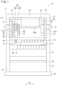
- FIG. 1 is a front view of the press machine 10 according to the present embodiment as viewed from the front.
- the press machine 10 is a so-called transfer press machine, and holds a plurality of punches 12 laterally aligned at a lower end portion of a ram 20 and holds a plurality of dies (not illustrated) corresponding thereto laterally aligned on a support beam 32.
- a plurality of working stages S for processing the workpiece by the punches 12 and the dies is provided.
- a cylindrical workpiece is formed after a blank is punched out from a sheet metal.
- the working stage S at the left side end portion is provided with a workpiece production mechanism 45 to be described in detail later.
- the cylindrical workpiece is sequentially conveyed to the working stage S on the downstream side by a transfer device 14, and is subjected to drawing or ironing to form a pressed product having a predetermined shape.
- a lateral direction of the press machine 10 in FIG. 1 is referred to as a "workpiece conveyance direction H1"
- the left side (left side in FIG. 1 ) when the press machine 10 is viewed from the front is referred to as an "upstream side in the workpiece conveyance direction H1”
- the opposite side thereof is referred to as a "downstream side in the workpiece conveyance direction H1”.
- the ram 20 is supported by a support frame 11 so as to be movable up and down.
- the support frame 11 has a pair of side support walls 31 standing upright from a pedestal portion 30 and facing each other in the lateral direction.
- the support beam 32 is bridged between the pair of side support walls 31 near the lower end portion, and a ceiling wall 33 is bridged over an upper end portion.
- a ram support wall 34 is provided above substantially the center of the pair of side support walls 31 in a vertical direction.
- the ram support wall 34 is bridged between the pair of side support walls 31 at a position close to a rear end portion in a front-rear direction (on a back side in a depth direction in FIG. 1 ), and the upper end portion thereof is connected to the ceiling wall 33.
- a plurality of rails (not illustrated) extending in the vertical direction is attached to a front surface of the ram support wall 34. Moreover, a slider fixed to a rear surface of the ram 20 is engaged with the rails, and the ram 20 is supported slidably in the vertical direction.
- a pair of rotation support portions 31A is provided at a position near the upper end portion of the pair of side support walls 31. Moreover, the both end portions of a shaft 41 extending in the workpiece conveyance direction H1 are rotatably supported by being fitted to bearings or metal bearings provided in the pair of rotation support portions 31A.
- Three or more ram driving cams 42 are integrally rotatably fixed to the shaft 41.
- the ram driving cams 42 have a common cam curve.
- each ram driving cam 42 has a circular shape, and the center of the shaft 41 is located at a position shifted from the center of the circular shape.
- first to third ram driving cams 42 in order from the upstream side in the workpiece conveyance direction H1.
- the entirety of the shaft 41 and the plurality of ram driving cams 42 will be referred to as a "cam shaft 40".
- the first ram driving cam 42 and the third ram driving cam 42 are disposed close to the pair of rotation support portions 31A of the shaft 41.
- the second ram driving cam 42 is disposed close to the first ram driving cam 42.
- the first and second ram driving cams 42 disposed on the upstream side in the workpiece conveyance direction H1 are thinner than the third ram driving cam 42 on the downstream side.
- the thickness of the first and second ram driving cams 42 is about 2/3 of the thickness of the third ram driving cam 42, but the present invention is not limited thereto.
- both the first and second ram driving cams 42 are thinner than the third ram driving cam 42, for example, only one of the first and second ram driving cams 42 may be thinner than the third ram driving cam 42 (see FIG. 5A ), or the three ram driving cams 42 may have the same thickness (see FIG. 5B ), or may have different thicknesses.
- a plurality of abutting portions 21 abutting on the plurality of ram driving cams 42 are rotatably supported in the ram 20. Specifically, a pair of abutting portions 21 is provided at positions of the ram 20 corresponding to the first and third ram driving cams 42 so as to sandwich the first and third ram driving cams 42 in the vertical direction. On the other hand, the abutting portion 21 is provided only on the lower side of the second ram driving cam 42 at a position corresponding to the second ram driving cam 42.
- first and third ram driving cams 42 at both ends are lifting and lowering cams that perform both push up and push down of the ram 20, while the second ram driving cam 42 disposed between the lifting and lowering cams is a lowering cam that only pushes down the ram 20.
- the abutting portions 21 are, for example, rollers, and are disposed between a pair of support projecting walls (not illustrated) projecting forward from the ram 20 and facing each other in the lateral direction. Moreover, a support shaft that is passed between the pair of support projecting walls penetrates the bearings provided at a center portion of the abutting portions 21. Instead of the bearings, metal bearings may be provided at the center portion of the ram 20.
- the abutting portions 21 are not limited to the rollers, and for example, may have a structure in which protruding walls protruding from the ram 20 and facing the ram driving cam 42 from above or below are provided, an arc-shaped groove is provided in the protruding wall, and an inner surface of the groove is covered with a sliding metal, and the ram driving cam 42 abuts on the sliding metal.
- a space between the second ram driving cam 42 and the third ram driving cam 42 of the shaft 41 is wider than a space between the first ram driving cam 42 and the second ram driving cam 42.
- a shaft support portion 35 is provided between the second ram driving cam 42 and the third ram driving cam 42.
- the shaft support portion 35 hangs down from the ceiling wall 33 and has a support groove 35M on the lower surface thereof.
- the support groove 35M has a shape recessed upward, and a recessed inner surface thereof is covered with the sliding metal.
- an outer peripheral surface of the intermediate portion of the shaft 41 abuts on the inner surface of the support groove 35M to suppress upward bending deformation of the intermediate portion of the shaft 41.
- the support groove 35M of the present embodiment is a groove having a semicircular cross section, but may be, for example, a V-shaped groove.
- the workpiece production mechanism 45 is disposed between the first ram driving cam 42 and the second ram driving cam 42 of the shaft 41.
- the workpiece production mechanism 45 includes a cylindrical first punch 46 that punches a blank from a sheet metal, and a second punch 47 that is provided inside the first punch 46 and forms the blank into a cylindrical workpiece.
- the first punch 46 moves up and down integrally with the ram 20, whereas the second punch 47 moves up and down by a lifting and lowering operation different from that of the ram 20.
- An auxiliary cam 49 for lifting and lowering the second punch 47 by a lifting and lowering operation different from that of the ram 20 is provided between the first ram driving cam 42 and the second ram driving cam 42.
- the auxiliary cam 49 is integrally rotatably supported by the shaft 41, and has a cam curve different from the cam curve of the ram driving cam 42.
- the auxiliary cam 49 includes a lowering cam 49A for lowering the second punch 47 and a lifting cam 49B for lifting the second punch 47, but the second punch 42 may be lifted and lowered by one cam.
- thicknesses of the lowering cam 49A and the lifting cam 49B are different (specifically, the lowering cam 49A is thicker than the lifting cam 49B), but may be the same.
- a rail (not illustrated) extending in the vertical direction is attached below the auxiliary cam 49 in the ram 20.
- a slider 50 is slidably supported by the rail.
- the second punch 47 is fixed to the lower end portion of the slider 50, and a support frame 51 is connected to the upper end portion thereof.
- the support frame 51 has a size capable of accommodating the lowering cam 49A and the lifting cam 49B inside, rotatably supports an abutting portion (not illustrated) abutting on the lowering cam 49A at the lower end portion, and rotatably supports an abutting portion (not illustrated) abutting on the lifting cam 49B at the upper end portion. Accordingly, the lowering cam 49A slides the slider 50 downward via the lower abutting portion to lower the second punch 47, and the lifting cam 49B slides the slider 50 upward via the upper abutting portion to lift the second punch 47.
- the configuration of the press machine 10 of the present embodiment has been described as above. Next, effects of the press machine 10 will be described.
- the press machine 10 is started, the cam shaft 40 is rotationally driven, the ram 20 moves up and down, and then press working of a workpiece is performed.
- the ram 20 since the processing reaction force applied to the ram 20 during the press working varies depending on locations of the ram 20, the ram 20 may tilt.
- three or more ram driving cams 42 are provided, and the ram 20 is pushed down by the three or more ram driving cams 42. Therefore, even when magnitude of the processing reaction force received by the ram 20 differs depending on the locations of the ram 20, an inclination of the ram 20 can be suppressed, and the processing accuracy can be improved as compared with the conventional art.
- the press machine 10 of the present embodiment since the intermediate portion of the shaft 41 is rotatably supported by the support groove 35M opened downward, the inclination of the ram 20 is suppressed while the assembly is easy, and the processing accuracy is improved. Specifically, the press machine 10 receives a larger load on the shaft 41 when the ram 20 is lowered to perform press working than when the ram 20 is lifted. In other words, an upward load applied to the shaft 41 is larger than a downward load.
- the rotation support portions 31A fitted to each of the both end portions and the intermediate portion of the shaft 41 are provided, it is difficult to assemble the shaft 41 to the plurality of rotation support portions 31A.
- the shaft 41 is rotatably supported at the both end portions by the pair of rotation support portions 31A and the intermediate portion is rotatably supported by the support groove 35M opened downward, the bending of the shaft 41 due to the upward load is suppressed while the assembly is easy. In other words, the bending of the shaft 41 during press working is suppressed, the inclination of the ram 20 is also suppressed, and the processing accuracy is improved.
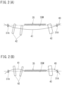
- FIGS. 2A and 2B the bending of the shaft 41 obtained by the simulation is shown in an emphasized way. Specifically, FIG. 2A illustrates a state in which the shaft 41 is bent downward by receiving an own weight of the ram 20 as a load from above, and FIG. 2B illustrates a state in which the shaft 41 is bent upward by receiving a processing reaction force from below.
- the ram driving cams 42 at both ends of the shaft 41 are lifting and lowering cams provided with the abutting portions 21 above and below thereof, and the middle ram driving cam 42 is a lowering cam provided with the abutting portion 21 only therebelow, and further, there is a clearance between the lifting and lowering cams and the upper and lower abutting portions 21.
- the both end portions of the shaft 41 are supported by the rotation support portion 31A, and the intermediate portion thereof is supported by the support groove 35M. Accordingly, the shaft 41 receives a load from above only via the ram driving cams 42 at both ends and bends downward as illustrated in FIG. 2A .
- the shaft 41 can receive a load from below via all the ram driving cams 42 in a state where an upward movement is restricted with respect to the load from below. Accordingly, as well as the assembly of the shaft 41 is easy as described above, the bending of the shaft 41 during press working is suppressed, the inclination of the ram 20 is also suppressed, and the processing accuracy is improved.
- the lowering cam which is the second ram driving cam 42 is disposed away from both ends of the shaft and can be displaced up and down together with the shaft 41, but since the abutting portion 21 is not provided on the upper side, a situation in which collision with the abutting portion 21 on the upper side is repeated can be prevented. Further, while it is necessary to provide the ram 20 with a pair of the abutting portions 21 that abut on the lifting and lowering cam from above and below, and it is only necessary to provide the ram 20 with one abutting portion 21 that abuts on the lowering cam from below, and therefore, manufacturing costs including time and efforts for assembly can be suppressed.
- the second ram driving cam 42 and the upper abutting portion 21 may point contact due to the bending of the shaft 41, and the bearing of the abutting portion 21 may be damaged.
- the intermediate portion of the shaft 41 supported by the support groove 35M can be displaced up and down together with the shaft 41 and collide with the support groove 35M.
- an area of the intermediate portion and the support groove 35M is larger than that of the second ram driving cam 42 and the abutting portions 21, and the intermediate portion surface and the support groove 35M contact with each other, the intermediate portion is less likely to be damaged.
- the processing reaction force is larger in the working performed on the working stage S on the upstream side in the workpiece conveyance direction H1 than in the working performed on the working stage S on the downstream side.
- the processing reaction force tends to be larger on the upstream side of the ram 20 in the workpiece conveyance direction H1.
- the support groove 35M can be arranged in the intermediate portion of the shaft 41, and thus the bending of the shaft due to the upward load can be effectively suppressed.
- the first and second ram driving cams 42 are thinner than the third ram driving cam 42, it is possible to suppress the shaft 41 from becoming large in the axial direction.
- the press machine 10 not according to the present invention is illustrated in FIG. 3 , and is different from the press machine 10 of the first embodiment in not including the workpiece production mechanism 45. Also in the press machine 10 of the present embodiment, since the ram 20 receives different processing reaction forces depending on the locations, three or more ram driving cams 42 are provided, and by pushing down the ram 20 with the three or more ram driving cams 42, similarly to the press machine 10 of the first embodiment, it is possible to suppress the inclination of the ram 20 and improve the processing accuracy as compared with the conventional art.
- the press machine 10 of the present embodiment is illustrated in FIG. 4 , and is different from the press machine 10 of the first embodiment in that the punches 12 and the dies are fixed via die sets 23 and 24.
- the shaft 41 is formed by connecting a first shaft 41A and a second shaft 41B by, for example, a spline, whereby one shaft 41 includes a plurality of, three or more (for example, four) ram driving cams 42.
- the present embodiment also achieves the effects similar to those of the first embodiment.
- the so-called transfer press machine including the plurality of working stages S and the transfer device 14 is exemplified as the press machine 10, but a press machine not including the transfer device 14 may be used.
- the configuration of the present invention to the transfer press machine, the inclination of the ram is suppressed as compared with the conventional art. Thus, it is possible to enjoy the effect of improving the processing accuracy.
- the second punch 47 communicates with the auxiliary cam 49 provided integrally rotatably with the shaft 41 via the slider 50, but the present invention is not limited thereto, and the following configuration may be adopted.
- an auxiliary shaft 36 (see FIG. 1 ) extending in parallel with the shaft 41 below the support beam 32 and rotating in conjunction with the shaft 41 may be provided
- an auxiliary cam may be provided in the auxiliary shaft 36
- a lever may be tiltably supported by the support frame 11 of the press machine 10 and tilted by the auxiliary cam, so that the second punch may be connected to a tip end of a tilting lever thereof.
- an auxiliary shaft 37 that extends vertically outside the support frame 11 of the press machine 10 supporting the ram 20 so as to be movable up and down and that is connected to the shaft 41 may be provided (see FIG. 4 ).
- One end of the tilting lever tiltably supported by the support frame 11 may be engaged with an auxiliary cam provided in the auxiliary shaft 37, and the other end may be connected to the second punch.
- the ram driving cams 42 at both ends are lifting and lowering cams
- the ram driving cams 42 disposed between the lifting and lowering cams are lowering cams.
- one of the ram driving cams 42 at both ends may be a lowering cam
- the other ram driving cams 42 may be lifting and lowering cams.
- the plurality of ram driving cams 42 is disposed in a larger number on the upstream side than on the downstream side in the workpiece conveyance direction H1, but for example, the plurality of ram driving cams may be disposed in a larger number on the downstream side in the workpiece conveyance direction H1.
- the ram driving cams 42 may be arranged at equal intervals with respect to the workpiece conveyance direction H1.
- the shaft support portion 35 is disposed in a section in which a gap between the ram driving cams 42 is wide among the plurality of ram driving cams 42 (specifically, between the second ram driving cam 42 and the third ram driving cam 42), but the shaft support portion 35 may be disposed in a section in which the gap between the ram driving cams 42 is narrow (for example, between the first ram driving cam 42 and the second ram driving cam 42).
- the number of the shaft support portions 35 is not limited to one, and a plurality of the shaft support portions may be provided as illustrated in FIGS. 4 and 5B .
- the clearance is provided between the ram driving cam 42 and the abutting portions 21, but the clearance may not be provided.
Landscapes
- Engineering & Computer Science (AREA)
- Mechanical Engineering (AREA)
- Press Drives And Press Lines (AREA)
- Shaping Metal By Deep-Drawing, Or The Like (AREA)
Description
- The present invention relates to a press machine.
- Conventionally, as such type of press machine, a press machine that lifts and lowers a ram with a cam is known (see, for example,
JP 2021-120161 A -
JP 2878956 B2 US 3,785,194 A andJP H11-90547 A - It is required to improve processing accuracy of press working with respect to the conventional press machine described above.
- A press machine according to one aspect of the present invention made in order to solve the above problem includes the features specified in
claim 1. -
-
FIG. 1 is a front view of a press machine according to a first embodiment; -
FIG. 2A is a conceptual diagram illustrating a state in which a cam shaft is bent by its own weight, andFIG. 2B is a conceptual diagram illustrating a state in which the cam shaft is bent by a processing reaction force; -
FIG. 3 is a front view of a press machine according to a second embodiment; -
FIG. 4 is a front view of a press machine according to a third embodiment; and -
FIG. 5 is a front view of a press machine according to a modification. - A
press machine 10 according to one embodiment of the present invention will be described with reference toFIGS. 1 and2 .FIG. 1 is a front view of thepress machine 10 according to the present embodiment as viewed from the front. Thepress machine 10 is a so-called transfer press machine, and holds a plurality ofpunches 12 laterally aligned at a lower end portion of aram 20 and holds a plurality of dies (not illustrated) corresponding thereto laterally aligned on asupport beam 32. Moreover, a plurality of working stages S for processing the workpiece by thepunches 12 and the dies is provided. Further, in a working stage S at a left side end portion of the plurality of working stages S, a cylindrical workpiece is formed after a blank is punched out from a sheet metal. In order to perform a two-stage motion as described above, the working stage S at the left side end portion is provided with aworkpiece production mechanism 45 to be described in detail later. Moreover, the cylindrical workpiece is sequentially conveyed to the working stage S on the downstream side by atransfer device 14, and is subjected to drawing or ironing to form a pressed product having a predetermined shape. - A drive mechanism of the
ram 20 will now be described. Hereinafter, a lateral direction of thepress machine 10 inFIG. 1 is referred to as a "workpiece conveyance direction H1", the left side (left side inFIG. 1 ) when thepress machine 10 is viewed from the front is referred to as an "upstream side in the workpiece conveyance direction H1", and the opposite side thereof is referred to as a "downstream side in the workpiece conveyance direction H1". - The
ram 20 is supported by asupport frame 11 so as to be movable up and down. Thesupport frame 11 has a pair ofside support walls 31 standing upright from apedestal portion 30 and facing each other in the lateral direction. Thesupport beam 32 is bridged between the pair ofside support walls 31 near the lower end portion, and aceiling wall 33 is bridged over an upper end portion. Further, aram support wall 34 is provided above substantially the center of the pair ofside support walls 31 in a vertical direction. Theram support wall 34 is bridged between the pair ofside support walls 31 at a position close to a rear end portion in a front-rear direction (on a back side in a depth direction inFIG. 1 ), and the upper end portion thereof is connected to theceiling wall 33. Further, a plurality of rails (not illustrated) extending in the vertical direction is attached to a front surface of theram support wall 34. Moreover, a slider fixed to a rear surface of theram 20 is engaged with the rails, and theram 20 is supported slidably in the vertical direction. - A pair of
rotation support portions 31A is provided at a position near the upper end portion of the pair ofside support walls 31. Moreover, the both end portions of ashaft 41 extending in the workpiece conveyance direction H1 are rotatably supported by being fitted to bearings or metal bearings provided in the pair ofrotation support portions 31A. - Three or more
ram driving cams 42 are integrally rotatably fixed to theshaft 41. Theram driving cams 42 have a common cam curve. Specifically, eachram driving cam 42 has a circular shape, and the center of theshaft 41 is located at a position shifted from the center of the circular shape. In the present embodiment, a case where threeram driving cams 42 are provided will be described as an example. Hereinafter, in order to distinguish the threeram driving cams 42, they are referred to as "first to thirdram driving cams 42" in order from the upstream side in the workpiece conveyance direction H1. Further, the entirety of theshaft 41 and the plurality ofram driving cams 42 will be referred to as a "cam shaft 40". - The first
ram driving cam 42 and the thirdram driving cam 42 are disposed close to the pair ofrotation support portions 31A of theshaft 41. On the other hand, the secondram driving cam 42 is disposed close to the firstram driving cam 42. - The first and second
ram driving cams 42 disposed on the upstream side in the workpiece conveyance direction H1 are thinner than the thirdram driving cam 42 on the downstream side. In the present embodiment, the thickness of the first and secondram driving cams 42 is about 2/3 of the thickness of the thirdram driving cam 42, but the present invention is not limited thereto. Further, although both the first and secondram driving cams 42 are thinner than the thirdram driving cam 42, for example, only one of the first and secondram driving cams 42 may be thinner than the third ram driving cam 42 (seeFIG. 5A ), or the threeram driving cams 42 may have the same thickness (seeFIG. 5B ), or may have different thicknesses. In addition, in the present invention, the left side inFIG. 1 with respect to the center of theram 20 in the workpiece conveyance direction H1 (the lateral direction) as a boundary is referred to as an "upstream side in the workpiece conveyance direction H1", and the right side from the center is referred to as a "downstream side in the workpiece conveyance direction H1". - A plurality of abutting
portions 21 abutting on the plurality ofram driving cams 42 are rotatably supported in theram 20. Specifically, a pair ofabutting portions 21 is provided at positions of theram 20 corresponding to the first and thirdram driving cams 42 so as to sandwich the first and thirdram driving cams 42 in the vertical direction. On the other hand, theabutting portion 21 is provided only on the lower side of the secondram driving cam 42 at a position corresponding to the secondram driving cam 42. In other words, the first and thirdram driving cams 42 at both ends are lifting and lowering cams that perform both push up and push down of theram 20, while the secondram driving cam 42 disposed between the lifting and lowering cams is a lowering cam that only pushes down theram 20. - The abutting
portions 21 are, for example, rollers, and are disposed between a pair of support projecting walls (not illustrated) projecting forward from theram 20 and facing each other in the lateral direction. Moreover, a support shaft that is passed between the pair of support projecting walls penetrates the bearings provided at a center portion of theabutting portions 21. Instead of the bearings, metal bearings may be provided at the center portion of theram 20. Further, theabutting portions 21 are not limited to the rollers, and for example, may have a structure in which protruding walls protruding from theram 20 and facing theram driving cam 42 from above or below are provided, an arc-shaped groove is provided in the protruding wall, and an inner surface of the groove is covered with a sliding metal, and theram driving cam 42 abuts on the sliding metal. - As described above, a space between the second
ram driving cam 42 and the thirdram driving cam 42 of theshaft 41 is wider than a space between the firstram driving cam 42 and the secondram driving cam 42. Ashaft support portion 35 is provided between the secondram driving cam 42 and the thirdram driving cam 42. Theshaft support portion 35 hangs down from theceiling wall 33 and has asupport groove 35M on the lower surface thereof. Thesupport groove 35M has a shape recessed upward, and a recessed inner surface thereof is covered with the sliding metal. Moreover, an outer peripheral surface of the intermediate portion of theshaft 41 abuts on the inner surface of thesupport groove 35M to suppress upward bending deformation of the intermediate portion of theshaft 41. Thesupport groove 35M of the present embodiment is a groove having a semicircular cross section, but may be, for example, a V-shaped groove. - On the other hand, the
workpiece production mechanism 45 is disposed between the firstram driving cam 42 and the secondram driving cam 42 of theshaft 41. Specifically, theworkpiece production mechanism 45 includes a cylindricalfirst punch 46 that punches a blank from a sheet metal, and asecond punch 47 that is provided inside thefirst punch 46 and forms the blank into a cylindrical workpiece. Thefirst punch 46 moves up and down integrally with theram 20, whereas thesecond punch 47 moves up and down by a lifting and lowering operation different from that of theram 20. Anauxiliary cam 49 for lifting and lowering thesecond punch 47 by a lifting and lowering operation different from that of theram 20 is provided between the firstram driving cam 42 and the secondram driving cam 42. - The
auxiliary cam 49 is integrally rotatably supported by theshaft 41, and has a cam curve different from the cam curve of theram driving cam 42. In the present embodiment, theauxiliary cam 49 includes a loweringcam 49A for lowering thesecond punch 47 and alifting cam 49B for lifting thesecond punch 47, but thesecond punch 42 may be lifted and lowered by one cam. Further, in the present embodiment, thicknesses of the loweringcam 49A and thelifting cam 49B are different (specifically, the loweringcam 49A is thicker than the liftingcam 49B), but may be the same. - A rail (not illustrated) extending in the vertical direction is attached below the
auxiliary cam 49 in theram 20. Aslider 50 is slidably supported by the rail. Thesecond punch 47 is fixed to the lower end portion of theslider 50, and asupport frame 51 is connected to the upper end portion thereof. Thesupport frame 51 has a size capable of accommodating the loweringcam 49A and thelifting cam 49B inside, rotatably supports an abutting portion (not illustrated) abutting on the loweringcam 49A at the lower end portion, and rotatably supports an abutting portion (not illustrated) abutting on thelifting cam 49B at the upper end portion. Accordingly, the loweringcam 49A slides theslider 50 downward via the lower abutting portion to lower thesecond punch 47, and thelifting cam 49B slides theslider 50 upward via the upper abutting portion to lift thesecond punch 47. - The configuration of the
press machine 10 of the present embodiment has been described as above. Next, effects of thepress machine 10 will be described. When thepress machine 10 is started, thecam shaft 40 is rotationally driven, theram 20 moves up and down, and then press working of a workpiece is performed. Here, since the processing reaction force applied to theram 20 during the press working varies depending on locations of theram 20, theram 20 may tilt. However, in thepress machine 10 of the present embodiment, three or moreram driving cams 42 are provided, and theram 20 is pushed down by the three or moreram driving cams 42. Therefore, even when magnitude of the processing reaction force received by theram 20 differs depending on the locations of theram 20, an inclination of theram 20 can be suppressed, and the processing accuracy can be improved as compared with the conventional art. - Moreover, in the
press machine 10 of the present embodiment, since the intermediate portion of theshaft 41 is rotatably supported by thesupport groove 35M opened downward, the inclination of theram 20 is suppressed while the assembly is easy, and the processing accuracy is improved. Specifically, thepress machine 10 receives a larger load on theshaft 41 when theram 20 is lowered to perform press working than when theram 20 is lifted. In other words, an upward load applied to theshaft 41 is larger than a downward load. However, if therotation support portions 31A fitted to each of the both end portions and the intermediate portion of theshaft 41 are provided, it is difficult to assemble theshaft 41 to the plurality ofrotation support portions 31A. On the other hand, in thepress machine 10, since theshaft 41 is rotatably supported at the both end portions by the pair ofrotation support portions 31A and the intermediate portion is rotatably supported by thesupport groove 35M opened downward, the bending of theshaft 41 due to the upward load is suppressed while the assembly is easy. In other words, the bending of theshaft 41 during press working is suppressed, the inclination of theram 20 is also suppressed, and the processing accuracy is improved. - Here, in
FIGS. 2A and 2B , the bending of theshaft 41 obtained by the simulation is shown in an emphasized way. Specifically,FIG. 2A illustrates a state in which theshaft 41 is bent downward by receiving an own weight of theram 20 as a load from above, andFIG. 2B illustrates a state in which theshaft 41 is bent upward by receiving a processing reaction force from below. As described above, in thepress machine 10 of the present embodiment, theram driving cams 42 at both ends of theshaft 41 are lifting and lowering cams provided with the abuttingportions 21 above and below thereof, and the middleram driving cam 42 is a lowering cam provided with the abuttingportion 21 only therebelow, and further, there is a clearance between the lifting and lowering cams and the upper and lower abuttingportions 21. Further, the both end portions of theshaft 41 are supported by therotation support portion 31A, and the intermediate portion thereof is supported by thesupport groove 35M. Accordingly, theshaft 41 receives a load from above only via theram driving cams 42 at both ends and bends downward as illustrated inFIG. 2A . On the other hand, as illustrated inFIG. 2B , theshaft 41 can receive a load from below via all theram driving cams 42 in a state where an upward movement is restricted with respect to the load from below. Accordingly, as well as the assembly of theshaft 41 is easy as described above, the bending of theshaft 41 during press working is suppressed, the inclination of theram 20 is also suppressed, and the processing accuracy is improved. - As illustrated in
FIGS. 2A and 2B , since both end portions of theshaft 41 are supported by therotation support portions 31A, a displacement amount in the vertical direction at the positions near both ends is smaller than that at the intermediate portion. Moreover, since the first and thirdram driving cams 42 at both ends of the plurality ofram driving cams 42 are used as lifting and lowering cams, abutting on the upper and lower abuttingportions 21 can be stabilized. On the other hand, the lowering cam which is the secondram driving cam 42 is disposed away from both ends of the shaft and can be displaced up and down together with theshaft 41, but since the abuttingportion 21 is not provided on the upper side, a situation in which collision with the abuttingportion 21 on the upper side is repeated can be prevented. Further, while it is necessary to provide theram 20 with a pair of the abuttingportions 21 that abut on the lifting and lowering cam from above and below, and it is only necessary to provide theram 20 with one abuttingportion 21 that abuts on the lowering cam from below, and therefore, manufacturing costs including time and efforts for assembly can be suppressed. In addition, the secondram driving cam 42 and the upper abuttingportion 21 if provided, may point contact due to the bending of theshaft 41, and the bearing of the abuttingportion 21 may be damaged. However, as described above, since the upper abuttingportion 21 is not provided, such situation can be prevented. Further, the intermediate portion of theshaft 41 supported by thesupport groove 35M can be displaced up and down together with theshaft 41 and collide with thesupport groove 35M. However, since an area of the intermediate portion and thesupport groove 35M is larger than that of the secondram driving cam 42 and the abuttingportions 21, and the intermediate portion surface and thesupport groove 35M contact with each other, the intermediate portion is less likely to be damaged. - Further, in the
press machine 10 including the plurality of working stages S, the processing reaction force is larger in the working performed on the working stage S on the upstream side in the workpiece conveyance direction H1 than in the working performed on the working stage S on the downstream side. In particular, as in thepress machine 10 of the present embodiment, in thepress machine 10 having theworkpiece production mechanism 45 that punches the blank from the sheet metal at an upstream side end portion of the working stage S and then forms the cylindrical workpiece, the processing reaction force tends to be larger on the upstream side of theram 20 in the workpiece conveyance direction H1. To cope with this, in thepress machine 10 of the present embodiment, since moreram driving cams 42 are disposed on the upstream side in the workpiece conveyance direction H1 than on the downstream side, the inclination of theram 20 is suppressed, and the processing accuracy can be improved. - Furthermore, in the present embodiment, by disposing the second
ram driving cam 42 close to the upstream side in the workpiece conveyance direction H1, thesupport groove 35M can be arranged in the intermediate portion of theshaft 41, and thus the bending of the shaft due to the upward load can be effectively suppressed. Further, in the present embodiment, since the first and secondram driving cams 42 are thinner than the thirdram driving cam 42, it is possible to suppress theshaft 41 from becoming large in the axial direction. - The
press machine 10 not according to the present invention is illustrated inFIG. 3 , and is different from thepress machine 10 of the first embodiment in not including theworkpiece production mechanism 45. Also in thepress machine 10 of the present embodiment, since theram 20 receives different processing reaction forces depending on the locations, three or moreram driving cams 42 are provided, and by pushing down theram 20 with the three or moreram driving cams 42, similarly to thepress machine 10 of the first embodiment, it is possible to suppress the inclination of theram 20 and improve the processing accuracy as compared with the conventional art. - The
press machine 10 of the present embodiment is illustrated inFIG. 4 , and is different from thepress machine 10 of the first embodiment in that thepunches 12 and the dies are fixed via die sets 23 and 24. Further, in thepress machine 10 of the present embodiment, theshaft 41 is formed by connecting afirst shaft 41A and asecond shaft 41B by, for example, a spline, whereby oneshaft 41 includes a plurality of, three or more (for example, four)ram driving cams 42. The present embodiment also achieves the effects similar to those of the first embodiment. - In the above embodiment, the so-called transfer press machine including the plurality of working stages S and the
transfer device 14 is exemplified as thepress machine 10, but a press machine not including thetransfer device 14 may be used. In addition, as in the above embodiment, by applying the configuration of the present invention to the transfer press machine, the inclination of the ram is suppressed as compared with the conventional art. Thus, it is possible to enjoy the effect of improving the processing accuracy. - In the
workpiece production mechanism 45 of the above embodiment, thesecond punch 47 communicates with theauxiliary cam 49 provided integrally rotatably with theshaft 41 via theslider 50, but the present invention is not limited thereto, and the following configuration may be adopted. In other words, an auxiliary shaft 36 (seeFIG. 1 ) extending in parallel with theshaft 41 below thesupport beam 32 and rotating in conjunction with theshaft 41 may be provided, an auxiliary cam may be provided in theauxiliary shaft 36, and a lever may be tiltably supported by thesupport frame 11 of thepress machine 10 and tilted by the auxiliary cam, so that the second punch may be connected to a tip end of a tilting lever thereof. Further, anauxiliary shaft 37 that extends vertically outside thesupport frame 11 of thepress machine 10 supporting theram 20 so as to be movable up and down and that is connected to theshaft 41 may be provided (seeFIG. 4 ). One end of the tilting lever tiltably supported by thesupport frame 11 may be engaged with an auxiliary cam provided in theauxiliary shaft 37, and the other end may be connected to the second punch. - Further, in the above embodiment, the
ram driving cams 42 at both ends are lifting and lowering cams, and theram driving cams 42 disposed between the lifting and lowering cams are lowering cams. However, for example, as illustrated inFIG. 5A , one of theram driving cams 42 at both ends may be a lowering cam, and the otherram driving cams 42 may be lifting and lowering cams. - In the above embodiment, the plurality of
ram driving cams 42 is disposed in a larger number on the upstream side than on the downstream side in the workpiece conveyance direction H1, but for example, the plurality of ram driving cams may be disposed in a larger number on the downstream side in the workpiece conveyance direction H1. Alternatively, as illustrated inFIG. 5B , theram driving cams 42 may be arranged at equal intervals with respect to the workpiece conveyance direction H1. - In the above embodiment, the
shaft support portion 35 is disposed in a section in which a gap between theram driving cams 42 is wide among the plurality of ram driving cams 42 (specifically, between the secondram driving cam 42 and the third ram driving cam 42), but theshaft support portion 35 may be disposed in a section in which the gap between theram driving cams 42 is narrow (for example, between the firstram driving cam 42 and the second ram driving cam 42). Further, the number of theshaft support portions 35 is not limited to one, and a plurality of the shaft support portions may be provided as illustrated inFIGS. 4 and5B . - In the above embodiment, the clearance is provided between the
ram driving cam 42 and the abuttingportions 21, but the clearance may not be provided. - In addition, although specific examples of the technology included in the claims are disclosed in the present specification and the drawings, the technology described in the claims is not limited to these specific examples.
Claims (5)
- A press machine (10) comprising:a ram (20);a shaft (41);three or more ram driving cams (42), for the one ram (20), configured to push down the ram (20) toward a bottom dead center, the plurality of ram driving cams (42) being integrally rotatable with the common shaft (41);a plurality of working stages (S) arranged in an axial direction of the shaft (41) below the ram and on which press working of a plurality of workpieces is simultaneously performed by lowering of the ram (20); anda transfer device (14) configured to convey each of the plurality of workpieces on the plurality of working stages (S) to adjacent one of the plurality of working stages (S) each time the ram (20) moves up and down, whereinboth end portions of the shaft (41) are rotatably supported by a pair of rotation support portions (31A) fitted to the both end portions between which all of the plurality of ram driving cams (42) are disposed, and an intermediate portion of the shaft (41) disposed between the ram driving cams (42) is rotatably supported by a support groove (35M) opened downward,the plurality of ram driving cams (42) includes at least two lifting and lowering cams configured to apply both a pushing down force and a pushing up force to the ram (20), and at least one lowering cam configured to apply only the pushing down force to the ram (20),in the working stage (S) at an upstream end portion, a workpiece production mechanism (45) configured to punch a blank from a sheet metal and to form the blank into a cylindrical workpiece is provided,in the plurality of working stages (S) on a downstream side of the workpiece production mechanism (45) in a workpiece conveyance direction (H1), the cylindrical workpiece is formed by drawing or ironing,the two ram driving cams (42) on the upstream side in the workpiece conveyance direction (H1) are disposed on both sides of the workpiece production mechanism (45), and the workpiece production mechanism (45) includesa first punch (46) having a cylindrical shape, fixed to the ram (20), and configured to punch the blank from the sheet metal;a second punch (47) fitted inside the first punch (46) and configured to form the blank into a cylindrical workpiece; andan auxiliary cam (49) provided integrally rotatable with the shaft (41) and configured to lift and lower the second punch (47) at a timing different from a lifting and lowering operation of the ram (20).
- The press machine (10) according to claim 1, wherein the ram driving cams (42) at both ends of the plurality of ram driving cams (42) are the lifting and lowering cams.
- The press machine (10) according to claim 1 or 2, wherein the plurality of ram driving cams (42) is disposed in a larger number on the upstream side than on the downstream side with respect to a center of the ram (20) in the workpiece conveyance direction.
- The press machine (10) according to any one of claims 1 to 3, wherein a total number of the plurality of ram driving cams (42) is three, and the intermediate portion sandwiched between the two ram driving cams (42) on the downstream side of the shaft (41) is supported by the support groove (35M).
- The press machine (10) according to any one of claims 1 to 4, wherein one or both of the two ram driving cams (42) on the upstream side are thinner than the ram driving cam (42) other than the two ram driving cams (42) on the upstream side.
Applications Claiming Priority (1)
| Application Number | Priority Date | Filing Date | Title |
|---|---|---|---|
| JP2022054907A JP7210124B1 (en) | 2022-03-30 | 2022-03-30 | press machine |
Publications (2)
| Publication Number | Publication Date |
|---|---|
| EP4252932A1 EP4252932A1 (en) | 2023-10-04 |
| EP4252932B1 true EP4252932B1 (en) | 2025-06-04 |
Family
ID=84978276
Family Applications (1)
| Application Number | Title | Priority Date | Filing Date |
|---|---|---|---|
| EP23162965.0A Active EP4252932B1 (en) | 2022-03-30 | 2023-03-20 | Press machine |
Country Status (5)
| Country | Link |
|---|---|
| US (1) | US12441073B2 (en) |
| EP (1) | EP4252932B1 (en) |
| JP (1) | JP7210124B1 (en) |
| KR (1) | KR102872163B1 (en) |
| CN (1) | CN116890061B (en) |
Families Citing this family (1)
| Publication number | Priority date | Publication date | Assignee | Title |
|---|---|---|---|---|
| BE1030004B1 (en) * | 2021-12-10 | 2023-07-10 | Soenen Tech Nv | FOUR SLIDE PERFORATION PRESS AND HOW TO CONTROL A FOUR SLIDE PERFORATION PRESS |
Family Cites Families (14)
| Publication number | Priority date | Publication date | Assignee | Title |
|---|---|---|---|---|
| US3785194A (en) * | 1972-09-29 | 1974-01-15 | Textron Inc | Press |
| IT1224044B (en) * | 1988-12-29 | 1990-09-26 | Prima Ind Spa | PRECISION BENDING PRESS FOR LONG SHEET PIECES |
| JPH04288931A (en) * | 1991-03-18 | 1992-10-14 | Toyo Koki:Kk | Press brake |
| JP2878956B2 (en) * | 1994-01-25 | 1999-04-05 | 旭精機工業株式会社 | Method and apparatus for correcting bottom dead center position of cam press |
| JP3193252B2 (en) * | 1994-11-30 | 2001-07-30 | 旭精機工業株式会社 | Cam type small transfer press machine |
| JP3435321B2 (en) * | 1997-09-18 | 2003-08-11 | 旭精機工業株式会社 | Drawing method of transfer press and transfer press |
| JPH11309598A (en) * | 1998-04-22 | 1999-11-09 | Riso Kagaku Corp | Modular press |
| JP3868765B2 (en) * | 2001-06-27 | 2007-01-17 | 旭精機工業株式会社 | Transfer press machine |
| JP2005224855A (en) * | 2004-02-16 | 2005-08-25 | Asahi-Seiki Mfg Co Ltd | Press machine, system control program, and system control method |
| JP2016198819A (en) * | 2015-04-13 | 2016-12-01 | 株式会社吉野機械製作所 | Press machine |
| TWM557145U (en) * | 2017-09-11 | 2018-03-21 | 炫安企業股份有限公司 | Press device |
| JP6593947B1 (en) | 2019-05-17 | 2019-10-23 | 旭精機工業株式会社 | Press machine and press molding method |
| JP6676815B1 (en) * | 2019-07-31 | 2020-04-08 | 旭精機工業株式会社 | Press equipment |
| JP6840448B1 (en) | 2020-01-31 | 2021-03-10 | 旭精機工業株式会社 | Press machine and manufacturing method of pressed products |
-
2022
- 2022-03-30 JP JP2022054907A patent/JP7210124B1/en active Active
-
2023
- 2023-02-14 KR KR1020230019143A patent/KR102872163B1/en active Active
- 2023-02-20 CN CN202310140941.4A patent/CN116890061B/en active Active
- 2023-03-17 US US18/122,866 patent/US12441073B2/en active Active
- 2023-03-20 EP EP23162965.0A patent/EP4252932B1/en active Active
Also Published As
| Publication number | Publication date |
|---|---|
| CN116890061B (en) | 2026-04-17 |
| US20230311441A1 (en) | 2023-10-05 |
| JP7210124B1 (en) | 2023-01-23 |
| KR102872163B1 (en) | 2025-10-16 |
| JP2023147423A (en) | 2023-10-13 |
| KR20230141455A (en) | 2023-10-10 |
| US12441073B2 (en) | 2025-10-14 |
| CN116890061A (en) | 2023-10-17 |
| EP4252932A1 (en) | 2023-10-04 |
Similar Documents
| Publication | Publication Date | Title |
|---|---|---|
| EP1535674B1 (en) | Negative-angle press-working die | |
| US5746082A (en) | Thin sheet forming die assembly including lower die cylindrical member having varied diameters | |
| US12441073B2 (en) | Press machine | |
| EP2656934A1 (en) | Multi-high rolling mill equipped with work roll shift function | |
| JP4746914B2 (en) | Press method and press mold | |
| KR20000011868A (en) | Machine for punching and bending metal sheets | |
| CN101344193B (en) | Tubular product and manufacturing method and manufacturing device thereof | |
| US3596498A (en) | Press | |
| JP3531441B2 (en) | Composite press mold | |
| JP2004009066A (en) | Press for deep-drawing | |
| JPH01197012A (en) | Holding device to follow work for thrust bending | |
| JPH0839365A (en) | Sleeve press-fitting device | |
| JPH0871682A (en) | Bed knockout device for forging press | |
| JP3141207U (en) | Die for press bending | |
| JP4634094B2 (en) | Hemming method | |
| CN113291835A (en) | Clamping device and automation equipment | |
| JP2007196234A (en) | LOADER FOR PRESS DEVICE AND PRESS DEVICE SYSTEM | |
| JP2010194581A (en) | Press device | |
| JPH11244966A (en) | Method and apparatus for lifting and lowering a free table on a work table in a plate material processing machine | |
| JP2001018023A (en) | Press mold | |
| JP3544467B2 (en) | Panel edge bending mold | |
| CN119343228A (en) | Progressive die and processing method using the progressive die | |
| EP1657006B1 (en) | Drawing die with stabilizer | |
| EP4529497B1 (en) | Apparatus and method for making a z-shaped profile on a sheet metal part | |
| JP5154107B2 (en) | Press work processing equipment |
Legal Events
| Date | Code | Title | Description |
|---|---|---|---|
| PUAI | Public reference made under article 153(3) epc to a published international application that has entered the european phase |
Free format text: ORIGINAL CODE: 0009012 |
|
| STAA | Information on the status of an ep patent application or granted ep patent |
Free format text: STATUS: EXAMINATION IS IN PROGRESS |
|
| 17P | Request for examination filed |
Effective date: 20230320 |
|
| AK | Designated contracting states |
Kind code of ref document: A1 Designated state(s): AL AT BE BG CH CY CZ DE DK EE ES FI FR GB GR HR HU IE IS IT LI LT LU LV MC ME MK MT NL NO PL PT RO RS SE SI SK SM TR |
|
| GRAP | Despatch of communication of intention to grant a patent |
Free format text: ORIGINAL CODE: EPIDOSNIGR1 |
|
| STAA | Information on the status of an ep patent application or granted ep patent |
Free format text: STATUS: GRANT OF PATENT IS INTENDED |
|
| INTG | Intention to grant announced |
Effective date: 20250221 |
|
| RIC1 | Information provided on ipc code assigned before grant |
Ipc: B30B 1/26 20060101ALN20250213BHEP Ipc: B21D 43/05 20060101ALN20250213BHEP Ipc: B21D 22/28 20060101ALN20250213BHEP Ipc: B21D 28/32 20060101ALI20250213BHEP Ipc: B21D 28/02 20060101ALI20250213BHEP Ipc: B30B 15/14 20060101ALI20250213BHEP Ipc: B21D 51/10 20060101ALI20250213BHEP Ipc: B30B 1/14 20060101ALI20250213BHEP Ipc: B30B 1/06 20060101ALI20250213BHEP Ipc: B21D 51/26 20060101ALI20250213BHEP Ipc: B21D 24/00 20060101AFI20250213BHEP |
|
| GRAS | Grant fee paid |
Free format text: ORIGINAL CODE: EPIDOSNIGR3 |
|
| GRAA | (expected) grant |
Free format text: ORIGINAL CODE: 0009210 |
|
| STAA | Information on the status of an ep patent application or granted ep patent |
Free format text: STATUS: THE PATENT HAS BEEN GRANTED |
|
| AK | Designated contracting states |
Kind code of ref document: B1 Designated state(s): AL AT BE BG CH CY CZ DE DK EE ES FI FR GB GR HR HU IE IS IT LI LT LU LV MC ME MK MT NL NO PL PT RO RS SE SI SK SM TR |
|
| REG | Reference to a national code |
Ref country code: GB Ref legal event code: FG4D |
|
| REG | Reference to a national code |
Ref country code: CH Ref legal event code: EP |
|
| REG | Reference to a national code |
Ref country code: DE Ref legal event code: R096 Ref document number: 602023003764 Country of ref document: DE |
|
| REG | Reference to a national code |
Ref country code: IE Ref legal event code: FG4D |
|
| REG | Reference to a national code |
Ref country code: NL Ref legal event code: MP Effective date: 20250604 |
|
| PG25 | Lapsed in a contracting state [announced via postgrant information from national office to epo] |
Ref country code: ES Free format text: LAPSE BECAUSE OF FAILURE TO SUBMIT A TRANSLATION OF THE DESCRIPTION OR TO PAY THE FEE WITHIN THE PRESCRIBED TIME-LIMIT Effective date: 20250604 Ref country code: FI Free format text: LAPSE BECAUSE OF FAILURE TO SUBMIT A TRANSLATION OF THE DESCRIPTION OR TO PAY THE FEE WITHIN THE PRESCRIBED TIME-LIMIT Effective date: 20250604 |
|
| REG | Reference to a national code |
Ref country code: LT Ref legal event code: MG9D |
|
| PG25 | Lapsed in a contracting state [announced via postgrant information from national office to epo] |
Ref country code: GR Free format text: LAPSE BECAUSE OF FAILURE TO SUBMIT A TRANSLATION OF THE DESCRIPTION OR TO PAY THE FEE WITHIN THE PRESCRIBED TIME-LIMIT Effective date: 20250905 Ref country code: NO Free format text: LAPSE BECAUSE OF FAILURE TO SUBMIT A TRANSLATION OF THE DESCRIPTION OR TO PAY THE FEE WITHIN THE PRESCRIBED TIME-LIMIT Effective date: 20250904 |
|
| PG25 | Lapsed in a contracting state [announced via postgrant information from national office to epo] |
Ref country code: PL Free format text: LAPSE BECAUSE OF FAILURE TO SUBMIT A TRANSLATION OF THE DESCRIPTION OR TO PAY THE FEE WITHIN THE PRESCRIBED TIME-LIMIT Effective date: 20250604 |
|
| PG25 | Lapsed in a contracting state [announced via postgrant information from national office to epo] |
Ref country code: BG Free format text: LAPSE BECAUSE OF FAILURE TO SUBMIT A TRANSLATION OF THE DESCRIPTION OR TO PAY THE FEE WITHIN THE PRESCRIBED TIME-LIMIT Effective date: 20250604 |
|
| PG25 | Lapsed in a contracting state [announced via postgrant information from national office to epo] |
Ref country code: HR Free format text: LAPSE BECAUSE OF FAILURE TO SUBMIT A TRANSLATION OF THE DESCRIPTION OR TO PAY THE FEE WITHIN THE PRESCRIBED TIME-LIMIT Effective date: 20250604 |
|
| PG25 | Lapsed in a contracting state [announced via postgrant information from national office to epo] |
Ref country code: RS Free format text: LAPSE BECAUSE OF FAILURE TO SUBMIT A TRANSLATION OF THE DESCRIPTION OR TO PAY THE FEE WITHIN THE PRESCRIBED TIME-LIMIT Effective date: 20250904 |
|
| PG25 | Lapsed in a contracting state [announced via postgrant information from national office to epo] |
Ref country code: LV Free format text: LAPSE BECAUSE OF FAILURE TO SUBMIT A TRANSLATION OF THE DESCRIPTION OR TO PAY THE FEE WITHIN THE PRESCRIBED TIME-LIMIT Effective date: 20250604 |
|
| PG25 | Lapsed in a contracting state [announced via postgrant information from national office to epo] |
Ref country code: NL Free format text: LAPSE BECAUSE OF FAILURE TO SUBMIT A TRANSLATION OF THE DESCRIPTION OR TO PAY THE FEE WITHIN THE PRESCRIBED TIME-LIMIT Effective date: 20250604 |
|
| PG25 | Lapsed in a contracting state [announced via postgrant information from national office to epo] |
Ref country code: PT Free format text: LAPSE BECAUSE OF FAILURE TO SUBMIT A TRANSLATION OF THE DESCRIPTION OR TO PAY THE FEE WITHIN THE PRESCRIBED TIME-LIMIT Effective date: 20251006 |
|
| REG | Reference to a national code |
Ref country code: AT Ref legal event code: MK05 Ref document number: 1799896 Country of ref document: AT Kind code of ref document: T Effective date: 20250604 |
|
| PG25 | Lapsed in a contracting state [announced via postgrant information from national office to epo] |
Ref country code: IS Free format text: LAPSE BECAUSE OF FAILURE TO SUBMIT A TRANSLATION OF THE DESCRIPTION OR TO PAY THE FEE WITHIN THE PRESCRIBED TIME-LIMIT Effective date: 20251004 |
|
| PG25 | Lapsed in a contracting state [announced via postgrant information from national office to epo] |
Ref country code: SM Free format text: LAPSE BECAUSE OF FAILURE TO SUBMIT A TRANSLATION OF THE DESCRIPTION OR TO PAY THE FEE WITHIN THE PRESCRIBED TIME-LIMIT Effective date: 20250604 Ref country code: AT Free format text: LAPSE BECAUSE OF FAILURE TO SUBMIT A TRANSLATION OF THE DESCRIPTION OR TO PAY THE FEE WITHIN THE PRESCRIBED TIME-LIMIT Effective date: 20250604 |
|
| PG25 | Lapsed in a contracting state [announced via postgrant information from national office to epo] |
Ref country code: CZ Free format text: LAPSE BECAUSE OF FAILURE TO SUBMIT A TRANSLATION OF THE DESCRIPTION OR TO PAY THE FEE WITHIN THE PRESCRIBED TIME-LIMIT Effective date: 20250604 |
|
| PG25 | Lapsed in a contracting state [announced via postgrant information from national office to epo] |
Ref country code: EE Free format text: LAPSE BECAUSE OF FAILURE TO SUBMIT A TRANSLATION OF THE DESCRIPTION OR TO PAY THE FEE WITHIN THE PRESCRIBED TIME-LIMIT Effective date: 20250604 |
|
| PG25 | Lapsed in a contracting state [announced via postgrant information from national office to epo] |
Ref country code: SK Free format text: LAPSE BECAUSE OF FAILURE TO SUBMIT A TRANSLATION OF THE DESCRIPTION OR TO PAY THE FEE WITHIN THE PRESCRIBED TIME-LIMIT Effective date: 20250604 |
|
| PG25 | Lapsed in a contracting state [announced via postgrant information from national office to epo] |
Ref country code: IT Free format text: LAPSE BECAUSE OF FAILURE TO SUBMIT A TRANSLATION OF THE DESCRIPTION OR TO PAY THE FEE WITHIN THE PRESCRIBED TIME-LIMIT Effective date: 20250604 |
|
| REG | Reference to a national code |
Ref country code: DE Ref legal event code: R097 Ref document number: 602023003764 Country of ref document: DE |
|
| PLBE | No opposition filed within time limit |
Free format text: ORIGINAL CODE: 0009261 |
|
| STAA | Information on the status of an ep patent application or granted ep patent |
Free format text: STATUS: NO OPPOSITION FILED WITHIN TIME LIMIT |
|
| PG25 | Lapsed in a contracting state [announced via postgrant information from national office to epo] |
Ref country code: DK Free format text: LAPSE BECAUSE OF FAILURE TO SUBMIT A TRANSLATION OF THE DESCRIPTION OR TO PAY THE FEE WITHIN THE PRESCRIBED TIME-LIMIT Effective date: 20250604 |
|
| PGFP | Annual fee paid to national office [announced via postgrant information from national office to epo] |
Ref country code: DE Payment date: 20260319 Year of fee payment: 4 |
|
| REG | Reference to a national code |
Ref country code: CH Ref legal event code: L10 Free format text: ST27 STATUS EVENT CODE: U-0-0-L10-L00 (AS PROVIDED BY THE NATIONAL OFFICE) Effective date: 20260416 |
|
| 26N | No opposition filed |
Effective date: 20260305 |
|
| PG25 | Lapsed in a contracting state [announced via postgrant information from national office to epo] |
Ref country code: LT Free format text: LAPSE BECAUSE OF FAILURE TO SUBMIT A TRANSLATION OF THE DESCRIPTION OR TO PAY THE FEE WITHIN THE PRESCRIBED TIME-LIMIT Effective date: 20250604 |
|
| PG25 | Lapsed in a contracting state [announced via postgrant information from national office to epo] |
Ref country code: SE Free format text: LAPSE BECAUSE OF FAILURE TO SUBMIT A TRANSLATION OF THE DESCRIPTION OR TO PAY THE FEE WITHIN THE PRESCRIBED TIME-LIMIT Effective date: 20250604 |