EP4252498B1 - Modular thermal heat sink device - Google Patents
Modular thermal heat sink device Download PDFInfo
- Publication number
- EP4252498B1 EP4252498B1 EP21819812.5A EP21819812A EP4252498B1 EP 4252498 B1 EP4252498 B1 EP 4252498B1 EP 21819812 A EP21819812 A EP 21819812A EP 4252498 B1 EP4252498 B1 EP 4252498B1
- Authority
- EP
- European Patent Office
- Prior art keywords
- housing
- thermal
- cooling
- chamber
- engagement
- Prior art date
- Legal status (The legal status is an assumption and is not a legal conclusion. Google has not performed a legal analysis and makes no representation as to the accuracy of the status listed.)
- Active
Links
Images



Classifications
-
- H—ELECTRICITY
- H05—ELECTRIC TECHNIQUES NOT OTHERWISE PROVIDED FOR
- H05K—PRINTED CIRCUITS; CASINGS OR CONSTRUCTIONAL DETAILS OF ELECTRIC APPARATUS; MANUFACTURE OF ASSEMBLAGES OF ELECTRICAL COMPONENTS
- H05K7/00—Constructional details common to different types of electric apparatus
- H05K7/20—Modifications to facilitate cooling, ventilating, or heating
- H05K7/20709—Modifications to facilitate cooling, ventilating, or heating for server racks or cabinets; for data centers, e.g. 19-inch computer racks
- H05K7/20763—Liquid cooling without phase change
- H05K7/20772—Liquid cooling without phase change within server blades for removing heat from heat source
-
- H—ELECTRICITY
- H10—SEMICONDUCTOR DEVICES; ELECTRIC SOLID-STATE DEVICES NOT OTHERWISE PROVIDED FOR
- H10W—GENERIC PACKAGES, INTERCONNECTIONS, CONNECTORS OR OTHER CONSTRUCTIONAL DETAILS OF DEVICES COVERED BY CLASS H10
- H10W40/00—Arrangements for thermal protection or thermal control
- H10W40/60—Securing means for detachable heating or cooling arrangements, e.g. clamps
- H10W40/611—Bolts or screws
-
- G—PHYSICS
- G06—COMPUTING OR CALCULATING; COUNTING
- G06F—ELECTRIC DIGITAL DATA PROCESSING
- G06F1/00—Details not covered by groups G06F3/00 - G06F13/00 and G06F21/00
- G06F1/16—Constructional details or arrangements
- G06F1/20—Cooling means
-
- G—PHYSICS
- G06—COMPUTING OR CALCULATING; COUNTING
- G06F—ELECTRIC DIGITAL DATA PROCESSING
- G06F1/00—Details not covered by groups G06F3/00 - G06F13/00 and G06F21/00
- G06F1/16—Constructional details or arrangements
- G06F1/20—Cooling means
- G06F1/206—Cooling means comprising thermal management
-
- H—ELECTRICITY
- H05—ELECTRIC TECHNIQUES NOT OTHERWISE PROVIDED FOR
- H05K—PRINTED CIRCUITS; CASINGS OR CONSTRUCTIONAL DETAILS OF ELECTRIC APPARATUS; MANUFACTURE OF ASSEMBLAGES OF ELECTRICAL COMPONENTS
- H05K7/00—Constructional details common to different types of electric apparatus
- H05K7/20—Modifications to facilitate cooling, ventilating, or heating
- H05K7/20218—Modifications to facilitate cooling, ventilating, or heating using a liquid coolant without phase change in electronic enclosures
- H05K7/20254—Cold plates transferring heat from heat source to coolant
-
- H—ELECTRICITY
- H05—ELECTRIC TECHNIQUES NOT OTHERWISE PROVIDED FOR
- H05K—PRINTED CIRCUITS; CASINGS OR CONSTRUCTIONAL DETAILS OF ELECTRIC APPARATUS; MANUFACTURE OF ASSEMBLAGES OF ELECTRICAL COMPONENTS
- H05K7/00—Constructional details common to different types of electric apparatus
- H05K7/20—Modifications to facilitate cooling, ventilating, or heating
- H05K7/2039—Modifications to facilitate cooling, ventilating, or heating characterised by the heat transfer by conduction from the heat generating element to a dissipating body
- H05K7/20509—Multiple-component heat spreaders; Multi-component heat-conducting support plates; Multi-component non-closed heat-conducting structures
-
- H—ELECTRICITY
- H10—SEMICONDUCTOR DEVICES; ELECTRIC SOLID-STATE DEVICES NOT OTHERWISE PROVIDED FOR
- H10W—GENERIC PACKAGES, INTERCONNECTIONS, CONNECTORS OR OTHER CONSTRUCTIONAL DETAILS OF DEVICES COVERED BY CLASS H10
- H10W40/00—Arrangements for thermal protection or thermal control
- H10W40/40—Arrangements for thermal protection or thermal control involving heat exchange by flowing fluids
- H10W40/47—Arrangements for thermal protection or thermal control involving heat exchange by flowing fluids by flowing liquids, e.g. forced water cooling
- H10W40/475—Arrangements for thermal protection or thermal control involving heat exchange by flowing fluids by flowing liquids, e.g. forced water cooling using jet impingement
-
- G—PHYSICS
- G06—COMPUTING OR CALCULATING; COUNTING
- G06F—ELECTRIC DIGITAL DATA PROCESSING
- G06F2200/00—Indexing scheme relating to G06F1/04 - G06F1/32
- G06F2200/20—Indexing scheme relating to G06F1/20
- G06F2200/201—Cooling arrangements using cooling fluid
Definitions
- the present application relates to heat exchangers for cooling computer components.
- CPUs central processing units
- GPUs graphics processing units
- a CPU forms part of a CPU card
- a GPU forms part of a graphics card, both are printed circuit board packed with a large number of electronic across a limited board surface area.
- the components are further electrically connected using conductive tracks, pads, and other features.
- a motherboard as an example; it typically comprises at least one CPU chip, various memory chips, memory controllers, input/output systems, and interface connectors, etc. Therefore, it can be challenging to mount a designated cooler for targeted cooling of a specific component on a densely packed computer board or card to achieve the desired cooling effectiveness.
- CPU and GPU chips may adopt various shapes and sizes.
- printed circuit boards are configured to adopt a large variety of designs, sizes, and/or layouts of components.
- motherboards as an example, a specific type of CPU model may be used in the manufacture of different motherboards.
- a CPU cooler may have been designed to suit the specific CPU model, since the motherboard that holds the CPU may adopt different designs and layouts, especially that of the peripheral components, different fixing or mounting arrangements may be needed.
- a reliable thermal contact with the cooling target component is critical.
- a reliable thermal contact requires robust and balanced physical coupling between the electronic component and the cooling surface of the cooler.
- the thermal coupling may be enhanced using a thermal interface material.
- a cooling module includes: a heat exchanger mounted on an electronic part mounted on a board, and that cools the electronic part; a leaf spring including an overhang portion and an extension portion, the overhang portion overhanging outward beyond the heat exchanger from the heat exchanger, and the extension portion extending from the overhang portion in a direction intersecting an overhang direction of the overhang portion when viewed in a thickness direction of the board; and a support member located around the heat exchanger, and fixed to the board, the extension portion bent toward the board being attached to the support member.
- US 2010 097766 describes a fixing device for a heat sink.
- U S2014 150993 describes a base that includes a heat absorber and clips attached to the heat absorber.
- the present teaching addresses at least some of the issues that are present in the existing cooling devices.
- the present teaching provides a modular liquid-cooled thermal heat sink device configured to thermally engage with a thermal substrate.
- the device according to the various embodiments described herewith provides a controlled coupling between the heat sink device and the thermal substrate for improved cooling performance.
- the modular configuration allows the device to be conveniently modified and adapted to suit cooling of electronic components of various sizes or shapes as well as for fitting onto circuit boards of various layouts.
- the unique fixing and mounting mechanisms facilitate simple and fast fixing of the device with minimal disturbance to both the cooling target electronic component and the surrounding components.
- the device according to the present teaching thus facilitate improved performance of liquid-based heat sink device for effective targeted cooling of high-powered and computational expensive components such as CPUs and GPUs.
- circuit board may be used synonymously with “printed circuit board”, “board”, or “motherboard”.
- electronic components may be used synonymously with “electronics” to refer to various types “integrated circuits", “chips” or any other types of electronic components.
- thermal heat sink device may be used synonymously with “heat exchanger” and “cooling device”.
- cooling device heat-sink device
- liquid-based cooler liquid-based cooler
- Coupled to or “connected to” is intended to include both direct coupling or connection (in which two elements that are coupled or connected to each other contact each other) and indirect coupling or connection (in which at least one additional element is located between the two elements). Therefore, the terms “coupled to”, “coupled with”, “connected to” and “connected with” are used synonymously.
- inventive subject matter provides many exemplary embodiments of the inventive subject matter. Although each embodiment represents a single combination of inventive elements, the inventive subject matter is considered to include all possible combinations of the disclosed elements. Thus, if one embodiment comprises elements A, B, and C, and a second embodiment comprises elements B and D, then the inventive subject matter is also considered to include other remaining combinations of A, B, C, or D, even if not explicitly disclosed.
- FIG. 1 shows an example of a conventional circuit board 100 which may be a printed circuit board (PCB) configured as a motherboard.
- PCB printed circuit board
- Such a board 100 is typically provided as a preassembled board that is then fixed within the housing of the computing device.
- Such a PCB is typically configured to provided one or more slots 120, such as PCI slots which are dimensioned to receive and retain respective hardware components such as network cards, modems, sound cards, disk controllers and other peripherals.
- the circuit board may also have directly coupled multiple integrated circuits or chips.
- Memory such as RAM 130 or ROM may also be provided on the board.
- FIG. 1 is a motherboard with a CPU 140, the type of which can be effectively cooled using a modular thermal heat sink device according to the present teaching.
- the use of heat sink devices per se to effect a cooling of a CPU 140 is not new, these devices are typically pre-designed for specific CPUs and are fixed relative to the motherboard using CPU mounting threads 150.
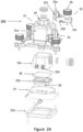
- FIG. 2A to 2E An exemplary embodiment of a modular thermal heat sink device 200 according to the present teaching is shown in each of Figures 2A to 2E .
- the device is modular in that it comprises a number of components that can be releasably secured together to form the totality of the device.
- the housing of the device is modular and comprises a housing assembly and a plurality of removable arms.
- the housing assembly defines a body that comprises various cooling components for operatively effecting cooling of an electronic component on a circuit board, such as the heretofore referenced CPU of Figure 1 .
- the device of the present teaching preferentially uses liquid cooling to effect the operative cooling.
- Liquid cooling is typically achieved by directing a liquid onto a thermal surface or substrate, the movement of the liquid relative to the thermal substrate effecting a cooling effect of that surface.
- the liquid cooling device comprises a thermal cooling plate.
- the thermal cooling plate is configured to be thermally coupled to a thermal substrate which is a surface of an electronic component that requires operative cooling.
- the liquid cooling device further comprises a fluid inlet and a fluid outlet to facilitate fluid circulation to effect the operative cooling of the thermal substrate. For example, this can be achieved through passage of a fluid through an orifice plate. The passed fluid effectively cools the thermal cooling plate which is in thermal contact with the thermal substrate of the electronic component and operatively dissipate heat away from the thermal substrate.
- the impinging jet assembly of Figure 2A comprises a housing assembly.
- the housing assembly may comprise an outer housing 21 and an inner chamber 25 which may also be referred to as a plenum chamber 25.
- the outer housing 21 and the plenum chamber 25 may each define an opening concentric to each other to facilitate a fluid inlet 23.
- the outer housing 21 and the plenum chamber 25 may be releasably coupled together at the fluid inlet 23 to facilitate fluid communication.
- the outer housing 21 may comprise a housing upper portion 21a and a housing lower portion 21b.
- the housing upper portion 21a and the housing lower portion 21b may be releasably engaged with each other to form a liquid-tight engagement which may be referred to as a housing seal.
- the outer housing 21 may optionally be equipped with sealing parts such as an O-ring 27 to enhance the housing seal.
- the outer housing defines a volume to confine the plenum chamber 25.
- the housing upper portion 21a may define another opening to facilitate a fluid outlet 24.
- the housing lower portion 21b may define a thermal cooling plate configured to be in thermal contact with a thermal substrate.
- An example of such a thermal substrate is a top surface of a cooling target electronic component.
- the fluid inlet 23 may be in fluid communication with the plenum chamber 25 which may be referred to as a plenum chamber.
- the plenum chamber 25 may be wholly defined within the outer housing 21.
- the plenum chamber 25 may be a modular chamber in that it may comprise a chamber upper portion 25a and a chamber lower portion 25b.
- the chamber upper portion 25a and the chamber lower portion 25b may be releasably engaged with each other to form a liquid-tight engagement which may be referred to as a chamber seal.
- the plenum chamber 25 may optionally be equipped with sealing parts such as an O-ring 26 to enhance the chamber seal.
- the chamber upper portion 25a may define an opening for facilitating the fluid inlet 23.
- the chamber lower portion 25a may comprise a jet orifice plate which defines a plurality of jet orifices.
- the jet orifices may be distributed across the surface of the jet orifice plate to form an impinging microjet array plate.
- the impinging microjet array provides a fluid outlet through which a pressurised liquid can operably exit the plenum chamber 25.
- the pressurised fluid may contact the thermal cooling plate 21b which is operatively in thermal contact with a thermal substrate, the thermal substrate being a thermal surface of an electronic device.
- the thermal heat sink device operably dissipates heat away from that thermal substrate.
- the impinging jet assembly is configured to operably direct that heated fluid away to exit the assembly via the fluid outlet 24.
- the thermal surface of the electronic device may not be limited to a planar surface. It may comprise one or more raised surfaces or perturbations that operatively increase the area of the contact surface with which the pressurised fluid contacts. These raised surfaces or perturbations may adopt one or more different geometrical forms, such as for example dimples or fins that project upwardly towards the jet orifice plate.
- the housing may define at least one exit channel, the exit channel being configured to deliver fluid exiting the impinging microjet array to the fluid outlet 24. The high velocity of the jets enables the exceptionally high convective heat transfer coefficients to enable highly effective targeted cooling of the electronic component.
- the housing assembly is configured to be mounted over the cooling target of the electronic component.
- the housing assembly can be secured relative to the cooling target through the fixing, engaging, or mounting means according to the various embodiments of the present teaching.
- liquid-based cooling device may include features and components in accordance with those described in published International Patent Application PCT/EP2019/070713 .
- the outer housing 21 shown in Figure 2A forms part of the cooling component in that it serves as the external chamber to facilitate liquid circulation.
- a designated housing which does not necessarily form part of the cooling components essential for facilitating fluid circulation may be provided to enclose the housing assembly.
- the housing may not form part of the components that are required in order to operatively effect the cooling function.
- the housing may serve mainly to secure, protect, and fix the body of the cooling device on a substrate.
- the designated housing may be coupled to the body via suitable mechanical or adhesive coupling means.
- a skilled person should be able to understand and implement such an embodiment based on the present teaching. Such an embodiment is thus not described in detail herewith.
- housing assembly refers to either the housing assembly comprising the outer housing and inner plenum chamber of the thermal sink device or the designated housing within which the body of a thermal heat sink is enclosed.
- the outer housing 21 comprises a plurality of first engaging features spaced about the perimeter of the outer housing 21.
- Each of the plurality of the engaging features of the housing is configured for forming an engagement with an engaging feature 221 of a respective removable arm 22. More specifically, an engaging feature of the housing and the respective engaging feature 221 of a removable arm are dimensioned to cooperate with each other to form an engagement.
- Figure 2A also shows details of an engaging feature 221 of a removable arm 22 according to an embodiment of the present teaching.
- the arm 22 comprises two ends 22a, 22c.
- the engaging feature is defined at one end 22a and is configured to engage with the engaging feature of the housing 21.
- This end 22a of the removable arm 22 may be referred to as a proximal end.
- the other end 22c of the removable arm 22 may be referred to as a distal end.
- the distal end is configured to effect an operative fastening of the arm 22 to a supporting surface on which the modular device is fixed.
- the fastening of the distal end 22c of the removable arm 22 may be effected through application of a force on the distal end 22c.
- the force may be perpendicular to the supporting surface.
- the engaging feature of the housing and the removable arms are configured such that on fixing the device to the supporting surface, the force applied to the distal end 22c of the arm also reinforces the engagement between the proximal end 22a of the arm and the housing 21. The result of this is that the position of the housing 21 is locked by the arms relative to the thermal substrate.
- the modular design of removable arms 22 is advantageous in that the housing of a cooling device can be easily modified by using removable arms of different shapes and dimensions and/or mounting means.
- the compatibility of the cooling device is thus greatly improved, meaning that that it is possible to easily adapt the same cooling device to fit to different computer cards or boards of different designs and layouts.
- a modular design compared with a single-piece design, a modular design inevitably requires additional assembly. This may cause additional disturbance and damaging effect to both the cooling target electronic components and the surrounding electronic components and this is undesirable.
- the present teaching mitigates this potential side effect of a modular design with the unique engagement mechanism between the removable arms and the housing.
- the fastening of the distal ends 22c of the removable arms 22 reinforces both the engagement between the arms 22 and housing 21 as well as the abutment between the rim of housing and the supporting surface. This means that once the modular device has been placed on a circuit board, the placing, securing, locking, and fixing of the entire modular device can be effected by a single step of fastening the distal ends 22c of the arms 22 on to the mounting surface. As a result, disturbance to the various electronic components on the circuit board is minimized. Further details of the removable arms and the engaging features will be described in the subsequent paragraphs.
- the engaging feature of the housing 21 defines a projection and the engaging feature 221 of the removable arm 22 defines a recess.
- the projection and the recess are dimensioned to cooperate and form an engagement with each other.
- the engaging feature 221 of the removable arm 22 defines a projection and the engaging feature of the housing 21 defines a recess.
- the projection and the recess are dimensioned such that a formed engagement between the engaging feature of the housing and that of a respective removable arm locks the position of the respective removable arm 22 relative to the housing 21.
- the recess may be a groove.
- the groove may be a blind groove having a stop end and a through end.
- the projection may comprise a free end configured to fit and abut the stop end of the blind groove.
- the groove and the projection are each dimensioned to form an elongated shape defining a longitudinal axis substantially perpendicular to the thermal cooling plate of the heat sink device.
- the engagement between the projection and the groove may be a sliding engagement along the longitudinal axis.
- the free end and the stop end are configured to form an engagement for preventing lateral displacement between the housing and respective removable arm.
- the free end of the projection and the stop end of the blind groove may be configured to form a pair of complimenting L-shaped locking features so as to prevent lateral displacement along the direction as indicated by the double-ended arrow.
- the inset of Figure 2C shows a magnified view at a vertical cross section along the centreline of the removable arm. As shown in the inset, the L-shaped end of each of the projection and the groove cooperate with each other to form a lock to prevent lateral displacement between the housing and the removable arm in the direction indicated by the double-ended arrow.
- the rim of the housing 21 may have an external flange 213.
- Each removable arm 22 may comprise a middle portion 22b defined between the proximal and distal ends 22a, 22c.
- the middle portion 22b is configured such that on fixing the device, a lower surface of the middle portion 22b of the arm abuts an upper surface of the flange 213 of the housing.
- a force applied to the distal end 22c of each of the removable arms 22 causes the lower surface of the middle portion 22b to press against the upper surface of the flange 213 and in turn reinforces the liquid-tight abutment formed between the housing 21 and the supporting surface.
- the through end of the blind groove abuts the upper surface of the flange 213.
- the stop end of the blind groove is positioned such that a force applied to the distal end 22c of the arm 22 causes the stop end of the groove to press against the free end of the projection.
- the arm 22 has an engaging feature 221 of a blind groove with the stop end positioned at the top and the through end at the bottom.
- the groove may slidably engage with the projection of the housing 21.
- the projection may have one free end, being the upper end in this example. Alternatively, the projection may have two free ends, the upper and lower free ends.
- the engaging feature of the housing defines a recess, i.e. a groove
- the engaging feature of the arm defines a projection.
- the through end of the groove is positioned at the top and the stop end of the groove is position at the bottom.
- the engaging feature 221 of the removable arm defines a groove and the engaging feature of the housing defines a projection
- the through-end of the groove abuts the supporting surface or preferably the flange 213 of the housing to further reinforce the abutment between the housing 21 and the supporting surface.
- the outer housing 21 is a modular housing in that it comprises a housing upper portion 21a and a housing lower portion 21b.
- a modular housing design makes the heat sink device more versatile in that the user can change the thermal cooling plate 21b to modify or tune the thermal conductive property to suit various cooling applications.
- the housing upper portion 21a is configured to engage with the housing lower portion 21b at a rim of the housing upper portion 21a to form a liquid tight engagement or seal.
- the seal may be further improved by using sealing parts such as an O-ring 27.
- the outer housing 21 By fastening each of the arms 22 on or over a supporting surface, the outer housing 21 can be secured over the thermal surface of a cooling target to facilitate forming of a desired thermal coupling.
- the thermal coupling may be enhanced through using a thermal interface material (TIM).
- TIM thermal interface material
- a further advantageous effect simultaneously achieved by the fastening of the arms 22 on or over the supporting surface is that the housing liquid-tight seal formed between the housing upper portion 21a and the housing lower portion 21b is reinforced.
- the fastening of the arms 22 on or over the supporting surface thus not only secures the position of the housing 21 on the supporting surface but also ensures the liquid-tight seal of the housing 21.
- the housing assembly may further comprise an inner plenum chamber 25.
- the plenum chamber 25 and the outer housing 21 may be releasably coupled/engaged with each other.
- the coupling/engagement between the plenum chamber 25 and the outer housing 21 may be achieved via various means.
- the plenum chamber 25 has one or more shoulder features 253. These shoulder features 253 are configured to abut one or more corresponding recess features of the housing upper portion 21a.
- the formed abutment restricts upward movement of the plenum chamber 25. Accordingly, by fixing the removal arms 22 on or over a supporting surface, both the outer housing 21 and the plenum chamber 25 are simultaneously fixed.
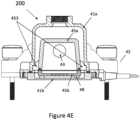
- the abutment formed between the plenum chamber 25 and the outer housing 21 may be better shown in the sectional view of Figure 4E and will thus be described further in the context of the embodiment of Figures 4A to 4E .
- the inner plenum chamber 25 may be modular in that the chamber comprises a chamber upper portion 25a and a chamber lower portion 25b.
- the chamber upper and lower portions 25a, 25b are configured to releasably engaged with each other to form a chamber liquid-tight seal.
- the chamber liquid-tight seal is formed along the rim of the chamber upper portion 25a.
- the seal may be enhanced by sealing components such as an O-ring 26.
- the chamber lower portion 25b comprises an impinging jet plate defining an impinging jet array.
- the impinging jet plate is configured to facilitate passage of a cooling fluid to effect an operative cooling.
- the liquid that has passed the impinging jet array is in thermal contact with the thermal cooling plate defined by lower portion 21b of the outer housing 21.
- the plenum chamber 25 is configured such that on fixing the device to the supporting surface through application of a force on the distal ends 22c of the removable arms 22, the chamber formed between the chamber upper and lower portions 25a, 25b is simultaneously reinforced.
- the effective cooling area offered by the heat sink device may be defined by the arrangement of the impinging jet array of the orifice plate 25b.
- the effective cooling area of the heat sink device may be configured to substantially overlap the cooling target which is a thermal substrate of an electronic component to achieve an effective targeted cooling.
- electronic components may adopt various designs and thus may have thermal substrates of various sizes and/or shapes.
- the modular plenum chamber 25 of the present teaching thus has the advantage of being capable of easily modified for cooling thermal substrates of different shapes and sizes. This can be achieved by simply replacing the lower portion 25b of the plenum chamber 25 with one having jet array of a suitable design. The remaining components of the modular heat sink device may remain unchanged.
- the heat sink device can thus be easily adapted to suit different electronic components in a flexible and cost-effective manner.
- the housing assembly may comprise one or more spacers 28 provided between the chamber lower portion 25b and the housing lower portion 21b.
- the one or more spaces 28 are arranged to create a gap for facilitating a flow of the fluid that has passed through the orifice plate or impinging jet plate.
- the one or more spacers 28 also function to assist the reinforcement of the chamber seal by pressing the chamber lower portion 25b upwardly against the chamber upper portion 25a.
- the plenum chamber 25 may be a single piece component.
- the spacers 28 may be omitted as the single piece chamber 25 may be secured in place solely through a suitable coupling with the outer housing 21.
- the modular heat sink device according to the present teaching can be fixed to a supporting surface through application of a force on the distal ends 22c of the removable arms 22.
- several fixing and reinforcing effects are simultaneously achieved, including at least reinforcing the engagement between the removable arms 22 and the housing 21, reinforcing the coupling between the housing 21 and the plenum chamber 25, reinforcing the liquid-tight housing seal of the housing 21, and reinforcing the liquid-tight chamber seal of the plenum chamber 25.
- a fixing and securing of the device over a cooling target can thus be achieved with minimal fastening procedure causing minimal disturbance to not only the heat sink device itself, but also the cooling target electronic component and the surrounding electronic component on the PCB.
- each arm 22 adopts substantially a straight profile.
- the four arms 22 extend substantially radially from the centre of the housing 21.
- the removable arms may not adopt other shapes.
- the shape and/or dimension of the removable arms may be different even for a single thermal heat sink device.
- at least one of the removable arms may adopt a shape or dimension that is different from the others.
- Figures 3A to 3D show an embodiment of a device which may have similar housing and removable arm engaging features as those described in connection with Figures 2A to 2D .
- the removable arms 32 of each of Figures 3A to 3D are configured to adopt different shapes.
- each of the arms 32 has an angled profile instead of the straight profile of the embodiment as shown in Figure 2D .
- the device On effecting engagements between the arms 32 and the housing 31, the device has a footprint of a different shape compared with that of the embodiment depicted in Figures 2A to 2E . Therefore, by using removable arms of various shapes and/or dimensions, it is possible to adapt the cooling device to suit various circuit board layouts to effect mounting that otherwise wouldn't be possible with the existing thermal heat sink device designs. Versatility and compatibility of the cooling device is therefore greatly improved by adopting the modular design with removable arms according to the present teaching.
- a device according to the present teaching may comprise other number of removable arms. Different numbers of removable arms may be adopted to suit different shapes of the housing for cooling electronic components of other surface profile. Different number of removable arms may also be adopted to suit different circuit board designs or layouts.
- the housing 21, 31 may comprise a number of redundant engaging features, meaning that on mounting the device, only a subset of the total number of engaging features (primary engaging features) are used to effect a particular mounting.
- the remaining engaging features that are redundant in effecting this particular mounting may serve as auxiliary engaging features in the event one or more primary engaging features fail.
- the redundant engaging features that serve as secondary engaging features in effecting one mounting may server as the primary engaging features in effecting a different mounting.
- a different mounting may occur when, for example, effecting a mounting for cooling a different electronic component or on a different mounting surface with a different mounting layout.
- a user may selectively effect some or all of the engaging features.
- Such a configuration further improves the compatibility and adaptability of the modular device to suit various mounting needs.
- the fixing of the device on the supporting surface is effected through application of a force on the distal end 22c, 32c of each of the arm 22, 32.
- the distal end 22c, 32c of each removable arm 22, 32 may define a means for operatively effecting a fastening of the distal end 22c, 32c on a mounting surface.
- each of the distal ends 22c, 32c defines a mounting hole for receiving a fastener.
- the fastener is a torque screw 29, 39.
- a torque screw allows tightening the screw to a specified torque. Therefore, by using a torque screw, a user can control of the amount of torque applied to ensure that tightening is sufficient but not excessive.
- the electronics on a computer board/card are typically delicate and prone to mechanical damage, a desirable effect achieved by using torch screws is that potential damaging effect on a cooling target electronic component cause by excessive force applied during mounting can be prevented.
- a further advantage of using torque screws is that, as the torque can be set to a specific value or range, it is possible to effect a mounting with a specific tightening force profile across the removable arms of the device. This is particularly useful in achieving a more effective thermal coupling between the cooling surface of the thermal heat sink device and the thermal surface of the cooling target electronic component.
- the engaging features of the present teaching are configured such that the tightening force applied on the distal ends of the removable arm affects the engagement and abutment formed on the proximal ends.
- the engagement and abutment on the proximal ends of the removable arms affects the thermal coupling formed between the cooling device and the cooling target electronic component which ultimately impacts the cooling effectiveness. Therefore, by allowing to control the amount of torque applied for fastening each of the removable arms to a specific value or at least a specific range of values, the thermal coupling between the thermal heat sink device and the electronic component can be improved for an improved cooling effectiveness of the thermal heat sink device.
- a modular heat sink device with a number of additional features configured to further reinforce and secure the engagement described in connection with Figures 2A to 2E or 3A to 3D .
- This further embodiment will be described making reference to Figures 4A to 4E .
- Figure 4C shows a partial sectional view of the device of Figure 4A along a horizontal plane h as indicated in Figure 4A .
- the sectional view shows an engagement formed between the housing 41 and a removable arm 42.
- Figure 4C' shows an amplified portion of the engaging detail of Figure 4C .
- the lower portion of the engaging feature of the housing has a T-rail configuration 412.
- the flange portion of the T-rail is modified to form a half-cylinder shape to accommodate a fastening means such as a threaded screw fastener 450.
- the engaging feature of the removable arm is in a form of a matching recess 422 configured for receiving the T-rail to form a slidable engagement.
- Each of the two ends of the flange portion of the T-rail may be further configured to adopt an L-shaped locking feature 413 for preventing lateral displacement between the housing and the removable arm. This in turn reinforces the engagement formed between the arm and the housing.
- Figure 4D shows a partial sectional view along a vertical plane v1 along the centreline of two opposite removable arms as indicated in Figure 4B .
- Features 411 and 421 are cooperating engaging features for preventing lateral displacement in the radiating direction along the removable arm.
- the threaded screw 450 as already mentioned in connection with Figure 4C' is used to secure the housing upper and lower portions 41a, 41b together.
- Figure 4D further shows a snap fitting clamp 430 between the housing and the removable arm. This snap fitting clamp 430 is configured to prevent vertical displacement between the housing and the arm.
- the housing upper and lower portions 41a, 41b form a liquid-tight housing seal which may be enhanced by an O-ring 47.
- the upper and lower chamber portions 45a, 45b form a liquid-tight chamber seal which may be enhanced by an O-ring 46.
- the chamber lower portion 45b has an orifice plate functioning as an impinging jet plate for passing a cooling fluid.
- the chamber lower portion 45b comprises one or more spacers 48 that are similar to the spacers 28 described in conjunction with Figure 2A .
- the sectional view of Figure 4E shows the abutment formed between the plenum chamber 45 and the outer housing 21.
- the abutment is achieved by the shoulder features 453 of the plenum chamber 45 and the corresponding recess features of the outer housing 41. More specifically, the shoulder features 453 are configured to abut one or more recess features formed close to the rim of the housing upper portion 41a. The formed abutment restricts upward movement of the plenum chamber 45.
- the result of this abutment formed between the plenum chamber 45 and the outer housing 41 is that, by fixing the removal arms 42 on or over a supporting surface, both the outer housing 41 and the plenum chamber 45 are simultaneously fixed.
- the removable arms of the embodiments of Figures 4A to 4E are configured to facilitate fastening using torque screws for achieving advantageous fastening effects similar to those demonstrated earlier.
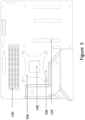
- FIG. 5 shows a simplified schematic diagram of the exemplary CPU card of Figure 1 with a device according to the present teaching mounted over the CPU.
- a server module that comprises side walls defining an enclosure volume within the module within which assorted electronic components typically requires cooling.
- a device such as the present teaching can be provided within the server module enclosure to cool specific ones of the electronic components or could be thermally coupled to the side walls to provide a cooling of the overall module.
Landscapes
- Engineering & Computer Science (AREA)
- Microelectronics & Electronic Packaging (AREA)
- Physics & Mathematics (AREA)
- Thermal Sciences (AREA)
- Theoretical Computer Science (AREA)
- General Engineering & Computer Science (AREA)
- Human Computer Interaction (AREA)
- General Physics & Mathematics (AREA)
- Computer Hardware Design (AREA)
- Cooling Or The Like Of Electrical Apparatus (AREA)
Description
- The present application relates to heat exchangers for cooling computer components.
- Removing waste heat generated by electronic components is critical for ensuring performance of computing systems. Various types of computer coolers have been developed based on different cooling mechanisms. In general, existing coolers are either air-based or liquid-based. Between the two, liquid-based cooling provides advantages over air-based cooling due to better thermophysical properties, such as the higher thermal conductivity, density and specific heat capacity of liquid compared with air. Therefore, liquid-based cooling can provide a more compact cooling solution with higher cooling effectiveness and lower power consumption.
- Some relatively high-powered and computational expensive components such as central processing units (CPUs) and graphics processing units (GPUs) can generate a large amount of heat during operation and thus may require targeted cooling. A CPU forms part of a CPU card and a GPU forms part of a graphics card, both are printed circuit board packed with a large number of electronic across a limited board surface area. The components are further electrically connected using conductive tracks, pads, and other features. Taking a motherboard as an example; it typically comprises at least one CPU chip, various memory chips, memory controllers, input/output systems, and interface connectors, etc. Therefore, it can be challenging to mount a designated cooler for targeted cooling of a specific component on a densely packed computer board or card to achieve the desired cooling effectiveness.
- CPU and GPU chips may adopt various shapes and sizes. To achieve an effective targeted cooling, it is desirable for the cooling device, especially the area where convection cooling is effected to match the shape and size of the heat-dissipating surface of the chips to improve cooling effect and save space.
- Furthermore, printed circuit boards are configured to adopt a large variety of designs, sizes, and/or layouts of components. Again, taking motherboards as an example, a specific type of CPU model may be used in the manufacture of different motherboards. Although a CPU cooler may have been designed to suit the specific CPU model, since the motherboard that holds the CPU may adopt different designs and layouts, especially that of the peripheral components, different fixing or mounting arrangements may be needed.
- Therefore, there exists a need for a cooling device that can be adapted for cooling of electronic components of various shapes and sizes and be compatible with different circuit board designs.
- In addition, in order for a cooling device to achieve the desired cooling effectiveness, a reliable thermal contact with the cooling target component is critical. A reliable thermal contact requires robust and balanced physical coupling between the electronic component and the cooling surface of the cooler. The thermal coupling may be enhanced using a thermal interface material.
- Further issues exist in effecting a robust fixing. Electronic components on a computer board/card are not typically designed to endure high mechanical impacts due to, for example, their delicate features and the fabrication material dictated by functionality. This makes it difficult to robustly mount a cooler without causing damage to or affecting the performance of not only the cooling target component but also its surround electronic components.
- A further issue exists in achieving quality coupling between an electronic component surface and a cooling surface. This is particularly the case if the mounting is performed by consumers which is becoming more common with personalisation of computing equipment in, for example, the gaming industry.
- Therefore, there further exists a need for a cooling device that can be robustly mounted on a circuit board to facilitate required coupling between the component and the cooler to achieve effective cooling performance.
US 2016 327996 describes a cooling module includes: a heat exchanger mounted on an electronic part mounted on a board, and that cools the electronic part; a leaf spring including an overhang portion and an extension portion, the overhang portion overhanging outward beyond the heat exchanger from the heat exchanger, and the extension portion extending from the overhang portion in a direction intersecting an overhang direction of the overhang portion when viewed in a thickness direction of the board; and a support member located around the heat exchanger, and fixed to the board, the extension portion bent toward the board being attached to the support member.US 2010 097766 describes a fixing device for a heat sink.U S2014 150993 describes a base that includes a heat absorber and clips attached to the heat absorber. - The present teaching addresses at least some of the issues that are present in the existing cooling devices.
- The present invention is defined by the independent claims. Further optional features are defined in the dependent claims.
- Accordingly, the present teaching provides a modular liquid-cooled thermal heat sink device configured to thermally engage with a thermal substrate.
- In summary, the device according to the various embodiments described herewith provides a controlled coupling between the heat sink device and the thermal substrate for improved cooling performance. The modular configuration allows the device to be conveniently modified and adapted to suit cooling of electronic components of various sizes or shapes as well as for fitting onto circuit boards of various layouts. The unique fixing and mounting mechanisms facilitate simple and fast fixing of the device with minimal disturbance to both the cooling target electronic component and the surrounding components. The device according to the present teaching thus facilitate improved performance of liquid-based heat sink device for effective targeted cooling of high-powered and computational expensive components such as CPUs and GPUs.
- The present application will now be described with reference to the accompanying drawings in which:
-
Figure 1 is a simplified schematic showing an example of a CPU card holding various electronic components. -
Figure 2A is s a perspective view of a device in accordance with an embodiment of the present teaching with a disengaged arm. -
Figure 2B is a vertical sectional view along a parallel centreline p as indicated inFigure 2D of the device ofFigure 2A . -
Figure 2C is a perspective view of the device ofFigure 2A with all arms engaged. -
Figure 2D is a plan view from above showing the device ofFigure 2A in accordance with an embodiment of the present teaching. -
Figure 2E is a plan view from the bottom showing the device ofFigure 2A in accordance with an embodiment of the present teaching. -
Figure 3A is s a perspective view of a device in accordance with a second embodiment of the present teaching with a disengaged arm. -
Figure 3B is a perspective view of the device ofFigure 3A with all arms engaged. -
Figure 3C is a plan view from above showing the device ofFigure 3A in accordance with an embodiment of the present teaching. -
Figure 3D is a plan view from the bottom showing the device ofFigure 3A in accordance. -
Figure 4A is a side view of a device in accordance with a third embodiment of the present teaching. -
Figure 4B is a plan view from above showing the device ofFigure 4A . -
Figure 4C is a partial horizontal sectional view of the device ofFigure 4A .Figure 4C' is an amplified portion of the view ofFigure 4C . -
Figure 4D is a partial vertical sectional view of the device ofFigure 4A . -
Figure 4E is a vertical sectional view of the device ofFigure 4A . -
Figure 5 is a simplified schematic showing a device according to an embodiment of the present teaching mounted on the CPU card ofFigure 1 . - The present invention will now be exemplified with reference to the accompanying drawings.
- A number of terms used in describing various embodiments of the present invention may be used synonymously or interchangeably. For example, the term "circuit board" may be used synonymously with "printed circuit board", "board", or "motherboard". The term "electronic components" may be used synonymously with "electronics" to refer to various types "integrated circuits", "chips" or any other types of electronic components. The term "thermal heat sink device" may be used synonymously with "heat exchanger" and "cooling device". The term "cooling device", "heat-sink device", or "liquid-based cooler" may be used synonymously with "liquid cooler" or "waterblock". As used herein, and unless the context dictates otherwise, the term "coupled to" or "connected to" is intended to include both direct coupling or connection (in which two elements that are coupled or connected to each other contact each other) and indirect coupling or connection (in which at least one additional element is located between the two elements). Therefore, the terms "coupled to", "coupled with", "connected to" and "connected with" are used synonymously.
- The following discussion provides many exemplary embodiments of the inventive subject matter. Although each embodiment represents a single combination of inventive elements, the inventive subject matter is considered to include all possible combinations of the disclosed elements. Thus, if one embodiment comprises elements A, B, and C, and a second embodiment comprises elements B and D, then the inventive subject matter is also considered to include other remaining combinations of A, B, C, or D, even if not explicitly disclosed.
- For simplicity and clarity of illustration, reference numerals may be repeated among the figures to indicate corresponding or analogous elements. Numerous details are set forth to provide an understanding of the examples described herein. The examples may be practiced without these details. In other instances, well-known methods, procedures, and components are not described in detail to avoid obscuring the examples described. The description is not to be considered as limited to the scope of the examples described herein.
- According to an embodiment of the present teaching, a modular thermal heat sink device or cooling device for cooling electronic components on a circuit board is provided.
Figure 1 shows an example of aconventional circuit board 100 which may be a printed circuit board (PCB) configured as a motherboard. Such aboard 100 is typically provided as a preassembled board that is then fixed within the housing of the computing device. Such a PCB is typically configured to provided one ormore slots 120, such as PCI slots which are dimensioned to receive and retain respective hardware components such as network cards, modems, sound cards, disk controllers and other peripherals. The circuit board may also have directly coupled multiple integrated circuits or chips. Memory such asRAM 130 or ROM may also be provided on the board. Other electronic components that are typically deployed include a central processing unit (CPU), graphics processing unit (GPU) or the like. The specifics of the processing unit deployed with the motherboard will determine the application that it is being used primarily for. These processing units are typically the major source of heat of the motherboard and their performance is related to their operating temperature. For these reasons there is a reason to cool the motherboard and/or specific components of same. The example ofFigure 1 is a motherboard with aCPU 140, the type of which can be effectively cooled using a modular thermal heat sink device according to the present teaching. The use of heat sink devices per se to effect a cooling of aCPU 140 is not new, these devices are typically pre-designed for specific CPUs and are fixed relative to the motherboard usingCPU mounting threads 150. - Per the present teaching, a new type of thermal heat sink devices that can be used with conventional motherboards is provided. An exemplary embodiment of a modular thermal
heat sink device 200 according to the present teaching is shown in each ofFigures 2A to 2E . The device is modular in that it comprises a number of components that can be releasably secured together to form the totality of the device. The housing of the device is modular and comprises a housing assembly and a plurality of removable arms. The housing assembly defines a body that comprises various cooling components for operatively effecting cooling of an electronic component on a circuit board, such as the heretofore referenced CPU ofFigure 1 . - The device of the present teaching preferentially uses liquid cooling to effect the operative cooling. Liquid cooling is typically achieved by directing a liquid onto a thermal surface or substrate, the movement of the liquid relative to the thermal substrate effecting a cooling effect of that surface. For example, the liquid cooling device comprises a thermal cooling plate. The thermal cooling plate is configured to be thermally coupled to a thermal substrate which is a surface of an electronic component that requires operative cooling. The liquid cooling device further comprises a fluid inlet and a fluid outlet to facilitate fluid circulation to effect the operative cooling of the thermal substrate. For example, this can be achieved through passage of a fluid through an orifice plate. The passed fluid effectively cools the thermal cooling plate which is in thermal contact with the thermal substrate of the electronic component and operatively dissipate heat away from the thermal substrate.
- An example of a suitable liquid-based cooler is shown in the exploded view of
Figure 2A as well as the sectional view ofFigure 2B . The sectional view ofFigure 2B shows the cross section of the device ofFigure 2A along a centreline p as indicated in the top view ofFigure 2D . The impinging jet assembly ofFigure 2A comprises a housing assembly. The housing assembly may comprise anouter housing 21 and an inner chamber 25 which may also be referred to as a plenum chamber 25. Theouter housing 21 and the plenum chamber 25 may each define an opening concentric to each other to facilitate afluid inlet 23. Theouter housing 21 and the plenum chamber 25 may be releasably coupled together at thefluid inlet 23 to facilitate fluid communication. - The
outer housing 21 may comprise a housingupper portion 21a and a housinglower portion 21b. The housingupper portion 21a and the housinglower portion 21b may be releasably engaged with each other to form a liquid-tight engagement which may be referred to as a housing seal. Theouter housing 21 may optionally be equipped with sealing parts such as an O-ring 27 to enhance the housing seal. The outer housing defines a volume to confine the plenum chamber 25. The housingupper portion 21a may define another opening to facilitate afluid outlet 24. The housinglower portion 21b may define a thermal cooling plate configured to be in thermal contact with a thermal substrate. An example of such a thermal substrate is a top surface of a cooling target electronic component. - The
fluid inlet 23 may be in fluid communication with the plenum chamber 25 which may be referred to as a plenum chamber. The plenum chamber 25 may be wholly defined within theouter housing 21. In a preferred embodiment, the plenum chamber 25 may be a modular chamber in that it may comprise a chamberupper portion 25a and a chamberlower portion 25b. The chamberupper portion 25a and the chamberlower portion 25b may be releasably engaged with each other to form a liquid-tight engagement which may be referred to as a chamber seal. The plenum chamber 25 may optionally be equipped with sealing parts such as an O-ring 26 to enhance the chamber seal. The chamberupper portion 25a may define an opening for facilitating thefluid inlet 23. The chamberlower portion 25a may comprise a jet orifice plate which defines a plurality of jet orifices. The jet orifices may be distributed across the surface of the jet orifice plate to form an impinging microjet array plate. The impinging microjet array provides a fluid outlet through which a pressurised liquid can operably exit the plenum chamber 25. On exiting the impinging microjet array, the pressurised fluid may contact thethermal cooling plate 21b which is operatively in thermal contact with a thermal substrate, the thermal substrate being a thermal surface of an electronic device. In this way, the thermal heat sink device operably dissipates heat away from that thermal substrate. The impinging jet assembly is configured to operably direct that heated fluid away to exit the assembly via thefluid outlet 24. It will be appreciated that the thermal surface of the electronic device may not be limited to a planar surface. It may comprise one or more raised surfaces or perturbations that operatively increase the area of the contact surface with which the pressurised fluid contacts. These raised surfaces or perturbations may adopt one or more different geometrical forms, such as for example dimples or fins that project upwardly towards the jet orifice plate.To effectively direct the heated fluid away from the thermal substrate of the electronic component, the housing may define at least one exit channel, the exit channel being configured to deliver fluid exiting the impinging microjet array to thefluid outlet 24. The high velocity of the jets enables the exceptionally high convective heat transfer coefficients to enable highly effective targeted cooling of the electronic component. - The housing assembly is configured to be mounted over the cooling target of the electronic component. The housing assembly can be secured relative to the cooling target through the fixing, engaging, or mounting means according to the various embodiments of the present teaching.
- In addition to the features and configurations that will be appreciated from the discussion herein, the liquid-based cooling device may include features and components in accordance with those described in published International Patent Application
PCT/EP2019/070713 - The
outer housing 21 shown inFigure 2A forms part of the cooling component in that it serves as the external chamber to facilitate liquid circulation. It should be noted that a designated housing which does not necessarily form part of the cooling components essential for facilitating fluid circulation may be provided to enclose the housing assembly. In other words, the housing may not form part of the components that are required in order to operatively effect the cooling function. Instead, the housing may serve mainly to secure, protect, and fix the body of the cooling device on a substrate. In such an embodiment, the designated housing may be coupled to the body via suitable mechanical or adhesive coupling means. A skilled person should be able to understand and implement such an embodiment based on the present teaching. Such an embodiment is thus not described in detail herewith. - For simplicity, the following sections adopts the term "housing assembly" to refer to either the housing assembly comprising the outer housing and inner plenum chamber of the thermal sink device or the designated housing within which the body of a thermal heat sink is enclosed.
- Further views of the housing of
Figures 2A and2B are shown inFigures 2C to 2E . Theouter housing 21 comprises a plurality of first engaging features spaced about the perimeter of theouter housing 21. Each of the plurality of the engaging features of the housing is configured for forming an engagement with anengaging feature 221 of a respectiveremovable arm 22. More specifically, an engaging feature of the housing and the respectiveengaging feature 221 of a removable arm are dimensioned to cooperate with each other to form an engagement. The detail of the engaging features and their engaging mechanisms will be described in detail in the following paragraphs. - The exemplary
outer housing 21 shown inFigures 2A to 2D adopts substantially a cuboid shape. Accordingly, the rim of the housing, as shown inFigures 2D and 2E has substantially a rectangular shape. The engaging features of the exemplary housing are arranged at or proximal to the corners of the rectangular rim. It will be appreciated that other suitable shapes may be adopted. The present teaching is not to be construed to be limited by the shape or dimension of the housing. -
Figure 2A also shows details of anengaging feature 221 of aremovable arm 22 according to an embodiment of the present teaching. Thearm 22 comprises twoends end 22a and is configured to engage with the engaging feature of thehousing 21. Thisend 22a of theremovable arm 22 may be referred to as a proximal end. Theother end 22c of theremovable arm 22 may be referred to as a distal end. The distal end is configured to effect an operative fastening of thearm 22 to a supporting surface on which the modular device is fixed. - The fastening of the
distal end 22c of theremovable arm 22 may be effected through application of a force on thedistal end 22c. The force may be perpendicular to the supporting surface. Once each of thearms 22 has formed an engagement with theouter housing 21, by effecting the fastening each of thearms 22 on a supporting surface, theouter housing 21 is effectively fixed to the supporting surface.Figure 2C shows the device ofFigures 2A and2B with engagements formed between all fourarms 22 and thehousing 21.Figures 2D and 2E show the top plan view and bottom plan view respectively of the same device with all fourarms 22 engaged with thehousing 21. - According to an embodiment of the present teaching, the engaging feature of the housing and the removable arms are configured such that on fixing the device to the supporting surface, the force applied to the
distal end 22c of the arm also reinforces the engagement between theproximal end 22a of the arm and thehousing 21. The result of this is that the position of thehousing 21 is locked by the arms relative to the thermal substrate. - Compared with a single-piece design, the modular design of
removable arms 22 is advantageous in that the housing of a cooling device can be easily modified by using removable arms of different shapes and dimensions and/or mounting means. The compatibility of the cooling device is thus greatly improved, meaning that that it is possible to easily adapt the same cooling device to fit to different computer cards or boards of different designs and layouts. However, compared with a single-piece design, a modular design inevitably requires additional assembly. This may cause additional disturbance and damaging effect to both the cooling target electronic components and the surrounding electronic components and this is undesirable. - The present teaching mitigates this potential side effect of a modular design with the unique engagement mechanism between the removable arms and the housing. As previously described, the fastening of the distal ends 22c of the
removable arms 22 reinforces both the engagement between thearms 22 andhousing 21 as well as the abutment between the rim of housing and the supporting surface. This means that once the modular device has been placed on a circuit board, the placing, securing, locking, and fixing of the entire modular device can be effected by a single step of fastening the distal ends 22c of thearms 22 on to the mounting surface. As a result, disturbance to the various electronic components on the circuit board is minimized. Further details of the removable arms and the engaging features will be described in the subsequent paragraphs. - Again with reference to
Figure 2A , a specific exemplary configuration of the engaging features of the housing and the removable arms is described herewith. In this particular embodiment, the engaging feature of thehousing 21 defines a projection and theengaging feature 221 of theremovable arm 22 defines a recess. The projection and the recess are dimensioned to cooperate and form an engagement with each other. In an alternative embodiment, theengaging feature 221 of theremovable arm 22 defines a projection and the engaging feature of thehousing 21 defines a recess. - Preferably, the projection and the recess are dimensioned such that a formed engagement between the engaging feature of the housing and that of a respective removable arm locks the position of the respective
removable arm 22 relative to thehousing 21. - According to some embodiments, the recess may be a groove. The groove may be a blind groove having a stop end and a through end. The projection may comprise a free end configured to fit and abut the stop end of the blind groove. Preferably, the groove and the projection are each dimensioned to form an elongated shape defining a longitudinal axis substantially perpendicular to the thermal cooling plate of the heat sink device. The engagement between the projection and the groove may be a sliding engagement along the longitudinal axis. In a particular embodiment, the free end and the stop end are configured to form an engagement for preventing lateral displacement between the housing and respective removable arm. For example, the free end of the projection and the stop end of the blind groove may be configured to form a pair of complimenting L-shaped locking features so as to prevent lateral displacement along the direction as indicated by the double-ended arrow. The inset of
Figure 2C shows a magnified view at a vertical cross section along the centreline of the removable arm. As shown in the inset, the L-shaped end of each of the projection and the groove cooperate with each other to form a lock to prevent lateral displacement between the housing and the removable arm in the direction indicated by the double-ended arrow. - As shown in
Figure 2A , the rim of thehousing 21 may have anexternal flange 213. Eachremovable arm 22 may comprise amiddle portion 22b defined between the proximal anddistal ends middle portion 22b is configured such that on fixing the device, a lower surface of themiddle portion 22b of the arm abuts an upper surface of theflange 213 of the housing. A force applied to thedistal end 22c of each of theremovable arms 22 causes the lower surface of themiddle portion 22b to press against the upper surface of theflange 213 and in turn reinforces the liquid-tight abutment formed between thehousing 21 and the supporting surface. - According to some embodiments, on fixing the device to a supporting surface, the through end of the blind groove abuts the upper surface of the
flange 213. The stop end of the blind groove is positioned such that a force applied to thedistal end 22c of thearm 22 causes the stop end of the groove to press against the free end of the projection. Take again the device shown inFigure 2A as an example, thearm 22 has anengaging feature 221 of a blind groove with the stop end positioned at the top and the through end at the bottom. The groove may slidably engage with the projection of thehousing 21. The projection may have one free end, being the upper end in this example. Alternatively, the projection may have two free ends, the upper and lower free ends. In any case, when theengaging feature 221 of the arm and that of the housing are engaged, a fastening force applied to thedistal end 22c of thearm 22 will cause the stop end of the groove of the arm to press against the upper free end of the projection feature of thehousing 21. According to some alternative embodiments, the engaging feature of the housing defines a recess, i.e. a groove, and the engaging feature of the arm defines a projection. In such embodiments, the through end of the groove is positioned at the top and the stop end of the groove is position at the bottom. On fixing the device to the supporting surface, a force applied to thedistal end 22c of thearm 22 will cause the lower free end of the projection to press against the stop end of the blind groove. - In the embodiments where the
engaging feature 221 of the removable arm defines a groove and the engaging feature of the housing defines a projection, on fixing the device to the supporting surface, the through-end of the groove abuts the supporting surface or preferably theflange 213 of the housing to further reinforce the abutment between thehousing 21 and the supporting surface. - According to a preferred embodiment, the
outer housing 21 is a modular housing in that it comprises a housingupper portion 21a and a housinglower portion 21b. Such a modular housing design makes the heat sink device more versatile in that the user can change thethermal cooling plate 21b to modify or tune the thermal conductive property to suit various cooling applications. The housingupper portion 21a is configured to engage with the housinglower portion 21b at a rim of the housingupper portion 21a to form a liquid tight engagement or seal. The seal may be further improved by using sealing parts such as an O-ring 27. By fastening each of thearms 22 on or over a supporting surface, theouter housing 21 can be secured over the thermal surface of a cooling target to facilitate forming of a desired thermal coupling. The thermal coupling may be enhanced through using a thermal interface material (TIM). - A further advantageous effect simultaneously achieved by the fastening of the
arms 22 on or over the supporting surface is that the housing liquid-tight seal formed between the housingupper portion 21a and the housinglower portion 21b is reinforced. The fastening of thearms 22 on or over the supporting surface thus not only secures the position of thehousing 21 on the supporting surface but also ensures the liquid-tight seal of thehousing 21. - As described earlier, the housing assembly may further comprise an inner plenum chamber 25. The plenum chamber 25 and the
outer housing 21 may be releasably coupled/engaged with each other. The coupling/engagement between the plenum chamber 25 and theouter housing 21 may be achieved via various means. In one embodiment, as one can see from the exploded view ofFigure 2A , the plenum chamber 25 has one or more shoulder features 253. These shoulder features 253 are configured to abut one or more corresponding recess features of the housingupper portion 21a. The formed abutment restricts upward movement of the plenum chamber 25. Accordingly, by fixing theremoval arms 22 on or over a supporting surface, both theouter housing 21 and the plenum chamber 25 are simultaneously fixed. The abutment formed between the plenum chamber 25 and theouter housing 21 may be better shown in the sectional view ofFigure 4E and will thus be described further in the context of the embodiment ofFigures 4A to 4E . - According to an embodiment, the inner plenum chamber 25 may be modular in that the chamber comprises a chamber
upper portion 25a and a chamberlower portion 25b. The chamber upper andlower portions Figure 2A , the chamber liquid-tight seal is formed along the rim of the chamberupper portion 25a. The seal may be enhanced by sealing components such as an O-ring 26. The chamberlower portion 25b comprises an impinging jet plate defining an impinging jet array. The impinging jet plate is configured to facilitate passage of a cooling fluid to effect an operative cooling. For example, the liquid that has passed the impinging jet array is in thermal contact with the thermal cooling plate defined bylower portion 21b of theouter housing 21. - According to an embodiment, the plenum chamber 25 is configured such that on fixing the device to the supporting surface through application of a force on the distal ends 22c of the
removable arms 22, the chamber formed between the chamber upper andlower portions - The effective cooling area offered by the heat sink device may be defined by the arrangement of the impinging jet array of the
orifice plate 25b. The effective cooling area of the heat sink device may be configured to substantially overlap the cooling target which is a thermal substrate of an electronic component to achieve an effective targeted cooling. In practice, electronic components may adopt various designs and thus may have thermal substrates of various sizes and/or shapes. The modular plenum chamber 25 of the present teaching thus has the advantage of being capable of easily modified for cooling thermal substrates of different shapes and sizes. This can be achieved by simply replacing thelower portion 25b of the plenum chamber 25 with one having jet array of a suitable design. The remaining components of the modular heat sink device may remain unchanged. The heat sink device can thus be easily adapted to suit different electronic components in a flexible and cost-effective manner. - The housing assembly may comprise one or
more spacers 28 provided between the chamberlower portion 25b and the housinglower portion 21b. The one ormore spaces 28 are arranged to create a gap for facilitating a flow of the fluid that has passed through the orifice plate or impinging jet plate. The one ormore spacers 28 also function to assist the reinforcement of the chamber seal by pressing the chamberlower portion 25b upwardly against the chamberupper portion 25a. - It should be noted that in some alternative embodiments, the plenum chamber 25 may be a single piece component. In such embodiments, the
spacers 28 may be omitted as the single piece chamber 25 may be secured in place solely through a suitable coupling with theouter housing 21. - As described earlier, the modular heat sink device according to the present teaching can be fixed to a supporting surface through application of a force on the distal ends 22c of the
removable arms 22. Advantageously, on fixing the device to the supporting surface, several fixing and reinforcing effects are simultaneously achieved, including at least reinforcing the engagement between theremovable arms 22 and thehousing 21, reinforcing the coupling between thehousing 21 and the plenum chamber 25, reinforcing the liquid-tight housing seal of thehousing 21, and reinforcing the liquid-tight chamber seal of the plenum chamber 25. A fixing and securing of the device over a cooling target can thus be achieved with minimal fastening procedure causing minimal disturbance to not only the heat sink device itself, but also the cooling target electronic component and the surrounding electronic component on the PCB. - In the exemplary embodiment shown in
Figures 2A to 2E , the fourarms 22 are configured to adopt the same shape and dimension. As one can see from the top plan view ofFigure 2D , each arm adopts substantially a straight profile. On forming engagements with the housing, the fourarms 22 extend substantially radially from the centre of thehousing 21. - According to some embodiments, the removable arms may not adopt other shapes. Furthermore, the shape and/or dimension of the removable arms may be different even for a single thermal heat sink device. For example, at least one of the removable arms may adopt a shape or dimension that is different from the others.
Figures 3A to 3D show an embodiment of a device which may have similar housing and removable arm engaging features as those described in connection withFigures 2A to 2D . However, theremovable arms 32 of each ofFigures 3A to 3D are configured to adopt different shapes. - The difference in the shape of the removable arms may be more easily perceivable from the top plan view shown in
Figure 3C . As one can see fromFigure 3C , each of thearms 32 has an angled profile instead of the straight profile of the embodiment as shown inFigure 2D . On effecting engagements between thearms 32 and thehousing 31, the device has a footprint of a different shape compared with that of the embodiment depicted inFigures 2A to 2E . Therefore, by using removable arms of various shapes and/or dimensions, it is possible to adapt the cooling device to suit various circuit board layouts to effect mounting that otherwise wouldn't be possible with the existing thermal heat sink device designs. Versatility and compatibility of the cooling device is therefore greatly improved by adopting the modular design with removable arms according to the present teaching. - Although exemplified with four removable arms, a device according to the present teaching may comprise other number of removable arms. Different numbers of removable arms may be adopted to suit different shapes of the housing for cooling electronic components of other surface profile. Different number of removable arms may also be adopted to suit different circuit board designs or layouts.
- In yet some further embodiments, the
housing - As aforementioned, the fixing of the device on the supporting surface is effected through application of a force on the
distal end arm distal end removable arm distal end - According to an embodiment, as shown in any of
Figures 2A to 2E , and 3A to 3D, each of the distal ends 22c, 32c defines a mounting hole for receiving a fastener. In a preferred embodiment, the fastener is atorque screw - As described earlier, the engaging features of the present teaching are configured such that the tightening force applied on the distal ends of the removable arm affects the engagement and abutment formed on the proximal ends. As described earlier, the engagement and abutment on the proximal ends of the removable arms affects the thermal coupling formed between the cooling device and the cooling target electronic component which ultimately impacts the cooling effectiveness. Therefore, by allowing to control the amount of torque applied for fastening each of the removable arms to a specific value or at least a specific range of values, the thermal coupling between the thermal heat sink device and the electronic component can be improved for an improved cooling effectiveness of the thermal heat sink device.
- In a further embodiment according to the present teaching, there is provided a modular heat sink device with a number of additional features configured to further reinforce and secure the engagement described in connection with
Figures 2A to 2E or3A to 3D . This further embodiment will be described making reference toFigures 4A to 4E . -
Figure 4A shows a side view of a device in accordance with such a further embodiment. As one can see, the modular heat sink device shown inFigure 4A is similar to that shown inFigures 2A to 2E . However, a difference exists in that, the removable arms of the device ofFigure 4A have raisedside walls 410 along either side extending from the proximal end to the distal end of the removable arm. The raised side walls provide additional strength to the removable arms. Apart from these raised side walls, the exterior configuration of the device ofFigure 4A is substantially the same as that ofFigures 2A to 2E . Accordingly, the top plan views of the two embodiments as shown inFigure 2D andFigure 4B are substantially the same. - In addition to the raised side walls, the embodiment shown in
Figures 4A and 4B has a number of further engaging details compared with that ofFigures 2A to 2E . These further engaging details are described below in connection with the sectional views shown inFigures 4C and 4D. Figure 4C shows a partial sectional view of the device ofFigure 4A along a horizontal plane h as indicated inFigure 4A . The sectional view shows an engagement formed between thehousing 41 and aremovable arm 42.Figure 4C' shows an amplified portion of the engaging detail ofFigure 4C . In this particular embodiment, the lower portion of the engaging feature of the housing has a T-rail configuration 412. The flange portion of the T-rail is modified to form a half-cylinder shape to accommodate a fastening means such as a threadedscrew fastener 450. The engaging feature of the removable arm is in a form of amatching recess 422 configured for receiving the T-rail to form a slidable engagement. Each of the two ends of the flange portion of the T-rail may be further configured to adopt an L-shapedlocking feature 413 for preventing lateral displacement between the housing and the removable arm. This in turn reinforces the engagement formed between the arm and the housing. -
Figure 4D shows a partial sectional view along a vertical plane v1 along the centreline of two opposite removable arms as indicated inFigure 4B .Features screw 450 as already mentioned in connection withFigure 4C' is used to secure the housing upper andlower portions Figure 4D further shows a snapfitting clamp 430 between the housing and the removable arm. This snapfitting clamp 430 is configured to prevent vertical displacement between the housing and the arm. - The remaining features shown in
Figure 4D are substantially similar to those of the embodiment ofFigure 2A . For example, the housing upper andlower portions ring 47. Similarly, the upper andlower chamber portions ring 46. The chamberlower portion 45b has an orifice plate functioning as an impinging jet plate for passing a cooling fluid. The chamberlower portion 45b comprises one ormore spacers 48 that are similar to thespacers 28 described in conjunction withFigure 2A . - As mentioned earlier, the sectional view of
Figure 4E shows the abutment formed between the plenum chamber 45 and theouter housing 21. The abutment is achieved by the shoulder features 453 of the plenum chamber 45 and the corresponding recess features of theouter housing 41. More specifically, the shoulder features 453 are configured to abut one or more recess features formed close to the rim of the housingupper portion 41a. The formed abutment restricts upward movement of the plenum chamber 45. The result of this abutment formed between the plenum chamber 45 and theouter housing 41 is that, by fixing theremoval arms 42 on or over a supporting surface, both theouter housing 41 and the plenum chamber 45 are simultaneously fixed. - It should be noted that the above described additional engaging details may be combined, individually or in combination, with the embodiment of
Figures 2A to 2E orFigures 3A to 3D to form further functioning embodiments. - Preferably, similar to the embodiments described earlier, the removable arms of the embodiments of
Figures 4A to 4E are configured to facilitate fastening using torque screws for achieving advantageous fastening effects similar to those demonstrated earlier. -
Figure 5 shows a simplified schematic diagram of the exemplary CPU card ofFigure 1 with a device according to the present teaching mounted over the CPU. - Whilst the present teaching has been exemplified with reference to dissipating heat away from an electronic component, it will be appreciated that any heated surface that requires cooling can benefit from the present teaching. In this way for example, a server module that comprises side walls defining an enclosure volume within the module within which assorted electronic components typically requires cooling. A device such as the present teaching can be provided within the server module enclosure to cool specific ones of the electronic components or could be thermally coupled to the side walls to provide a cooling of the overall module.
- The words comprises/comprising when used in this specification are to specify the presence of stated features, integers, steps or components but does not preclude the presence or addition of one or more other features, integers, steps, components or groups thereof.
Claims (12)
- A modular liquid-cooled thermal heat sink device (200) configured to thermally engage with a thermal substrate, the device comprising:a housing assembly having a body defining a volume, the housing assembly comprising a thermal cooling plate (21b) configured to be in thermal contact with the thermal substrate, a fluid inlet (23) and a fluid outlet, (24) the housing assembly being configured to facilitate fluid circulation within the body to effect an operative cooling of the thermal substrate through the thermal cooling plate (21b), the body comprising a plurality of first engaging features spaced about a perimeter of the body;a plurality of removable arms (22) each comprising a first (22a) and second end (22c), each of the plurality of arms (22) being configured to mate with the body at a respective one of the plurality of first engaging features, wherein each of the first ends (22a) defines a second engaging feature dimensioned to cooperate and form an engagement with a respective first engaging feature, and wherein each of the second ends (22c) is configured to effect an operative fixing of the device (200) to a supporting surface through application of a force on each of the second ends (22c),the force being perpendicular to the supporting surface;wherein each of the first and second engaging features are configured such that, on fixing the device (200) to the supporting surface, the force reinforces the engagement between the arms (22) and the body;the housing assembly further comprising an outer housing (21) and an inner chamber (25), the outer housing (21) defining the body, the inner chamber (25) being configured to detachably couple to the outer housing (21), wherein the body of the outer housing (21) comprises a housing upper portion (21a) and a housing lower portion (21b), the housing lower portion (21b) comprising the thermal cooling plate (21b), the housing upper (21a) and lower (21b) portions being configured to releasably engage with each other to form a housing liquid-tight engagement, and wherein on fixing the device (200) to the supporting surface, the force reinforces the housing liquid-tight engagement formed between the housing upper (21a) and lower (21b) portions;further wherein the inner chamber comprises a chamber upper portion (25a) and a chamber lower portion (25b) configured to releasably engage with each other to form a chamber liquid-tight engagement, the chamber lower portion (25b) comprising an orifice region configured to facilitate passage of a fluid to be in thermal contact with the thermal cooling plate (21b) to effect the operative cooling, and wherein the inner chamber (25) and the outer housing (21) are releasably coupled to each other such that, on fixing the device (200) to the supporting surface, the force reinforces the chamber liquid-tight engagement formed between the chamber upper (25a) and lower (25b) portions:further comprising one or more spacers (28) between the chamber lower portion (25b) and the housing lower portion (21b) to create a gap for facilitating a flow of the fluid that has passed through the orifice region, the one or more spacers (28) configured to facilitate the reinforcement of the chamber liquid-tight engagement; andwherein the orifice region defines an effective cooling region, the effective cooling region is dimensioned to substantially overlap the surface area of the thermal substrate, andwherein the cooling fluid enters the inner chamber (25) through the fluid inlet (23) and leaves the outer housing (21) through the fluid outlet (24).
- The device of claim 1, wherein each second engaging feature defines a groove and the first engaging feature defines a projection dimensioned to be at least partially received within the groove.
- The device of claim 1, wherein each second engaging feature defines a projection and the first engagement feature defines a groove dimensioned to receive the projection.
- The device of claim 2 or claim 3, wherein the groove and the projection are dimensioned such that the formed engagement locks the position of the respective arm relative to the housing assembly.
- The device of any of claims 2 to 4, wherein:the groove is a blind groove comprising a stop end and a through end; andthe projection comprises a free end configured to fit and abut the stop end of the blind groove, the groove and the projection being configured such that on fixing the device to the supporting surface, the force causes the stop end of the blind groove and the free end of the projection to press against each other to reinforce the engagement formed between the respective arm and the body.
- The device of any of claims 2 to 5, the groove and the projection each dimensioned to form an elongated shape defining a longitudinal axis substantially perpendicular to the thermal cooling plate, wherein the engagement is a slidable engagement between the projection and the groove along the longitudinal axis.
- The device of any preceding claim, wherein the application of the force on each of the second ends of the plurality of removable arms is effected by a respective torque screw of a plurality of torque screws.
- The device of claim 7, wherein the plurality of torque screws are configured to operatively tighten to a specific torque.
- The device of claim 7 or 8, wherein:a first torque screw of the plurality of torque screws is configured to be tightened to a first specific torque; anda second torque screw of the plurality of torque screws is configured to be tightened to a second specific torque different from the first torque.
- The device of any preceding claim, wherein upon fixing the housing assembly to the supporting surface to facilitate a thermal contact between the thermal cooling plate and the thermal substrate, a lower surface of each removable arm is suspended over the supporting surface.
- The device of claim 10, wherein:the housing upper portion comprises an external flange along the rim of the outer housing; andeach of the plurality of removable arms comprises a middle portion defined between the first end and second end, the middle portion configured such that on effecting the operative fixing of the device to the supporting surface, a lower surface of the middle portion presses against an upper surface of the external flange to simultaneously effect the reinforcement defined in claim 1.
- The device of any preceding claim, wherein at least two of the plurality of arms are in different shape and/or dimensions.
Applications Claiming Priority (2)
| Application Number | Priority Date | Filing Date | Title |
|---|---|---|---|
| GB2018706.8A GB2601357B (en) | 2020-11-27 | 2020-11-27 | Modular thermal heat sink device |
| PCT/EP2021/082822 WO2022112329A1 (en) | 2020-11-27 | 2021-11-24 | Modular thermal heat sink device |
Publications (3)
| Publication Number | Publication Date |
|---|---|
| EP4252498A1 EP4252498A1 (en) | 2023-10-04 |
| EP4252498B1 true EP4252498B1 (en) | 2025-04-23 |
| EP4252498C0 EP4252498C0 (en) | 2025-04-23 |
Family
ID=74099927
Family Applications (1)
| Application Number | Title | Priority Date | Filing Date |
|---|---|---|---|
| EP21819812.5A Active EP4252498B1 (en) | 2020-11-27 | 2021-11-24 | Modular thermal heat sink device |
Country Status (4)
| Country | Link |
|---|---|
| US (1) | US12063756B2 (en) |
| EP (1) | EP4252498B1 (en) |
| GB (1) | GB2601357B (en) |
| WO (1) | WO2022112329A1 (en) |
Families Citing this family (24)
| Publication number | Priority date | Publication date | Assignee | Title |
|---|---|---|---|---|
| US11042406B2 (en) | 2018-06-05 | 2021-06-22 | Intel Corporation | Technologies for providing predictive thermal management |
| US11917790B2 (en) | 2019-04-26 | 2024-02-27 | Intel Corporation | Thermal control for processor-based devices |
| US11678444B2 (en) | 2019-05-15 | 2023-06-13 | Intel Corporation | Loading mechanism with integrated heatsink |
| US11842943B2 (en) | 2019-08-06 | 2023-12-12 | Intel Corporation | Electronic systems with inverted circuit board with heat sink to chassis attachment |
| US12082370B2 (en) | 2020-06-03 | 2024-09-03 | Intel Corporation | System device aggregation in a liquid cooling environment |
| US12133357B2 (en) | 2020-06-08 | 2024-10-29 | Intel Corporation | Cold plate architecture for liquid cooling of devices |
| US20220015262A1 (en) | 2020-07-09 | 2022-01-13 | Intel Corporation | Technologies for dynamic cooling in a multi-chip package with programmable impingement valves |
| US12063759B2 (en) | 2020-07-13 | 2024-08-13 | Intel Corporation | Conformable cold plate for fluid cooling applications |
| US12293956B2 (en) | 2020-07-31 | 2025-05-06 | Intel Corporation | Boiling enhancement structures for immersion cooled electronic systems |
| US12169180B2 (en) | 2020-12-23 | 2024-12-17 | Intel Corporation | Optical leak detection of liquid cooling components within an electronic system |
| US12442712B2 (en) | 2020-12-23 | 2025-10-14 | Intel Corporation | Liquid cooling system leak detection improvements |
| US12055986B2 (en) | 2021-02-26 | 2024-08-06 | Intel Corporation | Flexible and modular top and bottom side processor unit module cooling |
| US12191230B2 (en) | 2021-03-26 | 2025-01-07 | Intel Corporation | Technologies for liquid cooling systems |
| US12248344B2 (en) | 2021-03-26 | 2025-03-11 | Intel Corporation | Technologies for liquid cooling interfaces |
| US12309966B2 (en) | 2021-06-30 | 2025-05-20 | Intel Corporation | Thermally conductive chamber with stiffening structure for thermal cooling assembly of semiconductor chip package under high loading force |
| US12262478B2 (en) | 2021-09-13 | 2025-03-25 | Intel Corporation | Selectively applied protective layer on exposed materials of electronic circuit board and electronic components disposed thereon for immersion bath cooled systems |
| US12279395B2 (en) | 2021-09-14 | 2025-04-15 | Intel Corporation | Patterned bolster plate and composite back plate for semiconductor chip LGA package and cooling assembly retention |
| US12453054B2 (en) | 2022-02-18 | 2025-10-21 | Intel Corporation | Cooling assembly with strap element to diminish lateral movement of cooling mass during installation of the cooling mass |
| US12610822B2 (en) | 2022-04-01 | 2026-04-21 | Intel Corporation | Readily assembled/disassembled cooling assembly for immersion cooled semiconductor chip package |
| US12615736B2 (en) | 2022-07-29 | 2026-04-28 | Intel Corporation | Methods and apparatus for immersion cooling systems |
| US12578742B2 (en) | 2022-09-29 | 2026-03-17 | Intel Corporation | Methods and apparatus for an autonomous stage-switching multi-stage cooling device |
| US20240114654A1 (en) * | 2022-10-03 | 2024-04-04 | Girish Mandakolathur Krishnamurthi | Cooling system for a circuit board that houses a plurality of electronic components therein |
| US12501538B2 (en) | 2023-03-14 | 2025-12-16 | Intel Corporation | Thermal solutions for cooling electronic devices |
| US12507383B2 (en) | 2023-05-31 | 2025-12-23 | Nexalus Limited | Sealed rack server cooling unit |
Family Cites Families (23)
| Publication number | Priority date | Publication date | Assignee | Title |
|---|---|---|---|---|
| US6367543B1 (en) * | 2000-12-11 | 2002-04-09 | Thermal Corp. | Liquid-cooled heat sink with thermal jacket |
| JP3946975B2 (en) * | 2001-10-09 | 2007-07-18 | 富士通株式会社 | Cooling system |
| TWM246683U (en) * | 2003-08-13 | 2004-10-11 | Hon Hai Prec Ind Co Ltd | Heat sink assembly |
| CN100499974C (en) * | 2005-08-10 | 2009-06-10 | 富准精密工业(深圳)有限公司 | Integral liquid-cooled radiator |
| US7269013B2 (en) * | 2006-01-09 | 2007-09-11 | Fu Zhun Prexision Industry (Shan Zhen) Co., Ltd. | Heat dissipation device having phase-changeable medium therein |
| WO2008035579A1 (en) * | 2006-09-19 | 2008-03-27 | Nec Corporation | Cooling apparatus |
| WO2009131810A2 (en) * | 2008-04-21 | 2009-10-29 | Hardcore Computer, Inc. | A case and rack system for liquid submersion cooling of electronic devices connected in an array |
| KR100965926B1 (en) * | 2008-06-17 | 2010-06-24 | (주)솔리드메카 | Motherboard test socket with water-cooled cooler |
| CN101727153A (en) | 2008-10-20 | 2010-06-09 | 富准精密工业(深圳)有限公司 | Fixing device of heat radiator |
| JP5618419B2 (en) * | 2011-06-13 | 2014-11-05 | 株式会社日立製作所 | Boiling cooling system |
| US9565787B2 (en) * | 2011-12-13 | 2017-02-07 | Intel Corporation | Heat dissipation device loading mechanisms |
| US9261308B2 (en) * | 2012-11-08 | 2016-02-16 | International Business Machines Corporation | Pump-enhanced, sub-cooling of immersion-cooling fluid |
| CN103857260B (en) * | 2012-11-30 | 2016-12-28 | 富瑞精密组件(昆山)有限公司 | Pedestal and there is the heat abstractor of this pedestal |
| JP2016213314A (en) * | 2015-05-08 | 2016-12-15 | 富士通株式会社 | Cooling module and electronic device |
| US10265812B2 (en) | 2015-08-12 | 2019-04-23 | International Business Machines Corporation | Liquid-cooled, composite heat sink assemblies |
| US10292255B2 (en) * | 2016-05-18 | 2019-05-14 | Raytheon Company | Expanding thermal device and system for effecting heat transfer within electronics assemblies |
| FR3075560B1 (en) * | 2017-12-15 | 2020-10-16 | Bull Sas | LIQUID COOLING SYSTEM FOR ELECTRONIC BOARD CONSISTING OF A COLD PLATE AND THERMAL SINKERS CONNECTED IN FLEXIBLE LINKS WITH THE SAID COLD PLATE |
| CN109244052A (en) * | 2018-09-20 | 2019-01-18 | 深圳兴奇宏科技有限公司 | Water-cooling head buckle structure |
| CN209029558U (en) * | 2018-10-15 | 2019-06-25 | 富顶精密组件(深圳)有限公司 | Electric coupler component and its liquid nitrogen radiator |
| US12029008B2 (en) * | 2019-04-11 | 2024-07-02 | The Penn State Research Foundation | Hybrid microjet liquid-cooled heat spreader |
| EP3977832B1 (en) * | 2019-04-14 | 2025-06-04 | Jetcool Technologies, Inc. | Direct contact fluid based cooling module |
| US10736233B1 (en) * | 2019-04-25 | 2020-08-04 | The Boeing Company | Self-contained cooling device for an electromagnetic interference filter |
| EP3908092B1 (en) * | 2020-05-04 | 2023-03-15 | ABB Schweiz AG | Subsea power module |
-
2020
- 2020-11-27 GB GB2018706.8A patent/GB2601357B/en active Active
-
2021
- 2021-11-24 US US18/037,163 patent/US12063756B2/en active Active
- 2021-11-24 EP EP21819812.5A patent/EP4252498B1/en active Active
- 2021-11-24 WO PCT/EP2021/082822 patent/WO2022112329A1/en not_active Ceased
Also Published As
| Publication number | Publication date |
|---|---|
| GB2601357B (en) | 2023-02-01 |
| GB202018706D0 (en) | 2021-01-13 |
| EP4252498C0 (en) | 2025-04-23 |
| US20230328920A1 (en) | 2023-10-12 |
| EP4252498A1 (en) | 2023-10-04 |
| WO2022112329A1 (en) | 2022-06-02 |
| GB2601357A (en) | 2022-06-01 |
| US12063756B2 (en) | 2024-08-13 |
Similar Documents
| Publication | Publication Date | Title |
|---|---|---|
| US12063756B2 (en) | Modular thermal heat sink device | |
| EP4190137B1 (en) | Cooling device for cooling components of a circuit board | |
| US6421240B1 (en) | Cooling arrangement for high performance electronic components | |
| US8358505B2 (en) | Integrated liquid cooling system | |
| US6687126B2 (en) | Cooling plate arrangement for electronic components | |
| US8432691B2 (en) | Liquid cooling system for an electronic system | |
| US7212404B2 (en) | Integrated heat sink device | |
| US7522413B2 (en) | Heat dissipating system | |
| JP2009542031A (en) | Passive conduction cooling module | |
| US20090219687A1 (en) | Memory heat-dissipating mechanism | |
| US9357676B2 (en) | Cooling device and electronic apparatus | |
| TWI784364B (en) | Heat dissipation module | |
| US8111516B2 (en) | Housing used as heat collector | |
| US20100290186A1 (en) | Open Frame Electronic Chassis For Enclosed Modules | |
| US20060133042A1 (en) | Electronic module for system board with pass-thru holes | |
| TWM592991U (en) | Liquid-cooling heat dissipation device | |
| KR101005404B1 (en) | Endothermic members, cooling devices and electronic devices | |
| US7082032B1 (en) | Heat dissipation device with tilted fins | |
| US20040109301A1 (en) | Cooling device for an integrated circuit | |
| US9320176B2 (en) | Heat dissipation system and rack-mount server using the same | |
| JP5619966B2 (en) | Heat dissipation structure | |
| EP2633377A1 (en) | Integrated liquid cooling system | |
| US20050254213A1 (en) | Air conditioning heat dissipation system | |
| US11758692B2 (en) | Heat dissipation module | |
| KR100313310B1 (en) | Portable computer with the dissipating apparatus of electronic system |
Legal Events
| Date | Code | Title | Description |
|---|---|---|---|
| STAA | Information on the status of an ep patent application or granted ep patent |
Free format text: STATUS: UNKNOWN |
|
| STAA | Information on the status of an ep patent application or granted ep patent |
Free format text: STATUS: THE INTERNATIONAL PUBLICATION HAS BEEN MADE |
|
| PUAI | Public reference made under article 153(3) epc to a published international application that has entered the european phase |
Free format text: ORIGINAL CODE: 0009012 |
|
| STAA | Information on the status of an ep patent application or granted ep patent |
Free format text: STATUS: REQUEST FOR EXAMINATION WAS MADE |
|
| 17P | Request for examination filed |
Effective date: 20230614 |
|
| AK | Designated contracting states |
Kind code of ref document: A1 Designated state(s): AL AT BE BG CH CY CZ DE DK EE ES FI FR GB GR HR HU IE IS IT LI LT LU LV MC MK MT NL NO PL PT RO RS SE SI SK SM TR |
|
| DAV | Request for validation of the european patent (deleted) | ||
| DAX | Request for extension of the european patent (deleted) | ||
| GRAP | Despatch of communication of intention to grant a patent |
Free format text: ORIGINAL CODE: EPIDOSNIGR1 |
|
| STAA | Information on the status of an ep patent application or granted ep patent |
Free format text: STATUS: GRANT OF PATENT IS INTENDED |
|
| INTG | Intention to grant announced |
Effective date: 20241113 |
|
| GRAS | Grant fee paid |
Free format text: ORIGINAL CODE: EPIDOSNIGR3 |
|
| GRAA | (expected) grant |
Free format text: ORIGINAL CODE: 0009210 |
|
| STAA | Information on the status of an ep patent application or granted ep patent |
Free format text: STATUS: THE PATENT HAS BEEN GRANTED |
|
| AK | Designated contracting states |
Kind code of ref document: B1 Designated state(s): AL AT BE BG CH CY CZ DE DK EE ES FI FR GB GR HR HU IE IS IT LI LT LU LV MC MK MT NL NO PL PT RO RS SE SI SK SM TR |
|
| REG | Reference to a national code |
Ref country code: GB Ref legal event code: FG4D |
|
| REG | Reference to a national code |
Ref country code: CH Ref legal event code: EP |
|
| REG | Reference to a national code |
Ref country code: DE Ref legal event code: R096 Ref document number: 602021029730 Country of ref document: DE |
|
| REG | Reference to a national code |
Ref country code: IE Ref legal event code: FG4D |
|
| U01 | Request for unitary effect filed |
Effective date: 20250514 |
|
| U07 | Unitary effect registered |
Designated state(s): AT BE BG DE DK EE FI FR IT LT LU LV MT NL PT RO SE SI Effective date: 20250521 |
|
| PG25 | Lapsed in a contracting state [announced via postgrant information from national office to epo] |
Ref country code: ES Free format text: LAPSE BECAUSE OF FAILURE TO SUBMIT A TRANSLATION OF THE DESCRIPTION OR TO PAY THE FEE WITHIN THE PRESCRIBED TIME-LIMIT Effective date: 20250423 |
|
| PG25 | Lapsed in a contracting state [announced via postgrant information from national office to epo] |
Ref country code: GR Free format text: LAPSE BECAUSE OF FAILURE TO SUBMIT A TRANSLATION OF THE DESCRIPTION OR TO PAY THE FEE WITHIN THE PRESCRIBED TIME-LIMIT Effective date: 20250724 Ref country code: NO Free format text: LAPSE BECAUSE OF FAILURE TO SUBMIT A TRANSLATION OF THE DESCRIPTION OR TO PAY THE FEE WITHIN THE PRESCRIBED TIME-LIMIT Effective date: 20250723 |
|
| PG25 | Lapsed in a contracting state [announced via postgrant information from national office to epo] |
Ref country code: PL Free format text: LAPSE BECAUSE OF FAILURE TO SUBMIT A TRANSLATION OF THE DESCRIPTION OR TO PAY THE FEE WITHIN THE PRESCRIBED TIME-LIMIT Effective date: 20250423 |
|
| PG25 | Lapsed in a contracting state [announced via postgrant information from national office to epo] |
Ref country code: HR Free format text: LAPSE BECAUSE OF FAILURE TO SUBMIT A TRANSLATION OF THE DESCRIPTION OR TO PAY THE FEE WITHIN THE PRESCRIBED TIME-LIMIT Effective date: 20250423 |
|
| PG25 | Lapsed in a contracting state [announced via postgrant information from national office to epo] |
Ref country code: RS Free format text: LAPSE BECAUSE OF FAILURE TO SUBMIT A TRANSLATION OF THE DESCRIPTION OR TO PAY THE FEE WITHIN THE PRESCRIBED TIME-LIMIT Effective date: 20250723 |
|
| PG25 | Lapsed in a contracting state [announced via postgrant information from national office to epo] |
Ref country code: IS Free format text: LAPSE BECAUSE OF FAILURE TO SUBMIT A TRANSLATION OF THE DESCRIPTION OR TO PAY THE FEE WITHIN THE PRESCRIBED TIME-LIMIT Effective date: 20250823 |
|
| PG25 | Lapsed in a contracting state [announced via postgrant information from national office to epo] |
Ref country code: SM Free format text: LAPSE BECAUSE OF FAILURE TO SUBMIT A TRANSLATION OF THE DESCRIPTION OR TO PAY THE FEE WITHIN THE PRESCRIBED TIME-LIMIT Effective date: 20250423 |
|
| PG25 | Lapsed in a contracting state [announced via postgrant information from national office to epo] |
Ref country code: CZ Free format text: LAPSE BECAUSE OF FAILURE TO SUBMIT A TRANSLATION OF THE DESCRIPTION OR TO PAY THE FEE WITHIN THE PRESCRIBED TIME-LIMIT Effective date: 20250423 |
|
| PG25 | Lapsed in a contracting state [announced via postgrant information from national office to epo] |
Ref country code: SK Free format text: LAPSE BECAUSE OF FAILURE TO SUBMIT A TRANSLATION OF THE DESCRIPTION OR TO PAY THE FEE WITHIN THE PRESCRIBED TIME-LIMIT Effective date: 20250423 |
|
| PLBE | No opposition filed within time limit |
Free format text: ORIGINAL CODE: 0009261 |
|
| STAA | Information on the status of an ep patent application or granted ep patent |
Free format text: STATUS: NO OPPOSITION FILED WITHIN TIME LIMIT |
|
| REG | Reference to a national code |
Ref country code: CH Ref legal event code: L10 Free format text: ST27 STATUS EVENT CODE: U-0-0-L10-L00 (AS PROVIDED BY THE NATIONAL OFFICE) Effective date: 20260304 |
|
| 26N | No opposition filed |
Effective date: 20260126 |