EP4252089B1 - Bewegungssteuerung eines objekts - Google Patents
Bewegungssteuerung eines objekts Download PDFInfo
- Publication number
- EP4252089B1 EP4252089B1 EP21819811.7A EP21819811A EP4252089B1 EP 4252089 B1 EP4252089 B1 EP 4252089B1 EP 21819811 A EP21819811 A EP 21819811A EP 4252089 B1 EP4252089 B1 EP 4252089B1
- Authority
- EP
- European Patent Office
- Prior art keywords
- coordinate system
- path
- transport unit
- transport
- point
- Prior art date
- Legal status (The legal status is an assumption and is not a legal conclusion. Google has not performed a legal analysis and makes no representation as to the accuracy of the status listed.)
- Active
Links
Images



Classifications
-
- G—PHYSICS
- G05—CONTROLLING; REGULATING
- G05B—CONTROL OR REGULATING SYSTEMS IN GENERAL; FUNCTIONAL ELEMENTS OF SUCH SYSTEMS; MONITORING OR TESTING ARRANGEMENTS FOR SUCH SYSTEMS OR ELEMENTS
- G05B19/00—Program-control systems
- G05B19/02—Program-control systems electric
- G05B19/418—Total factory control, i.e. centrally controlling a plurality of machines, e.g. direct or distributed numerical control [DNC], flexible manufacturing systems [FMS], integrated manufacturing systems [IMS] or computer integrated manufacturing [CIM]
- G05B19/41815—Total factory control, i.e. centrally controlling a plurality of machines, e.g. direct or distributed numerical control [DNC], flexible manufacturing systems [FMS], integrated manufacturing systems [IMS] or computer integrated manufacturing [CIM] characterised by the cooperation between machine tools, manipulators and conveyor or other workpiece supply system, workcell
-
- G—PHYSICS
- G05—CONTROLLING; REGULATING
- G05B—CONTROL OR REGULATING SYSTEMS IN GENERAL; FUNCTIONAL ELEMENTS OF SUCH SYSTEMS; MONITORING OR TESTING ARRANGEMENTS FOR SUCH SYSTEMS OR ELEMENTS
- G05B19/00—Program-control systems
- G05B19/02—Program-control systems electric
- G05B19/18—Numerical control [NC], i.e. automatically operating machines, in particular machine tools, e.g. in a manufacturing environment, so as to execute positioning, movement or co-ordinated operations by means of program data in numerical form
- G05B19/19—Numerical control [NC], i.e. automatically operating machines, in particular machine tools, e.g. in a manufacturing environment, so as to execute positioning, movement or co-ordinated operations by means of program data in numerical form characterised by positioning or contouring control systems, e.g. to control position from one programmed point to another or to control movement along a programmed continuous path
- G05B19/21—Numerical control [NC], i.e. automatically operating machines, in particular machine tools, e.g. in a manufacturing environment, so as to execute positioning, movement or co-ordinated operations by means of program data in numerical form characterised by positioning or contouring control systems, e.g. to control position from one programmed point to another or to control movement along a programmed continuous path using an incremental digital measuring device
- G05B19/23—Numerical control [NC], i.e. automatically operating machines, in particular machine tools, e.g. in a manufacturing environment, so as to execute positioning, movement or co-ordinated operations by means of program data in numerical form characterised by positioning or contouring control systems, e.g. to control position from one programmed point to another or to control movement along a programmed continuous path using an incremental digital measuring device for point-to-point control
- G05B19/231—Numerical control [NC], i.e. automatically operating machines, in particular machine tools, e.g. in a manufacturing environment, so as to execute positioning, movement or co-ordinated operations by means of program data in numerical form characterised by positioning or contouring control systems, e.g. to control position from one programmed point to another or to control movement along a programmed continuous path using an incremental digital measuring device for point-to-point control the positional error is used to control continuously the servomotor according to its magnitude
-
- G—PHYSICS
- G05—CONTROLLING; REGULATING
- G05B—CONTROL OR REGULATING SYSTEMS IN GENERAL; FUNCTIONAL ELEMENTS OF SUCH SYSTEMS; MONITORING OR TESTING ARRANGEMENTS FOR SUCH SYSTEMS OR ELEMENTS
- G05B2219/00—Program-control systems
- G05B2219/30—Nc systems
- G05B2219/39—Robotics, robotics to robotics hand
- G05B2219/39102—Manipulator cooperating with conveyor
-
- Y—GENERAL TAGGING OF NEW TECHNOLOGICAL DEVELOPMENTS; GENERAL TAGGING OF CROSS-SECTIONAL TECHNOLOGIES SPANNING OVER SEVERAL SECTIONS OF THE IPC; TECHNICAL SUBJECTS COVERED BY FORMER USPC CROSS-REFERENCE ART COLLECTIONS [XRACs] AND DIGESTS
- Y02—TECHNOLOGIES OR APPLICATIONS FOR MITIGATION OR ADAPTATION AGAINST CLIMATE CHANGE
- Y02P—CLIMATE CHANGE MITIGATION TECHNOLOGIES IN THE PRODUCTION OR PROCESSING OF GOODS
- Y02P90/00—Enabling technologies with a potential contribution to greenhouse gas [GHG] emissions mitigation
- Y02P90/02—Total factory control, e.g. smart factories, flexible manufacturing systems [FMS] or integrated manufacturing systems [IMS]
Definitions
- the present invention relates to a method for controlling a movement of an object in relation to a transport unit of a transport system, wherein the transport unit is moved along a predetermined transport trajectory with respect to a reference coordinate system. Furthermore, the present invention relates to a system comprising a transport system with a transport unit moved along a transport trajectory predetermined with respect to a reference coordinate system and an object moved in relation to the transport unit.
- a transport unit In transport systems, a transport unit is moved along a transport trajectory, whereby the transport trajectory can be considered, for example, in relation to a reference coordinate system.
- electromagnetic transport systems such as long stator linear motors or planar motors can be provided.
- a transport path is provided along which at least part of the transport trajectory runs; in a planar motor, at least part of the transport trajectory runs in a transport plane.
- the US 10,261,491 B1 proposes to determine the object path and the transport trajectory directly in relation to the reference coordinate system. However, this means that the object path can only be planned together with the transport trajectory.
- the US$5,727,132 a method for controlling a robot for tracking an object using an optical sensor is known, whereby the robot is to carry out predetermined operations on a workpiece moved by a conveyor. If the workpiece reaches a learned tracking start position, the robot executes an operation program to carry out tracking movements in relation to a tracking coordinate system. The robot is moved on a trajectory to a calculated or corrected target point in order to reach the workpiece.
- a method for controlling a robot and an associated controller wherein the robot follows an object moved on a conveyor in order to carry out predetermined actions on the object.
- the object is captured with a camera which is connected to the robot controller, and a current position of the object in the conveyor coordinate system is determined and updated.
- the path of the robot to follow the object is then formed by transforming the position of the workpiece from the conveyor coordinate system into a robot coordinate system.
- This object is achieved by providing a synchronous phase, wherein during the synchronous phase a movement of an object point of the object along an object path with respect to a transport unit coordinate system, different from the reference coordinate system, is specified, wherein the transport unit coordinate system is moved with the transport unit along the transport trajectory.
- the transport trajectory is determined at least in sections using the position and/or the speed and/or the acceleration of the transport unit and at least one path point of the object path is transformed from the transport unit coordinate system into a base coordinate system in order to control the movement of the object point along the object path with respect to the base coordinate system.
- the object is achieved by a control unit which is designed to specify, during a synchronous phase, a movement of an object point of the object along an object path with respect to a transport unit coordinate system which is different from the reference coordinate system and which is moved with the transport unit along the transport trajectory, wherein the transport trajectory can be determined at least in sections using the position and/or the speed and/or the acceleration of the transport unit, and to transform at least one path point of the object path from the transport unit coordinate system into a base coordinate system in order to control the movement of the object with respect to the base coordinate system.
- the objects can each have their own transport unit coordinate system.
- the object trajectory can be viewed as a geometric construct along which the object point is moved relative to the transport unit. Since the object trajectory is defined in relation to a transport unit coordinate system that is moved along the transport trajectory (which is defined in relation to a reference coordinate system), the object trajectory has a simpler form/geometry/shape than if it were defined directly in relation to the reference coordinate system.
- the transport system is a long stator linear motor, a planar motor or a continuous conveying system (eg a conveyor belt system), wherein the object is advantageously part of a kinematic system, eg part of a tool.
- the object point can represent a tool tip, for example.
- the reference coordinate system corresponds to the base coordinate system. This specifies the transport trajectory in relation to the base coordinate system.
- the transport trajectory is preferably specified by the transport system and therefore cannot be influenced by the control unit.
- the object path can be defined in advance in relation to the transport unit coordinate system or determined during movement in relation to the transport unit coordinate system.
- the object path can be defined or influenced by a user input, e.g. by setting variables, etc.
- a progress of the object point along the object path is specified via a path progress parameter, wherein the object path and/or derivatives of the object path along the path progress parameter, preferably point by point, are transferred from the transport unit coordinate system to a machine coordinate system using a first transformation rule and the object path transferred to the machine coordinate system is transformed into the base coordinate system using a second transformation rule.
- the path progress parameter can be a one-dimensional value that represents the progress of the object point on the path.
- the path progress parameter can thus specify the position and orientation of the object point.
- the position on the object path or another representation of the path progress of the object point on the object path can be selected directly.
- the first transformation rule is time-dependent.
- the second transformation rule can be dependent on the path progress parameter and/or time-dependent.
- a coupling process can be provided before the synchronous phase, whereby during the coupling process the object is moved along a coupling path to a predetermined starting point in the transport unit coordinate system.
- the coupling path is continuously connected to the object path, preferably continuously up to the second derivative. This ensures a continuous transition from the coupling path to the object path for the object, which avoids, for example, a stop, a jump in speed or a jump in acceleration of the object.
- the coupling path preferably starts at a fixed rest position in the base coordinate system.
- the object is preferably in the rest position when it is outside the synchronous phase and - if a coupling process is planned - outside the coupling process and - if a decoupling process is planned - outside the decoupling process.
- the object point can also be transferred from a movement into the coupling path.
- the coupling path can be planned in the transport unit coordinate system and can then be optimized as required.
- the coupling path can be determined using the position and/or the speed and/or the acceleration of the transport unit, preferably extrapolated using a model. For example, path points or path sections of the coupling path can be determined continuously. The determined path points or path sections of the coupling path can be adapted to the movement of the object coordinate system to ensure that the coupling path ends at the starting point. The current movement of the object point can also be taken into account when determining the coupling path.
- the object can be moved along the object path using a number of axes, whereby at least one of the axes transformed into the base coordinate system Path point of the object path by means of inverse kinematics, kinematic and/or dynamic axis states, preferably axis angles and/or their temporal and/or spatial derivatives, of the number of axes can be determined.
- a fixed global coordinate system can be provided as the base coordinate system.
- the base coordinate system can also be moving, especially if it is arranged on an axis and this axis is not part of the associated kinematics or the motion control of the associated kinematics.
- the axis states can also be compared with axis limit values. This ensures that the axis states do not violate the axis limit values and the change in the axis states is determined in such a way that at least one axis state of an axis is always at an axis limit value in order to obtain a time-optimized movement of the object along the object path.
- the axis limits can be of a kinematic nature (speed limit, acceleration limit, jerk limit, etc.). On the other hand, the axis limits can also be of a dynamic nature (force limit, torque limit, etc.).
- a decoupling process can be provided after the synchronous phase, whereby during the decoupling process the object point is removed from the object path along a decoupling path.
- the decoupling path can end at a given end point in the base coordinate system.
- the decoupling path follows the object path continuously, preferably continuously up to the second derivative. This ensures a continuous transition from the object path to the coupling path for the object, which avoids, for example, a stop, a jump in speed or a jump in acceleration of the object.
- a transition process may be provided for a further synchronous phase, wherein during the transition process the object point is moved along a transition trajectory from the object path to another starting point in another transport unit coordinate system.
- a basic coordinate system BCS is defined.
- a transport unit 1 of a transport system 10 is provided, which is moved along a transport trajectory T1.
- the transport trajectory T1 runs horizontally only as an example.
- An electromagnetic transport system e.g. a planar motor or a long stator linear motor, can be provided as the transport system 10.
- a planar motor a transport plane is provided in which the transport trajectory T1 runs.
- a long stator linear motor a transport path is provided along which a transport trajectory T1 runs.
- a magnetic field is generated by energizing drive coils (on the transport unit or on the transport path/in the transport plane), which magnetic field generates a propulsion force by interacting with drive magnets and thus causes the movement of the transport unit 1.
- the drive coils are provided on the transport unit 1, the drive magnets are located on the transport path/in the transport plane. If the drive coils are provided on the transport path / in the transport plane, the drive magnets are located on the transport unit 1.
- the transport system can be designed as a continuous conveying system (e.g. as a conveyor belt system).
- the transport unit represents the unit that is movable relative to the transport path or a part of it, for example the conveyor belt in a conveyor belt system. itself or a section of the conveyor belt.
- the transport trajectory T1 is defined in relation to a reference coordinate system, ie in the embodiment shown in relation to the basic coordinate system BCS.
- Transport systems 10 in particular long stator linear motors and planar motors, are fundamentally known, which is why they are not described in more detail here.
- the figures only show a section of a transport system 10, whereby a section of the transport trajectory T1 and an associated transport unit 1 can be seen.
- An object 2 is also provided, whereby an object point TCP of the object 2 is to be moved along an object path z TF .
- the object point TCP of the object 2 can be freely defined on the object 2.
- a part, e.g. a tool, of a kinematic system, e.g. serial kinematics can be provided as object 2, whereby, for example, a tool tip can be defined as the object point TCP.
- the movement of the object point TCP is controlled by planning the object path z TF directly in relation to the coordinate system in which the transport trajectory is defined, ie in the embodiment shown in relation to the base coordinate system BCS.
- the transport trajectory T1 and the object path z TF are known in advance and the object path z TF can influence the transport trajectory T1.
- the object path z TF is defined in relation to a transport unit coordinate system TF, wherein the transport unit coordinate system TF does not correspond to the reference coordinate system, i.e. differs from the reference coordinate system.
- the reference coordinate system corresponds to the base coordinate system BCS, from which it follows that the transport unit coordinate system TF does not correspond to the base coordinate system BCS.
- the object path z TF basically describes the path along which the object point TCP moves in relation to the transport unit coordinate system TF. Since the transport unit coordinate system TF moves with the transport unit 1, the object path z TF is moved with the transport unit 1. At least one path point of the object path z TF is transformed from the transport unit coordinate system TF into the first coordinate system (here the base coordinate system BCS).
- a synchronous phase P2 can be provided in relation to the transport units 1, during which a movement of the object point TCP along an object path z TF is specified in relation to the transport unit coordinate system TF associated with the transport unit 1, different from the reference coordinate system, wherein the Transport unit coordinate system TF is moved with the transport unit 1 along the transport trajectory T1 and at least one path point of the object path z TF is transferred from the transport unit coordinate system TF to a base coordinate system BCS in order to control the movement of the object point TCP along the object path z TF in relation to the base coordinate system BCS.
- the synchronous phases P2 are provided sequentially, whereby the movement of the object point TCP along the respective object paths z TF takes place sequentially.
- the transition from a synchronous phase P2 to the next synchronous phase P2 can take place via a decoupling process P3 from one synchronous phase and a subsequent coupling process P1 to the next synchronous phase P2.
- the transport unit coordinate system TF is fixed and cannot be influenced, for example by providing an external transport device 1.
- the transport trajectory T1 can be known or unknown in advance. If the transport trajectory T1 is unknown, it can also be determined using the position and/or the speed and/or the acceleration of the transport unit 1, preferably extrapolated via a model.
- a diamond can be provided as the object path z TF .
- any one-dimensional, two-dimensional (or in a multi-dimensional transport unit coordinate system TF also multi-dimensional) object path z TF is possible, e.g. circles, cuboids, helices, etc.
- the object path z TF can be fixed in relation to the transport unit coordinate system TF or can also be determined during the synchronous phase P2 or a coupling process P1.
- the object path z TF can be self-contained, have one or more revolutions (or a fraction of integer revolutions), etc.
- the base coordinate system BCS and/or transport unit coordinate system TF and/or reference coordinate system (which here corresponds to the base coordinate system BCS) are defined two-dimensionally only for the sake of simplicity of representation and can, for example, also represent a three-dimensional, multi-dimensional Cartesian or non-Cartesian coordinate system.
- the base coordinate system BCS and/or transport unit coordinate system TF and reference coordinate system can also represent a multi-dimensional (e.g. a 6-dimensional) non-Cartesian coordinate system.
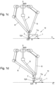
- the object point TCP is located in Fig. 1a in its starting position A, which is preferably arranged at rest in the base coordinate system BCS. Meanwhile, the transport unit 1 moves along the transport trajectory T1 in the reference coordinate system, ie here in the base coordinate system BCS.
- a transport unit coordinate system TF which is different from the reference coordinate system, is provided.
- a coupling process P1 whereby the object point TCP is moved along a coupling path z1 to a predetermined starting point S1 in the transport unit coordinate system TF.
- the starting point S1 thus moves together with the transport unit coordinate system TF along the transport trajectory T1.
- the starting point S1 can be, for example, the origin 0 of the transport unit coordinate system TF, as shown in the figures.
- the coupling path z1 advantageously starts at the starting position A in the reference coordinate system (here the base coordinate system BCS) and is preferably planned in the transport unit coordinate system TF.
- the object point TCP thus starts at the starting position A ( Fig. 1a ), follows the coupling path z1 ( Fig. 1b ) and finally arrives at the starting point S1 in the transport unit coordinate system TF ( Fig. 1c ) at.
- the coupling path z1 (and thus also the starting position A) can be moved with the transport unit 1 and thus with the transport unit coordinate system TF.
- the position/speed/acceleration of the object point TCP can also be taken into account in order to ensure a continuous transition of the object point TCP to the coupling path z1.
- At least one section of the coupling path z1 can be calculated based on the position and/or the speed and/or the acceleration of the transport unit 1.
- the coupling path z1 can also be adapted, preferably continuously, to the current position and/or speed and/or acceleration. This ensures that the movement of the transport unit 1 (and thus of the starting point S1 in the transport unit coordinate system TK, here the origin 0 of the transport unit coordinate system TF) along the transport trajectory T1 is taken into account and that the coupling path z1 actually ends at the starting point S1.
- the coupling path z1 leading to the coupling coordinates S1 runs continuously, preferably continuously up to the first, second or higher derivative, to the planned object path z TF .
- Continuous up to the first derivative means a continuous speed
- continuous up to the second derivative means a continuous acceleration (ie an acceleration without a jump).
- the coupling coordinates S1 can be used to directly enter the object trajectory z TF .
- Fig. 1a the object point TCP in its starting position A, whereupon the coupling process P1 is started.
- the object point TCP is already on the coupling path z1 and in Fig. 1c already at the end of the coupling path z1 at the starting point S1.
- the transport unit 1 and thus also the transport unit coordinate system TF compared to Fig. 1a has already moved further along the transport trajectory T1.
- the position of the transport unit 1 and the transport unit coordinate system TF from Fig. 1a dashed in Fig. 1b shown.
- Fig. 1c the object point TCP has reached the coupling coordinate S1 in the transport unit coordinate system TF, ie here the origin 0 of the transport unit coordinate system TF (in Fig. 1c Transport unit 1 has moved towards Fig. 1b along the transport trajectory T1).
- the coupling process P1 is thus completed and the synchronous phase P2 can be started.
- the object point TCP follows, as in Fig. 1d shown, in the synchronous phase P2 of the object path z TF , wherein the object path z TF is specified in relation to the transport unit coordinate system TF. Since the transport unit coordinate system TF is moved with the transport unit 1 along the transport trajectory T1, according to the invention at least one section of the object path z TF is transferred from the transport unit coordinate system TF to the base coordinate system BCS. This means that at least one respective section of the movement sequence of the object point TCP is always known in relation to the base coordinate system BCS, with which the object 2 can be actuated accordingly.
- a decoupling process P3 can be provided, during which a decoupling path z3 is provided for the object point TCP, as shown in Fig. 3a, 3b and 3c is shown as an example.
- the decoupling path z3 starts on the object path z TF , preferably on a given decoupling point, e.g. at the origin, and preferably ends at an end position E in the base coordinate system BCS. It is advantageous if a continuous transition from the object path z TF to the decoupling path z3 is specified. The transition can run continuously up to the first, second or higher derivative.
- the object point TCP is located in Fig. 3a at the origin 0 as decoupling point and in Fig. 3b on the decoupling track z3 and in Fig. 3c at the end of the decoupling path z3 at the end position E.
- the end point E can correspond to the starting point A.
- the decoupling path z3 is advantageously calculated in the base coordinate system BCS, in which the end position E is also located.
- the entire object path z TF can be transferred from the transport unit coordinate system TF to the basic coordinate system BCS.
- path points or path sections are transformed in each case, which allows for time-optimized control of the movement of object 2.
- the current positioning of the object point TCP on the object path z TF can be considered to be dependent on a path progress parameter s.
- the path progress parameter s can, as a scalar parameter, describe the progress of the object point TCP on the object path z TF .
- the transfer to the base coordinate system BCS can thus be carried out by transferring the object path z TF and/or derivatives according to the path progression parameter s and/or time, preferably point by point or section by section, into a machine coordinate system MCS. This can be done using a time-dependent transformation rule T MCS ⁇ TF (t).
- the section of the object path z MCS transferred to the machine coordinate system MCS can in turn be transferred, preferably point by point or section by section, from the machine coordinate system MCS to the base coordinate system BCS.
- This can be done using a transformation rule T BCS ⁇ MCS (s) that is dependent on the path progress parameter s, especially if it was previously transformed into the machine coordinate system MCS using a time-dependent transformation rule T MCS ⁇ TF (t).
- the transformation from the machine coordinate system MCS to the base coordinate system BCS can also be carried out by means of a time-dependent transformation rule T BCS ⁇ MCS (t) or by means of a transformation rule T BCS ⁇ MCS (s,t) that depends on the time and the path progression parameter s.
- the transport trajectory T1 can be assumed to be known for the time horizon for which the transfer to the base coordinate system BCS takes place.
- the machine coordinate system MCS can also correspond to a fixed global coordinate system. As mentioned, a direct transformation to the base coordinate system BCS can of course also take place without first transforming to the machine coordinate system MCS.
- the time-dependent transformation rule T MCS ⁇ TF (t) or T BCS ⁇ MCS (t) includes the time-dependent movement of the transport unit coordinate system TF with the transport unit 1 along the transport trajectory T1.
- T MCS ⁇ TF (t) and T BCS ⁇ MCS (s) or T MCS ⁇ TF (s) and T BCS ⁇ MCS (t) which depend on the orbital progression parameter s result in new partial derivatives with respect to the orbital progression parameter s ⁇ z BCS s t ⁇ s and with respect to time t ⁇ z BCS s t ⁇ t - from the second derivative onwards, mixed terms also arise.
- the object point TCP can be moved along the object path z TF using a number of axes R connected to the object 2.
- Kinematic axis states e.g. axis angles and/or derivatives thereof, can be used for the axes R.
- the kinematic axis states can be specified in relation to a Cartesian coordinate system, e.g. an axis coordinate system ACS.
- the partial derivatives of the object path ⁇ z BCS s t ⁇ s , ... , ⁇ z BCS s t ⁇ t , ... be converted into the axis coordinate system ACS using inverse kinematics: ( ⁇ q ACS s t ⁇ s , ⁇ q ACS s t ⁇ t , ... ).
- This also makes it possible to calculate a time derivative of the path progression parameter s(t) such that at least one kinematic axis state of an axis R lies within axis limit values.
- the speed of the advancing object point TCP along the object path z TF can be represented by the time course of the path progression parameter s(t).
- a speed q ⁇ ACS of an axis R can be provided as a kinematic axis state, with a maximum speed q ⁇ ACS ,max and/or a minimum speed q ⁇ ACS, min being provided as an axis limit value.
- the time derivative of the path progress parameter s can be determined to determine how quickly the path progress parameter s can change without the axis limits being exceeded by the axis states.
- a kinematic axis state of an axis R is always at an axis limit value q ⁇ ACS ,max , q ⁇ ACS ,min in order to obtain an optimal movement of the object point TCP along the object path z TF (eg in relation to time).
- the factor can, for example, represent a minimum time, whereby the movement is time-optimal. If the factor represents a minimum energy, the movement is minimal in relation to the energy occurring.
- the path progress parameter s(t) can be evaluated for the current time t, for example, and the position z TF (t) on the object path z TF determined in this way can be transferred to the base coordinate system BCS, from which the axis angles can be determined using inverse kinematics. If the movement of the transport unit coordinate system TF used for planning along the transport trajectory T1 deviates from the actual movement, the axis limit values may be exceeded.
Landscapes
- Engineering & Computer Science (AREA)
- Manufacturing & Machinery (AREA)
- Physics & Mathematics (AREA)
- General Physics & Mathematics (AREA)
- Automation & Control Theory (AREA)
- Human Computer Interaction (AREA)
- General Engineering & Computer Science (AREA)
- Quality & Reliability (AREA)
- Manipulator (AREA)
- Numerical Control (AREA)
Description
- Die gegenständliche Erfindung betrifft ein Verfahren zum Steuern einer Bewegung eines Objekts in Relation zu einer Transporteinheit eines Transportsystems, wobei die Transporteinheit in Bezug auf ein Bezugskoordinatensystem entlang einer vorgegeben Transporttrajektorie bewegt wird. Weiters betrifft die gegenständliche Erfindung ein System aus einem Transportsystem mit einer entlang einer in Bezug auf ein Bezugskoordinatensystem vorgegeben Transporttrajektorie bewegten Transporteinheit und einem in Relation zur Transporteinheit bewegten Objekt.
- In Transportsystemen wird eine Transporteinheit entlang einer Transporttrajektorie bewegt, wobei die Transporttrajektorie beispielsweise in Bezug auf ein Bezugskoordinatensystem betrachtet werden kann. So können beispielsweise elektromagnetische Transportsysteme, wie Langstatorlinearmotoren oder Planarmotoren vorgesehen sein. Bei einem Langstatorlinearmotor ist eine Transportstrecke vorgesehen, entlang welcher zumindest ein Teil der Transporttrajektorie verläuft; bei einem Planarmotor verläuft zumindest ein Teil der Transporttrajektorie in einer Transportebene. Es kann weiter erforderlich sein, dass ein Objekt an der Transporteinheit entlang einer Objektbahn bewegt wird. Da die Transporteinheit selbst eine Bewegung durchführt, muss bei der Steuerung der Objektbahn auch die Transporttrajektorie berücksichtigt werden. Entsprechend schlägt die
US 10,261,491 B1 - Weiterhin ist aus der
US 5,727,132 ein Verfahren zur Steuerung eines Roboters zum Verfolgen eines Objekts mit Hilfe eines optischen Sensors bekannt, wobei der Roboter vorgegebene Operationen an einem von einer Fördereinrichtung bewegten Werkstück durchführen soll. Erreicht das Werkstück eine gelernte Tracking-Startposition, wird vom Roboter ein Operationsprogramm ausgeführt, um Tracking-Bewegungen in Bezug auf ein Tracking-Koordinatensystem auszuführen. Dabei wird der Roboter auf einer Trajektorie zu einem berechneten bzw. korrigierten Zielpunkt bewegt, um das Werkstück zu erreichen. - Auch aus der
DE 101 62 967 A1 ist ein Verfahren zur Steuerung eines Roboters und eine zugehörige Steuerung bekannt, wobei der Roboter einem auf einem Fördermittel bewegten Gegenstand folgt, um am Gegenstand vorbestimmte Handlungen durchzuführen. Der Gegenstand wird dazu mit einer Kamera erfasst, welche mit der Robotersteuerung verbunden ist, und eine aktuelle Position des Gegenstands im Fördermittelkoordinatensystem ermittelt und aktualisiert. Der Weg des Roboters, um dem Gegenstand zu folgen, wird dann durch Transformieren der Position des Werkstücks vom Förderkoordinatensystem in ein Roboterkoordinatensystem gebildet. - Es ist eine Aufgabe der gegenständlichen Erfindung, eine verbesserte Steuerung und Planung einer Objektbahn entlang einer Transporttrajektorie zu ermöglichen.
- Diese Aufgabe wird gelöst, indem eine synchrone Phase vorgesehen wird, wobei während der synchronen Phase eine Bewegung eines Objektpunkts des Objekts entlang einer Objektbahn in Bezug auf ein Transporteinheitenkoordinatensystem, ungleich dem Bezugskoordinatensystem, vorgegeben wird, wobei das Transporteinheitenkoordinatensystem mit der Transporteinheit entlang der Transporttrajektorie bewegt wird. Dabei wird die Transporttrajektorie zumindest abschnittsweise unter Verwendung der Position und/oder der Geschwindigkeit und/oder der Beschleunigung der Transporteinheit ermittelt und zumindest ein Bahnpunkt der Objektbahn wird vom Transporteinheitenkoordinatensystem in ein Basiskoordinatensystem transformiert, um die Bewegung des Objektpunkts entlang der Objektbahn in Bezug auf das Basiskoordinatensystem zu steuern.
- Weiters wird die Aufgabe durch eine Steuereinheit gelöst, welche ausgestaltet ist, während einer synchronen Phase eine Bewegung eines Objektpunkts des Objekts entlang einer Objektbahn in Bezug auf ein vom Bezugskoordinatensystem verschiedenes Transporteinheitenkoordinatensystem, welches mit der Transporteinheit entlang der Transporttrajektorie bewegt wird, vorzugeben, wobei die Transporttrajektorie unter Verwendung der Position und/oder der Geschwindigkeit und/oder der Beschleunigung der Transporteinheit zumindest abschnittsweise ermittelbar ist, und zumindest einen Bahnpunkt der Objektbahn, vom Transporteinheitenkoordinatensystem in ein Basiskoordinatensystem zu transformieren, um die Bewegung des Objekts in Bezug auf das Basiskoordinatensystem zu steuern.
- Sind mehrere Objekte vorgesehen, so können die Objekte jeweils ein eigenes Transporteinheitenkoordinatensystem aufweisen. Die Objektbahn kann als geometrisches Konstrukt angesehen werden, entlang welchem der Objektpunkt relativ zur Transporteinheit bewegt wird. Da die Objektbahn in Bezug auf ein Transporteinheitenkoordinatensystem definiert ist, welches entlang der Transporttrajektorie (welche in Bezug auf ein Bezugskoordinatensystem definiert ist) mitbewegt wird, hat die Objektbahn eine einfachere Form/Geometrie/Gestalt, als wenn sie direkt in Bezug auf das Bezugskoordinatensystem definiert wäre.
- Vorzugsweise ist das Transportsystem ein Langstatorlinearmotor, ein Planarmotor oder ein Stetigfördersystem (z.B. ein Förderbandsystem), wobei das Objekt vorteilhafterweise Teil einer Kinematik, z.B. ein Teil eines Werkzeugs, ist. Der Objektpunkt kann beispielsweise eine Werkzeugspitze darstellen.
- Vorzugsweise entspricht das Bezugskoordinatensystem dem Basiskoordinatensystem. Damit wird die Transporttrajektorie in Bezug auf das Basiskoordinatensystem angegeben.
- Die Transporttrajektorie wird vorzugsweise vom Transportsystem vorgegeben und kann somit nicht von der Steuereinheit beeinflusst werden.
- Die Objektbahn kann vorab in Bezug auf das Transporteinheitenkoordinatensystem festgelegt werden oder während der Bewegung in Bezug auf das Transporteinheitenkoordinatensystem ermittelt werden. Die Objektbahn kann beispielsweise durch eine Eingabe eines Benutzers, z.B. durch setzen von Variablen etc. festgelegt oder beeinflusst werden.
- Vorzugsweise wird ein Fortschritt des Objektpunkts entlang der Objektbahn über einen Bahnfortschrittsparameter angegeben, wobei die Objektbahn und/oder Ableitungen der Objektbahn entlang des Bahnfortschrittsparameters, vorzugsweise punktweise, unter Verwendung einer ersten Transformationsvorschrift vom Transporteinheitenkoordinatensystem in ein Maschinenkoordinatensystem überführt wird und die in das Maschinenkoordinatensystem überführte Objektbahn unter Verwendung einer zweiten Transformationsvorschrift in das Basiskoordinatensystem transformiert wird.
- Der Bahnfortschrittsparameter kann eine eindimensionale Größe darstellen, welche den Fortschritt des Objektpunkts auf der Bahn repräsentiert. Der Bahnfortschrittsparameter kann somit die Position und Orientierung des Objektpunkts angegeben.
- Statt dem Bahnfortschrittsparameter kann auch direkt die Position auf der Objektbahn oder eine andere Darstellung des Bahnfortschritts des Objektpunkts auf der Objektbahn gewählt werden.
- Vorzugsweise ist die erste Transformationsvorschrift zeitabhängig. Weiters kann die zweite Transformationsvorschrift vom Bahnfortschrittsparameter abhängig und/oder zeitabhängig sein.
- Es kann vor der synchronen Phase ein Kopplungsvorgang vorgesehen sein, wobei während dem Kopplungsvorgang das Objekt entlang einer Kopplungsbahn auf einen vorgegebenen Startpunkt im Transporteinheitenkoordinatensystem bewegt wird.
- Es ist besonders vorteilhaft, wenn die Kopplungsbahn stetig an die Objektbahn anschließt, vorzugsweise stetig bis zur zweiten Ableitung. Damit wird für das Objekt ein stetiger Übergang von der Kopplungsbahn auf die Objektbahn erreicht, womit beispielsweise ein Stopp, ein Geschwindigkeitsssprung oder ein Beschleunigungssprung des Objekts vermieden wird.
- Die Kopplungsbahn startet vorzugsweise an einer festen Ruheposition im Basiskoordinatensystem. Das Objekt befindet sich vorzugsweise in der Ruheposition, wenn es sich außerhalb der synchronen Phase, sowie - sofern ein Kopplungsvorgang vorgesehen ist - außerhalb des Kopplungsvorgangs und - sofern ein Entkopplungsvorgang vorgesehen ist - außerhalb des Entkopplungsvorgangs befindet. Der Objektpunkt kann aber auch aus einer Bewegung in die Kopplungsbahn überführt werden. Die Kopplungsbahn kann im Transporteinheitenkoordinatensystem geplant und kann in Folge bedarfsweise optimiert werden.
- Die Kopplungsbahn kann unter Verwendung der Position und/oder der Geschwindigkeit und/oder der Beschleunigung der Transporteinheit, ermittelt, vorzugsweise über ein Modell extrapoliert, werden. Beispielsweise können Bahnpunkte oder Bahnabschnitte der Kopplungsbahn kontinuierlich ermittelt werden. Die ermittelten Bahnpunkte oder Bahnabschnitte der Kopplungsbahn können an die Bewegung des Objektkoordinatensystems angepasst werden, um sicherzustellen, dass die Kopplungsbahn im Startpunkt mündet. Auch kann bei der Ermittlung der Kopplungsbahn die aktuelle Bewegung des Objektpunkts berücksichtigt werden.
- Das Objekt kann unter Verwendung einer Anzahl an Achsen entlang der Objektbahn bewegt werden, wobei aus dem in das Basiskoordinatensystem transformierten zumindest einen Bahnpunkt der Objektbahn mittels einer Inverskinematik kinematische und/oder dynamische Achszustände, vorzugsweise Achswinkel und/oder deren zeitliche und/oder räumliche Ableitungen, der Anzahl Achsen ermittelt werden können.
- Als Basiskoordinatensystem kann ein festes globales Koordinatensystem vorgesehen sein. Das Basiskoordinatensystem kann aber auch bewegt sein, insbesondere wenn es an einer Achse angeordnet ist und diese Achse nicht Teil der zugehörigen Kinematik oder der Bewegungssteuerung der zugehörigen Kinematik ist.
- Die Achszustände können weiters mit Achsgrenzwerten verglichen werden. Damit kann sichergestellt werden, dass die Achszustände die Achsgrenzwerte nicht verletzten und die Änderung der Achszustände wird so bestimmt, dass zumindest ein Achszustand einer Achse sich stets an einem Achsgrenzwert befindet, um eine zeitoptimale Bewegung des Objekts entlang der Objektbahn zu erhalten.
- Die Achsgrenzwerte können kinematischer Natur sein (Geschwindigkeitsgrenzwert, Beschleunigungsgrenzwert, Ruckgrenzwert etc.). Andererseits können die Achsgrenzwerte auch dynamischer Natur sein (Kraftgrenzwert, Momentgrenzwert etc.) sein Es kann nach der synchronen Phase ein Entkopplungsvorgang vorgesehen sein, wobei während dem Entkopplungsvorgang der Objektpunkt entlang einer Entkopplungsbahn von der Objektbahn entfernt wird.
- Die Entkopplungsbahn kann auf einem vorgegebenen Endpunkt im Basiskoordinatensystem enden.
- Vorteilhafterweise schließt die Entkopplungsbahn stetig, vorzugsweise stetig bis zur zweiten Ableitung, an die Objektbahn an. Damit wird für das Objekt ein stetiger Übergang von der Objektbahn auf die Kopplungsbahn erreicht, womit beispielsweise ein Stopp, ein Geschwindigkeitsssprung oder ein Beschleunigungssprung des Objekts vermieden wird.
- Nach der synchronen Phase kann ein Übergangsvorgang eine weitere synchrone Phase vorgesehen sein, wobei während des Übergangsvorgangs der Objektpunkt entlang einer Übergangstrajektorie von der Objektbahn auf einen weiteren Startpunkt in einem weiteren Transporteinheitenkoordinatensystem bewegt wird.
- Bei der Steuerung der Bewegung des Objektpunkts (TCP) kann sichergestellt werden, dass die Geschwindigkeit des Objektpunkts (TCP) vorgegebene kinematische und/oder dynamische Limits nicht überschreitet, wobei es besonders vorteilhaft ist, wenn die Steuerung der Bewegung des Objektpunkts (TCP) möglichst am kinematischen und/oder dynamischen Limit erfolgt.
- Die gegenständliche Erfindung wird nachfolgend unter Bezugnahme auf die
Figuren 1 bis 3c näher erläutert, die beispielhaft, schematisch und nicht einschränkend vorteilhafte Ausgestaltungen der Erfindung zeigen. Dabei zeigt -
Fig.1a ein Objektpunkt eines Objekts in einer Anfangsposition, -
Fig.1b der Objektpunkt des Objekts auf der Koppeltrajektorie, -
Fig.1c der Objektpunkt auf einem Startpunkt der Objektbahn im Transporteinheitenkoordinatensystem, -
Fig.1d der Objektpunkt auf der Objektbahn im Transporteinheitenkoordinatensystem, -
Fig.2a eine Transformation vom Transporteinheitenkoordinatensystem über ein Maschinenkoordinatensystem in das Basiskoordinatensystem, -
Fig.2b die zeitliche und örtliche partielle Ableitung der in das Basiskoordinatensystem transformierten Objektbahn, -
Fig.3a der Objektpunkt am Beginn der Entkopplungsbahn, -
Fig.3b der Objektpunkt auf der Entkopplungsbahn -
Fig.3c der Objektpunkt auf der Endposition am Ende der Entkopplungsbahn. - In den Figuren ist jeweils ein Basiskoordinatensystem BCS festgelegt. Es ist eine Transporteinheit 1 eines Transportsystems 10 vorgesehen, welche entlang einer Transporttrajektorie T1 bewegt wird. Die Transporttrajektorie T1 verläuft nur beispielhaft horizontal. Es kann ein elektromagnetisches Transportsystem, z.B. ein Planarmotor oder ein Langstatorlinearmotor, als Transportsystem 10 vorgesehen sein. Bei einem Planarmotor ist eine Transportebene vorgesehen, in welcher die Transporttrajektorie T1 verläuft. Bei einem Langstatorlinearmotor ist eine Transportstrecke vorgesehen, entlang welcher eine Transporttrajektorie T1 verläuft. Es wird in elektromagnetischen Transportsystemen durch eine Bestromung von Antriebsspulen (an der Transporteinheit oder an der Transportstrecke/in der Transportebene) ein Magnetfeld erzeugt, welches durch ein Zusammenwirken mit Antriebsmagneten eine Vortriebskraft erzeugt und somit die Bewegung der Transporteinheit 1 verursacht. Sind die Antriebsspulen an der Transporteinheit 1 vorgesehen, so befinden sich die Antriebsmagnete an der Transportstrecke / in der Transportebene. Sind die Antriebsspulen an der Transportstrecke / in der Transportebene vorgesehen, so befinden sich die Antriebsmagnete an der Transporteinheit 1. Weiters kann das Transportsystem als Stetigfördersystem (z.B. als Förderbandsystem) ausgestaltet sein. Dabei stellt die Transporteinheit die gegenüber der Transportstrecke bewegliche Einheit oder einen Teil davon dar, also bei einem Förderbandsystem beispielsweise das Förderband selbst oder einen Bandabschnitt des Förderbands. Die Transporttrajektorie T1 ist in Bezug auf ein Bezugskoordinatensystem festgelegt, d.h. im dargestellten Ausführungsbeispiel in Bezug auf das Basiskoordinatensystem BCS. Transportsysteme 10, insbesondere Langstatorlinearmotoren und Planarmotoren sind grundlegend bekannt, weshalb diese an dieser Stelle nicht näher beschrieben werden. In den Figuren wird lediglich ein Ausschnitt eines Transportsystems 10 dargestellt, wobei ein Abschnitt der Transporttrajektorie T1 und eine zugehörige Transporteinheit 1 zu sehen ist.
- Es ist weiters ein Objekt 2 vorgesehen, wobei ein Objektpunkt TCP des Objekts 2 entlang einer Objektbahn zTF bewegt werden soll. Der Objektpunkt TCP des Objekts 2 kann frei am Objekt 2 festgelegt werden. Als Objekt 2 kann beispielsweise ein Teil, z.B. ein Werkzeug, einer, z.B. seriellen, Kinematik vorgesehen sein, wobei beispielsweise eine Werkzeugspitze als Objektpunkt TCP festgelegt werden kann.
- Nach dem Stand der Technik erfolgt die Steuerung der Bewegung des Objektpunkts TCP durch Planung der Objektbahn zTF direkt in Bezug auf jenes Koordinatensystem, in welcher die Transporttrajektorie festgelegt ist, d.h. im dargestellten Ausführungsbeispiel in Bezug auf das Basiskoordinatensystem BCS. Dies ist jedoch nur möglich, wenn die Transporttrajektorie T1 und die Objektbahn zTF vorab bekannt sind und die Objektbahn zTF die Transporttrajektorie T1 beeinflussen kann.
- Erfindungsgemäß wird hingegen die Objektbahn zTF in Bezug auf ein Transporteinheitenkoordinatensystem TF festgelegt, wobei das Transporteinheitenkoordinatensystem TF nicht dem Bezugskoordinatensystem entspricht, d.h. sich vom Bezugskoordinatensystem unterscheidet. In der dargestellten Ausführungsform entspricht das Bezugskoordinatensystem dem Basiskoordinatensystem BCS, woraus folgt, dass das Transporteinheitenkoordinatensystem TF nicht dem Basiskoordinatensystem BCS entspricht. Die Objektbahn zTF beschreibt grundlegend die Bahn, entlang welcher sich der Objektpunkt TCP in Bezug auf das Transporteinheitenkoordinatensystem TF bewegt. Da sich das Transporteinheitenkoordinatensystem TF mit der Transporteinheit 1 mit bewegt, wird die Objektbahn zTF mit der Transporteinheit 1 mit bewegt. Es wird zumindest ein Bahnpunkt der Objektbahn zTF vom Transporteinheitenkoordinatensystem TF in das erste Koordinatensystem (hier das Basiskoordinatensystem BCS) transformiert.
- Sind mehrere Transporteinheiten 1 vorgesehen, so können die Transporteinheiten 1 jeweils ein eigenes Transporteinheitenkoordinatensystem TF aufweisen. Somit kann jeweils in Bezug auf die Transporteinheiten 1 jeweils eine synchrone Phase P2 vorgesehen sein, während welcher eine Bewegung des Objektpunkts TCP entlang einer Objektbahn zTF in Bezug auf das der Transporteinheit 1 zugehörigen Transporteinheitenkoordinatensystems TF, ungleich dem Bezugskoordinatensystem, vorgegeben wird, wobei das Transporteinheitenkoordinatensystem TF mit der Transporteinheit 1 entlang der Transporttrajektorie T1 bewegt wird und wobei zumindest ein Bahnpunkt der Objektbahn zTF vom Transporteinheitenkoordinatensystem TF in ein Basiskoordinatensystem BCS überführt wird, um die Bewegung des Objektpunkts TCP entlang der Objektbahn zTF in Bezug auf das Basiskoordinatensystem BCS zu steuern. Vorzugsweise sind die synchronen Phasen P2 der sequentiell vorgesehen, womit die Bewegung des Objektpunkts TCP entlang der jeweiligen Objektbahnen zTF sequentiell erfolgt. Der Übergang von einer synchronen Phase P2 in die nächste synchrone Phase P2 kann über einen Entkopplungsvorgang P3 aus der einen synchronen Phase und einen darauffolgenden Kopplungsvorgang P1 in die nächste synchrone Phase P2 erfolgen.
- Es kann vorgesehen sein, dass das Transporteinheitenkoordinatensystem TF fest vorgegeben und nicht beeinflussbar ist, beispielsweise, indem eine externe Transporteinrichtung 1 vorgesehen ist.
- Die Transporttrajektorie T1 kann vorab bekannt oder unbekannt sein. Ist die Transporttrajektorie T1 unbekannt, so kann sie auch unter Verwendung der Position und/oder der Geschwindigkeit und/oder der Beschleunigung der Transporteinheit 1 ermittelt, vorzugsweise über ein Modell extrapoliert, werden.
- Es kann beispielhafterweise eine Raute als Objektbahn zTF vorgesehen sein. Es sind jedoch beliebige eindimensionale, zweidimensionale (oder in einem mehrdimensionalen Transporteinheitenkoordinatensystem TF auch mehrdimensionale) Objektbahnen zTF möglich, z.B. Kreise, Quader, Schraubenlinien etc. Die Objektbahn zTF kann in Bezug auf das Transporteinheitenkoordinatensystem TF fest vorgegeben werden oder auch während der synchronen Phase P2 oder eines Kopplungsvorgangs P1 ermittelt werden. Zudem kann die Objektbahn zTF in sich geschlossen sein, einen oder mehrere Umläufe (oder eine Fraktion von ganzzahligen Umläufen) aufweisen etc.
- Das Basiskoordinatensystem BCS und/oder Transporteinheitenkoordinatensystem TF und/oder Bezugskoordinatensystem (welches hier dem Basiskoordinatensystem BCS entspricht) sind nur zur einfacheren Darstellung zweidimensional festgelegt und können beispielsweise auch ein dreidimensionales, mehrdimensionales kartesisches oder nicht-kartesisches Koordinatensystem darstellen. Auch können Basiskoordinatensystem BCS und/oder Transporteinheitenkoordinatensystem TF und Bezugskoordinatensystem z.B. ein mehrdimensionales (z.B. ein 6-dimensionales) nicht-kartesisches Koordinatensystem darstellen.
- Der Objektpunkt TCP befindet sich in
Fig. 1a in seiner Startposition A, welche vorzugsweise ruhend im Basiskoordinatensystem BCS angeordnet ist. Währenddessen bewegt sich die Transporteinheit 1 entlang der Transporttrajektorie T1 im Bezugskoordinatensystem, d.h. hier im Basiskoordinatensystem BCS. Für den Objektpunkt TCP ist ein, vom Bezugskoordinatensystem verschiedenes, Transporteinheitenkoordinatensystem TF vorgesehen. - Es folgt ausgehend von
Fig. 1a ein Kopplungsvorgang P1, wobei der Objektpunkt TCP entlang einer Kopplungsbahn z1 auf einen vorgegebenen Startpunkt S1 im Transporteinheitenkoordinatensystem TF bewegt wird. Der Startpunkt S1 bewegt sich somit gemeinsam mit dem Transporteinheitenkoordinatensystem TF entlang der Transporttrajektorie T1. Als Startpunkt S1 kann beispielsweise der Ursprung 0 des Transporteinheitenkoordinatensystem TF vorgesehen sein, wie es in den Figuren dargestellt ist. Die Kopplungsbahn z1 startet vorteilhafterweise an der Startposition A im Bezugskoordinatensystem (hier Basiskoordinatensystem BCS) und wird vorzugsweise im Transporteinheitenkoordinatensystem TF geplant. Damit startet der Objektpunkt TCP an der Startposition A (Fig 1a ), folgt der Kopplungsbahn z1 (Fig. 1b ) und kommt schlussendlich am Startpunkt S1 im Transporteinheitenkoordinatensystem TF (Fig. 1c ) an. - Da die Transporteinheit 1 entlang der Transporttrajektorie T1 in Bezug auf das Bezugskoordinatensystem (hier das Basiskoordinatensystem BCS) eine Bewegung durchführt, kann die Kopplungsbahn z1 (und damit auch die Startposition A) mit der Transporteinheit 1 und somit mit dem Transporteinheitenkoordinatensystem TF mitbewegt werden. Bei der Berechnung der Kopplungsbahn z1 kann auch die Position/Geschwindigkeit/Beschleunigung des Objektpunkts TCP mitberücksichtigt werden, um einen stetigen Übergang des Objektpunkts TCP auf die Kopplungsbahn z1 sicherzustellen.
- Weiters kann zumindest ein Abschnitt der Kopplungsbahn z1 anhand der Position und/oder der Geschwindigkeit und/oder der Beschleunigung der Transporteinheit 1 berechnet werden. Auch kann die Kopplungsbahn z1, vorzugsweise kontinuierlich, an die aktuelle Position und/oder Geschwindigkeit und/oder Beschleunigung angepasst werden. Damit kann sichergestellt werden, dass die Bewegung der Transporteinheit 1 (und damit des Startpunkts S1 im Transporteinheitenkoordinatensystem TK, hier der Ursprung 0 des Transporteinheitenkoordinatensystems TF) entlang der Transporttrajektorie T1 berücksichtigt wird und die Kopplungsbahn z1 auch tatsächlich im Startpunkt S1 mündet.
- Liegt der Startpunkt S1, wie in den
Figuren 1d dargestellt, auf der geplanten Objektbahn zTF, so ist es vorteilhaft, wenn die in den Koppelkoordinaten S1 mündende Kopplungsbahn z1 stetig, vorzugsweise stetig bis zur ersten, zweiten oder höheren Ableitung, zur geplanten Objektbahn zTF verläuft. Stetig bis zur ersten Ableitung bedeutet eine stetige Geschwindigkeit, stetig bis zur zweiten Ableitung bedeutet eine stetige Beschleunigung (d.h. eine Beschleunigung ohne Sprung). Sobald der Objektpunkt TCP die Kopplungsbahn z1 durchlaufen hat, kann über die Koppelkoordinaten S1 direkt in die Objektbahn zTF übergegangen werden. - Wie erwähnt zeigt
Fig. 1a den Objektpunkt TCP in seiner Startposition A, woraufhin der Kopplungsvorgang P1 gestartet wird. InFig. 1b befindet sich der Objektpunkt TCP bereits auf der Kopplungsbahn z1 und inFig. 1c bereits am Ende der Kopplungsbahn z1 im Startpunkt S1. Es ist zu beachten, dass sich inFig. 1b die Transporteinheit 1 und damit auch das Transporteinheitenkoordinatensystem TF gegenüberFig. 1a bereits weiter entlang der Transporttrajektorie T1 bewegt hat. Es ist zur deutlicheren Darstellung die Position der Transporteinheit 1 und des Transporteinheitenkoordinatensystems TF ausFig. 1a strichliert inFig. 1b dargestellt. - In
Fig. 1c hat der Objektpunkt TCP die Koppelkoordinate S1 im Transporteinheitenkoordinatensystem TF, d.h. hier den Ursprung 0 des Transporteinheitenkoordinatensystems TF, erreicht (inFig. 1c hat sich die Transporteinheit 1 gegenüberFig. 1b entlang der Transporttrajektorie T1 weiterbewegt). Damit ist der Kopplungsvorgang P1 abgeschlossen und es kann die synchrone Phase P2 gestartet werden. - Der Objektpunkt TCP folgt, wie in
Fig. 1d dargestellt, in der synchronen Phase P2 der Objektbahn zTF, wobei die Objektbahn zTF in Bezug auf das Transporteinheitenkoordinatensystem TF vorgegeben wird. Da das Transporteinheitenkoordinatensystem TF mit der Transporteinheit 1 entlang der Transporttrajektorie T1 bewegt wird, wird erfindungsgemäß zumindest ein Abschnitt der Objektbahn zTF vom Transporteinheitenkoordinatensystem TF in das Basiskoordinatensystem BCS überführt. Damit ist immer zumindest ein jeweiliger Abschnitt des Bewegungsablaufs des Objektpunkts TCP in Bezug auf das Basiskoordinatensystem BCS bekannt, womit das Objekt 2 entsprechend aktuiert werden kann. - Nach dem Ende einer synchronen Phase P2 kann ein Entkopplungsvorgang P3 vorgesehen sein, während welchem eine Entkopplungsbahn z3 für den Objektpunkt TCP vorgesehen ist, wie es in
Fig. 3a, 3b und3c beispielhaft dargestellt ist. Die Entkopplungsbahn z3 startet auf der Objektbahn zTF, vorzugsweise auf einem vorgegebenen Entkopplungspunkt, z.B. am Ursprung, und endet vorzugsweise an einer Endposition E im Basiskoordinatensystem BCS. Es ist vorteilhaft, wenn ein stetiger Übergang von der Objektbahn zTF in die Entkopplungsbahn z3 vorgegeben wird. Dabei kann der Übergang stetig bis zur ersten, zweiten oder höheren Ableitung verlaufen. Der Objektpunkt TCP befindet sich inFig. 3a im Ursprung 0 als Entkopplungspunkt und inFig. 3b auf der Entkopplungsbahn z3 und inFig. 3c am Ende der Entkopplungsbahn z3 an der Endposition E. - Sind ein Kopplungsvorgang P1 und ein Entkopplungsvorgang P3 vorgesehen, so kann der Endpunkt E dem Startpunkt A entsprechen. Die Entkopplungsbahn z3 wird vorteilhafterweise im Basiskoordinatensystem BCS, in welchem sich auch die Endposition E befindet, berechnet.
- Grundlegend kann die gesamte Objektbahn zTF vom Transporteinheitenkoordinatensystem TF in das Basiskoordinatensystem BCS überführt werden. Es ist jedoch vorteilhaft, wenn jeweils Bahnpunkte oder Bahnabschnitte transformiert werden, womit eine zeitoptimale Steuerung der Bewegung des Objekts 2 erfolgen kann. Die aktuelle Positionierung des Objektpunkts TCP auf der Objektbahn zTF kann als abhängig von einem Bahnfortschrittsparameter s betrachtet werden. Der Bahnfortschrittsparameter s kann als skalarer Parameter den Fortschritt des Objektpunkts TCP auf der Objektbahn zTF beschreiben.
- Die Überführung in das Basiskoordinatensystem BCS kann somit erfolgen, indem die Objektbahn zTF und/oder Ableitungen nach dem Bahnfortschrittsparameter s und/oder der Zeit vorzugsweise punktweise oder abschnittsweise, in ein Maschinenkoordinatensystem MCS überführt wird. Dies kann mittels einer zeitabhängigen Transformationsvorschrift TMCS←TF(t) erfolgen.
- Weiters kann der in das Maschinenkoordinatensystem MCS überführte Abschnitt der Objektbahn zMCS wiederum, vorzugsweise punktweise oder abschnittsweise, vom Maschinenkoordinatensystem MCS in das Basiskoordinatensystem BCS überführt werden. Dies kann, insbesondere wenn zuvor mittels einer zeitabhängigen Transformationsvorschrift TMCS←TF(t) in das Maschinenkoordinatensystem MCS transformiert wurde, mittels einer vom Bahnfortschrittsparameter s abhängigen Transformationsvorschrift TBCS←MCS(s) erfolgen.
- Die Transformation vom Maschinenkoordinatensystem MCS in das Basiskoordinatensystem BCS kann aber auch mittels einer zeitabhängigen Transformationsvorschrift TBCS←MCS(t) oder mittels einer von der Zeit und vom Bahnfortschrittsparameter s abhängigen Transformationsvorschrift TBCS←MCS(s,t) erfolgen.
- Die Transporttrajektorie T1 kann für den Zeithorizont, für welchen die Überführung in das Basiskoordinatensystem BCS erfolgt, als bekannt angenommen werden. Das Maschinenkoordinatensystem MCS kann auch einem festen globalen Koordinatensystem entsprechen. Wie erwähnt kann natürlich auch direkt eine Transformation in das Basiskoordinatensystem BCS erfolgen ohne zuvor in das Maschinenkoordinatensystem MCS zu transformieren.
- Die zeitabhängige Transformationsvorschrift TMCS←TF(t) oder TBCS←MCS(t) beinhaltet dabei die zeitabhängige Bewegung des Transporteinheitenkoordinatensystems TF mit der Transporteinheit 1 entlang der Transporttrajektorie T1.
- Durch die zeitabhängigen und vom Bahnfortschrittsparameter s abhängigen Transformationsvorschriften TMCS←TF(t) und TBCS←MCS(s) oder TMCS←TF(s) und TBCS←MCS(t) ergeben sich neue partielle Ableitungen bezüglich des Bahnfortschrittparameters s


- Der Objektpunkt TCP kann unter Verwendung einer Anzahl mit dem Objekt 2 verbundener Achsen R entlang der Objektbahn zTF bewegt werden. Für die Achsen R können kinematische Achszustände, z.B. Achswinkel und/oder Ableitungen davon, verwendet werden. Die kinematischen Achszustände können in Bezug auf ein kartesisches Koordinatensystem, z.B. ein Achskoordinatensystem ACS, vorgegeben sein. Somit können die partiellen Ableitungen der Objektbahn


- Damit ist es zudem möglich eine zeitliche Ableitung des Bahnfortschrittsparameters s(t) derart zu berechnen, dass zumindest ein kinematischer Achszustand einer Achse R innerhalb von Achsgrenzwerten liegt. Die Geschwindigkeit des fortschreitenden Objektpunkts TCP entlang der Objektbahn zTF kann über den zeitlichen Verlauf des Bahnfortschrittsparameters s(t) dargestellt werden.
- Beispielsweise kann eine Geschwindigkeit q̇ACS einer Achse R als kinematischer Achszustand vorgesehen sein, wobei eine maximale Geschwindigkeit q̇ ACS,max und/oder eine minimale Geschwindigkeit q̇ ACS,min als Achsgrenzwert vorgesehen sind. Somit wird sichergestellt, dass die Geschwindigkeit q̇ACS der Achse R die maximale Geschwindigkeit q̇ ACS,max nicht überschreitet und/oder oder die minimale Geschwindigkeit q̇ ACS,min nicht unterschreitet:


- Unter Verwendung dieser Zusammenhänge kann die zeitliche Ableitung des Bahnfortschrittsparameters s bestimmt werden, um zu bestimmen wie rasch sich der Bahnfortschrittsparameter s ändern kann, ohne dass die Achsgrenzwerte durch die Achszustände überschritten werden.
- Es kann auch vorgesehen sein, dass ein kinematischer Achszustand einer Achse R sich stets an einem Achsgrenzwert q̇ ACS,max, q̇ ACS,min befindet, um eine optimale Bewegung des Objektpunkts TCP entlang der Objektbahn zTF (z.B. in Bezug auf die Zeit) zu erhalten. Der Faktor kann beispielsweise eine minimale Zeit darstellen, womit die Bewegung zeitoptimal ist. Stellt der Faktor eine minimale Energie dar, so ist die Bewegung minimal in Bezug auf die auftretende Energie.
- Um sicherzustellen, dass der Objektpunkt TCP der Objektbahn zTF folgt, kann beispielsweise der Bahnfortschrittsparameter s(t) für die aktuelle Zeit t ausgewertet werden und die dadurch ermittelte Position zTF(t) auf der Objektbahn zTF in das Basiskoordinatensystem BCS überführt werden, woraus wiederum unter Verwendung der Inverskinematik die Achswinkel bestimmt werden können. Falls die zur Planung verwendete Bewegung des Transporteinheitenkoordinatensystems TF entlang der Transporttrajektorie T1 von der tatsächlichen Bewegung abweicht, werden die Achsgrenzwerte möglicherweise überschritten.
- Vorzugsweise wird in der synchronen Phase P2 und/oder während des Kopplungsvorgangs P1 und/oder während des Entkoppelvorgangs P3 sichergestellt, dass eine Geschwindigkeit und/oder eine Beschleunigung und/oder ein Ruck des Objektpunkts TCP entsprechende Achsgrenzwerte nicht verletzen.
Claims (22)
- Verfahren zum Steuern einer Bewegung eines Objekts (2) in Relation zu einer Transporteinheit (1) eines Transportsystems (10), wobei die Transporteinheit (1) in Bezug auf ein Bezugskoordinatensystem entlang einer vorgegeben Transporttrajektorie (T1) bewegt wird, dadurch gekennzeichnet, dass eine synchrone Phase vorgesehen wird, während der eine Bewegung eines Objektpunkts (TCP) des Objekts (2) entlang einer Objektbahn (zTF) in Bezug auf ein Transporteinheitenkoordinatensystem (TF), ungleich dem Bezugskoordinatensystem, vorgegeben wird, wobei das Transporteinheitenkoordinatensystem (TF) mit der Transporteinheit (1) entlang der Transporttrajektorie (T1) bewegt wird, dass die Transporttrajektorie (T1) zumindest abschnittsweise unter Verwendung der Position und/oder der Geschwindigkeit und/oder der Beschleunigung der Transporteinheit (1) ermittelt wird, und dass zumindest ein Bahnpunkt der Objektbahn (zTF) vom Transporteinheitenkoordinatensystem (TF) in ein Basiskoordinatensystem (BCS) transformiert wird, um die Bewegung des Objektpunkts (TCP) entlang der Objektbahn (zTF) in Bezug auf das Basiskoordinatensystem (BCS) zu steuern.
- Verfahren nach Anspruch 1, dadurch gekennzeichnet, dass das Bezugskoordinatensystem dem Basiskoordinatensystem (BCS) entspricht und/oder als Basiskoordinatensystem (BCS) ein festes globales Koordinatensystem verwendet wird.
- Verfahren nach Anspruch 1 oder 2, dadurch gekennzeichnet, dass die Transporttrajektorie (T1) vom Transportsystem (1) vorgegeben wird.
- Verfahren nach einem der Ansprüche 1 bis 3, dadurch gekennzeichnet, dass die Objektbahn (zTF) in Bezug auf das Transporteinheitenkoordinatensystem (TF) vorab festgelegt wird.
- Verfahren nach einem der Ansprüche 1 bis 4, dadurch gekennzeichnet, dass ein Fortschritt des Objektpunkts (TCP) entlang der Objektbahn (zTF) als Bahnfortschrittsparameter (s) angegeben wird, dass die Objektbahn (zTF) und/oder Ableitungen der parametrierten Objektbahn (zTF) entlang des Bahnfortschrittsparameters (s), zumindest abschnittsweise, vorzugsweise punktweise, unter Verwendung einer ersten Transformationsvorschrift vom Transporteinheitenkoordinatensystem (TF) in ein Maschinenkoordinatensystem (MCS) überführt wird, und dass die in das Maschinenkoordinatensystem (MCS) überführte Objektbahn (zMCS) unter Verwendung einer zweiten Transformationsvorschrift in das Basiskoordinatensystem (BCS) überführt wird.
- Verfahren nach Anspruch 5, dadurch gekennzeichnet, dass, die erste Transformationsvorschrift (TMCS←TF(t)) zeitabhängig ist und/oder die zweite Transformationsvorschrift (TBCS←MCS(s)) vom Bahnfortschrittsparameter (s) abhängig ist.
- Verfahren nach Anspruch 5 oder 6, dadurch gekennzeichnet, dass, die zweite Transformationsvorschrift (TBCS←MCS(t)) zeitabhängig ist.
- Verfahren nach Anspruch 5, dadurch gekennzeichnet, dass die erste Transformationsvorschrift (TMCS←TF(s)) vom Bahnfortschrittsparameter (s) abhängig ist, und dass die zweite Transformationsvorschrift (TBCS←MCS(t)) zeitabhängig ist.
- Verfahren nach einem der Ansprüche 1 bis 8, dadurch gekennzeichnet, dass vor der synchronen Phase ein Kopplungsvorgang vorgesehen ist, wobei während dem Kopplungsvorgang der Objektpunkt (TCP) entlang einer Kopplungsbahn (z1) auf einen vorgegebenen Startpunkt (S1) im Transporteinheitenkoordinatensystem (TF) bewegt wird.
- Verfahren nach Anspruch 9, dadurch gekennzeichnet, dass der Startpunkt (S1) auf der Objektbahn (zTF) angeordnet ist.
- Verfahren nach Anspruch 10, dadurch gekennzeichnet, dass die Kopplungsbahn (z1) stetig an die Objektbahn (zTF) anschließt.
- Verfahren nach einem der Ansprüche 9 bis 11, dadurch gekennzeichnet, dass die Kopplungsbahn (z1) an einer festen Ruheposition (A1) im Basiskoordinatensystem (BCS) startet, oder dass die Kopplungsbahn (z1) der Objektpunkt (TCP) aus einer Bewegung in die Kopplungsbahn (z1) überführt wird.
- Verfahren nach einem der Ansprüche 9 bis 12, dadurch gekennzeichnet, dass die Kopplungsbahn (z1) unter Verwendung der Position und/oder der Geschwindigkeit und/oder der Beschleunigung der Transporteinheit (1), ermittelt, vorzugsweise über ein Modell extrapoliert, wird.
- Verfahren nach einem der Ansprüche 1 bis 13, dadurch gekennzeichnet, dass das Objekt (2) unter Verwendung einer Anzahl an Achsen (R) entlang der Objektbahn (zTF) bewegt wird, und dass aus dem in das Basiskoordinatensystem (BCS) transformierten zumindest einen Bahnpunkt der Objektbahn (zTF) mittels einer Inverskinematik kinematische und/oder dynamische Achszustände, vorzugsweise Achswinkel und/oder deren zeitliche und/oder räumliche Ableitungen, der Anzahl Achsen (R) ermittelt werden.
- Verfahren nach Anspruch 14, dadurch gekennzeichnet, dass die Achszustände mit Achsgrenzwerten verglichen werden.
- Verfahren nach einem der Ansprüche 1 bis 15, dadurch gekennzeichnet, dass nach der synchronen Phase ein Entkopplungsvorgang vorgesehen ist, wobei während dem Entkopplungsvorgang der Objektpunkt (TCP) entlang einer Entkopplungsbahn (z3) von der Objektbahn (zTF) entfernt wird.
- Verfahren nach Anspruch 16, dadurch gekennzeichnet, dass die Entkopplungsbahn (z1) stetig an die Objektbahn (zTF) anschließt und/oder die Entkopplungsbahn (z3) auf einem vorgegebenen Endpunkt (E1) im Basiskoordinatensystem (BCS) endet.
- Verfahren nach einem der Ansprüche 1 bis 17, dadurch gekennzeichnet, dass nach der synchronen Phase ein Übergangsvorgang eine weitere synchrone Phase vorgesehen ist, wobei während des Übergangsvorgangs der Objektpunkt (TCP) entlang einer Übergangstrajektorie von der Objektbahn (zTF) auf einen weiteren Startpunkt in einem weiteren Transporteinheitenkoordinatensystem bewegt wird.
- Verfahren nach einem der Ansprüche 1 bis 18, dadurch gekennzeichnet, dass bei der Steuerung der Bewegung des Objektpunkts (TCP) sichergestellt wird, dass die Geschwindigkeit des Objektpunkts (TCP) vorgegebene kinematische Limits nicht überschreitet.
- Verfahren nach Anspruch 19, dadurch gekennzeichnet, dass die Steuerung der Bewegung des Objektpunkts (TCP) möglichst an einem vorgegebenen kinematischen Limit erfolgt.
- System aus einem Transportsystem (10) mit einer entlang einer in Bezug auf ein Bezugskoordinatensystem vorgegeben Transporttrajektorie (T1) bewegten Transporteinheit (1) und einem in Relation zur Transporteinheit (1) bewegten Objekt (2), dadurch gekennzeichnet, dass eine Steuereinheit (11) vorgesehen ist, welche ausgestaltet ist, während einer synchronen Phase eine Bewegung eines Objektpunkts (TCP) des Objekts (2) entlang einer Objektbahn (zTF) in Bezug auf ein vom Bezugskoordinatensystem verschiedenes Transporteinheitenkoordinatensystem (TF), welches mit der Transporteinheit (1) entlang der Transporttrajektorie (T1) bewegt wird, vorzugeben, wobei die Transporttrajektorie (T1) unter Verwendung der Position und/oder der Geschwindigkeit und/oder der Beschleunigung der Transporteinheit (1) zumindest abschnittsweise ermittelbar ist, und zumindest einen Bahnpunkt der Objektbahn (zTF), vom Transporteinheitenkoordinatensystem (TF) in ein vom Bezugskoordinatensystem verschiedenes Basiskoordinatensystem (BCS) zu transformieren, um die Bewegung des Objektpunkts (TCP) in Bezug auf das Basiskoordinatensystem (BCS) zu steuern.
- System nach Anspruch 21, dadurch gekennzeichnet, dass das Transportsystem (10) ein Langstatorlinearmotor, ein Planarmotor oder ein Förderband ist und/oder das Objekt (2) Teil einer Kinematik ist.
Applications Claiming Priority (2)
| Application Number | Priority Date | Filing Date | Title |
|---|---|---|---|
| AT510332020 | 2020-11-26 | ||
| PCT/EP2021/082816 WO2022112325A1 (de) | 2020-11-26 | 2021-11-24 | Bewegungssteuerung eines objekts |
Publications (2)
| Publication Number | Publication Date |
|---|---|
| EP4252089A1 EP4252089A1 (de) | 2023-10-04 |
| EP4252089B1 true EP4252089B1 (de) | 2024-08-07 |
Family
ID=78822166
Family Applications (1)
| Application Number | Title | Priority Date | Filing Date |
|---|---|---|---|
| EP21819811.7A Active EP4252089B1 (de) | 2020-11-26 | 2021-11-24 | Bewegungssteuerung eines objekts |
Country Status (4)
| Country | Link |
|---|---|
| US (1) | US20240004363A1 (de) |
| EP (1) | EP4252089B1 (de) |
| CN (1) | CN116490832B (de) |
| WO (1) | WO2022112325A1 (de) |
Citations (2)
| Publication number | Priority date | Publication date | Assignee | Title |
|---|---|---|---|---|
| EP0381185A2 (de) | 1989-02-01 | 1990-08-08 | Hitachi, Ltd. | Verfahren und Vorrichtung zur Kontrolle der Bearbeitungsspur eines Industrieroboters |
| EP2149831A1 (de) | 2008-07-31 | 2010-02-03 | Siemens Aktiengesellschaft | Steuerungsverfahren für einen Verbund aus mehreren, hintereinander und/oder nebeneinander angeordneten, mehrachsigen Handlingsgeräten sowie Datenspeichermedium, Steuerungssystem und Verbund |
Family Cites Families (13)
| Publication number | Priority date | Publication date | Assignee | Title |
|---|---|---|---|---|
| JPH0683976B2 (ja) * | 1988-03-15 | 1994-10-26 | インターナシヨナル・ビジネス・マシーンズ・コーポレーシヨン | コンプライアンス制御方法 |
| JP3002097B2 (ja) * | 1994-08-25 | 2000-01-24 | ファナック株式会社 | ビジュアルトラッキング方法 |
| DE19841716A1 (de) * | 1998-09-11 | 2000-03-16 | Siemens Ag | Steuerungsverfahren und numerische Steuerung zur Bewegungsführung von industriellen Bearbeitungsmaschinen |
| JP2002192486A (ja) * | 2000-12-25 | 2002-07-10 | Seiko Epson Corp | ロボット制御方法及び該方法を適用したロボットコントローラ |
| US6873880B2 (en) * | 2001-12-26 | 2005-03-29 | Lockheed Martin Corporation | Machine for performing machining operations on a workpiece and method of controlling same |
| EP2223507A2 (de) * | 2007-11-20 | 2010-09-01 | Koninklijke Philips Electronics N.V. | Verfahren zur synchronisierung einer datenverarbeitungsvorrichtung mit einem datenverarbeitungssystem |
| DE102010005989B4 (de) * | 2010-01-28 | 2024-03-21 | Volkswagen Ag | Verfahren zur Datenübertragung in zeitgesteuerten Kommunikationssystemen und zeitgesteuertes Kommunikationssystem |
| US9430808B2 (en) * | 2013-06-19 | 2016-08-30 | Microsoft Technology Licensing, Llc | Synchronization points for state information |
| JP7061119B2 (ja) * | 2016-07-15 | 2022-04-27 | ファストブリック・アイピー・プロプライエタリー・リミテッド | 車両に組み込まれた煉瓦/ブロック敷設機 |
| US10261491B1 (en) | 2018-03-05 | 2019-04-16 | Rockwell Automation Technologies, Inc. | Method and apparatus for coordinating external device motion with motion of independent movers in a linear drive system |
| WO2020010626A1 (zh) * | 2018-07-13 | 2020-01-16 | 深圳配天智能技术研究院有限公司 | 机器人的运动控制方法、机器人及机器人运动控制系统 |
| EP3730384B1 (de) * | 2019-04-24 | 2022-10-26 | Aptiv Technologies Limited | System und verfahren zur trajektorienschätzung |
| CN111002315B (zh) * | 2019-12-27 | 2022-04-15 | 深圳市越疆科技有限公司 | 一种轨迹规划方法、装置及机器人 |
-
2021
- 2021-11-24 WO PCT/EP2021/082816 patent/WO2022112325A1/de not_active Ceased
- 2021-11-24 US US18/038,872 patent/US20240004363A1/en active Pending
- 2021-11-24 EP EP21819811.7A patent/EP4252089B1/de active Active
- 2021-11-24 CN CN202180079315.8A patent/CN116490832B/zh active Active
Patent Citations (2)
| Publication number | Priority date | Publication date | Assignee | Title |
|---|---|---|---|---|
| EP0381185A2 (de) | 1989-02-01 | 1990-08-08 | Hitachi, Ltd. | Verfahren und Vorrichtung zur Kontrolle der Bearbeitungsspur eines Industrieroboters |
| EP2149831A1 (de) | 2008-07-31 | 2010-02-03 | Siemens Aktiengesellschaft | Steuerungsverfahren für einen Verbund aus mehreren, hintereinander und/oder nebeneinander angeordneten, mehrachsigen Handlingsgeräten sowie Datenspeichermedium, Steuerungssystem und Verbund |
Non-Patent Citations (2)
| Title |
|---|
| ANONYMOUS: "SIMOTION Handling Advanced V2.4 Function Manual", SIEMENS, 1 August 2020 (2020-08-01), pages 1 - 192, XP093278113 |
| ANOONYMOUS: "Technical Paper PLCopen Technical Committee 2 – Task Force Function Blocks for motion control: Part 4 –Coordinated Motion ", MOTION OPEN - PLCOPEN DOCUMENT VERSION 1.0, 3 December 2008 (2008-12-03), pages 1 - 119, XP093278112, Retrieved from the Internet <URL:https://plcopen.org/system/files/downloads/plcopen_motion_control_part_4_version_1.0.pdf> [retrieved on 20250516] |
Also Published As
| Publication number | Publication date |
|---|---|
| US20240004363A1 (en) | 2024-01-04 |
| EP4252089A1 (de) | 2023-10-04 |
| CN116490832A (zh) | 2023-07-25 |
| CN116490832B (zh) | 2025-12-16 |
| WO2022112325A1 (de) | 2022-06-02 |
Similar Documents
| Publication | Publication Date | Title |
|---|---|---|
| EP3623116B1 (de) | Verfahren und vorrichtung zur kollisionsfreien bewegungsplanung eines manipulators | |
| DE112016002013B4 (de) | Systeme und Verfahren zur Steuerung einer Robotermanipulation | |
| DE102014110355B3 (de) | Robotersystem und Verfahren zur Roboter-Geschwindigkeitssteuerung | |
| DE102015103451B4 (de) | Verfahren zum zeitdiskreten Kontrollieren antreibbarer Achsen und Computerprogrammprodukt | |
| EP2631043B1 (de) | Verfahren und Vorrichtung zum Ausführen eines Manipulatorprozesses | |
| EP2146825B1 (de) | Bewegungssteuerung für elastische roboterstrukturen | |
| EP2952989B1 (de) | Verfahren zur berechnung einer optimierten trajektorie | |
| DE102020209511B3 (de) | Verfahren und System zur Bestimmung von optimierten Programmparametern für ein Roboterprogramm | |
| DE112019006713B4 (de) | Ein Verfahren zur Steuerung einer Bewegung, eine Bewegungssteuereinrichtung und ein System sowie ein Speichermedium desselben | |
| DE102014103370B4 (de) | Verfahren und Vorrichtung zur zeitdiskreten Steuerung eines Manipulators | |
| DE102009023307A1 (de) | Verfahren und Vorrichtung zur Steuerung eines Manipulators | |
| DE3317263A1 (de) | Manipulator mit adaptiver geschwindigkeitsgesteuerter bahnbewegung | |
| EP2492062B2 (de) | Industrieroboter | |
| EP3061576B1 (de) | Verfahren zur optimierung eines bewegungsprofils, computerprogramm, steuereinrichtung und technisches system | |
| WO2020200781A1 (de) | Verfahren und system zum spezifizieren eines digitalen modells für einen automatisierten prozess | |
| WO2016005379A1 (de) | Maschine und verfahren zum betreiben einer maschine | |
| DE102017129948B4 (de) | Verfahren zum Steuern oder Regeln eines Schließmechanismus einer Formgebungsmaschine und Formgebungsmaschine | |
| EP1675709A2 (de) | VERFAHREN ZUR EINRICHTUNG EINER BEWEGUNG EINES HANDHABUNGSGER&Auml;TS UND BILDVERARBEITUNG | |
| EP4252089B1 (de) | Bewegungssteuerung eines objekts | |
| EP3272468B1 (de) | Verfahren und vorrichtung zum steuern einer roboterbewegung eines roboters anhand einer zweiten trajektorie | |
| EP3356894B1 (de) | Verfahren zur automatischen konfiguration eines externen steuerungssystems zur steuerung und/oder regelung eines robotersystems | |
| DE102006055917B4 (de) | Industrieroboter und Verfahren zum Erkennen eines ungenau parametrierten Robotermodells | |
| DE112023000819T5 (de) | Weggenerierungsvorrichtung | |
| WO2019201873A1 (de) | Verfahren zur erkennung einer intention eines partners gegenüber einer mehrgliedrigen aktuierten kinematik | |
| DE102018207919B3 (de) | Robotersteuerung |
Legal Events
| Date | Code | Title | Description |
|---|---|---|---|
| STAA | Information on the status of an ep patent application or granted ep patent |
Free format text: STATUS: UNKNOWN |
|
| STAA | Information on the status of an ep patent application or granted ep patent |
Free format text: STATUS: THE INTERNATIONAL PUBLICATION HAS BEEN MADE |
|
| PUAI | Public reference made under article 153(3) epc to a published international application that has entered the european phase |
Free format text: ORIGINAL CODE: 0009012 |
|
| STAA | Information on the status of an ep patent application or granted ep patent |
Free format text: STATUS: REQUEST FOR EXAMINATION WAS MADE |
|
| 17P | Request for examination filed |
Effective date: 20230526 |
|
| AK | Designated contracting states |
Kind code of ref document: A1 Designated state(s): AL AT BE BG CH CY CZ DE DK EE ES FI FR GB GR HR HU IE IS IT LI LT LU LV MC MK MT NL NO PL PT RO RS SE SI SK SM TR |
|
| DAV | Request for validation of the european patent (deleted) | ||
| DAX | Request for extension of the european patent (deleted) | ||
| GRAP | Despatch of communication of intention to grant a patent |
Free format text: ORIGINAL CODE: EPIDOSNIGR1 |
|
| STAA | Information on the status of an ep patent application or granted ep patent |
Free format text: STATUS: GRANT OF PATENT IS INTENDED |
|
| INTG | Intention to grant announced |
Effective date: 20240419 |
|
| GRAS | Grant fee paid |
Free format text: ORIGINAL CODE: EPIDOSNIGR3 |
|
| GRAA | (expected) grant |
Free format text: ORIGINAL CODE: 0009210 |
|
| STAA | Information on the status of an ep patent application or granted ep patent |
Free format text: STATUS: THE PATENT HAS BEEN GRANTED |
|
| AK | Designated contracting states |
Kind code of ref document: B1 Designated state(s): AL AT BE BG CH CY CZ DE DK EE ES FI FR GB GR HR HU IE IS IT LI LT LU LV MC MK MT NL NO PL PT RO RS SE SI SK SM TR |
|
| REG | Reference to a national code |
Ref country code: GB Ref legal event code: FG4D Free format text: NOT ENGLISH |
|
| REG | Reference to a national code |
Ref country code: CH Ref legal event code: EP |
|
| REG | Reference to a national code |
Ref country code: IE Ref legal event code: FG4D Free format text: LANGUAGE OF EP DOCUMENT: GERMAN |
|
| REG | Reference to a national code |
Ref country code: DE Ref legal event code: R096 Ref document number: 502021004747 Country of ref document: DE |
|
| P01 | Opt-out of the competence of the unified patent court (upc) registered |
Free format text: CASE NUMBER: APP_47936/2024 Effective date: 20240820 |
|
| REG | Reference to a national code |
Ref country code: LT Ref legal event code: MG9D |
|
| REG | Reference to a national code |
Ref country code: NL Ref legal event code: MP Effective date: 20240807 |
|
| PG25 | Lapsed in a contracting state [announced via postgrant information from national office to epo] |
Ref country code: NO Free format text: LAPSE BECAUSE OF FAILURE TO SUBMIT A TRANSLATION OF THE DESCRIPTION OR TO PAY THE FEE WITHIN THE PRESCRIBED TIME-LIMIT Effective date: 20241107 |
|
| PG25 | Lapsed in a contracting state [announced via postgrant information from national office to epo] |
Ref country code: FI Free format text: LAPSE BECAUSE OF FAILURE TO SUBMIT A TRANSLATION OF THE DESCRIPTION OR TO PAY THE FEE WITHIN THE PRESCRIBED TIME-LIMIT Effective date: 20240807 Ref country code: PL Free format text: LAPSE BECAUSE OF FAILURE TO SUBMIT A TRANSLATION OF THE DESCRIPTION OR TO PAY THE FEE WITHIN THE PRESCRIBED TIME-LIMIT Effective date: 20240807 Ref country code: NL Free format text: LAPSE BECAUSE OF FAILURE TO SUBMIT A TRANSLATION OF THE DESCRIPTION OR TO PAY THE FEE WITHIN THE PRESCRIBED TIME-LIMIT Effective date: 20240807 Ref country code: PT Free format text: LAPSE BECAUSE OF FAILURE TO SUBMIT A TRANSLATION OF THE DESCRIPTION OR TO PAY THE FEE WITHIN THE PRESCRIBED TIME-LIMIT Effective date: 20241209 Ref country code: GR Free format text: LAPSE BECAUSE OF FAILURE TO SUBMIT A TRANSLATION OF THE DESCRIPTION OR TO PAY THE FEE WITHIN THE PRESCRIBED TIME-LIMIT Effective date: 20241108 |
|
| PG25 | Lapsed in a contracting state [announced via postgrant information from national office to epo] |
Ref country code: BG Free format text: LAPSE BECAUSE OF FAILURE TO SUBMIT A TRANSLATION OF THE DESCRIPTION OR TO PAY THE FEE WITHIN THE PRESCRIBED TIME-LIMIT Effective date: 20240807 |
|
| PG25 | Lapsed in a contracting state [announced via postgrant information from national office to epo] |
Ref country code: LV Free format text: LAPSE BECAUSE OF FAILURE TO SUBMIT A TRANSLATION OF THE DESCRIPTION OR TO PAY THE FEE WITHIN THE PRESCRIBED TIME-LIMIT Effective date: 20240807 |
|
| PG25 | Lapsed in a contracting state [announced via postgrant information from national office to epo] |
Ref country code: IS Free format text: LAPSE BECAUSE OF FAILURE TO SUBMIT A TRANSLATION OF THE DESCRIPTION OR TO PAY THE FEE WITHIN THE PRESCRIBED TIME-LIMIT Effective date: 20241207 |
|
| PG25 | Lapsed in a contracting state [announced via postgrant information from national office to epo] |
Ref country code: HR Free format text: LAPSE BECAUSE OF FAILURE TO SUBMIT A TRANSLATION OF THE DESCRIPTION OR TO PAY THE FEE WITHIN THE PRESCRIBED TIME-LIMIT Effective date: 20240807 |
|
| PG25 | Lapsed in a contracting state [announced via postgrant information from national office to epo] |
Ref country code: RS Free format text: LAPSE BECAUSE OF FAILURE TO SUBMIT A TRANSLATION OF THE DESCRIPTION OR TO PAY THE FEE WITHIN THE PRESCRIBED TIME-LIMIT Effective date: 20241107 Ref country code: ES Free format text: LAPSE BECAUSE OF FAILURE TO SUBMIT A TRANSLATION OF THE DESCRIPTION OR TO PAY THE FEE WITHIN THE PRESCRIBED TIME-LIMIT Effective date: 20240807 |
|
| PG25 | Lapsed in a contracting state [announced via postgrant information from national office to epo] |
Ref country code: RS Free format text: LAPSE BECAUSE OF FAILURE TO SUBMIT A TRANSLATION OF THE DESCRIPTION OR TO PAY THE FEE WITHIN THE PRESCRIBED TIME-LIMIT Effective date: 20241107 Ref country code: PT Free format text: LAPSE BECAUSE OF FAILURE TO SUBMIT A TRANSLATION OF THE DESCRIPTION OR TO PAY THE FEE WITHIN THE PRESCRIBED TIME-LIMIT Effective date: 20241209 Ref country code: PL Free format text: LAPSE BECAUSE OF FAILURE TO SUBMIT A TRANSLATION OF THE DESCRIPTION OR TO PAY THE FEE WITHIN THE PRESCRIBED TIME-LIMIT Effective date: 20240807 Ref country code: NO Free format text: LAPSE BECAUSE OF FAILURE TO SUBMIT A TRANSLATION OF THE DESCRIPTION OR TO PAY THE FEE WITHIN THE PRESCRIBED TIME-LIMIT Effective date: 20241107 Ref country code: NL Free format text: LAPSE BECAUSE OF FAILURE TO SUBMIT A TRANSLATION OF THE DESCRIPTION OR TO PAY THE FEE WITHIN THE PRESCRIBED TIME-LIMIT Effective date: 20240807 Ref country code: LV Free format text: LAPSE BECAUSE OF FAILURE TO SUBMIT A TRANSLATION OF THE DESCRIPTION OR TO PAY THE FEE WITHIN THE PRESCRIBED TIME-LIMIT Effective date: 20240807 Ref country code: IS Free format text: LAPSE BECAUSE OF FAILURE TO SUBMIT A TRANSLATION OF THE DESCRIPTION OR TO PAY THE FEE WITHIN THE PRESCRIBED TIME-LIMIT Effective date: 20241207 Ref country code: HR Free format text: LAPSE BECAUSE OF FAILURE TO SUBMIT A TRANSLATION OF THE DESCRIPTION OR TO PAY THE FEE WITHIN THE PRESCRIBED TIME-LIMIT Effective date: 20240807 Ref country code: GR Free format text: LAPSE BECAUSE OF FAILURE TO SUBMIT A TRANSLATION OF THE DESCRIPTION OR TO PAY THE FEE WITHIN THE PRESCRIBED TIME-LIMIT Effective date: 20241108 Ref country code: FI Free format text: LAPSE BECAUSE OF FAILURE TO SUBMIT A TRANSLATION OF THE DESCRIPTION OR TO PAY THE FEE WITHIN THE PRESCRIBED TIME-LIMIT Effective date: 20240807 Ref country code: ES Free format text: LAPSE BECAUSE OF FAILURE TO SUBMIT A TRANSLATION OF THE DESCRIPTION OR TO PAY THE FEE WITHIN THE PRESCRIBED TIME-LIMIT Effective date: 20240807 Ref country code: BG Free format text: LAPSE BECAUSE OF FAILURE TO SUBMIT A TRANSLATION OF THE DESCRIPTION OR TO PAY THE FEE WITHIN THE PRESCRIBED TIME-LIMIT Effective date: 20240807 |
|
| RAP2 | Party data changed (patent owner data changed or rights of a patent transferred) |
Owner name: ABB SCHWEIZ AG |
|
| PG25 | Lapsed in a contracting state [announced via postgrant information from national office to epo] |
Ref country code: DK Free format text: LAPSE BECAUSE OF FAILURE TO SUBMIT A TRANSLATION OF THE DESCRIPTION OR TO PAY THE FEE WITHIN THE PRESCRIBED TIME-LIMIT Effective date: 20240807 Ref country code: SM Free format text: LAPSE BECAUSE OF FAILURE TO SUBMIT A TRANSLATION OF THE DESCRIPTION OR TO PAY THE FEE WITHIN THE PRESCRIBED TIME-LIMIT Effective date: 20240807 |
|
| PG25 | Lapsed in a contracting state [announced via postgrant information from national office to epo] |
Ref country code: EE Free format text: LAPSE BECAUSE OF FAILURE TO SUBMIT A TRANSLATION OF THE DESCRIPTION OR TO PAY THE FEE WITHIN THE PRESCRIBED TIME-LIMIT Effective date: 20240807 |
|
| PG25 | Lapsed in a contracting state [announced via postgrant information from national office to epo] |
Ref country code: CZ Free format text: LAPSE BECAUSE OF FAILURE TO SUBMIT A TRANSLATION OF THE DESCRIPTION OR TO PAY THE FEE WITHIN THE PRESCRIBED TIME-LIMIT Effective date: 20240807 |
|
| PG25 | Lapsed in a contracting state [announced via postgrant information from national office to epo] |
Ref country code: SK Free format text: LAPSE BECAUSE OF FAILURE TO SUBMIT A TRANSLATION OF THE DESCRIPTION OR TO PAY THE FEE WITHIN THE PRESCRIBED TIME-LIMIT Effective date: 20240807 |
|
| REG | Reference to a national code |
Ref country code: DE Ref legal event code: R026 Ref document number: 502021004747 Country of ref document: DE |
|
| PLBI | Opposition filed |
Free format text: ORIGINAL CODE: 0009260 |
|
| REG | Reference to a national code |
Ref country code: DE Ref legal event code: R081 Ref document number: 502021004747 Country of ref document: DE Owner name: ABB SCHWEIZ AG, CH Free format text: FORMER OWNER: B&R INDUSTRIAL AUTOMATION GMBH, EGGELSBERG, AT |
|
| PLAX | Notice of opposition and request to file observation + time limit sent |
Free format text: ORIGINAL CODE: EPIDOSNOBS2 |
|
| 26 | Opposition filed |
Opponent name: SIEMENS AKTIENGESELLSCHAFT Effective date: 20250507 |
|
| REG | Reference to a national code |
Ref country code: CH Ref legal event code: PL |
|
| PG25 | Lapsed in a contracting state [announced via postgrant information from national office to epo] |
Ref country code: MC Free format text: LAPSE BECAUSE OF FAILURE TO SUBMIT A TRANSLATION OF THE DESCRIPTION OR TO PAY THE FEE WITHIN THE PRESCRIBED TIME-LIMIT Effective date: 20240807 |
|
| PG25 | Lapsed in a contracting state [announced via postgrant information from national office to epo] |
Ref country code: LU Free format text: LAPSE BECAUSE OF NON-PAYMENT OF DUE FEES Effective date: 20241124 |
|
| REG | Reference to a national code |
Ref country code: CH Ref legal event code: PL |
|
| PG25 | Lapsed in a contracting state [announced via postgrant information from national office to epo] |
Ref country code: CH Free format text: LAPSE BECAUSE OF NON-PAYMENT OF DUE FEES Effective date: 20241130 |
|
| REG | Reference to a national code |
Ref country code: BE Ref legal event code: MM Effective date: 20241130 |
|
| PG25 | Lapsed in a contracting state [announced via postgrant information from national office to epo] |
Ref country code: SE Free format text: LAPSE BECAUSE OF FAILURE TO SUBMIT A TRANSLATION OF THE DESCRIPTION OR TO PAY THE FEE WITHIN THE PRESCRIBED TIME-LIMIT Effective date: 20240807 |
|
| PLBB | Reply of patent proprietor to notice(s) of opposition received |
Free format text: ORIGINAL CODE: EPIDOSNOBS3 |
|
| PG25 | Lapsed in a contracting state [announced via postgrant information from national office to epo] |
Ref country code: BE Free format text: LAPSE BECAUSE OF NON-PAYMENT OF DUE FEES Effective date: 20241130 |
|
| PG25 | Lapsed in a contracting state [announced via postgrant information from national office to epo] |
Ref country code: IE Free format text: LAPSE BECAUSE OF NON-PAYMENT OF DUE FEES Effective date: 20241124 |
|
| PG25 | Lapsed in a contracting state [announced via postgrant information from national office to epo] |
Ref country code: RO Free format text: LAPSE BECAUSE OF FAILURE TO SUBMIT A TRANSLATION OF THE DESCRIPTION OR TO PAY THE FEE WITHIN THE PRESCRIBED TIME-LIMIT Effective date: 20240807 |
|
| PGFP | Annual fee paid to national office [announced via postgrant information from national office to epo] |
Ref country code: DE Payment date: 20251119 Year of fee payment: 5 |
|
| PGFP | Annual fee paid to national office [announced via postgrant information from national office to epo] |
Ref country code: AT Payment date: 20260113 Year of fee payment: 5 |
|
| PG25 | Lapsed in a contracting state [announced via postgrant information from national office to epo] |
Ref country code: IT Free format text: LAPSE BECAUSE OF NON-PAYMENT OF DUE FEES Effective date: 20241124 |
|
| PGFP | Annual fee paid to national office [announced via postgrant information from national office to epo] |
Ref country code: FR Payment date: 20251126 Year of fee payment: 5 |
|
| PG25 | Lapsed in a contracting state [announced via postgrant information from national office to epo] |
Ref country code: HU Free format text: LAPSE BECAUSE OF FAILURE TO SUBMIT A TRANSLATION OF THE DESCRIPTION OR TO PAY THE FEE WITHIN THE PRESCRIBED TIME-LIMIT; INVALID AB INITIO Effective date: 20211124 |
|
| PG25 | Lapsed in a contracting state [announced via postgrant information from national office to epo] |
Ref country code: CY Free format text: LAPSE BECAUSE OF FAILURE TO SUBMIT A TRANSLATION OF THE DESCRIPTION OR TO PAY THE FEE WITHIN THE PRESCRIBED TIME-LIMIT; INVALID AB INITIO Effective date: 20211124 |
|
| PG25 | Lapsed in a contracting state [announced via postgrant information from national office to epo] |
Ref country code: IT Free format text: LAPSE BECAUSE OF NON-PAYMENT OF DUE FEES Effective date: 20241124 |
|
| PGFP | Annual fee paid to national office [announced via postgrant information from national office to epo] |
Ref country code: IT Payment date: 20251125 Year of fee payment: 5 |
|
| PGRI | Patent reinstated in contracting state [announced from national office to epo] |
Ref country code: IT Effective date: 20241130 |