EP4251434B1 - Nutzfahrzeugreifen - Google Patents
Nutzfahrzeugreifen Download PDFInfo
- Publication number
- EP4251434B1 EP4251434B1 EP21806985.4A EP21806985A EP4251434B1 EP 4251434 B1 EP4251434 B1 EP 4251434B1 EP 21806985 A EP21806985 A EP 21806985A EP 4251434 B1 EP4251434 B1 EP 4251434B1
- Authority
- EP
- European Patent Office
- Prior art keywords
- elevations
- commercial vehicle
- vehicle tyre
- tyre according
- buffing
- Prior art date
- Legal status (The legal status is an assumption and is not a legal conclusion. Google has not performed a legal analysis and makes no representation as to the accuracy of the status listed.)
- Active
Links
Images

Classifications
-
- B—PERFORMING OPERATIONS; TRANSPORTING
- B60—VEHICLES IN GENERAL
- B60C—VEHICLE TYRES; TYRE INFLATION; TYRE CHANGING; CONNECTING VALVES TO INFLATABLE ELASTIC BODIES IN GENERAL; DEVICES OR ARRANGEMENTS RELATED TO TYRES
- B60C13/00—Tyre sidewalls; Protecting, decorating, marking, or the like, thereof
- B60C13/001—Decorating, marking or the like
-
- B—PERFORMING OPERATIONS; TRANSPORTING
- B29—WORKING OF PLASTICS; WORKING OF SUBSTANCES IN A PLASTIC STATE IN GENERAL
- B29D—PRODUCING PARTICULAR ARTICLES FROM PLASTICS OR FROM SUBSTANCES IN A PLASTIC STATE
- B29D30/00—Producing pneumatic or solid tyres or parts thereof
- B29D30/06—Pneumatic tyres or parts thereof (e.g. produced by casting, moulding, compression moulding, injection moulding, centrifugal casting)
- B29D30/52—Unvulcanised treads, e.g. on used tyres; Retreading
- B29D30/58—Applying bands of rubber treads, i.e. applying camel backs
-
- B—PERFORMING OPERATIONS; TRANSPORTING
- B29—WORKING OF PLASTICS; WORKING OF SUBSTANCES IN A PLASTIC STATE IN GENERAL
- B29D—PRODUCING PARTICULAR ARTICLES FROM PLASTICS OR FROM SUBSTANCES IN A PLASTIC STATE
- B29D30/00—Producing pneumatic or solid tyres or parts thereof
- B29D30/06—Pneumatic tyres or parts thereof (e.g. produced by casting, moulding, compression moulding, injection moulding, centrifugal casting)
- B29D30/52—Unvulcanised treads, e.g. on used tyres; Retreading
- B29D30/54—Retreading
- B29D2030/541—Abrading the tyre, e.g. buffing, to remove tread and/or sidewalls rubber, to prepare it for retreading
-
- B—PERFORMING OPERATIONS; TRANSPORTING
- B29—WORKING OF PLASTICS; WORKING OF SUBSTANCES IN A PLASTIC STATE IN GENERAL
- B29D—PRODUCING PARTICULAR ARTICLES FROM PLASTICS OR FROM SUBSTANCES IN A PLASTIC STATE
- B29D30/00—Producing pneumatic or solid tyres or parts thereof
- B29D30/06—Pneumatic tyres or parts thereof (e.g. produced by casting, moulding, compression moulding, injection moulding, centrifugal casting)
- B29D30/52—Unvulcanised treads, e.g. on used tyres; Retreading
- B29D30/54—Retreading
- B29D2030/546—Measuring, detecting, monitoring, inspecting, controlling
-
- B—PERFORMING OPERATIONS; TRANSPORTING
- B29—WORKING OF PLASTICS; WORKING OF SUBSTANCES IN A PLASTIC STATE IN GENERAL
- B29D—PRODUCING PARTICULAR ARTICLES FROM PLASTICS OR FROM SUBSTANCES IN A PLASTIC STATE
- B29D30/00—Producing pneumatic or solid tyres or parts thereof
- B29D30/06—Pneumatic tyres or parts thereof (e.g. produced by casting, moulding, compression moulding, injection moulding, centrifugal casting)
- B29D30/52—Unvulcanised treads, e.g. on used tyres; Retreading
- B29D30/54—Retreading
Definitions
- the invention relates to commercial vehicle tires which can be cold retreaded, with sidewalls, belt layers and a profiled tread with shoulder flanks running to the sidewalls and located outside the ground contact area, wherein on at least one shoulder flank there is provided a circumferentially encircling, optionally partially interrupted, buffing indicator formed from a plurality of elevations to indicate the buffing depth, wherein the elevations have a maximum thickness of 0.5 mm to 2.0 mm compared to the level of the shoulder flank, determined perpendicular to this level.
- the worn tread is removed and after roughening, a new profiled and already vulcanized or pre-vulcanized tread is applied using an unvulcanized binding rubber layer at a temperature between 95°C and 115°C while vulcanizing the binding rubber.
- a commercial vehicle tire can be retreaded several times. To show the recommended buffing depth, it is known to form buffing indicators on the shoulder flanks of the tread.
- a pneumatic vehicle tire of the type mentioned above is known, for example, from DE 10 2014 209 422 A1 known.
- the tire has a tread with shoulder flanks running to the side walls, with at least one shoulder flank having hatched, linear elevations or linear depressions which form a buffing indicator.
- the elevations or depressions each extend from a radius which corresponds to the buffing depth over a height determined in the radial direction to the outside, i.e. towards the tread periphery.
- the Linear elevations or depressions form an angle of 5° to 60° with the radial direction of the tire, determined on the radius.
- the elevations have a thickness of 0.5 mm to 2.0 mm compared to the level of the shoulder flank.
- the raised areas on the well-known rubbing indicator Due to the shape and arrangement of the raised areas, there is a risk that the raised areas on the well-known rubbing indicator will tear if it comes into contact with a curb or is subjected to constant stress when driving. Furthermore, the elongated raised areas on the rubbing indicator cause air turbulence when driving and thus increase the air resistance on the rolling tire.
- the invention is therefore based on the object of improving the wear indicator in a pneumatic vehicle tire of the type mentioned above with regard to its air resistance and its crack resistance.
- the elevations of the grinding indicator are dome-shaped and have a circular base area with a diameter of 0.5 mm to 2.0 mm.
- the elevations provided according to the invention thus have an aerodynamically optimized shape.
- the dome-shaped elevations with a circular base according to the invention are significantly less likely to entrain air molecules during the rotation of the tire, thereby reducing air resistance.
- any deformation forces occurring on the side walls are evenly distributed around the elevations, so that stress peaks are effectively avoided and crack resistance is increased.
- elevations are provided which border on the side of a reference circle running around the shoulder flank facing the tread periphery, the reference circle originating from a reference surface projected onto the respective shoulder flank, which, viewed in the cross-section of the tire, runs parallel to the tread periphery in the area within the ground contact area and continues in the area axially outside the ground contact area following its course up to the shoulder flanks and which has a distance of up to 2.0 mm determined in the radial direction in the tire equatorial plane from the radially outermost belt layer in the direction of the tread periphery. Elevations formed at this point are in a position which is particularly advantageous for indicating the buffing depth.
- the distance between the reference surface and the radially outermost belt layer is at least 1.0 mm.
- the buffing indicator therefore shows a buffing depth that lies radially outside the belt rubber coating, so that the probability that the belt rubber coating is accidentally or excessively roughened during buffing is reduced.
- the diameter of the circular bases of the elevations and the maximum thickness of the elevations are each at least 1.0 mm.
- the size of the maximum thickness of the elevations is at most 50% of the size of the diameter of the circular base area of the elevations. This measure also contributes to good crack resistance of the elevations.
- the size of the maximum thickness of the elevations is at least 25% of the size of the diameter of the circular base area of the elevations.
- the deformation forces that occur on the sidewalls around the elevations when the tire rolls are particularly uniform when the elevations each have the shape of a spherical segment, in particular at most a hemisphere. Stress peaks are thus avoided particularly effectively.
- elevations are provided which have distances of 0.5 mm to 1.5 mm from one another, determined as minimum distances, wherein elevations are preferably provided which have matching distances from one another, determined as minimum distances, so that very good visibility of the grinding indicator is ensured.
- the elevations are formed within a circular ring with a width of no more than 20.0 mm, measured perpendicular to the circumferential direction. This is advantageous in terms of air resistance.
- the elevations are designed such that the buffing indicator has the shape of a circular ring, with the elevations preferably being provided exclusively within a number of rows running around the circumference.
- the circular ring shape allows the buffing process to be ideally monitored over the entire circumference of the tire.
- elevations that are provided in a number of rows running around the circumference are particularly advantageous.
- the elevations are designed in such a way that the buffing indicator has the shape of a circular ring that is interrupted in sections, wherein the elevations are preferably arranged exclusively in rows that run around the circumference and are partially uninterrupted in the circumference direction.
- This Design is advantageous in terms of visibility and air resistance of the dust indicator.
- the buffing indicator comprises a number of rows of elevations arranged one behind the other, aligned in the circumferential direction and running next to and parallel to one another, or is formed from such rows, wherein the rows each have a length determined in the circumferential direction of preferably 20.0 mm to 200.0 mm. The progress of the buffing process can be easily monitored using such rows.
- a grinding indicator is formed on each shoulder flank.
- the invention relates to a buffing indicator for displaying the buffing depth of a commercial vehicle tire intended for cold retreading.
- Fig. 1 The components of the commercial vehicle tire are shown as a tread 1, a belt assembly 2 with four belt layers 2a, a carcass insert 3 and an inner layer 4 as well as the radially outer end sections of side walls 5.
- the tire equatorial plane is indicated by a line AA
- the lateral edges of the tread 1 or the ground contact area of the tread 1 are indicated by two lines I running parallel to the tire equatorial plane.
- the tread 1 is provided with a profile which, in the example shown, comprises five circumferential grooves 6 designed to a profile depth T 1 , so that the tread 1 has four central profile ribs 7 and two shoulder-side profile ribs 8.
- the shoulder-side profile ribs 8 each have a shoulder flank 8a outside the ground contact area which extends to the lateral edge of the ground contact area (line I) and runs to the corresponding side wall 5.
- the grinding depth already mentioned at the beginning is in Fig. 1 by a reference surface f 1.
- the reference surface f 1 runs, viewed in the tire cross-section, radially within the circumferential grooves 6 designed to profile depth T 1 , in the area between the lines I parallel to the tread periphery and is continued in the area axially outside the lines I following their course up to the shoulder flanks 8a, whereby the reference surface f 1 in the tire equatorial plane (line AA) from the radially outermost belt layer 2a, determined in the radial direction and in the direction of the tread periphery, has a distance a 1 of up to 2.0 mm.
- the distance a 1 is at least 1.0 mm.
- the continuation of the reference surface f 1 into the areas axially outside the lines l takes place, in Tire cross-section considered, with the radius of curvature which best approximates the local curvature of the reference surface f 1 at the intersection with the line l.
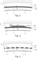
- Fig. 2 to Fig. 4 each show a side view (viewing direction according to the direction of the rotation axis of the tire) of a section of the tire and therefore views of circumferential sections of a shoulder flank 8a with an adjacent circumferential section of the radially outer end section of the adjoining side wall 5.
- the reference surface f 1 projected onto the respective shoulder flank 8a corresponds to a reference circle k 1 with a radius r 1 running around the shoulder flank 8a, the center of the reference circle k 1 lying on the rotation axis of the tire (not shown).
- the grinding indicator 9, 9', 9" is formed from a plurality of dome-shaped elevations 10 of the same design, each of which has a maximum thickness of 0.5 mm to 2.0 mm, in particular of at least 1.0 mm, determined perpendicular to the level of the shoulder flank 8a, and a circular base with a diameter of 0.5 mm to 2.0 mm, in particular of at least 1.0 mm, determined at the level of the shoulder flank 8a.
- the size of the maximum thickness is preferably at most 50% of the size of the diameter.
- the dome-shaped elevations 10 preferably each have the shape of a spherical segment, which is particularly preferably at most a hemisphere.
- the elevations 10, determined at the level of the shoulder flank 8a are formed at preferably matching distances of 0.5 mm to 1.5 mm, determined as minimum distances.
- the in Fig. 2 The grinding indicator 9 shown is formed from three circumferential rows 10a of elevations 10 and therefore has the shape of a circular ring.
- the in Fig. 3 The buffing indicator 9' shown differs from the buffing indicator 9 in that a group of three rows 10b of elevations 10 aligned in the circumferential direction, running next to and parallel to one another, is additionally provided locally.
- the rows 10b each have a length l b determined in the circumferential direction, wherein the length l b decreases from row 10b to row 10b, starting from the row 10b closest to the rows 10a, in particular to the same extent, so that one of the rows 10b has the greatest length l b , one of the rows 10b has the smallest length l b and one of the rows 10b has an average length l b .
- the row 10b with the greatest length l b projects beyond the row 10b with the average length l b at each end by an overhang ⁇ l 1 determined in the circumferential direction. Furthermore, the row 10b with the middle length l b projects beyond the row 10b with the smallest length l b at each end with a projection ⁇ l 2 determined in the circumferential direction, the size of which in the embodiment shown corresponds to the size of the projection ⁇ l 1 .
- the length l b is preferably 20.0 mm to 200.0 mm.
- Several groups of rows 10b can be provided at different circumferential positions of the buffing indicator 9. For example, four groups of rows 10b arranged offset by 90° to one another are provided.
- the in Fig. 4 The buffing indicator 9" shown differs from the buffing indicator 9 in that it is interrupted in sections, the resulting interruptions 11 free of elevations 10 being essentially parallelogram-shaped.
- the elevations 10 are preferably arranged exclusively in rows 10c running around the circumference and interrupted in sections in the circumference direction.
- the elevations 10 of immediately adjacent rows 10a, 10b, 10c are arranged with an offset determined in the circumferential direction, which corresponds to 50% of the diameter of an elevation 10.
- the elevations 10 are within a
- a roughening indicator is formed on at least one shoulder flank.
Landscapes
- Engineering & Computer Science (AREA)
- Mechanical Engineering (AREA)
- Tires In General (AREA)
Description
- Die Erfindung betrifft Nutzfahrzeugreifen, welcher kaltrunderneuerbar ist, mit Seitenwänden, Gürtellagen und einem profilierten Laufstreifen mit zu den Seitenwänden verlaufenden, außerhalb der Bodenaufstandsfläche befindlichen Schulterflanken, wobei auf zumindest einer Schulterflanke ein in Umfangsrichtung umlaufender, gegebenenfalls abschnittsweise unterbrochener, aus einer Vielzahl von Erhebungen gebildeter Abrauindikator zur Anzeige der Abrautiefe vorgesehen ist, wobei die Erhebungen gegenüber dem Niveau der Schulterflanke eine senkrecht zu diesem Niveau ermittelte maximale Stärke von 0,5 mm bis 2,0 mm aufweisen.
- Bei der Kaltrunderneuerung eines Nutzfahrzeugreifens wird der abgefahrene Laufstreifen abgetragen und nach Anrauen wird unter Verwendung einer unvulkanisierten Bindegummischicht ein neuer profilierter und bereits vulkanisierter oder vorvulkanisierter Laufstreifen bei einer Temperatur zwischen insbesondere 95°C und 115°C unter Vulkanisieren des Bindegummis aufgebracht. Ein Nutzfahrzeugreifen kann dabei mehrmals runderneuert werden. Zur Anzeige der für das Abrauen empfohlenen Abrautiefe ist es bekannt, auf den Schulterflanken des Laufstreifens Abrauindikatoren auszubilden.
- Ein Fahrzeugluftreifen eingangs genannter Art ist beispielsweise aus der
DE 10 2014 209 422 A1 bekannt. Der Reifen weist einen Laufstreifen mit zu den Seitenwänden verlaufenden Schulterflanken auf, wobei auf zumindest einer Schulterflanke schraffurartig ausgebildete, linienförmige Erhebungen oder linienförmige Vertiefungen vorgesehen sind, welche einen Abrauindikator bilden. Die Erhebungen oder Vertiefungen erstrecken sich jeweils ausgehend von einem Radius, welcher der Abrautiefe entspricht, über eine in radialer Richtung ermittelte Höhe nach radial außen, also in Richtung Laufstreifenperipherie. Die linienförmigen Erhebungen bzw. Vertiefungen schließen, ermittelt am Radius, mit der radialen Reifenrichtung einen Winkel von 5° bis 60° ein. Gemäß einer bevorzugten Ausführung weisen die Erhebungen gegenüber dem Niveau der Schulterflanke eine Stärke von 0,5 mm bis 2,0 mm auf. Beim Abrauen des Laufstreifens signalisiert das Verschwinden der Schraffur, dass die Abrautiefe erreicht ist. - Bedingt durch die Form und Anordnung der Erhebungen besteht beim bekannten Abrauindikator bei Bordsteinkontakt sowie durch die beim Fahren auftretenden Dauerbelastungen die Gefahr, dass die Erhebungen einreißen. Ferner verursachen die langgestreckten Erhebungen des Abrauindikators beim Fahren Luftverwirbelungen und erhöhen derart den dem abrollenden Reifen wirkenden Luftwiderstand.
- Der Erfindung liegt daher die Aufgabe zugrunde, bei einem Fahrzeugluftreifen eingangs genannter Art den Abrauindikator im Hinblick seinen Luftwiderstand und seine Rissbeständigkeit zu verbessern.
- Gelöst wird die gestellte Aufgabe erfindungsgemäß dadurch, dass die Erhebungen des Abrauindikators kuppelförmig sind und eine kreisförmige Grundfläche mit einem Durchmesser von 0,5 mm bis 2,0 mm aufweisen.
- Die gemäß der Erfindung vorgesehenen Erhebungen weisen somit eine aerodynamisch optimierte Form auf. Im Gegensatz zu den bekannten, linienförmigen Erhebungen neigen die gemäß der Erfindung kuppelförmig und mit kreisförmiger Grundfläche ausgeführten Erhebungen deutlich weniger dazu, Luftmoleküle während der Rotation des Reifens mitzureißen, wodurch der Luftwiderstand verringert ist. Ferner werden etwaige auf den Seitenwänden auftretende Verformungskräfte um die Erhebungen herum gleichmäßig verteilt, sodass Spannungsspitzen wirkungsvoll vermieden sind und die Rissbeständigkeit erhöht ist.
- Gemäß einer bevorzugten Ausführung sind Erhebungen vorgesehen, welche an die der Laufstreifenperipherie zugewandten Seite eines an der Schulterflanke umlaufenden Bezugskreises angrenzen, wobei der Bezugskreis von einer auf die jeweilige Schulterflanke projizierten Bezugsfläche stammt, welche, im Querschnitt des Reifens betrachtet, im Bereich innerhalb der Bodenaufstandsfläche parallel zur Laufstreifenperipherie verläuft sowie im Bereich axial außerhalb der Bodenaufstandsfläche ihrem Verlauf folgend bis zu den Schulterflanken fortgeführt ist und welche in der Reifenäquatorialebene von der radial äußersten Gürtellage in Richtung Laufstreifenperipherie einen in radialer Richtung ermittelten Abstand von bis zu 2,0 mm aufweist. An dieser Stelle ausgebildete Erhebungen befinden sich in einer zur Anzeige der Abrautiefe besonders vorteilhaften Position.
- Bei dieser Ausführung ist es ferner von Vorteil, wenn der Abstand, welchen die Bezugsfläche von der radial äußersten Gürtellage aufweist, mindestens 1,0 mm beträgt. Der Abrauindikator zeigt dadurch eine radial außerhalb der Gürtelgummierung liegende Abrautiefe an, sodass beim Abrauen die Wahrscheinlichkeit, dass die Gürtelgummierung versehentlich bzw. zu stark angeraut wird, verringert ist.
- Im Hinblick auf die Sichtbarkeit und die Rissbeständigkeit der Erhebungen ist es günstig, wenn der Durchmesser der kreisförmigen Grundflächen der Erhebungen und die maximale Stärke der Erhebungen jeweils mindestens 1,0 mm beträgt.
- Gemäß einer weiteren bevorzugten Ausführung beträgt die Größe der maximalen Stärke der Erhebungen höchstens 50% der Größe des Durchmessers der kreisförmigen Grundfläche der Erhebungen. Diese Maßnahme trägt ebenfalls zu einer guten Rissbeständigkeit der Erhebungen bei.
- Gemäß einer weiteren bevorzugten Ausführung beträgt die Größe der maximalen Stärke der Erhebungen mindestens 25% der Größe des Durchmessers der kreisförmigen Grundfläche der Erhebungen.
- Die auf den Seitenwänden beim Abrollen des Reifens auftretenden Verformungskräfte um die Erhebungen herum sind besonders gleichmäßig, wenn die Erhebungen jeweils die Form eines Kugelsegmentes, insbesondere höchstens einer Halbkugel, aufweisen. Spannungsspitzen werden dadurch besonders effektiv vermieden.
- Gemäß einer weiteren bevorzugten Ausführung sind Erhebungen vorgesehen, welche voneinander als Minimalabstände ermittelte Abstände von 0,5 mm bis 1,5 mm aufweisen, wobei vorzugsweise Erhebungen vorgesehen sind, welche voneinander übereinstimmende, als Minimalabstände ermittelten Abstände aufweisen, sodass eine sehr gute Sichtbarkeit des Abrauindikators sichergestellt ist.
- Ferner ist es von Vorteil, wenn die Erhebungen innerhalb eines Kreisringes mit einer senkrecht zur Umfangsrichtung ermittelte Breite von höchstens 20,0 mm ausgebildet sind. Dies ist im Hinblick auf den Luftwiderstand günstig.
- Gemäß einer weiteren bevorzugten Ausführung sind die Erhebungen derart ausgebildet, dass der Abrauindikator insgesamt die Form eines Kreisrings aufweist, wobei die Erhebungen vorzugsweise ausschließlich innerhalb einer Anzahl von in Umfangsrichtung umlaufenden Reihen vorgesehen sind. Durch die Kreisringform lässt sich der Abrauvorgang über den gesamten Reifenumfang ideal überwachen. In diesem Zusammenhang sind Erhebungen, welche in einer Anzahl von in Umfangsrichtung umlaufenden Reihen vorgesehen sind, besonders vorteilhaft.
- Gemäß einer alternativen bevorzugten Ausführung sind die Erhebungen derart ausgebildet, dass der Abrauindikator die Form eines abschnittsweise unterbrochenen Kreisrings aufweist, wobei die Erhebungen vorzugsweise ausschließlich in in Umfangsrichtung umlaufenden, in Umfangsrichtung abschnittsweise ununterbrochenen Reihen angeordnet sind. Auch diese Ausführung ist hinsichtlich Sichtbarkeit und Luftwiderstand des Abrauindikators vorteilhaft.
- Gemäß einer weiteren bevorzugten Ausführung umfasst der Abrauindikator eine Anzahl von in Umfangsrichtung ausgerichteten, neben und parallel zueinander verlaufende Reihen aus hintereinander angeordneten Erhebungen oder ist aus solchen Reihen gebildet, wobei die Reihen jeweils eine in Umfangsrichtung ermittelte Länge von vorzugsweise 20,0 mm bis 200,0 mm aufweisen. Mittels solcher Reihen lässt sich der Fortschritt des Abrauvorgangs gut mitverfolgen.
- Bei dieser Ausführung ist es ferner günstig, wenn einander benachbarte Reihen mit voneinander abweichenden Längen vorgesehen sind, wobei die Länge von Reihe zu Reihe in Richtung Laufstreifenperipherie in insbesondere gleichen Ausmaß abnimmt, wobei - jeweils bezogen auf zwei benachbarte Reihen - die Reihe mit der größten Länge die Reihe mit der kleineren Länge an jedem Ende mit übereinstimmenden Überstanden überragt.
- Bevorzugter Weise ist auf jeder Schulterflanke ein Abrauindikator ausgebildet.
- Weitere Merkmale, Vorteile und Einzelheiten der Erfindung werden nun anhand der Zeichnung, die schematisch Ausführungsbeispiele der Erfindung zeigt, näher beschrieben. Dabei zeigen
-
Fig. 1 einen schematischen Teilquerschnitt durch einen Nutzfahrzeugreifen im Bereich des Laufstreifens und des Gürtelverbandes, -
Fig. 2 eine Ansicht auf einen Umfangsabschnitt einer Schulterflanke des Nutzfahrzeugreifens mit einer ersten Ausführungsvariante der Erfindung, -
Fig. 3 eine Ansicht auf einen Umfangsabschnitt einer Schulterflanke des Nutzfahrzeugreifens mit einer zweiten Ausführungsvariante der Erfindung und -
Fig. 4 eine Ansicht auf einen Umfangsabschnitt einer Schulterflanke des Nutzfahrzeugreifens mit einer dritten Ausführungsvariante der Erfindung. - Die Erfindung befasst sich mit einem Abrauindikator zur Anzeige der Abrautiefe eines für die Kaltrunderneuerung vorgesehenen Nutzfahrzeugreifens.
- In
Fig. 1 sind von den Bauteilen des Nutzfahrzeugreifens ein Laufstreifen 1, ein Gürtelverband 2 mit vier Gürtellagen 2a, eine Karkasseinlage 3 und eine Innenschicht 4 sowie die radial äußeren Endabschnitte von Seitenwänden 5 gezeigt. Die Reifenäquatorialebene ist durch eine Linie A-A, die seitlichen Ränder des Laufstreifens 1 bzw. der Bodenaufstandsfläche des Laufstreifens 1 (gemäß E.T.R.T.O-Standard) sind durch zwei parallel zur Reifenäquatorialebene verlaufende Linien I angedeutet. - Der Laufstreifen 1 ist mit einer Profilierung versehen, welche im dargestellten Beispiel fünf auf Profiltiefe T1 ausgeführte Umfangsrillen 6 umfasst, sodass der Laufstreifen 1 vier mittlere Profilrippen 7 und zwei schulterseitige Profilrippen 8 aufweist. Die schulterseitigen Profilrippen 8 weisen außerhalb der Bodenaufstandsfläche jeweils eine bis zum seitlichen Rand der Bodenaufstandsfläche (Linie I) reichende, zur entsprechenden Seitenwand 5 verlaufende Schulterflanke 8a auf.
- Die eingangs bereits erwähnte Abrautiefe ist in
Fig. 1 durch eine Bezugsfläche f1 gekennzeichnet. Die Bezugsfläche f1 verläuft, im Reifenquerschnitt betrachtet, radial innerhalb der auf Profiltiefe T1 ausgeführten Umfangsrillen 6, im Bereich zwischen den Linien I parallel zur Laufstreifenperipherie und ist im Bereich axial außerhalb der Linien I ihrem Verlauf folgend bis zu den Schulterflanken 8a fortgeführt, wobei die Bezugsfläche f1 in der Reifenäquatorialebene (Linie A-A) von der radial äußersten Gürtellage 2a, ermittelt in radialer Richtung sowie in Richtung Laufstreifenperipherie, einen Abstand a1 von bis zu 2,0 mm aufweist. Bevorzugter Weise beträgt der Abstand a1 mindestens 1,0 mm. Die Fortführung der Bezugsfläche f1 in die Bereiche axial außerhalb der Linien l erfolgt, im Reifenquerschnitt betrachtet, mit jenem Krümmungsradius, welcher der lokalen Krümmung der Bezugsfläche f1 im Schnittpunkt mit der Linie l am besten angenähert ist. -
Fig. 2 bis Fig. 4 zeigen je eine Seitenansicht (Sichtrichtung gemäß der Richtung der Rotationsachse des Reifens) auf einen Abschnitt des Reifens und daher Ansichten auf Umfangsabschnitte einer Schulterflanke 8a mit angrenzendem Umfangsabschnitt des radial äußeren Endabschnittes der anschließenden Seitenwand 5. Die auf die jeweilige Schulterflanke 8a projizierte Bezugsfläche f1 entspricht einem auf der Schulterflanke 8a umlaufenden Bezugskreis k1 mit einem Radius r1, wobei der Mittelpunkt des Bezugskreises k1 auf der nicht gezeigten Rotationsachse des Reifens liegt. Auf jeder Schulterflanke 8a ist angrenzend an den Bezugskreis k1 im Bereich zwischen dem Bezugskreis k1 und dem seitlichen Rand der Bodenaufstandsfläche (Linie l) ein in Umfangsrichtung umlaufender, gegebenenfalls abschnittsweise unterbrochener Abrauindikator 9 (Fig. 2 ), 9' (Fig. 3 ), 9" (Fig. 4 ) zur Anzeige der Abrautiefe ausgebildet. Der Abrauindikator 9, 9', 9" ist aus einer Vielzahl von übereinstimmend ausgeführten kuppelförmigen Erhebungen 10 gebildet, welche jeweils eine senkrecht zum Niveau der Schulterflanke 8a ermittelte maximale Stärke von 0,5 mm bis 2,0 mm, insbesondere von mindestens 1,0 mm, und eine kreisförmige Grundfläche mit einem am Niveau der Schulterflanke 8a ermittelten Durchmesser von 0,5 mm bis 2,0 mm, insbesondere von mindestens 1,0 mm, aufweisen. Bevorzugter Weise beträgt die Größe der maximalen Stärke höchstens 50% der Größe des Durchmessers. Ferner weisen die kuppelförmigen Erhebungen 10 bevorzugt jeweils die Form eines Kugelsegmentes auf, welches besonders bevorzugt höchstens eine Halbkugel ist. Ferner sind die Erhebungen 10, ermittelt am Niveau der Schulterflanke 8a, unter vorzugsweise übereinstimmenden als Minimalabstände ermittelten Abständen von 0,5 mm bis 1,5 mm ausgebildet. - Der in
Fig. 2 gezeigte Abrauindikator 9 ist aus drei in Umfangsrichtung umlaufenden Reihen 10a von Erhebungen 10 gebildet und weist daher die Form eines Kreisrings auf. - Der in
Fig. 3 dargestellte Abrauindikator 9' unterscheidet sich vom Abrauindikator 9 dadurch, dass lokal zusätzlich eine Gruppe aus drei in Umfangsrichtung ausgerichteten, neben und parallel zueinander verlaufenden Reihen 10b aus Erhebungen 10 vorgesehen ist. Die Reihen 10b weisen jeweils eine in Umfangsrichtung ermittelte Länge lb auf, wobei die Länge lb ausgehend von der zu den Reihen 10a nächstliegenden Reihe 10b von Reihe 10b zu Reihe 10b in insbesondere gleichem Ausmaß abnimmt, sodass eine der Reihen 10b die größte Länge lb, eine der Reihen 10b die kleinste Länge lb und eine der Reihen 10b eine mittlere Länge lb aufweist. Die Reihe 10b mit der größten Länge lb überragt die Reihe 10b mit der mittleren Länge lb an jedem Ende mit einem in Umfangsrichtung ermittelten Überstand Δl1. Ferner überragt die Reihe 10b mit der mittleren Länge lb die Reihe 10b mit der kleinsten Länge lb an jedem Ende mit einem in Umfangsrichtung ermittelten Überstand Δl2, dessen Größe beim gezeigten Ausführungsbeispiel mit der Größe des Überstandes Δl1 übereinstimmt. Die Länge lb beträgt vorzugsweise 20,0 mm bis 200,0 mm. Es können mehrere Gruppen von Reihen 10b an unterschiedlichen Umfangspositionen des Abrauindikators 9 vorgesehen sein. Beispielsweise sind vier um 90° zueinander versetzt angeordnete Gruppen von Reihen 10b vorgesehen. - Der in
Fig. 4 gezeigte Abrauindikator 9" unterscheidet sich vom Abrauindikator 9 dadurch, dass er abschnittsweise unterbrochen ist, wobei die resultierenden von Erhebungen 10 freien Unterbrechungen 11 im Wesentlichen parallelogrammförmig sind. Insbesondere sind die Erhebungen 10 vorzugsweise ausschließlich in in Umfangsrichtung umlaufenden, in Umfangsrichtung abschnittsweise unterbrochenen Reihen 10c angeordnet. - Bei sämtlichen beschriebenen Varianten sind die Erhebungen 10 unmittelbar benachbarter Reihen 10a, 10b, 10c unter einem in Umfangsrichtung ermittelten Versatz, welcher 50% des Durchmessers einer Erhebung 10 entspricht, angeordnet. Bevorzugter Weise sind die Erhebungen 10 innerhalb eines
- Kreisringes mit einer senkrecht zur Umfangsrichtung ermittelte Breite b1 (
Fig. 2 bis Fig. 4 ) von höchstens 20,0 mm ausgebildet. - Die Erfindung ist auf die beschriebenen Ausführungsbeispiele nicht beschränkt, wobei der Schutzumfang der Erfindung durch die Ansprüche definiert ist.
- Es ist auf zumindest einer Schulterflanke ein Abrauindikator ausgebildet.
-
- 1
- Laufstreifen
- 2
- Gürtelverband
- 2a
- Gürtellage
- 3
- Karkasseinlage
- 4
- Innenschicht
- 5
- Seitenwand
- 6
- Umfangsrille
- 7
- mittlere Profilrippe
- 8
- schulterseitige Profilrippe
- 8a
- Schulterflanke
- 9, 9', 9"
- Abrauindikator
- 10
- Erhebung
- 10a, 10b,
- 10c.Reihe
- 11
- Unterbrechung
- A-A
- Linie (Reifenäquatorialebene)
- a1
- Abstand
- b1
- Breite
- f1
- Bezugsfläche (Abrautiefe)
- k1
- Bezugskreis (Abrautiefe)
- l
- Linie (seitlicher Rand der Bodenaufstandsfläche)
- lb
- Länge
- Δl1, Δl2
- Überstand
- r1
- Radius
- T1
- Profiltiefe
Claims (15)
- Nutzfahrzeugreifen, welcher kaltrunderneuerbar ist, mit Seitenwänden (5), Gürtellagen (2a) und einem profilierten Laufstreifen (1) mit zu den Seitenwänden (5) verlaufenden, außerhalb der Bodenaufstandsfläche befindlichen Schulterflanken (8a), wobei auf zumindest einer Schulterflanke (8a) ein in Umfangsrichtung umlaufender, gegebenenfalls abschnittsweise unterbrochener, aus einer Vielzahl von Erhebungen (10) gebildeter Abrauindikator (9, 9', 9") zur Anzeige der Abrautiefe vorgesehen ist, wobei die Erhebungen (10) gegenüber dem Niveau der Schulterflanke (8a) eine senkrecht zu diesem Niveau ermittelte maximale Stärke von 0,5 mm bis 2,0 mm aufweisen,
dadurch gekennzeichnet,
dass die Erhebungen (10) des Abrauindikators (9, 9', 9") kuppelförmig sind und eine kreisförmige Grundfläche mit einem Durchmesser von 0,5 mm bis 2,0 mm aufweisen. - Nutzfahrzeugreifen nach Anspruch 1, dadurch gekennzeichnet, dass Erhebungen (10) vorgesehen sind, welche an die der Laufstreifenperipherie zugewandten Seite eines an der Schulterflanke (8a) umlaufenden Bezugskreises (k1) angrenzen, wobei der Bezugskreis (k1) von einer auf die jeweilige Schulterflanke (8a) projizierten Bezugsfläche (f1) stammt,welche, im Querschnitt des Reifens betrachtet, im Bereich innerhalb der Bodenaufstandsfläche parallel zur Laufstreifenperipherie verläuft sowie im Bereich axial außerhalb der Bodenaufstandsfläche ihrem Verlauf folgend bis zu den Schulterflanken (8a) fortgeführt ist undwelche in der Reifenäquatorialebene (Linie A-A) von der radial äußersten Gürtellage (2a) in Richtung Laufstreifenperipherie einen in radialer Richtung ermittelten Abstand (a1) von bis zu 2,0 mm aufweist.
- Nutzfahrzeugreifen nach Anspruch 2, dadurch gekennzeichnet, dass der Abstand (a1), welchen die Bezugsfläche (f1) von der radial äußersten Gürtellage (2a) aufweist, mindestens 1,0 mm beträgt.
- Nutzfahrzeugreifen nach einem der Ansprüche 1 bis 3, dadurch gekennzeichnet, dass der Durchmesser der kreisförmigen Grundflächen der Erhebungen (10) mindestens 1,0 mm beträgt.
- Nutzfahrzeugreifen nach einem der Ansprüche 1 bis 4, dadurch gekennzeichnet, dass die maximale Stärke der Erhebungen (10) mindestens 1,0 mm beträgt.
- Nutzfahrzeugreifen nach einem der Ansprüche 1 bis 5, dadurch gekennzeichnet, dass die Größe der maximalen Stärke der Erhebungen (10) höchstens 50% der Größe des Durchmessers der kreisförmigen Grundfläche der Erhebungen (10) beträgt.
- Nutzfahrzeugreifen nach einem der Ansprüche 1 bis 6, dadurch gekennzeichnet, dass die Größe der maximalen Stärke der Erhebungen (10) mindestens 25% der Größe des Durchmessers der kreisförmigen Grundfläche der Erhebungen (10) beträgt.
- Nutzfahrzeugreifen nach einem der Ansprüche 1 bis 7, dadurch gekennzeichnet, dass die Erhebungen (10) jeweils die Form eines Kugelsegmentes, insbesondere höchstens einer Halbkugel, aufweisen.
- Nutzfahrzeugreifen nach einem der Ansprüche 1 bis 8, dadurch gekennzeichnet, dass Erhebungen (10) vorgesehen sind, welche voneinander als Minimalabstände ermittelte Abstände von 0,5 mm bis 1,5 mm aufweisen, wobei vorzugsweise Erhebungen (10) vorgesehen sind, welche voneinander übereinstimmende, als Minimalabstände ermittelten Abstände aufweisen.
- Nutzfahrzeugreifen nach einem der Ansprüche 1 bis 9, dadurch gekennzeichnet, dass die Erhebungen (10) innerhalb eines Kreisringes mit einer senkrecht zur Umfangsrichtung ermittelte Breite (b1) von höchstens 20,0 mm ausgebildet sind.
- Nutzfahrzeugreifen nach einem der Ansprüche 1 bis 10, dadurch gekennzeichnet, dass die Erhebungen (10) derart ausgebildet sind, dass der Abrauindikator (9) insgesamt die Form eines Kreisrings aufweist, wobei die Erhebungen (10) vorzugsweise ausschließlich innerhalb einer Anzahl von in Umfangsrichtung umlaufenden Reihen (10a) vorgesehen sind.
- Nutzfahrzeugreifen nach einem der Ansprüche 1 bis 10, dadurch gekennzeichnet, dass die Erhebungen (10) derart ausgebildet sind, dass der Abrauindikator (9") die Form eines abschnittsweise unterbrochenen Kreisrings aufweist, wobei die Erhebungen (10) vorzugsweise ausschließlich in in Umfangsrichtung umlaufenden, in Umfangsrichtung abschnittsweise ununterbrochenen Reihen (10c) angeordnet sind.
- Nutzfahrzeugreifen nach einem der Ansprüche 1 bis 12, dadurch gekennzeichnet, dass der Abrauindikator (9`) eine Anzahl von in Umfangsrichtung ausgerichteten, neben und parallel zueinander verlaufende Reihen (10b) aus hintereinander angeordneten Erhebungen (10) umfasst oder aus solchen Reihen (10b) gebildet ist, wobei die Reihen (10b) jeweils eine in Umfangsrichtung ermittelte Länge (lb) von vorzugsweise 20,0 mm bis 200,0 mm aufweisen.
- Nutzfahrzeugreifen nach Anspruch 13, dadurch gekennzeichnet, dass einander benachbarte Reihen (10b) mit voneinander abweichenden Längen (lb) vorgesehen sind, wobei die Länge (lb) von Reihe (10b) zu Reihe (10b) in Richtung Laufstreifenperipherie in insbesondere gleichen Ausmaß abnimmt, wobei - jeweils bezogen auf zwei benachbarte Reihen (10b) - die Reihe (10b) mit der größten Länge (lb) die Reihe (10b) mit der kleineren Länge (lb) an jedem Ende mit übereinstimmenden Überstanden (Δl1, Δl2) überragt.
- Nutzfahrzeugreifen nach einem der Ansprüche 1 bis 14, dadurch gekennzeichnet, dass auf jeder Schulterflanke (8a) ein Abrauindikator (9, 9', 9") ausgebildet ist.
Applications Claiming Priority (2)
| Application Number | Priority Date | Filing Date | Title |
|---|---|---|---|
| DE102020214761.2A DE102020214761A1 (de) | 2020-11-25 | 2020-11-25 | Nutzfahrzeugreifen |
| PCT/DE2021/200169 WO2022111770A1 (de) | 2020-11-25 | 2021-11-02 | Nutzfahrzeugreifen |
Publications (2)
| Publication Number | Publication Date |
|---|---|
| EP4251434A1 EP4251434A1 (de) | 2023-10-04 |
| EP4251434B1 true EP4251434B1 (de) | 2025-01-08 |
Family
ID=78621610
Family Applications (1)
| Application Number | Title | Priority Date | Filing Date |
|---|---|---|---|
| EP21806985.4A Active EP4251434B1 (de) | 2020-11-25 | 2021-11-02 | Nutzfahrzeugreifen |
Country Status (7)
| Country | Link |
|---|---|
| US (1) | US12539720B2 (de) |
| EP (1) | EP4251434B1 (de) |
| CN (1) | CN116547130A (de) |
| DE (1) | DE102020214761A1 (de) |
| ES (1) | ES3020289T3 (de) |
| PL (1) | PL4251434T3 (de) |
| WO (1) | WO2022111770A1 (de) |
Family Cites Families (9)
| Publication number | Priority date | Publication date | Assignee | Title |
|---|---|---|---|---|
| JP2764610B2 (ja) * | 1989-05-24 | 1998-06-11 | 東洋ゴム工業株式会社 | 研削許容限界マークを備えた空気入りラジアルタイヤ |
| JPH11321243A (ja) * | 1998-05-18 | 1999-11-24 | Bridgestone Corp | 多数の半球状の突起よりなる環状装飾体を備えた空気入りタイヤ |
| US20040084120A1 (en) | 2001-11-30 | 2004-05-06 | Jesse Arnold | Tire with marked layers |
| US9174498B2 (en) * | 2011-09-22 | 2015-11-03 | The Yokohama Rubber Co., Ltd. | Pneumatic tire |
| JP5482758B2 (ja) * | 2011-09-28 | 2014-05-07 | 横浜ゴム株式会社 | 空気入りタイヤ |
| FR2998216B1 (fr) * | 2012-11-19 | 2015-01-16 | Michelin & Cie | Indicateur d'usure pour pneu genie civil |
| DE102014209422A1 (de) | 2014-05-19 | 2015-11-19 | Continental Reifen Deutschland Gmbh | Fahrzeugluftreifen |
| DE102014210715A1 (de) * | 2014-06-05 | 2015-12-17 | Continental Reifen Deutschland Gmbh | Fahrzeugluftreifen |
| FR3057209A1 (fr) * | 2016-10-11 | 2018-04-13 | Compagnie Generale Des Etablissements Michelin | Pneumatique pourvu d’un anneau texture |
-
2020
- 2020-11-25 DE DE102020214761.2A patent/DE102020214761A1/de active Pending
-
2021
- 2021-11-02 PL PL21806985.4T patent/PL4251434T3/pl unknown
- 2021-11-02 US US18/254,454 patent/US12539720B2/en active Active
- 2021-11-02 ES ES21806985T patent/ES3020289T3/es active Active
- 2021-11-02 WO PCT/DE2021/200169 patent/WO2022111770A1/de not_active Ceased
- 2021-11-02 CN CN202180079298.8A patent/CN116547130A/zh active Pending
- 2021-11-02 EP EP21806985.4A patent/EP4251434B1/de active Active
Also Published As
| Publication number | Publication date |
|---|---|
| EP4251434A1 (de) | 2023-10-04 |
| US12539720B2 (en) | 2026-02-03 |
| DE102020214761A1 (de) | 2022-05-25 |
| ES3020289T3 (en) | 2025-05-22 |
| US20240001635A1 (en) | 2024-01-04 |
| CN116547130A (zh) | 2023-08-04 |
| PL4251434T3 (pl) | 2025-04-14 |
| WO2022111770A1 (de) | 2022-06-02 |
Similar Documents
| Publication | Publication Date | Title |
|---|---|---|
| EP2067636B1 (de) | Fahrzeugluftreifen | |
| EP2070731B1 (de) | Fahrzeugluftreifen | |
| EP2803501B1 (de) | Fahrzeugluftreifen | |
| EP3186097B1 (de) | Fahrzeugluftreifen | |
| EP4251434B1 (de) | Nutzfahrzeugreifen | |
| DE102017209677A1 (de) | Verfahren zur Ermittlung von Spannungsänderungen in einer Gürtellage von Fahrzeugreifen und Nutzfahrzeugreifen als Solcher | |
| DE4220677A1 (de) | Luftreifen fuer personen-kraftwagen | |
| DE112019005505B4 (de) | Luftreifen | |
| EP2957422B1 (de) | Fahrzeugluftreifen | |
| EP2072288B1 (de) | Fahrzeugluftreifen | |
| EP4011648B1 (de) | Fahrzeugluftreifen | |
| EP3224060A1 (de) | Fahrzeugluftreifen | |
| DE69608142T2 (de) | Landwirtschaftsreifen für gewerbliche zwecke | |
| EP2403724B1 (de) | Fahrzeugluftreifen | |
| EP3980279B1 (de) | Fahrzeugluftreifen | |
| EP3335907B1 (de) | Fahrzeugluftreifen | |
| EP2143572B1 (de) | Fahrzeugluftreifen | |
| EP3269568B1 (de) | Fahrzeugluftreifen für den winter- und ganzjahreseinsatz | |
| EP4434773B1 (de) | Fahrzeugluftreifen | |
| EP2895339B1 (de) | Fahrzeugluftreifen | |
| EP2078622B1 (de) | Fahrzeugluftreifen | |
| EP3554819B1 (de) | Laufstreifen für die kaltrunderneuerung eines nutzfahrzeugreifens und nutzfahrzeugreifen | |
| EP2019757A1 (de) | Fahrzeugluftreifen mit gürtelbandage | |
| EP1346852B1 (de) | Fahrzeugluftreifen | |
| EP4722001A1 (de) | Fahrzeugreifen |
Legal Events
| Date | Code | Title | Description |
|---|---|---|---|
| STAA | Information on the status of an ep patent application or granted ep patent |
Free format text: STATUS: UNKNOWN |
|
| STAA | Information on the status of an ep patent application or granted ep patent |
Free format text: STATUS: THE INTERNATIONAL PUBLICATION HAS BEEN MADE |
|
| PUAI | Public reference made under article 153(3) epc to a published international application that has entered the european phase |
Free format text: ORIGINAL CODE: 0009012 |
|
| STAA | Information on the status of an ep patent application or granted ep patent |
Free format text: STATUS: REQUEST FOR EXAMINATION WAS MADE |
|
| 17P | Request for examination filed |
Effective date: 20230626 |
|
| AK | Designated contracting states |
Kind code of ref document: A1 Designated state(s): AL AT BE BG CH CY CZ DE DK EE ES FI FR GB GR HR HU IE IS IT LI LT LU LV MC MK MT NL NO PL PT RO RS SE SI SK SM TR |
|
| DAV | Request for validation of the european patent (deleted) | ||
| DAX | Request for extension of the european patent (deleted) | ||
| RAP3 | Party data changed (applicant data changed or rights of an application transferred) |
Owner name: CONTINENTAL REIFEN DEUTSCHLAND GMBH |
|
| REG | Reference to a national code |
Ref country code: DE Free format text: PREVIOUS MAIN CLASS: B60C0013000000 Ipc: B29D0030580000 Ref country code: DE Ref legal event code: R079 Ref document number: 502021006386 Country of ref document: DE Free format text: PREVIOUS MAIN CLASS: B60C0013000000 Ipc: B29D0030580000 |
|
| GRAP | Despatch of communication of intention to grant a patent |
Free format text: ORIGINAL CODE: EPIDOSNIGR1 |
|
| GRAP | Despatch of communication of intention to grant a patent |
Free format text: ORIGINAL CODE: EPIDOSNIGR1 |
|
| STAA | Information on the status of an ep patent application or granted ep patent |
Free format text: STATUS: GRANT OF PATENT IS INTENDED |
|
| RIC1 | Information provided on ipc code assigned before grant |
Ipc: B29D 30/54 20060101ALI20240523BHEP Ipc: B60C 13/00 20060101ALI20240523BHEP Ipc: B29D 30/58 20060101AFI20240523BHEP |
|
| INTG | Intention to grant announced |
Effective date: 20240614 |
|
| GRAS | Grant fee paid |
Free format text: ORIGINAL CODE: EPIDOSNIGR3 |
|
| P01 | Opt-out of the competence of the unified patent court (upc) registered |
Free format text: CASE NUMBER: APP_56412/2024 Effective date: 20241016 |
|
| GRAA | (expected) grant |
Free format text: ORIGINAL CODE: 0009210 |
|
| STAA | Information on the status of an ep patent application or granted ep patent |
Free format text: STATUS: THE PATENT HAS BEEN GRANTED |
|
| AK | Designated contracting states |
Kind code of ref document: B1 Designated state(s): AL AT BE BG CH CY CZ DE DK EE ES FI FR GB GR HR HU IE IS IT LI LT LU LV MC MK MT NL NO PL PT RO RS SE SI SK SM TR |
|
| REG | Reference to a national code |
Ref country code: GB Ref legal event code: FG4D Free format text: NOT ENGLISH |
|
| REG | Reference to a national code |
Ref country code: CH Ref legal event code: EP |
|
| REG | Reference to a national code |
Ref country code: DE Ref legal event code: R096 Ref document number: 502021006386 Country of ref document: DE |
|
| REG | Reference to a national code |
Ref country code: IE Ref legal event code: FG4D Free format text: LANGUAGE OF EP DOCUMENT: GERMAN |
|
| REG | Reference to a national code |
Ref country code: NL Ref legal event code: FP |
|
| REG | Reference to a national code |
Ref country code: LT Ref legal event code: MG9D |
|
| REG | Reference to a national code |
Ref country code: ES Ref legal event code: FG2A Ref document number: 3020289 Country of ref document: ES Kind code of ref document: T3 Effective date: 20250522 |
|
| PG25 | Lapsed in a contracting state [announced via postgrant information from national office to epo] |
Ref country code: RS Free format text: LAPSE BECAUSE OF FAILURE TO SUBMIT A TRANSLATION OF THE DESCRIPTION OR TO PAY THE FEE WITHIN THE PRESCRIBED TIME-LIMIT Effective date: 20250408 |
|
| PG25 | Lapsed in a contracting state [announced via postgrant information from national office to epo] |
Ref country code: FI Free format text: LAPSE BECAUSE OF FAILURE TO SUBMIT A TRANSLATION OF THE DESCRIPTION OR TO PAY THE FEE WITHIN THE PRESCRIBED TIME-LIMIT Effective date: 20250108 |
|
| PG25 | Lapsed in a contracting state [announced via postgrant information from national office to epo] |
Ref country code: IS Free format text: LAPSE BECAUSE OF FAILURE TO SUBMIT A TRANSLATION OF THE DESCRIPTION OR TO PAY THE FEE WITHIN THE PRESCRIBED TIME-LIMIT Effective date: 20250508 Ref country code: NO Free format text: LAPSE BECAUSE OF FAILURE TO SUBMIT A TRANSLATION OF THE DESCRIPTION OR TO PAY THE FEE WITHIN THE PRESCRIBED TIME-LIMIT Effective date: 20250408 |
|
| PG25 | Lapsed in a contracting state [announced via postgrant information from national office to epo] |
Ref country code: HR Free format text: LAPSE BECAUSE OF FAILURE TO SUBMIT A TRANSLATION OF THE DESCRIPTION OR TO PAY THE FEE WITHIN THE PRESCRIBED TIME-LIMIT Effective date: 20250108 |
|
| PG25 | Lapsed in a contracting state [announced via postgrant information from national office to epo] |
Ref country code: PT Free format text: LAPSE BECAUSE OF FAILURE TO SUBMIT A TRANSLATION OF THE DESCRIPTION OR TO PAY THE FEE WITHIN THE PRESCRIBED TIME-LIMIT Effective date: 20250508 Ref country code: LV Free format text: LAPSE BECAUSE OF FAILURE TO SUBMIT A TRANSLATION OF THE DESCRIPTION OR TO PAY THE FEE WITHIN THE PRESCRIBED TIME-LIMIT Effective date: 20250108 |
|
| PG25 | Lapsed in a contracting state [announced via postgrant information from national office to epo] |
Ref country code: GR Free format text: LAPSE BECAUSE OF FAILURE TO SUBMIT A TRANSLATION OF THE DESCRIPTION OR TO PAY THE FEE WITHIN THE PRESCRIBED TIME-LIMIT Effective date: 20250409 Ref country code: BG Free format text: LAPSE BECAUSE OF FAILURE TO SUBMIT A TRANSLATION OF THE DESCRIPTION OR TO PAY THE FEE WITHIN THE PRESCRIBED TIME-LIMIT Effective date: 20250108 |
|
| PG25 | Lapsed in a contracting state [announced via postgrant information from national office to epo] |
Ref country code: SE Free format text: LAPSE BECAUSE OF FAILURE TO SUBMIT A TRANSLATION OF THE DESCRIPTION OR TO PAY THE FEE WITHIN THE PRESCRIBED TIME-LIMIT Effective date: 20250108 |
|
| PG25 | Lapsed in a contracting state [announced via postgrant information from national office to epo] |
Ref country code: SM Free format text: LAPSE BECAUSE OF FAILURE TO SUBMIT A TRANSLATION OF THE DESCRIPTION OR TO PAY THE FEE WITHIN THE PRESCRIBED TIME-LIMIT Effective date: 20250108 |
|
| REG | Reference to a national code |
Ref country code: DE Ref legal event code: R097 Ref document number: 502021006386 Country of ref document: DE |
|
| PG25 | Lapsed in a contracting state [announced via postgrant information from national office to epo] |
Ref country code: DK Free format text: LAPSE BECAUSE OF FAILURE TO SUBMIT A TRANSLATION OF THE DESCRIPTION OR TO PAY THE FEE WITHIN THE PRESCRIBED TIME-LIMIT Effective date: 20250108 |
|
| PG25 | Lapsed in a contracting state [announced via postgrant information from national office to epo] |
Ref country code: CZ Free format text: LAPSE BECAUSE OF FAILURE TO SUBMIT A TRANSLATION OF THE DESCRIPTION OR TO PAY THE FEE WITHIN THE PRESCRIBED TIME-LIMIT Effective date: 20250108 Ref country code: EE Free format text: LAPSE BECAUSE OF FAILURE TO SUBMIT A TRANSLATION OF THE DESCRIPTION OR TO PAY THE FEE WITHIN THE PRESCRIBED TIME-LIMIT Effective date: 20250108 |
|
| PG25 | Lapsed in a contracting state [announced via postgrant information from national office to epo] |
Ref country code: RO Free format text: LAPSE BECAUSE OF FAILURE TO SUBMIT A TRANSLATION OF THE DESCRIPTION OR TO PAY THE FEE WITHIN THE PRESCRIBED TIME-LIMIT Effective date: 20250108 |
|
| PG25 | Lapsed in a contracting state [announced via postgrant information from national office to epo] |
Ref country code: SK Free format text: LAPSE BECAUSE OF FAILURE TO SUBMIT A TRANSLATION OF THE DESCRIPTION OR TO PAY THE FEE WITHIN THE PRESCRIBED TIME-LIMIT Effective date: 20250108 |
|
| PLBE | No opposition filed within time limit |
Free format text: ORIGINAL CODE: 0009261 |
|
| STAA | Information on the status of an ep patent application or granted ep patent |
Free format text: STATUS: NO OPPOSITION FILED WITHIN TIME LIMIT |
|
| PGFP | Annual fee paid to national office [announced via postgrant information from national office to epo] |
Ref country code: NL Payment date: 20251119 Year of fee payment: 5 |
|
| 26N | No opposition filed |
Effective date: 20251009 |
|
| PGFP | Annual fee paid to national office [announced via postgrant information from national office to epo] |
Ref country code: DE Payment date: 20251130 Year of fee payment: 5 |
|
| PGFP | Annual fee paid to national office [announced via postgrant information from national office to epo] |
Ref country code: AT Payment date: 20260113 Year of fee payment: 5 |
|
| PGFP | Annual fee paid to national office [announced via postgrant information from national office to epo] |
Ref country code: PL Payment date: 20251024 Year of fee payment: 5 |
|
| PG25 | Lapsed in a contracting state [announced via postgrant information from national office to epo] |
Ref country code: IT Free format text: LAPSE BECAUSE OF FAILURE TO SUBMIT A TRANSLATION OF THE DESCRIPTION OR TO PAY THE FEE WITHIN THE PRESCRIBED TIME-LIMIT Effective date: 20250108 |
|
| PGFP | Annual fee paid to national office [announced via postgrant information from national office to epo] |
Ref country code: ES Payment date: 20251229 Year of fee payment: 5 |