EP4250436A1 - Batterieheizvorrichtung und steuerungsverfahren, steuerschaltung und leistungsvorrichtung dafür - Google Patents
Batterieheizvorrichtung und steuerungsverfahren, steuerschaltung und leistungsvorrichtung dafür Download PDFInfo
- Publication number
- EP4250436A1 EP4250436A1 EP21955578.6A EP21955578A EP4250436A1 EP 4250436 A1 EP4250436 A1 EP 4250436A1 EP 21955578 A EP21955578 A EP 21955578A EP 4250436 A1 EP4250436 A1 EP 4250436A1
- Authority
- EP
- European Patent Office
- Prior art keywords
- tube switch
- traction battery
- leg
- energy storage
- storage element
- Prior art date
- Legal status (The legal status is an assumption and is not a legal conclusion. Google has not performed a legal analysis and makes no representation as to the accuracy of the status listed.)
- Pending
Links
Images


Classifications
-
- B—PERFORMING OPERATIONS; TRANSPORTING
- B60—VEHICLES IN GENERAL
- B60L—PROPULSION OF ELECTRICALLY-PROPELLED VEHICLES; SUPPLYING ELECTRIC POWER FOR AUXILIARY EQUIPMENT OF ELECTRICALLY-PROPELLED VEHICLES; ELECTRODYNAMIC BRAKE SYSTEMS FOR VEHICLES IN GENERAL; MAGNETIC SUSPENSION OR LEVITATION FOR VEHICLES; MONITORING OPERATING VARIABLES OF ELECTRICALLY-PROPELLED VEHICLES; ELECTRIC SAFETY DEVICES FOR ELECTRICALLY-PROPELLED VEHICLES
- B60L58/00—Methods or circuit arrangements for monitoring or controlling batteries or fuel cells, specially adapted for electric vehicles
- B60L58/10—Methods or circuit arrangements for monitoring or controlling batteries or fuel cells, specially adapted for electric vehicles for monitoring or controlling batteries
- B60L58/24—Methods or circuit arrangements for monitoring or controlling batteries or fuel cells, specially adapted for electric vehicles for monitoring or controlling batteries for controlling the temperature of batteries
- B60L58/27—Methods or circuit arrangements for monitoring or controlling batteries or fuel cells, specially adapted for electric vehicles for monitoring or controlling batteries for controlling the temperature of batteries by heating
-
- B—PERFORMING OPERATIONS; TRANSPORTING
- B60—VEHICLES IN GENERAL
- B60L—PROPULSION OF ELECTRICALLY-PROPELLED VEHICLES; SUPPLYING ELECTRIC POWER FOR AUXILIARY EQUIPMENT OF ELECTRICALLY-PROPELLED VEHICLES; ELECTRODYNAMIC BRAKE SYSTEMS FOR VEHICLES IN GENERAL; MAGNETIC SUSPENSION OR LEVITATION FOR VEHICLES; MONITORING OPERATING VARIABLES OF ELECTRICALLY-PROPELLED VEHICLES; ELECTRIC SAFETY DEVICES FOR ELECTRICALLY-PROPELLED VEHICLES
- B60L1/00—Supplying electric power to auxiliary equipment of vehicles
- B60L1/02—Supplying electric power to auxiliary equipment of vehicles to electric heating circuits
-
- B—PERFORMING OPERATIONS; TRANSPORTING
- B60—VEHICLES IN GENERAL
- B60L—PROPULSION OF ELECTRICALLY-PROPELLED VEHICLES; SUPPLYING ELECTRIC POWER FOR AUXILIARY EQUIPMENT OF ELECTRICALLY-PROPELLED VEHICLES; ELECTRODYNAMIC BRAKE SYSTEMS FOR VEHICLES IN GENERAL; MAGNETIC SUSPENSION OR LEVITATION FOR VEHICLES; MONITORING OPERATING VARIABLES OF ELECTRICALLY-PROPELLED VEHICLES; ELECTRIC SAFETY DEVICES FOR ELECTRICALLY-PROPELLED VEHICLES
- B60L53/00—Methods of charging batteries, specially adapted for electric vehicles; Charging stations or on-board charging equipment therefor; Exchange of energy storage elements in electric vehicles
- B60L53/20—Methods of charging batteries, specially adapted for electric vehicles; Charging stations or on-board charging equipment therefor; Exchange of energy storage elements in electric vehicles characterised by converters located in the vehicle
- B60L53/22—Constructional details or arrangements of charging converters specially adapted for charging electric vehicles
-
- H—ELECTRICITY
- H01—ELECTRIC ELEMENTS
- H01M—PROCESSES OR MEANS, e.g. BATTERIES, FOR THE DIRECT CONVERSION OF CHEMICAL ENERGY INTO ELECTRICAL ENERGY
- H01M10/00—Secondary cells; Manufacture thereof
- H01M10/60—Heating or cooling; Temperature control
- H01M10/61—Types of temperature control
- H01M10/615—Heating or keeping warm
-
- H—ELECTRICITY
- H01—ELECTRIC ELEMENTS
- H01M—PROCESSES OR MEANS, e.g. BATTERIES, FOR THE DIRECT CONVERSION OF CHEMICAL ENERGY INTO ELECTRICAL ENERGY
- H01M10/00—Secondary cells; Manufacture thereof
- H01M10/60—Heating or cooling; Temperature control
- H01M10/62—Heating or cooling; Temperature control specially adapted for specific applications
- H01M10/625—Vehicles
-
- H—ELECTRICITY
- H01—ELECTRIC ELEMENTS
- H01M—PROCESSES OR MEANS, e.g. BATTERIES, FOR THE DIRECT CONVERSION OF CHEMICAL ENERGY INTO ELECTRICAL ENERGY
- H01M10/00—Secondary cells; Manufacture thereof
- H01M10/60—Heating or cooling; Temperature control
- H01M10/63—Control systems
-
- H—ELECTRICITY
- H02—GENERATION; CONVERSION OR DISTRIBUTION OF ELECTRIC POWER
- H02J—CIRCUIT ARRANGEMENTS OR SYSTEMS FOR SUPPLYING OR DISTRIBUTING ELECTRIC POWER; SYSTEMS FOR STORING ELECTRIC ENERGY
- H02J7/00—Circuit arrangements for charging or depolarising batteries or for supplying loads from batteries
- H02J7/02—Circuit arrangements for charging or depolarising batteries or for supplying loads from batteries for charging batteries from AC mains by converters
- H02J7/04—Regulation of charging current or voltage
-
- H—ELECTRICITY
- H02—GENERATION; CONVERSION OR DISTRIBUTION OF ELECTRIC POWER
- H02J—CIRCUIT ARRANGEMENTS OR SYSTEMS FOR SUPPLYING OR DISTRIBUTING ELECTRIC POWER; SYSTEMS FOR STORING ELECTRIC ENERGY
- H02J7/00—Circuit arrangements for charging or depolarising batteries or for supplying loads from batteries
- H02J7/34—Parallel operation in networks using both storage and other DC sources, e.g. providing buffering
-
- H02J7/933—
-
- H02J7/96—
-
- H02J7/975—
-
- H02J7/977—
-
- H—ELECTRICITY
- H02—GENERATION; CONVERSION OR DISTRIBUTION OF ELECTRIC POWER
- H02M—APPARATUS FOR CONVERSION BETWEEN AC AND AC, BETWEEN AC AND DC, OR BETWEEN DC AND DC, AND FOR USE WITH MAINS OR SIMILAR POWER SUPPLY SYSTEMS; CONVERSION OF DC OR AC INPUT POWER INTO SURGE OUTPUT POWER; CONTROL OR REGULATION THEREOF
- H02M3/00—Conversion of DC power input into DC power output
- H02M3/02—Conversion of DC power input into DC power output without intermediate conversion into AC
- H02M3/04—Conversion of DC power input into DC power output without intermediate conversion into AC by static converters
- H02M3/10—Conversion of DC power input into DC power output without intermediate conversion into AC by static converters using discharge tubes with control electrode or semiconductor devices with control electrode
- H02M3/145—Conversion of DC power input into DC power output without intermediate conversion into AC by static converters using discharge tubes with control electrode or semiconductor devices with control electrode using devices of a triode or transistor type requiring continuous application of a control signal
- H02M3/155—Conversion of DC power input into DC power output without intermediate conversion into AC by static converters using discharge tubes with control electrode or semiconductor devices with control electrode using devices of a triode or transistor type requiring continuous application of a control signal using semiconductor devices only
- H02M3/156—Conversion of DC power input into DC power output without intermediate conversion into AC by static converters using discharge tubes with control electrode or semiconductor devices with control electrode using devices of a triode or transistor type requiring continuous application of a control signal using semiconductor devices only with automatic control of output voltage or current, e.g. switching regulators
- H02M3/158—Conversion of DC power input into DC power output without intermediate conversion into AC by static converters using discharge tubes with control electrode or semiconductor devices with control electrode using devices of a triode or transistor type requiring continuous application of a control signal using semiconductor devices only with automatic control of output voltage or current, e.g. switching regulators including plural semiconductor devices as final control devices for a single load
- H02M3/1582—Buck-boost converters
-
- B—PERFORMING OPERATIONS; TRANSPORTING
- B60—VEHICLES IN GENERAL
- B60L—PROPULSION OF ELECTRICALLY-PROPELLED VEHICLES; SUPPLYING ELECTRIC POWER FOR AUXILIARY EQUIPMENT OF ELECTRICALLY-PROPELLED VEHICLES; ELECTRODYNAMIC BRAKE SYSTEMS FOR VEHICLES IN GENERAL; MAGNETIC SUSPENSION OR LEVITATION FOR VEHICLES; MONITORING OPERATING VARIABLES OF ELECTRICALLY-PROPELLED VEHICLES; ELECTRIC SAFETY DEVICES FOR ELECTRICALLY-PROPELLED VEHICLES
- B60L2240/00—Control parameters of input or output; Target parameters
- B60L2240/40—Drive Train control parameters
- B60L2240/54—Drive Train control parameters related to batteries
- B60L2240/545—Temperature
-
- B—PERFORMING OPERATIONS; TRANSPORTING
- B60—VEHICLES IN GENERAL
- B60Y—INDEXING SCHEME RELATING TO ASPECTS CROSS-CUTTING VEHICLE TECHNOLOGY
- B60Y2200/00—Type of vehicle
- B60Y2200/90—Vehicles comprising electric prime movers
- B60Y2200/91—Electric vehicles
-
- B—PERFORMING OPERATIONS; TRANSPORTING
- B60—VEHICLES IN GENERAL
- B60Y—INDEXING SCHEME RELATING TO ASPECTS CROSS-CUTTING VEHICLE TECHNOLOGY
- B60Y2400/00—Special features of vehicle units
- B60Y2400/11—Electric energy storages
- B60Y2400/112—Batteries
-
- H—ELECTRICITY
- H01—ELECTRIC ELEMENTS
- H01M—PROCESSES OR MEANS, e.g. BATTERIES, FOR THE DIRECT CONVERSION OF CHEMICAL ENERGY INTO ELECTRICAL ENERGY
- H01M10/00—Secondary cells; Manufacture thereof
- H01M10/60—Heating or cooling; Temperature control
- H01M10/63—Control systems
- H01M10/637—Control systems characterised by the use of reversible temperature-sensitive devices, e.g. NTC, PTC or bimetal devices; characterised by control of the internal current flowing through the cells, e.g. by switching
-
- H—ELECTRICITY
- H01—ELECTRIC ELEMENTS
- H01M—PROCESSES OR MEANS, e.g. BATTERIES, FOR THE DIRECT CONVERSION OF CHEMICAL ENERGY INTO ELECTRICAL ENERGY
- H01M2220/00—Batteries for particular applications
- H01M2220/20—Batteries in motive systems, e.g. vehicle, ship, plane
-
- H02J2105/37—
-
- H—ELECTRICITY
- H02—GENERATION; CONVERSION OR DISTRIBUTION OF ELECTRIC POWER
- H02J—CIRCUIT ARRANGEMENTS OR SYSTEMS FOR SUPPLYING OR DISTRIBUTING ELECTRIC POWER; SYSTEMS FOR STORING ELECTRIC ENERGY
- H02J2207/00—Indexing scheme relating to details of circuit arrangements for charging or depolarising batteries or for supplying loads from batteries
- H02J2207/20—Charging or discharging characterised by the power electronics converter
-
- H02J7/82—
-
- H02J7/855—
-
- H—ELECTRICITY
- H02—GENERATION; CONVERSION OR DISTRIBUTION OF ELECTRIC POWER
- H02M—APPARATUS FOR CONVERSION BETWEEN AC AND AC, BETWEEN AC AND DC, OR BETWEEN DC AND DC, AND FOR USE WITH MAINS OR SIMILAR POWER SUPPLY SYSTEMS; CONVERSION OF DC OR AC INPUT POWER INTO SURGE OUTPUT POWER; CONTROL OR REGULATION THEREOF
- H02M1/00—Details of apparatus for conversion
- H02M1/32—Means for protecting converters other than automatic disconnection
- H02M1/327—Means for protecting converters other than automatic disconnection against abnormal temperatures
-
- H—ELECTRICITY
- H02—GENERATION; CONVERSION OR DISTRIBUTION OF ELECTRIC POWER
- H02M—APPARATUS FOR CONVERSION BETWEEN AC AND AC, BETWEEN AC AND DC, OR BETWEEN DC AND DC, AND FOR USE WITH MAINS OR SIMILAR POWER SUPPLY SYSTEMS; CONVERSION OF DC OR AC INPUT POWER INTO SURGE OUTPUT POWER; CONTROL OR REGULATION THEREOF
- H02M7/00—Conversion of AC power input into DC power output; Conversion of DC power input into AC power output
- H02M7/42—Conversion of DC power input into AC power output without possibility of reversal
- H02M7/44—Conversion of DC power input into AC power output without possibility of reversal by static converters
- H02M7/48—Conversion of DC power input into AC power output without possibility of reversal by static converters using discharge tubes with control electrode or semiconductor devices with control electrode
- H02M7/53—Conversion of DC power input into AC power output without possibility of reversal by static converters using discharge tubes with control electrode or semiconductor devices with control electrode using devices of a triode or transistor type requiring continuous application of a control signal
- H02M7/537—Conversion of DC power input into AC power output without possibility of reversal by static converters using discharge tubes with control electrode or semiconductor devices with control electrode using devices of a triode or transistor type requiring continuous application of a control signal using semiconductor devices only, e.g. single switched pulse inverters
- H02M7/5387—Conversion of DC power input into AC power output without possibility of reversal by static converters using discharge tubes with control electrode or semiconductor devices with control electrode using devices of a triode or transistor type requiring continuous application of a control signal using semiconductor devices only, e.g. single switched pulse inverters in a bridge configuration
- H02M7/53871—Conversion of DC power input into AC power output without possibility of reversal by static converters using discharge tubes with control electrode or semiconductor devices with control electrode using devices of a triode or transistor type requiring continuous application of a control signal using semiconductor devices only, e.g. single switched pulse inverters in a bridge configuration with automatic control of output voltage or current
-
- Y—GENERAL TAGGING OF NEW TECHNOLOGICAL DEVELOPMENTS; GENERAL TAGGING OF CROSS-SECTIONAL TECHNOLOGIES SPANNING OVER SEVERAL SECTIONS OF THE IPC; TECHNICAL SUBJECTS COVERED BY FORMER USPC CROSS-REFERENCE ART COLLECTIONS [XRACs] AND DIGESTS
- Y02—TECHNOLOGIES OR APPLICATIONS FOR MITIGATION OR ADAPTATION AGAINST CLIMATE CHANGE
- Y02E—REDUCTION OF GREENHOUSE GAS [GHG] EMISSIONS, RELATED TO ENERGY GENERATION, TRANSMISSION OR DISTRIBUTION
- Y02E60/00—Enabling technologies; Technologies with a potential or indirect contribution to GHG emissions mitigation
- Y02E60/10—Energy storage using batteries
-
- Y—GENERAL TAGGING OF NEW TECHNOLOGICAL DEVELOPMENTS; GENERAL TAGGING OF CROSS-SECTIONAL TECHNOLOGIES SPANNING OVER SEVERAL SECTIONS OF THE IPC; TECHNICAL SUBJECTS COVERED BY FORMER USPC CROSS-REFERENCE ART COLLECTIONS [XRACs] AND DIGESTS
- Y02—TECHNOLOGIES OR APPLICATIONS FOR MITIGATION OR ADAPTATION AGAINST CLIMATE CHANGE
- Y02T—CLIMATE CHANGE MITIGATION TECHNOLOGIES RELATED TO TRANSPORTATION
- Y02T10/00—Road transport of goods or passengers
- Y02T10/60—Other road transportation technologies with climate change mitigation effect
- Y02T10/70—Energy storage systems for electromobility, e.g. batteries
-
- Y—GENERAL TAGGING OF NEW TECHNOLOGICAL DEVELOPMENTS; GENERAL TAGGING OF CROSS-SECTIONAL TECHNOLOGIES SPANNING OVER SEVERAL SECTIONS OF THE IPC; TECHNICAL SUBJECTS COVERED BY FORMER USPC CROSS-REFERENCE ART COLLECTIONS [XRACs] AND DIGESTS
- Y02—TECHNOLOGIES OR APPLICATIONS FOR MITIGATION OR ADAPTATION AGAINST CLIMATE CHANGE
- Y02T—CLIMATE CHANGE MITIGATION TECHNOLOGIES RELATED TO TRANSPORTATION
- Y02T10/00—Road transport of goods or passengers
- Y02T10/60—Other road transportation technologies with climate change mitigation effect
- Y02T10/7072—Electromobility specific charging systems or methods for batteries, ultracapacitors, supercapacitors or double-layer capacitors
Definitions
- This application relates to the field of battery technologies, and in particular, to a battery heating apparatus, a control method of battery heating apparatus, a control circuit of battery heating apparatus, and a motive apparatus.
- Traction batteries with their advantages such as high energy density, support of cyclic charging, safety, and environmental friendliness, have been widely used in new energy vehicles, consumer electronics, energy storage systems, and other fields.
- a conventional heating method is to heat a traction battery by using a motor. Therefore, in the process of heating the battery, the motor cannot drive a vehicle to run, that is, the motor cannot implement heating in driving.
- Embodiments of this application provide a battery heating apparatus, a control method of battery heating apparatus, a control circuit of battery heating apparatus, and a motive apparatus, which can implement heating in driving.
- a battery heating apparatus configured to be connected to a traction battery and heat the traction battery.
- the battery heating apparatus includes:
- the battery heating apparatus includes two legs and the energy storage element.
- the two legs are controlled to form the loop via which the traction battery discharges to the energy storage element and the loop via which the energy storage element charges the traction battery, so as to heat the traction battery during discharge and charge.
- a motor can drive a vehicle to run as normal, thereby implementing heating in driving.
- a first terminal of the first leg, a first terminal of the second leg, and a first terminal of the traction battery are connected, and a second terminal of the first leg, a second terminal of the second leg, and a second terminal of the traction battery are connected;
- the first leg includes a first sub-leg and a second sub-leg, and the second leg includes a third sub-leg and a fourth sub-leg; and a first terminal of the energy storage element is connected between the first sub-leg and the second sub-leg, and a second terminal of the energy storage element is connected between the third sub-leg and the fourth sub-leg.
- the first sub-leg includes a first tube switch and a first freewheeling diode connected in parallel to the first tube switch;
- the second sub-leg includes a second tube switch and a second freewheeling diode connected in parallel to the second tube switch;
- the third sub-leg includes a third tube switch and a third freewheeling diode connected in parallel to the third tube switch;
- the fourth sub-leg includes a fourth tube switch and a fourth freewheeling diode connected in parallel to the fourth tube switch.
- control module is specifically configured to:
- proper control timing is designed to control the sub-legs to turn on or off, so as to form the loop via which the traction battery discharges to the energy storage element and the loop via which the energy storage element charges the traction battery.
- the discharge loop and the charge loop switch back and forth, so as to perform charge and discharge repeatedly between the traction battery and the energy storage element, thereby heating the battery during charge and discharge.
- the battery heating apparatus is further connected to a charging apparatus, and the charging apparatus is configured to charge the traction battery via the battery heating apparatus.
- the control module is further configured to: when voltage of the charging apparatus is lower than voltage of the traction battery, control the first leg and the second leg to form a loop via which the charging apparatus charges the energy storage element and a loop via which the charging apparatus and the energy storage element charge the traction battery simultaneously; or when voltage of the charging apparatus is higher than voltage of the traction battery, control the first leg and the second leg to form a loop via which the charging apparatus charges the traction battery and the energy storage element and a loop via which the energy storage element charges the traction battery.
- the battery heating apparatus has both a heating mode and a charge mode, and can not only be used for heating the traction battery, but also function as a voltage regulation unit to be used in the process of charging the traction battery by the charging apparatus.
- the charging apparatus can charge the traction battery at a boosted voltage or at a stepped-down voltage via the battery heating apparatus, so as to improve adaptability between the charging apparatus and the traction battery.
- the second terminal of the energy storage element is connected to one terminal of the charging apparatus through a fifth tube switch, the second terminal of the second leg is connected to another terminal of the charging apparatus, and the charging apparatus is configured to charge the traction battery via the heating module.
- the control module is further configured to: control the third sub-leg to turn off; when the voltage of the charging apparatus is lower than the voltage of the traction battery, control the second tube switch and the fifth tube switch to turn on and the first tube switch and the fourth tube switch to turn off, so as to form a loop including the charging apparatus, the energy storage element, and the second tube switch for the charging apparatus to charge the energy storage element; and control the first tube switch and the fifth tube switch to turn on and the second tube switch and the fourth tube switch to turn off, so as to form a loop including the charging apparatus, the energy storage element, the first tube switch, and the traction battery for the charging apparatus and the energy storage element to charge the traction battery simultaneously.
- proper control timing is designed to control the sub-legs to turn on or off, so as to form, in each charge period, a stage in which the charging apparatus charges the energy storage element and a stage in which the charging apparatus and the energy storage element charge the traction battery simultaneously.
- the energy storage element can charge the traction battery together with the charging apparatus, so as to reduce a voltage difference between the charging apparatus and the traction battery, thereby improving charge efficiency.
- control module is further configured to: when the voltage of the charging apparatus is lower than the voltage of the traction battery, control the first tube switch and the fifth tube switch to turn on and the second tube switch and the fourth tube switch to turn off, so as to form a loop including the charging apparatus, the energy storage element, the first tube switch, and the traction battery for the charging apparatus to charge the traction battery and the energy storage element; and control the first tube switch to turn on and the second tube switch, the fourth tube switch, and the fifth tube switch to turn off, so as to form a loop including the energy storage element, the first tube switch, the traction battery, and the fourth freewheeling diode for the energy storage element to charge the traction battery.
- proper control timing is designed to control the sub-legs to turn on or off, so as to form, in each charge period, a stage in which the charging apparatus charges the energy storage element and the traction battery and a stage in which only the energy storage element charges the traction battery.
- the energy storage element can charge the traction battery alone, so as to reduce continuous charge of the traction battery by the charging apparatus at high voltage, thereby improving charging safety.
- the energy storage element includes an inductor; or the energy storage element includes an inductor and a first capacitor connected in series.
- a second capacitor is further connected in parallel to two terminals of the traction battery.
- the second capacitor can implement functions such as voltage stabilization, thereby improving voltage stability of the traction battery.
- the traction battery is further connected to a drive circuit of a motor and configured to supply power to the drive circuit. It can be seen that when the battery heating apparatus is configured to heat the traction battery, the traction battery can supply power to the drive circuit of the motor connected to the traction battery, so as to heat the traction battery in driving.
- a control method of battery heating apparatus is provided.
- the battery heating apparatus is connected to a traction battery and configured to heat the traction battery, and the battery heating apparatus includes a first leg, a second leg, and an energy storage element.
- the control method includes: controlling the first leg and the second leg to form a loop via which the traction battery discharges to the energy storage element and a loop via which the energy storage element charges the traction battery, so as to heat the traction battery during discharge and charge.
- proper control timing is designed to control two legs in the battery heating apparatus to form the loop via which the traction battery discharges to the energy storage element and the loop via which the energy storage element charges the traction battery, so as to heat the traction battery during discharge and charge.
- a motor can drive a vehicle to run as normal, thereby implementing heating in driving.
- a first terminal of the first leg, a first terminal of the second leg, and a first terminal of the traction battery are connected, and a second terminal of the first leg, a second terminal of the second leg, and a second terminal of the traction battery are connected;
- the first leg includes a first sub-leg and a second sub-leg, and the second leg includes a third sub-leg and a fourth sub-leg; and a first terminal of the energy storage element is connected between the first sub-leg and the second sub-leg, and a second terminal of the energy storage element is connected between the third sub-leg and the fourth sub-leg.
- the first sub-leg includes a first tube switch and a first freewheeling diode connected in parallel to the first tube switch;
- the second sub-leg includes a second tube switch and a second freewheeling diode connected in parallel to the second tube switch;
- the third sub-leg includes a third tube switch and a third freewheeling diode connected in parallel to the third tube switch;
- the fourth sub-leg includes a fourth tube switch and a fourth freewheeling diode connected in parallel to the fourth tube switch.
- the controlling the first leg, the second leg, and the traction battery includes: receiving a heating request message; and generating a first control signal according to the heating request message, where the first control signal is used to:
- proper control timing is designed to control the sub-legs to turn on or off, so as to form the loop via which the traction battery discharges to the energy storage element and the loop via which the energy storage element charges the traction battery.
- the discharge loop and the charge loop switch back and forth, so as to perform charge and discharge repeatedly between the traction battery and the energy storage element, thereby heating the battery during charge and discharge.
- control method further includes: receiving a heating stopping message; and generating a second control signal according to the heating stopping message, where the second control signal is used to control the battery heating apparatus to stop heating the traction battery.
- the battery heating apparatus is further connected to a charging apparatus, and the charging apparatus is configured to charge the traction battery via the battery heating apparatus.
- the control module is further configured to: when voltage of the charging apparatus is lower than voltage of the traction battery, control the first leg and the second leg to form a loop via which the charging apparatus charges the energy storage element and a loop via which the charging apparatus and the energy storage element charge the traction battery simultaneously; or when voltage of the charging apparatus is higher than voltage of the traction battery, control the first leg and the second leg to form a loop via which the charging apparatus charges the traction battery and the energy storage element and a loop via which the energy storage element charges the traction battery.
- the battery heating apparatus has both a heating mode and a charge mode, and can not only be used for heating the traction battery, but also function as a voltage regulation unit to be used in the process of charging the traction battery by the charging apparatus.
- the charging apparatus can charge the traction battery at a boosted voltage or at a stepped-down voltage via the battery heating apparatus, so as to improve adaptability between the charging apparatus and the traction battery.
- the second terminal of the energy storage element is connected to one terminal of the charging apparatus through a fifth tube switch, the second terminal of the second leg is connected to another terminal of the charging apparatus, and the charging apparatus is configured to charge the traction battery via the heating module.
- the control method further includes: controlling the third sub-leg to turn off; when the voltage of the charging apparatus is lower than the voltage of the traction battery, controlling the second tube switch and the fifth tube switch to turn on and the first tube switch and the fourth tube switch to turn off, so as to form a loop including the charging apparatus, the energy storage element, and the second tube switch for the charging apparatus to charge the energy storage element; and controlling the first tube switch and the fifth tube switch to turn on and the second tube switch and the fourth tube switch to turn off, so as to form a loop including the charging apparatus, the energy storage element, the first tube switch, and the traction battery for the charging apparatus and the energy storage element to charge the traction battery simultaneously.
- proper control timing is designed to control the sub-legs to turn on or off, so as to form, in each charge period, a stage in which the charging apparatus charges the energy storage element and a stage in which the charging apparatus and the energy storage element charge the traction battery simultaneously.
- the energy storage element can charge the traction battery together with the charging apparatus, so as to reduce a voltage difference between the charging apparatus and the traction battery, thereby improving charge efficiency.
- control method further includes: when the voltage of the charging apparatus is higher than the voltage of the traction battery, controlling the first tube switch and the fifth tube switch to turn on and the second tube switch and the fourth tube switch to turn off, so as to form a loop including the charging apparatus, the energy storage element, the first tube switch, and the traction battery for the charging apparatus to charge the traction battery and the energy storage element; and controlling the first tube switch to turn on and the second tube switch, the fourth tube switch, and the fifth tube switch to turn off, so as to form a loop including the energy storage element, the first tube switch, the traction battery, and the fourth freewheeling diode for the energy storage element to charge the traction battery.
- proper control timing is designed to control the sub-legs to turn on or off, so as to form, in each charge period, a stage in which the charging apparatus charges the energy storage element and the traction battery and a stage in which only the energy storage element charges the traction battery.
- the energy storage element can charge the traction battery alone, so as to reduce continuous charge of the traction battery by the charging apparatus at high voltage, thereby improving charging safety.
- the energy storage element includes an inductor; or the energy storage element includes an inductor and a first capacitor connected in series.
- a second capacitor is further connected in parallel to two terminals of the traction battery.
- the second capacitor can implement functions such as voltage stabilization, thereby improving voltage stability of the traction battery.
- the traction battery is further connected to a drive circuit of a motor and configured to supply power to the drive circuit. It can be seen that when the battery heating apparatus is configured to heat the traction battery, the traction battery can supply power to the drive circuit of the motor connected to the traction battery, so as to heat the traction battery in driving.
- a control circuit of battery heating apparatus includes a processor, where the processor is configured to perform the method according to any one of the second aspect or the possible implementations of the second aspect.
- a motive apparatus including: a traction battery; the battery heating apparatus according to any one of the first aspect or the possible implementations of the first aspect, where the battery heating apparatus is connected to the traction battery and configured to heat the traction battery; and a motor, where a drive circuit of the motor is connected to the traction battery, and the traction battery is configured to supply power to the drive circuit.
- an additional battery heating apparatus is provided, so that when such battery heating apparatus is configured to heat the traction battery, a motor can drive a vehicle to run as normal, thereby implementing heating in driving.
- proper control timing is designed to control the legs in the battery heating apparatus, so as to form a loop via which the traction battery discharges to the energy storage element in the battery heating apparatus and a loop via which the energy storage element charges the traction battery, thereby heating the traction battery by effectively using the energy storage element.
- the traction battery in the embodiments of this application may be a lithium-ion battery, a lithium metal battery, a lead-acid battery, a nickel-cadmium battery, a nickel-metal hydride battery, a lithium-sulfur battery, a lithium-air battery, a sodium-ion battery, or the like. This is not limited herein.
- the traction battery in the embodiments of this application may be a battery cell, or may be a battery module or a battery pack. This is not limited herein.
- the traction battery can be used in motive apparatuses such as an automobile and a ship.
- the traction battery can be used in a motorized vehicle to power a motor of the motorized vehicle as a power source for the electric vehicle.
- the traction battery can also supply power to other electric components in the electric vehicle, for example, a vehicular air conditioner or a vehicular player.
- the following describes the solution of this application by using an example in which the traction battery is applied to a new energy vehicle (that is, a motorized vehicle, or referred to as an electric vehicle).
- a new energy vehicle that is, a motorized vehicle, or referred to as an electric vehicle.
- a power system is one of core components of the motorized vehicle, and has a drive characteristic that determines a main performance indicator of the vehicle in driving.
- a power system of the motorized vehicle mainly includes an electromotor, namely, a motor, a power converter, a drive circuit such as an inverter, various detection sensors, a power supply, and the like.
- a motor is a rotary electromagnetic machine that operates on an electromagnetic induction principle and is configured to convert electrical energy into mechanical energy. In operating, the motor takes electric power from an electric system, and outputs mechanical power to a mechanical system.
- a conventional method is to heat a traction battery by using a motor. Therefore, in the process of heating the battery, the motor cannot drive a vehicle to run, that is, the motor cannot implement heating in driving, greatly limiting the scenario of heating the battery. In addition, when the motor is used to heat the traction battery, it is also likely to cause a problem that the motor vibrates so much as to produce excessive noise excessive noise, thus affecting the user experience in using the motorized vehicle. In addition, frequent operation of the motor may affect the service life of the motor.
- this application provides a solution for heating the traction battery, which can implement heating in driving and resolve the problem that the motor vibrates so much as to produce excessive noise and affects the service life of the motor in the foregoing conventional heating method.
- FIG. 1 is a schematic diagram of an application scenario of a battery heating apparatus according to an embodiment of this application.
- a battery heating apparatus 110 is connected to a traction battery 120, and the battery heating apparatus 110 is configured to heat the traction battery 120.
- a power system 130 includes a motor, where a drive circuit of the motor is connected to the traction battery 120, and the traction battery 120 is configured to supply power to the drive circuit of the motor, thereby ensuring that a motorized vehicle runs as normal.
- the battery heating apparatus 110 heats the traction battery 120, normal operation of the power system 130 is not affected. Therefore, heating in driving can be implemented.
- a battery management system (Battery Management System, BMS) of the traction battery 120 collects state information of the traction battery 120, such as battery temperature, state of charge (State of Charge, SOC), a voltage signal, and a current signal, and determines, based on the state information, whether the traction battery 120 needs to be heated.
- state information such as battery temperature, state of charge (State of Charge, SOC), a voltage signal, and a current signal
- the BMS can send a heating request to a vehicle control unit (Vehicle Control Unit, VCU).
- VCU Vehicle Control Unit
- the VCU determines, based on the heating request sent by the BMS, whether to start the battery heating apparatus 110 to heat the traction battery 120.
- the VCU can determine, based on the SOC of the traction battery 120, whether to heat the traction battery 120 by using the battery heating apparatus 110.
- the battery heating apparatus 110 can be configured to heat the traction battery 120, without affecting normal driving of the motorized vehicle in this case.
- a motor control unit for example, a microprogrammed control unit (Microprogrammed Control Unit, MCU) can determine a state of the motor based on information such as a voltage and a current of the motor and send the state of the motor to the VCU. Therefore, if the motor is in a normal operation state in this case, the heat produced due to operation loss of the motor can be used for heating or keeping warm the traction battery 120. For example, the heat produced due to the operation loss of the motor in driving is used for heating a cooling liquid of the traction battery 120, so that the cooling liquid heats or keeps warm the traction battery 120.
- MCU microprogrammed Control Unit
- the battery heating apparatus 110 can be started to heat the traction battery 120, and a length of a heating period of the battery heating apparatus 110 can be adjusted, or a heating frequency of the battery heating apparatus 110 can be adjusted.
- the battery heating apparatus 110 in this embodiment of this application can heat the traction battery 120 whenever needed.
- the BMS of the traction battery 120 can also monitor whether temperature of the traction battery 120 is abnormal.
- the BMS can send temperature abnormality information to the VCU, and the VCU controls the battery heating apparatus 110 to stop heating the traction battery 120.
- the heat produced due to operation loss of the motor can be used for heating or keeping warm the traction battery 120.
- the heat produced due to the operation loss of the motor is used for heating a cooling liquid of the traction battery 120, so that the cooling liquid heats or keeps warm the traction battery 120.
- the VCU can control the battery heating apparatus 110 to stop heating the traction battery 120.
- the heat produced due to operation loss of the motor can be used for keeping warm the traction battery 120.
- the heat produced due to the operation loss of the motor is used for heating a cooling liquid of the traction battery 120, so that the cooling liquid keeps warm the traction battery 120.
- FIG. 2 is a schematic block diagram of a battery heating apparatus 110 according to an embodiment of this application. As shown in FIG. 2 , the battery heating apparatus 110 includes a heating module 1110 and a control module 1120.
- the heating module 1110 includes a first leg 1111, a second leg 1112, and an energy storage element 1113.
- the energy storage element 1113 may be, for example, an inductor L, or an inductor L and a first capacitor connected together in series.
- a second capacitor C2 may alternatively be connected in parallel to two terminals of a traction battery 120.
- the second capacitor C2 can implement functions such as voltage stabilization, thereby reducing voltage fluctuation of the traction battery 120, and improving voltage stability of the traction battery 120. In this way, requirements of a motor control unit on sampling accuracy of the battery voltage in driving can be reduced.
- the control module 1120 is configured to control the first leg 1111 and the second leg 1112 to form a loop via which the traction battery 120 discharges to the energy storage element 1113 and a loop via which the energy storage element 1113 charges the traction battery 120, so as to heat the traction battery during discharge and charge.
- the control module 1120 may be a VCU or a control module relatively independent of the VCU, for example, a control module dedicated to the battery heating apparatus 110. This is not limited in this embodiment of this application.
- the control module 1120 needs to control the first leg 1111 and the second leg 1112 in the heating module 1110.
- the first leg 1111 and the second leg 1112 are controlled to turn on or off, so as to form a loop via which the traction battery 120 discharges to the energy storage element 1113 and a loop via which the energy storage element 1113 charges the traction battery 120.
- the discharge loop and the charge loop switch back and forth, so as to perform charge and discharge repeatedly between the traction battery 120 and the energy storage element 1113. Flowing of a current inside the battery during charge and discharge can increase the temperature of the battery to heat the battery.
- a first terminal E11 of the first leg 1111, a first terminal of the second leg 1112, and a first terminal of the traction battery 120 are connected, and a second terminal E12 of the first leg 1111, a second terminal E22 of the second leg 1112, and a second terminal of the traction battery 120 are connected.
- the first leg 1111 includes a first sub-leg 1101 and a second sub-leg 1102, and the second leg 1112 includes a third sub-leg 1103 and a fourth sub-leg 1104.
- a first terminal of the energy storage element 1113 is connected between the first sub-leg 1101 and the second sub-leg 1102, and a second terminal of the energy storage element 1113 is connected between the third sub-leg 1103 and the fourth sub-leg 1104.
- the first terminal of the traction battery 120 is a positive electrode of the traction battery 120, and the second terminal of the traction battery 120 is a negative electrode of the traction battery 120.
- the first terminal of the traction battery 120 is a negative electrode of the traction battery 120, and the second terminal of the traction battery 120 is a positive electrode of the traction battery 120.
- the control module 1120 can be configured to: control the first sub-leg 1101 and the fourth sub-leg 1104 to turn on simultaneously, so as to form a loop including the traction battery 120, the first sub-leg 1101, the energy storage element 1113, and the fourth sub-leg 1104 for the traction battery to discharge to the energy storage element 1113; and control the second sub-leg 1102 and the third sub-leg 1103 to turn on simultaneously, so as to form a loop including the traction battery 120, the second sub-leg 1102, the energy storage element 1113, and the third sub-leg 1103 for the energy storage element 1113 to charge the traction battery 120, thereby heating the traction battery 120 during discharge and charge.
- the control module 1120 can alternatively be configured to: control the second sub-leg 1102 and the third sub-leg 1103 to turn on simultaneously, so as to form a loop including the traction battery 120, the third sub-leg 1103, the energy storage element 1113, and the second sub-leg 1102 for the traction battery to discharge to the energy storage element 1113; and control the first sub-leg 1101 and the fourth sub-leg 1104 to turn on simultaneously, so as to form a loop including the traction battery 120, the fourth sub-leg 1104, the energy storage element 1113, and the first sub-leg 1101 for the energy storage element 1113 to charge the traction battery 120, thereby heating the traction battery 120 during discharge and charge.
- the following describes in detail the process of heating the battery by using an example in which the first terminal of the traction battery 120 is a positive electrode of the traction battery, the second terminal of the traction battery is a negative electrode of the traction battery, and the energy storage element 1113 is the inductor L.
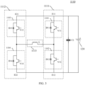
- the first sub-leg 1101 may include a first tube switch V11 and a first freewheeling diode D 11 connected in parallel to the first tube switch V11;
- the second sub-leg 1102 may include a second tube switch V12 and a second freewheeling diode D12 connected in parallel to the second tube switch V12;
- the third sub-leg 1103 may include a third tube switch V13 and a third freewheeling diode D13 connected in parallel to the third tube switch V13;
- the fourth sub-leg 1104 may include a fourth tube switch V14 and a fourth freewheeling diode D14 connected in parallel to the fourth tube switch V14.
- Freewheeling diodes are typically used together with inductors. An abrupt change of current flowing through the inductor leads to an abrupt change of voltage between two terminals of the inductor, which is likely to damage other elements in the circuit loop. When the inductor cooperates with a freewheeling diode, the current flowing through the inductor can change smoothly, which avoids the abrupt change of voltage, thereby improving safety of the circuit.
- the first tube switch V11 and first freewheeling diode D11 connected in parallel to the first tube switch V11, the second tube switch V12 and the second freewheeling diode D12 connected in parallel to the second tube switch V12, the third tube switch V13 and the third freewheeling diode D13 connected in parallel to the third tube switch V13, and the fourth tube switch V14 and the fourth freewheeling diode D14 connected in parallel to the fourth tube switch V14 may all be referred to as an insulated gate bipolar translator (Insulated Gate Bipolar Translator, IGBT).
- IGBT Insulated Gate Bipolar Translator
- the control module 1120 (not shown in FIG. 3 ) is specifically configured to: control the first tube switch V11 and the fourth tube switch V 14 to turn on and the second tube switch V12 and the third tube switch V13 to turn off, so as to form a loop including the traction battery 120, the first tube switch V11, the inductor L, and the fourth tube switch V14 for the traction battery 120 to discharge to the inductor L; and control the first tube switch V11, the second tube switch V12, the third tube switch V13, and the fourth tube switch V14 to turn off, so as to form a loop including the traction battery 120, the second freewheeling diode D12, the inductor L, and the third freewheeling diode D13 for the inductor L to charge the traction battery 120.
- each heating period may include a first stage and a second stage.
- the first tube switch V11 and the fourth tube switch V14 turn on and the second tube switch V12 and the third tube switch V13 turn off, that is, the first sub-leg 1101 and the fourth sub-leg 1104 turn on simultaneously, so as to form a loop including the traction battery 120, the first tube switch V11, the inductor L, and the fourth tube switch V14, where the loop is used by the traction battery 120 to discharge to the inductor L, and a discharge path is as follows: positive electrode of the battery ⁇ V11 ⁇ L ⁇ V14 ⁇ negative electrode of the battery.
- the first tube switch V11 and the fourth tube switch V14 also turn off to form a loop including the traction battery 120, the second freewheeling diode D12, the inductor L, and the third freewheeling diode D13, where the loop is used by the inductor L to charge the traction battery 120, and a charge path is as follows: negative electrode of the battery ⁇ D12 ⁇ L ⁇ D13 ⁇ positive electrode of the battery.
- control electric module 1120 is further configured to: control the second tube switch V12 and the third tube switch V13 to turn on and the first tube switch V11 and the fourth tube switch V14 to turn off, so as to form a loop including the traction battery 120, the third tube switch V13, the inductor L, and the second tube switch V12 for the traction battery 120 to discharge to the inductor L; and control the first tube switch V11, the second tube switch V12, the third tube switch V13, and the fourth tube switch V14 to turn off, so as to form a loop including the traction battery 120, the fourth freewheeling diode D14, the inductor L, and the first freewheeling diode D11 for the inductor L to charge the traction battery 120.
- each heating period may include a first stage and a second stage, or may include a third stage and a fourth stage, or may include all of a first stage, a second stage, a third stage, and a fourth stage.
- the second tube switch V12 and the third tube switch V13 turn on and the first tube switch V11 and the fourth tube switch V14 turn off, that is, the second sub-leg 1102 and the third sub-leg 1103 turn on simultaneously, so as to form a loop including the traction battery 120, the third tube switch V13, the inductor L, and the second tube switch V12, where the loop is used by the traction battery 120 to discharge to the inductor L, and a discharge path is as follows: positive electrode of the battery ⁇ V13 ⁇ L ⁇ V12 ⁇ negative electrode of the battery.
- the second tube switch V12 and the third tube switch V13 also turn off to form a loop including the traction battery 120, the fourth freewheeling diode D14, the inductor L, and the first freewheeling diode D11, where the loop is used by the inductor L to charge the traction battery 120, and a charge path is as follows: negative electrode of the battery ⁇ D14 ⁇ L ⁇ D11 ⁇ positive electrode of the battery.
- proper control timing is designed to control the sub-legs to turn on or off, so as to form the loop via which the traction battery 120 discharges to the inductor L and the loop via which the inductor L charges the traction battery 120.
- the discharge loop and the charge loop switch back and forth, so as to perform charge and discharge repeatedly between the traction battery 120 and the inductor L, thereby persistently heating the battery.
- the foregoing describes the process of heating the traction battery 120 by the battery heating apparatus 110 in this application, that is, a heating mode of the battery heating apparatus 110.
- the motor can operate as normal when the battery heating apparatus 110 heats the traction battery 120. Therefore, when the battery heating apparatus operates in the heating mode, normal driving of a vehicle with the traction battery 120 is not affected.
- the following describes, with reference to FIG. 4 , a process of a charging apparatus 140 charging the traction battery 120 via the battery heating apparatus 110, that is, a charge mode of the battery heating apparatus 110.
- the charging apparatus 140 includes but is not limited to a charging pile or a charger.
- the battery heating apparatus 110 is connected to the charging apparatus 140, and the charging apparatus 140 is configured to charge the traction battery 120 via the battery heating apparatus 110.
- the battery heating apparatus 110 has both a heating mode and a charge mode, and therefore, the battery heating apparatus 110 can not only be used for heating the traction battery 120, but also adjust charging voltage when the charging apparatus 140 charges the traction battery 120. In this way, when voltage of the charging apparatus 140 does not match voltage of the traction battery 120, for example, when the voltage of the charging apparatus 140 is lower than or higher than the voltage of the traction battery 120, the charging apparatus 140 can charge the traction battery 120 at a boosted voltage or at a stepped-down voltage via the battery heating apparatus 110, so as to improve adaptability between the charging apparatus 140 and the traction battery 120.
- the control module 1120 controls the first leg 1111 and the second leg 1112 to form a loop via which the charging apparatus 140 charges the energy storage element 1113 and a loop via which the charging apparatus 140 and the energy storage element 1113 charge the traction battery 120 simultaneously.
- the control module 1120 controls the first leg 1111 and the second leg 1112 to form a loop via which the charging apparatus 140 charges the traction battery 120 and the energy storage element 1113 and a loop via which the energy storage element 1113 charges the traction battery 120.
- a second terminal of the energy storage element 1113 is connected to one terminal of the charging apparatus 140 through a fifth tube switch V15; the second terminal E22 of the second leg 1112 is connected to another terminal of the charging apparatus 140; and the charging apparatus 140 is configured to charge the traction battery 120 via the battery heating apparatus 110.
- a capacitor C3 in FIG. 4 may be a capacitor of the charging apparatus 140, and can have, for example, a voltage stabilization function during charge.
- the third tube switch V13 may alternatively be used as a mode switching switch.
- the control module 1120 controls the third tube switch V13 to turn on; and when the battery heating apparatus 110 is in the charge mode, the control module 1120 controls the third tube switch V13 to turn off.
- the freewheeling diode D13 should not be connected to two terminals of the third tube switch V13.
- one heating period may include only the third stage and the fourth stage, that is, firstly, the second tube switch V12 and the third tube switch V13 turn on simultaneously to form a loop including the traction battery 120, the third tube switch V13, the inductor L, and the second tube switch V12 for the traction battery 120 to discharge to the inductor L; and secondly, the second tube switch V12 and the third tube switch V13 also turn off to form a loop including the traction battery 120, the fourth freewheeling diode D14, the inductor L, and the first freewheeling diode D 11 for the inductor L to charge the traction battery 120.
- the freewheeling diode D14 may alternatively not be connected to two terminals of the fourth tube switch V14.
- a sixth switch V16 may be connected between the first terminal E11 of the first leg 1111 and the first terminal E21 of the second leg 1112 to serve as a mode switching switch. In a heating mode, the sixth switch V16 turns on, and in a charge mode, the sixth switch V16 turns off.
- the control module 1120 is further configured to: control the third sub-leg 1103, for example, the third tube switch V13 or the sixth tube switch V 16, to turn off; when the voltage of the charging apparatus 140 is lower than the voltage of the traction battery 120, control the second tube switch V12 and the fifth tube switch V15 to turn on and the first tube switch V11 and the fourth tube switch V14 to turn off, so as to form a loop including the charging apparatus 140, the energy storage element 1113, and the second tube switch V12 for the charging apparatus 140 to charge the energy storage element 1113; and control the first tube switch V11 and the fifth tube switch V15 to turn on and the second tube switch V12 and the fourth tube switch V14 to turn off, so as to form a loop including the charging apparatus 140, the energy storage element 1113, the first tube switch V11, and the traction battery 120 for the charging apparatus 140 and the energy storage element 1113 to charge the traction battery 120 simultaneously.
- control module 1120 is further configured to: when the voltage of the charging apparatus 140 is higher than the voltage of the traction battery 120, control the first tube switch V11 and the fifth tube switch V15 to turn on and the second tube switch V12 and the fourth tube switch V14 to turn off, so as to form a loop including the charging apparatus 140, the energy storage element 1113, the first tube switch V11, and the traction battery 120 for the charging apparatus 140 to charge the traction battery 120 and the energy storage element 1113; and control the first tube switch V11 to turn on and the second tube switch V12, the fourth tube switch V14, and the fifth tube switch V15 to turn off, so as to form a loop including the energy storage element 1113, the first tube switch V11, the traction battery 120, and the fourth freewheeling diode D14 for the energy storage element 1113 to charge the traction battery 120.
- the charging apparatus 14 and the energy storage element 1113 can alternately charge the traction battery 120.
- the charging apparatus 140 charges the energy storage element 1113 and the traction battery 120
- the energy storage element 1113 can store a specific amount of power. Therefore, based on this amount of power, the energy storage element 1113 can charge the traction battery 120 alone.
- the traction battery 120 is further connected to a drive circuit 131 of a motor and configured to supply power to the drive circuit 131.
- the drive circuit 131 of the three-phase motor is an inverter circuit, including a leg formed by a tube switch V1, a tube switch V2, a tube switch V3, a tube switch V4, a tube switch V5, and a tube switch V6 and is connected to a winding A1, a winding B 1, and a winding C1 of a motor 130.
- the battery heating apparatus 110 when configured to heat the traction battery 120, the traction battery 120 still can supply power to the drive circuit 131 of the motor connected to the traction battery 120, so as to heat the traction battery 120 in driving.
- an additional battery heating apparatus 110 is provided, so that when the battery heating apparatus 110 is configured to heat the traction battery 120, a motor can drive a vehicle to run as normal, thereby implementing heating in driving.
- proper control timing is designed to control the legs in the battery heating apparatus 110, so as to form a loop via which the traction battery 120 discharges to the energy storage element 1113 in the battery heating apparatus 110 and a loop via which the energy storage element 1113 charges the traction battery 120, thereby heating the traction battery by effectively using the energy storage element 1113.
- the battery heating apparatus 110 When the charging apparatus 140 charges the traction battery 120 via the battery heating apparatus 110, the battery heating apparatus 110 enters the charge mode. In this case, because the battery heating apparatus 110 cannot be used for heating the traction battery 120, the drive circuit 131 of the motor can be used for heating the traction battery 120. Different from a method of heating the cooling liquid by using the heat produced due to operation loss of the motor, in this case, IGBTs in the drive circuit 131 can be controlled to form a charge/discharge loop, so as to heat the traction battery 120.
- the VCU can inform the motor control unit to control the drive circuit 131 of the motor to heat the traction battery 120, for example, control the IGBTs including the tube switches V1 to V6 in the drive circuit 131 to heat the traction battery 120 via the drive circuit 131.
- the battery heating apparatus 110 may also have another mode, that is, a charging and heating mode.
- a charging and heating mode When the battery heating apparatus 110 is in the charging and heating mode, the charging apparatus 140 charges the traction 120 via the battery heating apparatus 110, and the drive circuit 131 of the motor can heat the traction battery 120.
- a space vector pulse width modulation (Space Vector Pulse Width Modulation, SVPWM) method can be used for generating a control signal for tube switches of legs in the drive circuit 131, and the control signal is used for controlling an on/off state of the tube switches of the legs, so that a current flowing into a motor winding is modulated into an alternating current.
- a direct axis current component of the winding current can be controlled to be an alternating current
- a quadrature axis current component of the winding current is controlled to be 0, so as to modulate the current of the motor winding into the alternating current.
- Any two phase currents ia and ib collected by a three-phase connection circuit between the drive circuit 131 and the motor are obtained. Any two phase currents ia and ib flow from the drive circuit 131 to the motor.
- the motor control unit converts the collected current from an abc coordinate system to a dq coordinate system, and then decomposes the collected current in the dq coordinate system to obtain a direct axis component id and a quadrature axis component iq.
- the quadrature axis component iq, the direct axis component id, a quadrature axis signal given value i_q ⁇ ⁇ , and a direct axis signal given value i_d ⁇ ⁇ are used for obtaining a modulation signal of a tube switch that needs to turn on.
- the quadrature axis signal given value i_q ⁇ ⁇ is equal to 0. In this way, energy stored in the motor winding can be used for implementing charge/discharge the traction battery 120.
- Voltage fluctuation is caused in a process of heating the traction battery 120 by using the drive circuit 131 of the motor.
- the charging apparatus 140 outputs voltage to the traction battery 120 via the battery heating apparatus 110, so that dynamic regulation can be implemented with the voltage fluctuations in the battery heating process, thereby reducing impact of the battery heating process on the charging apparatus 140.
- connection in the embodiments of this application may be a direct connection or an indirect connection. This is not limited in this application.
- a connection between the first terminal E11 of the first leg 1111 and the first terminal E21 of the second leg 1112 may be, for example, a directly electrical connection between the first terminal E11 of the first leg 1111 and the first terminal E21 of the second leg 1112 shown in FIG. 3 , or may alternatively be a connection between the first terminal E11 of the first leg 1111 and the first terminal E21 of the second leg 1112 via another element, for example, the tube switch V16 shown in FIG. 5 .
- a control method 700 of battery heating apparatus includes either or both of the following steps.
- Step 710 Control the first leg and the second leg to form a loop via which the traction battery discharges to the energy storage element, so as to heat the traction battery during discharge.
- Step 720 Form a loop via which the energy storage element charges the traction battery to heat the traction battery during charge.
- proper control timing is designed to control two legs in the battery heating apparatus, so as to form a loop via which the traction battery discharges to the energy storage element and a loop via which the energy storage element charges the traction battery, thereby heating the traction battery during discharge and charge.
- a motor can drive a vehicle to run as normal, thereby implementing heating in driving.
- the battery heating apparatus is further connected to a charging apparatus, and the charging apparatus is configured to charge the traction battery via the battery heating apparatus.
- the control method further includes: when voltage of the charging apparatus is lower than voltage of the traction battery, controlling the first leg and the second leg to form a loop via which the charging apparatus charges the energy storage element and a loop via which the charging apparatus and the energy storage element charge the traction battery simultaneously; or when voltage of the charging apparatus is higher than voltage of the traction battery, controlling the first leg and the second leg to form a loop via which the charging apparatus charges the traction battery and the energy storage element and a loop via which the energy storage element charges the traction battery.
- a first terminal of the first leg, a first terminal of the second leg, and a first terminal of the traction battery are connected; and a second terminal of the first leg, a second terminal of the second leg, and a second terminal of the traction battery are connected.
- the first leg includes a first sub-leg and a second sub-leg, and the second leg includes a third sub-leg and a fourth sub-leg.
- a first terminal of the energy storage element is connected between the first sub-leg and the second sub-leg, and a second terminal of the energy storage element is connected between the third sub-leg and the fourth sub-leg.
- the first sub-leg includes a first tube switch and a first freewheeling diode connected in parallel to the first tube switch;
- the second sub-leg includes a second tube switch and a second freewheeling diode connected in parallel to the second tube switch;
- the third sub-leg includes a third tube switch and a third freewheeling diode connected in parallel to the third tube switch;
- the fourth sub-leg includes a fourth tube switch and a fourth freewheeling diode connected in parallel to the fourth tube switch.
- controlling the first leg, the second leg, and the traction battery includes: receiving a heating request message; and generating a first control signal according to the heating request message, where the first control signal is used to:
- control method further includes: receiving a heating stopping message; and generating a second control signal according to the heating stopping message, where the second control signal is used to control the battery heating apparatus to stop heating the traction battery.
- the second terminal of the energy storage element is connected to one terminal of the charging apparatus through a fifth tube switch
- the second terminal of the second leg is connected to another terminal of the charging apparatus
- the charging apparatus is configured to charge the traction battery via the heating module.
- the controlling the first leg, the second leg, and the traction battery further includes: controlling the third sub-leg to turn off; when voltage of the charging apparatus is lower than voltage of the traction battery, controlling the second tube switch and the fifth tube switch to turn on and the first tube switch and the fourth tube switch to turn off, so as to form a loop that includes the charging apparatus, the energy storage element, and the second tube switch and that is used by the charging apparatus to charge the energy storage element; and controlling the first tube switch and the fifth tube switch to turn on and the second tube switch and the fourth tube switch to turn off, so as to form a loop that includes the charging apparatus, the energy storage element, the first tube switch, and the traction battery and that is used by the charging apparatus and the energy storage element to charge the traction battery simultaneously.
- controlling the first leg, the second leg, and the traction battery further includes: when voltage of the charging apparatus is higher than voltage of the traction battery, controlling the first tube switch and the fifth tube switch to turn on and the second tube switch and the fourth tube switch to turn off, so as to form a loop that includes the charging apparatus, the energy storage element, the first tube switch, and the traction battery and that is used by the charging apparatus to charge the traction battery and the energy storage element; and controlling the first tube switch to turn on and the second tube switch, the fourth tube switch, and the fifth tube switch to turn off, so as to form a loop that includes the energy storage element, the first tube switch, the traction battery, and the fourth freewheeling diode and that is used by the energy storage element to charge the traction battery.
- the energy storage element includes an inductor; or the energy storage element includes an inductor and a first capacitor connected in series.
- a second capacitor is further connected in parallel to two terminals of the traction battery.
- the traction battery is further connected to a drive circuit of a motor and configured to supply power to the drive circuit.
- FIG. 8 is a schematic block diagram of a control circuit 800 of battery heating apparatus according to an embodiment of this application.
- the control circuit 800 includes a processor 820; optionally, the control circuit 800 further includes a memory 810, where the memory 810 is configured to store instructions; and the processor 820 is configured to read the instructions and perform the method in the foregoing embodiments of this application based on the instructions.
- the processor 820 may correspond to the control module of any one of the foregoing battery heating apparatuses.
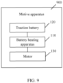
- FIG. 9 is a schematic block diagram of a motive apparatus 900 according to an embodiment of this application.
- the motive apparatus 900 includes: a traction battery 120; the battery heating apparatus 110 in any one of the foregoing embodiments, where the battery heating apparatus 110 is connected to the traction battery 120 and configured to heat the traction battery 120; and a motor 130, where a drive circuit 131 of the motor 130 is connected to the traction battery 120, and the traction battery 120 is configured to supply power to the drive circuit 131.
- the motive apparatus 900 may be a motorized vehicle.
- An embodiment of this application further provides a readable storage medium, where the readable storage medium is configured to store a computer program, and the computer program is used to perform the method in the foregoing embodiments of this application.
- the disclosed system, apparatus, and method may be implemented in other manners.
- the described apparatus embodiments are merely illustrative.
- the unit division is merely logical function division and other division manners may be used in actual implementation.
- a plurality of units or components may be combined or integrated into another system, or some features may be ignored or not be performed.
- the displayed or discussed mutual couplings, direct couplings or communication connections may be indirect couplings or communication connections through some interfaces, apparatuses or units, and may be in electrical, mechanical, or other forms.
- the units described as separate parts may or may not be physically separated. Parts displayed as units may or may not be physical units, meaning they may be located in one position or distributed on a plurality of network units. Some or all of the units may be selected depending on actual requirements to achieve the objectives of the solutions of the embodiments.
- function units in the embodiments of this application may be integrated into one processing unit, or each of the units may exist alone physically, or two or more units may be integrated into one unit.
- the function When realized in form of software functional unit and sold or used as an independent product, the function may also be stored in a computer-readable storage medium.
- the computer software product is stored in a storage medium and includes a plurality of instructions used to enable a computer device which may be, for example, a personal computer, a server, or a network device to perform all or some of the steps of the method in the embodiments of the application.
- the foregoing storage medium includes various media capable of storing program code, such as a USB flash drive, a removable hard disk, a read-only memory (Read-Only Memory, ROM), a random access memory (Random Access Memory, RAM), a magnetic disk, or an optical disc.
- program code such as a USB flash drive, a removable hard disk, a read-only memory (Read-Only Memory, ROM), a random access memory (Random Access Memory, RAM), a magnetic disk, or an optical disc.
Landscapes
- Engineering & Computer Science (AREA)
- Manufacturing & Machinery (AREA)
- Chemical & Material Sciences (AREA)
- Chemical Kinetics & Catalysis (AREA)
- Electrochemistry (AREA)
- General Chemical & Material Sciences (AREA)
- Power Engineering (AREA)
- Transportation (AREA)
- Mechanical Engineering (AREA)
- Automation & Control Theory (AREA)
- Life Sciences & Earth Sciences (AREA)
- Sustainable Development (AREA)
- Sustainable Energy (AREA)
- Charge And Discharge Circuits For Batteries Or The Like (AREA)
- Secondary Cells (AREA)
- Inverter Devices (AREA)
Applications Claiming Priority (1)
| Application Number | Priority Date | Filing Date | Title |
|---|---|---|---|
| PCT/CN2021/116735 WO2023029047A1 (zh) | 2021-09-06 | 2021-09-06 | 电池加热装置及其控制方法、控制电路和动力装置 |
Publications (2)
| Publication Number | Publication Date |
|---|---|
| EP4250436A1 true EP4250436A1 (de) | 2023-09-27 |
| EP4250436A4 EP4250436A4 (de) | 2024-04-03 |
Family
ID=85411892
Family Applications (1)
| Application Number | Title | Priority Date | Filing Date |
|---|---|---|---|
| EP21955578.6A Pending EP4250436A4 (de) | 2021-09-06 | 2021-09-06 | Batterieheizvorrichtung und steuerungsverfahren, steuerschaltung und leistungsvorrichtung dafür |
Country Status (6)
| Country | Link |
|---|---|
| US (1) | US20230299374A1 (de) |
| EP (1) | EP4250436A4 (de) |
| JP (1) | JP7570590B2 (de) |
| KR (1) | KR20230107650A (de) |
| CN (1) | CN115956317B (de) |
| WO (1) | WO2023029047A1 (de) |
Families Citing this family (1)
| Publication number | Priority date | Publication date | Assignee | Title |
|---|---|---|---|---|
| CN119154469B (zh) * | 2024-09-29 | 2025-04-08 | 浙江巨江新能源科技有限责任公司 | 一种钠电池组低温充电限流电路、装置及控制方法 |
Family Cites Families (12)
| Publication number | Priority date | Publication date | Assignee | Title |
|---|---|---|---|---|
| JP2011188600A (ja) | 2010-03-08 | 2011-09-22 | Toyota Central R&D Labs Inc | 充電システム |
| CN106025443B (zh) * | 2016-07-25 | 2018-12-07 | 北京理工大学 | 一种基于lc谐振进行加热的电源系统及车辆 |
| CN107039708B (zh) | 2016-11-29 | 2019-08-02 | 北京交通大学 | 一种锂离子电池组低温自加热方法 |
| CN111347924B (zh) * | 2018-12-21 | 2022-09-09 | 比亚迪股份有限公司 | 电机控制电路、车辆、加热方法及充放电方法 |
| CN111347853B (zh) * | 2018-12-21 | 2022-01-07 | 比亚迪股份有限公司 | 电机控制电路、充放电方法、加热方法及车辆 |
| CN111347900B (zh) * | 2018-12-21 | 2021-11-12 | 比亚迪股份有限公司 | 一种车辆、电机控制电路、动力电池充电与加热方法 |
| CN109823234B (zh) * | 2019-04-23 | 2019-07-16 | 上海汽车集团股份有限公司 | 一种驱动系统的控制方法、驱动系统及新能源汽车 |
| JP7057767B2 (ja) | 2019-07-09 | 2022-04-20 | 株式会社Soken | 電源システム |
| CN110789400A (zh) * | 2019-10-22 | 2020-02-14 | 上海交通大学 | 电池无线充电-加热一体化系统、控制方法及电池系统 |
| CN212587580U (zh) | 2020-05-29 | 2021-02-23 | 比亚迪股份有限公司 | 电池能量处理装置和车辆 |
| CN111391717B (zh) * | 2020-06-04 | 2020-10-20 | 比亚迪股份有限公司 | 能量转换装置、方法及车辆 |
| CN213734669U (zh) * | 2020-08-05 | 2021-07-20 | 比亚迪股份有限公司 | 一种能量转换装置及车辆 |
-
2021
- 2021-09-06 WO PCT/CN2021/116735 patent/WO2023029047A1/zh not_active Ceased
- 2021-09-06 CN CN202180048180.9A patent/CN115956317B/zh active Active
- 2021-09-06 EP EP21955578.6A patent/EP4250436A4/de active Pending
- 2021-09-06 KR KR1020237019956A patent/KR20230107650A/ko active Pending
- 2021-09-06 JP JP2023535941A patent/JP7570590B2/ja active Active
-
2023
- 2023-05-24 US US18/322,897 patent/US20230299374A1/en active Pending
Also Published As
| Publication number | Publication date |
|---|---|
| CN115956317A (zh) | 2023-04-11 |
| JP2023553181A (ja) | 2023-12-20 |
| US20230299374A1 (en) | 2023-09-21 |
| WO2023029047A1 (zh) | 2023-03-09 |
| CN115956317B (zh) | 2024-01-05 |
| JP7570590B2 (ja) | 2024-10-22 |
| EP4250436A4 (de) | 2024-04-03 |
| KR20230107650A (ko) | 2023-07-17 |
Similar Documents
| Publication | Publication Date | Title |
|---|---|---|
| EP4369474A1 (de) | Lade- und entladeschaltung, system und steuerungsverfahren dafür | |
| EP4528970A1 (de) | Lade- und entladeschaltung für eine strombatterie sowie lade- und entladesystem für eine strombatterie und steuerungsverfahren und steuerungsvorrichtung dafür | |
| US20240154440A1 (en) | Charge-and-discharge circuit, charge-and-discharge system and charge-and-discharge control method | |
| US12227109B2 (en) | Power battery heating system and control method and control circuit thereof | |
| US12485800B2 (en) | Traction battery heating circuit, system, and control method, and electric device | |
| US20240363918A1 (en) | Control method of heating system for battery and heating system | |
| US20240235243A1 (en) | Power battery voltage regulation system and control method and control apparatus thereof | |
| US11901757B2 (en) | Electric vehicle battery voltage regulation system and control method and control apparatus therefor | |
| US20230299374A1 (en) | Battery heating apparatus, control method and control circuit thereof, and motive apparatus | |
| US12431556B2 (en) | Heating method and heating system of traction battery | |
| US20230411734A1 (en) | Battery heating device and control method and circuit therefor, and power device |
Legal Events
| Date | Code | Title | Description |
|---|---|---|---|
| STAA | Information on the status of an ep patent application or granted ep patent |
Free format text: STATUS: THE INTERNATIONAL PUBLICATION HAS BEEN MADE |
|
| PUAI | Public reference made under article 153(3) epc to a published international application that has entered the european phase |
Free format text: ORIGINAL CODE: 0009012 |
|
| STAA | Information on the status of an ep patent application or granted ep patent |
Free format text: STATUS: REQUEST FOR EXAMINATION WAS MADE |
|
| 17P | Request for examination filed |
Effective date: 20230622 |
|
| AK | Designated contracting states |
Kind code of ref document: A1 Designated state(s): AL AT BE BG CH CY CZ DE DK EE ES FI FR GB GR HR HU IE IS IT LI LT LU LV MC MK MT NL NO PL PT RO RS SE SI SK SM TR |
|
| A4 | Supplementary search report drawn up and despatched |
Effective date: 20240304 |
|
| RIC1 | Information provided on ipc code assigned before grant |
Ipc: H02M 3/158 20060101ALI20240227BHEP Ipc: H02J 7/34 20060101ALI20240227BHEP Ipc: H02J 7/04 20060101ALI20240227BHEP Ipc: H02J 7/00 20060101ALI20240227BHEP Ipc: B60L 58/10 20190101ALI20240227BHEP Ipc: B60L 58/27 20190101ALI20240227BHEP Ipc: H01M 10/625 20140101ALI20240227BHEP Ipc: H01M 10/615 20140101AFI20240227BHEP |
|
| RAP1 | Party data changed (applicant data changed or rights of an application transferred) |
Owner name: CONTEMPORARY AMPEREX TECHNOLOGY(HONG KONG) LIMITED |
|
| DAV | Request for validation of the european patent (deleted) | ||
| DAX | Request for extension of the european patent (deleted) |