EP4250351A1 - Heatsink, active energy irradiation device, and active energy irradiation system - Google Patents
Heatsink, active energy irradiation device, and active energy irradiation system Download PDFInfo
- Publication number
- EP4250351A1 EP4250351A1 EP21909757.3A EP21909757A EP4250351A1 EP 4250351 A1 EP4250351 A1 EP 4250351A1 EP 21909757 A EP21909757 A EP 21909757A EP 4250351 A1 EP4250351 A1 EP 4250351A1
- Authority
- EP
- European Patent Office
- Prior art keywords
- heatsink
- base plate
- radiation fins
- heat radiation
- active energy
- Prior art date
- Legal status (The legal status is an assumption and is not a legal conclusion. Google has not performed a legal analysis and makes no representation as to the accuracy of the status listed.)
- Pending
Links
Images







Classifications
-
- H—ELECTRICITY
- H10—SEMICONDUCTOR DEVICES; ELECTRIC SOLID-STATE DEVICES NOT OTHERWISE PROVIDED FOR
- H10W—GENERIC PACKAGES, INTERCONNECTIONS, CONNECTORS OR OTHER CONSTRUCTIONAL DETAILS OF DEVICES COVERED BY CLASS H10
- H10W40/00—Arrangements for thermal protection or thermal control
- H10W40/40—Arrangements for thermal protection or thermal control involving heat exchange by flowing fluids
- H10W40/43—Arrangements for thermal protection or thermal control involving heat exchange by flowing fluids by flowing gases, e.g. forced air cooling
-
- H—ELECTRICITY
- H10—SEMICONDUCTOR DEVICES; ELECTRIC SOLID-STATE DEVICES NOT OTHERWISE PROVIDED FOR
- H10W—GENERIC PACKAGES, INTERCONNECTIONS, CONNECTORS OR OTHER CONSTRUCTIONAL DETAILS OF DEVICES COVERED BY CLASS H10
- H10W40/00—Arrangements for thermal protection or thermal control
- H10W40/10—Arrangements for heating
-
- F—MECHANICAL ENGINEERING; LIGHTING; HEATING; WEAPONS; BLASTING
- F21—LIGHTING
- F21V—FUNCTIONAL FEATURES OR DETAILS OF LIGHTING DEVICES OR SYSTEMS THEREOF; STRUCTURAL COMBINATIONS OF LIGHTING DEVICES WITH OTHER ARTICLES, NOT OTHERWISE PROVIDED FOR
- F21V29/00—Protecting lighting devices from thermal damage; Cooling or heating arrangements specially adapted for lighting devices or systems
- F21V29/50—Cooling arrangements
- F21V29/60—Cooling arrangements characterised by the use of a forced flow of gas, e.g. air
-
- F—MECHANICAL ENGINEERING; LIGHTING; HEATING; WEAPONS; BLASTING
- F21—LIGHTING
- F21V—FUNCTIONAL FEATURES OR DETAILS OF LIGHTING DEVICES OR SYSTEMS THEREOF; STRUCTURAL COMBINATIONS OF LIGHTING DEVICES WITH OTHER ARTICLES, NOT OTHERWISE PROVIDED FOR
- F21V29/00—Protecting lighting devices from thermal damage; Cooling or heating arrangements specially adapted for lighting devices or systems
- F21V29/50—Cooling arrangements
- F21V29/70—Cooling arrangements characterised by passive heat-dissipating elements, e.g. heat-sinks
- F21V29/71—Cooling arrangements characterised by passive heat-dissipating elements, e.g. heat-sinks using a combination of separate elements interconnected by heat-conducting means, e.g. with heat pipes or thermally conductive bars between separate heat-sink elements
- F21V29/713—Cooling arrangements characterised by passive heat-dissipating elements, e.g. heat-sinks using a combination of separate elements interconnected by heat-conducting means, e.g. with heat pipes or thermally conductive bars between separate heat-sink elements in direct thermal and mechanical contact of each other to form a single system
-
- F—MECHANICAL ENGINEERING; LIGHTING; HEATING; WEAPONS; BLASTING
- F21—LIGHTING
- F21V—FUNCTIONAL FEATURES OR DETAILS OF LIGHTING DEVICES OR SYSTEMS THEREOF; STRUCTURAL COMBINATIONS OF LIGHTING DEVICES WITH OTHER ARTICLES, NOT OTHERWISE PROVIDED FOR
- F21V29/00—Protecting lighting devices from thermal damage; Cooling or heating arrangements specially adapted for lighting devices or systems
- F21V29/50—Cooling arrangements
- F21V29/70—Cooling arrangements characterised by passive heat-dissipating elements, e.g. heat-sinks
- F21V29/74—Cooling arrangements characterised by passive heat-dissipating elements, e.g. heat-sinks with fins or blades
- F21V29/76—Cooling arrangements characterised by passive heat-dissipating elements, e.g. heat-sinks with fins or blades with essentially identical parallel planar fins or blades, e.g. with comb-like cross-section
-
- F—MECHANICAL ENGINEERING; LIGHTING; HEATING; WEAPONS; BLASTING
- F21—LIGHTING
- F21V—FUNCTIONAL FEATURES OR DETAILS OF LIGHTING DEVICES OR SYSTEMS THEREOF; STRUCTURAL COMBINATIONS OF LIGHTING DEVICES WITH OTHER ARTICLES, NOT OTHERWISE PROVIDED FOR
- F21V29/00—Protecting lighting devices from thermal damage; Cooling or heating arrangements specially adapted for lighting devices or systems
- F21V29/50—Cooling arrangements
- F21V29/70—Cooling arrangements characterised by passive heat-dissipating elements, e.g. heat-sinks
- F21V29/83—Cooling arrangements characterised by passive heat-dissipating elements, e.g. heat-sinks the elements having apertures, ducts or channels, e.g. heat radiation holes
-
- F—MECHANICAL ENGINEERING; LIGHTING; HEATING; WEAPONS; BLASTING
- F28—HEAT EXCHANGE IN GENERAL
- F28D—HEAT-EXCHANGE APPARATUS, NOT PROVIDED FOR IN ANOTHER SUBCLASS, IN WHICH THE HEAT-EXCHANGE MEDIA DO NOT COME INTO DIRECT CONTACT
- F28D15/00—Heat-exchange apparatus with the intermediate heat-transfer medium in closed tubes passing into or through the conduit walls ; Heat-exchange apparatus employing intermediate heat-transfer medium or bodies
- F28D15/02—Heat-exchange apparatus with the intermediate heat-transfer medium in closed tubes passing into or through the conduit walls ; Heat-exchange apparatus employing intermediate heat-transfer medium or bodies in which the medium condenses and evaporates, e.g. heat pipes
- F28D15/0275—Arrangements for coupling heat-pipes together or with other structures, e.g. with base blocks; Heat pipe cores
-
- F—MECHANICAL ENGINEERING; LIGHTING; HEATING; WEAPONS; BLASTING
- F28—HEAT EXCHANGE IN GENERAL
- F28F—DETAILS OF HEAT-EXCHANGE AND HEAT-TRANSFER APPARATUS, OF GENERAL APPLICATION
- F28F1/00—Tubular elements; Assemblies of tubular elements
- F28F1/10—Tubular elements and assemblies thereof with means for increasing heat-transfer area, e.g. with fins, with projections, with recesses
- F28F1/12—Tubular elements and assemblies thereof with means for increasing heat-transfer area, e.g. with fins, with projections, with recesses the means being only outside the tubular element
- F28F1/24—Tubular elements and assemblies thereof with means for increasing heat-transfer area, e.g. with fins, with projections, with recesses the means being only outside the tubular element and extending transversely
- F28F1/32—Tubular elements and assemblies thereof with means for increasing heat-transfer area, e.g. with fins, with projections, with recesses the means being only outside the tubular element and extending transversely the means having portions engaging further tubular elements
-
- F—MECHANICAL ENGINEERING; LIGHTING; HEATING; WEAPONS; BLASTING
- F28—HEAT EXCHANGE IN GENERAL
- F28F—DETAILS OF HEAT-EXCHANGE AND HEAT-TRANSFER APPARATUS, OF GENERAL APPLICATION
- F28F13/00—Arrangements for modifying heat-transfer, e.g. increasing, decreasing
- F28F13/06—Arrangements for modifying heat-transfer, e.g. increasing, decreasing by affecting the pattern of flow of the heat-exchange media
-
- H—ELECTRICITY
- H05—ELECTRIC TECHNIQUES NOT OTHERWISE PROVIDED FOR
- H05K—PRINTED CIRCUITS; CASINGS OR CONSTRUCTIONAL DETAILS OF ELECTRIC APPARATUS; MANUFACTURE OF ASSEMBLAGES OF ELECTRICAL COMPONENTS
- H05K7/00—Constructional details common to different types of electric apparatus
- H05K7/20—Modifications to facilitate cooling, ventilating, or heating
-
- H—ELECTRICITY
- H10—SEMICONDUCTOR DEVICES; ELECTRIC SOLID-STATE DEVICES NOT OTHERWISE PROVIDED FOR
- H10W—GENERIC PACKAGES, INTERCONNECTIONS, CONNECTORS OR OTHER CONSTRUCTIONAL DETAILS OF DEVICES COVERED BY CLASS H10
- H10W40/00—Arrangements for thermal protection or thermal control
- H10W40/70—Fillings or auxiliary members in containers or in encapsulations for thermal protection or control
- H10W40/73—Fillings or auxiliary members in containers or in encapsulations for thermal protection or control for cooling by change of state
-
- F—MECHANICAL ENGINEERING; LIGHTING; HEATING; WEAPONS; BLASTING
- F21—LIGHTING
- F21Y—INDEXING SCHEME ASSOCIATED WITH SUBCLASSES F21K, F21L, F21S and F21V, RELATING TO THE FORM OR THE KIND OF THE LIGHT SOURCES OR OF THE COLOUR OF THE LIGHT EMITTED
- F21Y2115/00—Light-generating elements of semiconductor light sources
- F21Y2115/10—Light-emitting diodes [LED]
-
- F—MECHANICAL ENGINEERING; LIGHTING; HEATING; WEAPONS; BLASTING
- F28—HEAT EXCHANGE IN GENERAL
- F28D—HEAT-EXCHANGE APPARATUS, NOT PROVIDED FOR IN ANOTHER SUBCLASS, IN WHICH THE HEAT-EXCHANGE MEDIA DO NOT COME INTO DIRECT CONTACT
- F28D15/00—Heat-exchange apparatus with the intermediate heat-transfer medium in closed tubes passing into or through the conduit walls ; Heat-exchange apparatus employing intermediate heat-transfer medium or bodies
- F28D15/02—Heat-exchange apparatus with the intermediate heat-transfer medium in closed tubes passing into or through the conduit walls ; Heat-exchange apparatus employing intermediate heat-transfer medium or bodies in which the medium condenses and evaporates, e.g. heat pipes
- F28D15/0233—Heat-exchange apparatus with the intermediate heat-transfer medium in closed tubes passing into or through the conduit walls ; Heat-exchange apparatus employing intermediate heat-transfer medium or bodies in which the medium condenses and evaporates, e.g. heat pipes the conduits having a particular shape, e.g. non-circular cross-section, annular
-
- F—MECHANICAL ENGINEERING; LIGHTING; HEATING; WEAPONS; BLASTING
- F28—HEAT EXCHANGE IN GENERAL
- F28D—HEAT-EXCHANGE APPARATUS, NOT PROVIDED FOR IN ANOTHER SUBCLASS, IN WHICH THE HEAT-EXCHANGE MEDIA DO NOT COME INTO DIRECT CONTACT
- F28D21/00—Heat-exchange apparatus not covered by any of the groups F28D1/00 - F28D20/00
- F28D2021/0019—Other heat exchangers for particular applications; Heat exchange systems not otherwise provided for
- F28D2021/0028—Other heat exchangers for particular applications; Heat exchange systems not otherwise provided for for cooling heat generating elements, e.g. for cooling electronic components or electric devices
- F28D2021/0029—Heat sinks
-
- F—MECHANICAL ENGINEERING; LIGHTING; HEATING; WEAPONS; BLASTING
- F28—HEAT EXCHANGE IN GENERAL
- F28F—DETAILS OF HEAT-EXCHANGE AND HEAT-TRANSFER APPARATUS, OF GENERAL APPLICATION
- F28F2215/00—Fins
-
- F—MECHANICAL ENGINEERING; LIGHTING; HEATING; WEAPONS; BLASTING
- F28—HEAT EXCHANGE IN GENERAL
- F28F—DETAILS OF HEAT-EXCHANGE AND HEAT-TRANSFER APPARATUS, OF GENERAL APPLICATION
- F28F2250/00—Arrangements for modifying the flow of the heat exchange media, e.g. flow guiding means; Particular flow patterns
- F28F2250/08—Fluid driving means, e.g. pumps, fans
Definitions
- the present disclosure relates to a heatsink, an active energy irradiation device, and an active energy irradiation system.
- a heatsink has been known that includes a base plate thermally connected to a heat-generating unit, and a plurality of heat radiation fins erected on a surface of the base plate, and arranged with gaps in a first direction along the surface (for example, refer to Patent Literature 1).
- Patent Literature 1 Japanese Unexamined Patent Publication No. 2001-118972
- An object of the present disclosure is to provide a heatsink, an active energy irradiation device, and an active energy irradiation system capable of enhancing cooling efficiency.
- a heatsink including: a base plate thermally connected to a heat-generating unit; a plurality of heat radiation fins erected on a surface of the base plate, and arranged with gaps in a first direction along the surface; and a partition member provided to intersect the plurality of heat radiation fins, and partitioning the plurality of heat radiation fins in a second direction along the surface and intersecting the first direction.
- the partition member partitions the plurality of heat radiation fins such that more air passes through in the second direction between the plurality of heat radiation fins on a base plate side than on a side opposite to the base plate side.
- the air flows into the plurality of heat radiation fins from the side opposite to the base plate side, due to the presence of the partition member, the air flows to the base plate side between the plurality of heat radiation fins, and then flows in the second direction, turns, and flows to a side away from the base plate. Therefore, the air can effectively flow between the plurality of heat radiation fins, and the cooling efficiency can be enhanced.
- an end on the base plate side of the partition member may be spaced apart from the base plate.
- a space allowing the air to pass through can be created between the end on the base plate side of the partition member and the base plate.
- a configuration can be specifically realized in which more air passes through in the second direction between the plurality of heat radiation fins on the base plate side than on the side opposite to the base plate side.
- a ventilation portion allowing the air to pass through may be provided on the base plate side of the partition member.
- the ventilation portion can be used as a space through which the air passes.
- the configuration can be specifically realized in which more air passes through in the second direction between the plurality of heat radiation fins on the base plate side than on the side opposite to the base plate side.
- the partition member may include a mesh portion, and the base plate side of the mesh portion may have a larger opening ratio than an opening ratio of the side opposite to the base plate side in the mesh portion.
- the mesh portion can be used as a space through which the air passes
- the base plate side of the mesh portion can be used as a space through which more air passes.
- the configuration can be specifically realized in which more air passes through in the second direction between the plurality of heat radiation fins on the base plate side than on the side opposite to the base plate side.
- the partition member may be brazed to the plurality of heat radiation fins. Accordingly, the plurality of heat radiation fins and the partition member are thermally connected, so that heat of the plurality of heat radiation fins can be effectively diffused by the partition member.
- a slit that is open on the side opposite to the base plate side may be formed in the plurality of heat radiation fins, and the partition member may be interposed in the slit of the plurality of heat radiation fins.
- the partition member can be easily provided.
- the heatsink when viewed in the first direction, at least one of a pair of facing sides among sides forming the slit may be bent to enter an inside of the slit.
- inner surfaces of the slit act as a spring (caulking) due to the fact that the side is bent, and reliable contact between the partition member and the heat radiation fins is obtained, so that heat can be effectively transferred therebetween.
- a pair of the partition members may be provided spaced apart from each other.
- the pair of partition members can partition the plurality of heat radiation fins.
- the heatsink according to one aspect of the present disclosure may further include a heat pipe provided to be embedded in the plurality of heat radiation fins and thermally connected to the plurality of heat radiation fins. In this case, heat can be effectively radiated using the heat pipe.
- the heat pipe may include a pair of first heat pipes provided spaced apart from each other so as to be embedded in the plurality of heat radiation fins, and a pair of second heat pipes provided spaced apart from each other so as to be embedded between the pair of first heat pipes in the plurality of heat radiation fins, and longer than the first heat pipes.
- the partition members may be each provided between one first heat pipe and one second heat pipe adjacent to each other and between the other first heat pipe and the other second heat pipe adjacent to each other.
- the air flowing to the base plate side can come into contact with the first heat pipes, and then the air that turns and flows to a side away from the base plate can come into contact with the second heat pipes.
- the air flowing between the plurality of heat radiation fins can come into contact with the first heat pipes in a state where the temperature is still relatively low, and thereafter, in a state where the temperature has risen, the air can come into contact with the second heat pipes having a higher heat radiation capacity than that of the first heat pipes. Accordingly, heat can be uniformly radiated using the heat pipe.
- grooves that are open on the side opposite to the base plate side may be each formed in the plurality of heat radiation fins. In this case, other members can be engaged with the heat radiation fins using the groove.
- an active energy irradiation device including: the heatsink; a plurality of active energy irradiation units thermally connected to the base plate of the heatsink, and arranged at least along a predetermined direction; and a housing that houses the heatsink and the active energy irradiation units.
- a flow path allowing the air to flow into the gaps between the plurality of heat radiation fins from the side opposite to the base plate side may be provided inside the housing.
- the air that has flowed to the heatsink flows to the base plate side between the plurality of heat radiation fins, and then turns in the second direction, and flows to a side away from the base plate between the plurality of heat radiation fins. Therefore, the air can effectively flow between the plurality of heat radiation fins, and the cooling efficiency can be enhanced.
- an active energy irradiation device including: the heatsink; a plurality of active energy irradiation units thermally connected to the base plate of the heatsink, and arranged at least along a predetermined direction; and a housing that houses the heatsink and the active energy irradiation units.
- the pair of partition members of the heatsink partition the plurality of heat radiation fins of the heatsink into a pair of outer portions located outside in the predetermined direction and an inner portion located between the pair of outer portions.
- a flow path allowing the air to flow into the gaps between the plurality of heat radiation fins in the pair of outer portions from the side opposite to the base plate side is provided inside the housing.
- the air that has flowed into the plurality of heat radiation fins of the heatsink flows to the base plate side between the plurality of heat radiation fins in each of the pair of outer portions, and then turns in the second direction, merges, and flows to a side away from the base plate between the plurality of heat radiation fins in the inner portion. Therefore, the air can effectively flow between the plurality of heat radiation fins, and the cooling efficiency can be enhanced.
- an active energy irradiation device including: the heatsink; a plurality of active energy irradiation units thermally connected to the base plate of the heatsink, and arranged at least along a predetermined direction; a housing that houses the heatsink and the active energy irradiation units; an exhaust unit that is provided in the housing, and that discharges the air, which has passed through the heatsink, to an outside of the housing; and a duct provided between the heatsink and the exhaust unit inside the housing, and allowing the air, which has passed through the heatsink, to flow through to the exhaust unit.
- One end portion on the base plate side of the duct is inserted into the grooves.
- the air that has flowed into the plurality of heat radiation fins of the heatsink flows to the base plate side between the plurality of heat radiation fins in one of a first portion and a second portion, and then turns in the second direction, and flows to a side away from the base plate between the plurality of heat radiation fins in the other of the first portion and the second portion. Therefore, the air can effectively flow between the plurality of heat radiation fins, and the cooling efficiency can be enhanced.
- the duct can be engaged with the heat radiation fins using the groove, and the need for a seal member such as a packing at a connection between the duct and the heat radiation fins can be eliminated.
- the one end portion on the base plate side of the duct may be inserted into the grooves through a heat conductive material. In this case, heat can be effectively transferred from the plurality of heat radiation fins to the duct.
- the active energy irradiation units may perform irradiation with an ultraviolet ray or an electron beam. Accordingly, the active energy irradiation device can be used as a device that performs irradiation with an ultraviolet ray or an electron beam.
- an active energy irradiation system including: a plurality of the active energy irradiation devices.
- the plurality of active energy irradiation devices are arranged to be in contact with each other in the predetermined direction.
- the plurality of active energy irradiation devices When the plurality of active energy irradiation devices are arranged to be in contact with each other in the predetermined direction, in each of the active energy irradiation devices, due to the influence of other adjacent active energy irradiation devices, the plurality of active energy irradiation units are likely to become overheated (particularly, the plurality of active energy irradiation units are likely to become overheated that are located at both end portions in the predetermined direction among the plurality of active energy irradiation units).
- the active energy irradiation system includes the active energy irradiation system, the cooling efficiency can be enhanced, so that the overheating of the plurality of active energy irradiation units can be suppressed.
- the heatsink, the active energy irradiation device, and the active energy irradiation system capable of enhancing cooling efficiency.
- an active energy irradiation system 100 is, for example, a system that is installed in an ultraviolet (UV) printer, and includes a plurality of active energy irradiation devices 1.
- the active energy irradiation devices 1 are, for example, high-output air-cooled LED light sources for printing applications.
- the active energy irradiation devices 1 irradiate an irradiation target with light (ultraviolet rays, active energy rays) to dry ink on the irradiation target. Examples of the irradiation target include a printed matter to which a photocurable ink is adhered.
- the active energy irradiation devices 1 have a rectangular parallelepiped outer shape.
- the active energy irradiation devices 1 are arranged to be in contact with each other in a predetermined direction.
- the plurality of active energy irradiation devices 1 arranged in the predetermined direction are fixed and held by a fixing plate 11.
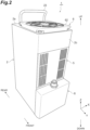
- the active energy irradiation device 1 includes a housing 2, a plurality of LED substrates 3, a heatsink 4, an intake unit 5, an exhaust unit 6, a duct 7, an inert gas supply unit 8, and an inert gas suction unit 9.
- the predetermined direction in which the plurality of active energy irradiation devices 1 are arranged is defined as an "X direction", a direction perpendicular to the X direction, which is a light emission direction of the active energy irradiation devices 1, is defined as a "Z direction”, and a direction orthogonal to the X direction and the Z direction is defined as a "Y direction”.
- a side of the active energy irradiation device 1 from which light is emitted is defined as a "lower side", and the opposite side is defined as an "upper side”.
- One side in the Y direction is defined as a "front side”
- the other side in the Y direction is defined as a "rear side".
- the housing 2 has a rectangular shape that is elongated in the Z direction.
- the housing 2 is made of metal.
- the housing 2 houses the LED substrates 3, the heatsink 4, and the duct 7.
- the housing 2 is configured by assembling a front casing 21 and a rear casing 22 to each other.
- a grip portion 23 for grasping the housing 2 is provided on an upper wall 2a of the housing 2.
- a driver substrate 12 with the Y direction as a thickness direction is disposed on the rear side inside the housing 2.
- the driver substrate 12 is an electrical driving circuit substrate for driving the active energy irradiation device 1.
- a driver substrate heatsink 13 that cools transistors and the like of the driver substrate 12 is disposed on the driver substrate 12.
- the driver substrate heatsink 13 is thermally connected to the transistors and the like of the driver substrate 12.
- the LED substrate 3 includes a substrate 31 having a rectangular plate shape and constituting a predetermined circuit (refer to FIG. 8 ), and LED elements (active energy irradiation units) 32 that are light-emitting elements arranged at predetermined pitches in the X direction and the Y direction on the substrate 31.
- the LED elements 32 emit light (ultraviolet rays) downward.
- the LED substrates 3 are disposed at a lower end portion inside the housing 2 with the Z direction as a thickness direction of the substrates 31.
- the LED substrates 3 are arranged along the X direction. Accordingly, several to several hundred LED elements 32 are arranged at least in the X direction inside the housing 2.
- the irradiation target moving in the Y direction is irradiated with light emitted from each of the LED elements 32 on the LED substrates 3 through a light irradiation window 24 made of a glass plate and provided on a lower wall 2b of the housing 2.
- the heatsink 4 is a heat radiation member thermally connected to the LED elements 32 on the LED substrates 3.
- the heatsink 4 is an air-cooled heatsink that radiates heat through heat exchange with air. Air constitutes a heat transfer medium (coolant) for cooling the LED elements 32.
- the heatsink 4 includes a base plate 41, heat radiation fins 42, a heat pipe 43, and a partition plate (partition member) 44.
- the base plate 41 has a rectangular plate shape.
- the plurality of LED substrates 3 are provided on a lower surface of the base plate 41.
- the lower surface of the base plate 41 is in contact with the substrates 31 of the LED substrates 3.
- the heat radiation fins 42 have a flat plate shape with the Y direction as a thickness direction.
- the heat radiation fins 42 are erected on an upper surface (surface) of the base plate 41.
- the heat radiation fins 42 are arranged to be stacked with gaps therebetween in the Y direction (first direction).
- the heat pipe 43 is provided to be embedded in a plurality of the heat radiation fins 42.
- the heat pipe 43 is thermally connected to the plurality of heat radiation fins 42.
- the partition plate 44 is provided to intersect the plurality of heat radiation fins 42.
- the partition plate 44 has a flat plate shape with the X direction as a thickness direction.
- the partition plate 44 partitions the plurality of heat radiation fins 42 in the X direction (second direction).
- a pair of the partition plates 44 are provided spaced from each other in the X direction on the plurality of heat radiation fins 42.
- the pair of partition plates 44 partition the plurality of heat radiation fins 42 into a pair of outer portions 42x located outside in the X direction and an inner portion 42y located between the pair of outer portions.
- the partition plates 44 partition the plurality of heat radiation fins 42 such that more air passes through in the X direction between the plurality of heat radiation fins 42 on the lower side (base plate 41 side) than on the upper side (side opposite to the base plate 41 side).
- the partition plates 44 are brazed and fixed to the plurality of heat radiation fins 42.
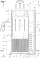
- the heatsink 4 is attached to the housing 2 through a bracket 25 and a support frame 26 (refer to FIG. 7 ).
- the intake unit 5 introduces air from outside the housing 2 into the housing 2.
- the intake unit 5 introduces the air into a buffer space BF to be described later inside the housing 2.
- the intake unit 5 is provided on a portion toward an upper side of the center of a wall portion 2c on the front side of the housing 2.
- the intake unit 5 includes an intake filter (filter unit) 51, a filter holding portion 52, and intake ports 53.
- the intake filter 51 captures foreign matter (dust and the like) contained in the air introduced into the housing 2.
- the intake filter 51 is made of, for example, urethane or the like.
- the intake filter 51 has a rectangular plate-shaped outer shape.
- the intake filter 51 extends over the portion toward the upper side of the center of the wall portion 2c when viewed from the front.
- the filter holding portion 52 houses and holds the intake filter 51.
- the filter holding portion 52 includes an outer plate 52x having a rectangular plate shape with the Y direction as a thickness direction.
- a front surface of the outer plate 52x is located on the same plane as a front surface of the wall portion 2c of the housing 2.
- the filter holding portion 52 is detachably attached to the duct 7 and the support frame 27 provided on the duct 7.
- the intake ports 53 are through-holes that are open along the Y direction (direction intersecting a direction from the heatsink 4 toward the exhaust unit 6), and that communicate with the inside of the housing 2.
- the intake ports 53 are arranged in proximity to each other in regions at both end portions in the X direction of the outer plate 52x.
- the intake ports 53 are through-holes having an elongated hole shape with the Z direction as a longitudinal direction. Air suctioned from the intake ports 53 is introduced into the buffer space BF inside the housing 2 through the intake filter 51 (refer to FIG. 8 ).
- the exhaust unit 6 discharges the air from inside the housing 2 to the outside of the housing 2.
- the exhaust unit 6 is provided on an upper end portion of the housing 2.
- the exhaust unit 6 includes a fan 61.
- an axial fan is used as the fan 61.
- the fan 61 delivers the air, which is suctioned from the lower side along the Z direction, to the upper side under pressure along the Z direction.
- the fan 61 is fixed to an upper end portion inside the housing 2.
- An exhaust filter 62 made of, for example, urethane or the like is attached to the upper wall 2a of the housing 2 located on a discharge side of the fan 61.
- the exhaust filter 62 is illustrated only in the FIG. 2 for the sake of convenience, and the illustration in the other drawings is omitted.
- an external pipe for outdoor exhaust (not illustrated) is connected to the discharge side of the fan 61 of the exhaust unit 6.
- the duct 7 is provided between the heatsink 4 and the exhaust unit 6 inside the housing 2.
- the duct 7 allows the air, which has passed through the heatsink 4, to flow through to the exhaust unit 6.
- the duct 7 allows an inert gas, which has passed through the heatsink 4, to flow through to the exhaust unit 6.
- the duct 7 has a rectangular pipe shape.
- the duct 7 includes a linear portion 71 extending in the Z direction with a constant cross-sectional area, and an enlarged portion 72 provided on a downstream side of the linear portion 71 and extending in the Z direction such that the cross-sectional area increases as the enlarged portion 72 extends downstream.
- the buffer space BF (refer to FIG. 8 ) that is a space into which air is introduced from outside by the intake unit 5 is provided on one side and the other side in the X direction of the duct 7 inside the housing 2.
- the buffer space BF is a space defined by inner surfaces of the housing 2 and outer surfaces of the linear portion 71 and the enlarged portion 72 of the duct 7.
- Lower end portions of the duct 7 are inserted and fixed to grooves 47 formed in the heat radiation fins 42 of the heatsink 4.
- An upper end portion of the duct 7 is fixed to a suction side of the fan 61.
- the duct 7 is attached to the housing 2 through the support frame 27.
- the inert gas supply unit 8 supplies inert gas to the outside of the housing 2.
- the inert gas include nitrogen.
- the inert gas supply unit 8 forms a region, which is dominated by the inert gas (region with low oxygen concentration), in a region including an irradiation region of light from the plurality of LED elements 32, by supplying the inert gas.
- the inert gas supply unit 8 is attached to a lower end portion of the wall portion 2c on the front side of the housing 2.
- the inert gas supply unit 8 includes a purge housing 81 having a rectangular box shape; a socket 82 provided on an upper end surface of the purge housing 81; and a spray port 83 provided at a lower end portion of the purge housing 81.
- the inert gas is introduced from the socket 82 into the purge housing 81, and the inert gas is sprayed from the spray port 83.
- the inert gas suction unit 9 suctions the inert gas outside the housing 2, and causes the inert gas to flow into the housing 2.
- the inert gas suction unit 9 is a structure attached to the housing 2.
- the inert gas suction unit 9 is detachably attached to a rear side of the lower wall 2b of the housing 2 by fasteners such as screws.
- the inert gas suction unit 9 includes a suction unit housing 91 having a rectangular box shape; a suction port 92 provided in a lower surface of the suction unit housing 91; and a recovery flow path 93 provided inside the suction unit housing 91 (refer to FIG. 7 ).
- the inert gas is suctioned into the suction unit housing 91 through the suction port 92, and the inert gas is allowed to flow through into the housing 2 by the recovery flow path 93.
- outside air is introduced into the buffer space BF inside the housing 2 by the intake unit 5.
- the air introduced into the buffer space BF flows downward along the Z direction, and then passes through the heatsink 4 and flows into the duct 7.
- the heatsink 4 the air flows downward along the Z direction between the plurality of heat radiation fins 42 of each of the pair of outer portions 42x, and then flows to pass through between the partition plates 44 and the base plate 41 and to turn upward, and merges at the inner portion 42y. Then, the air flows upward along the Z direction between the plurality of heat radiation fins 42 of the inner portion 42y, and flows into the duct 7.
- the air introduced into the buffer space BF flows downward along the Z direction, and then passes through the driver substrate heatsink 13.
- the air that has passed through the driver substrate heatsink 13 merges with the flow in the inner portion 42y of the heatsink 4 through a lower rear space inside the housing 2, flows upward along the Z direction between the plurality of heat radiation fins 42 of the inner portion 42y, and flows into the duct 7.
- the air that has flowed into the duct 7 flows upward along the Z direction, and is discharged to the outside of the housing 2 through the fan 61.
- the inert gas sprayed from the inert gas supply unit 8 is suctioned by the inert gas suction unit 9, and flows into the housing 2.
- the inert gas that has flowed into the housing 2 merges with the flow in the inner portion 42y of the heatsink 4 through the lower rear space inside the housing 2, flows upward along the Z direction between the plurality of heat radiation fins 42 of the inner portion 42y, together with the air, and flows into the duct 7.
- the inert gas that has flowed into the duct 7 flows upward along the Z direction, together with the air, and is discharged to the outside of the housing 2 through the fan 61, together with the air.
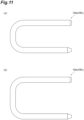
- the heat pipe 43 of the heatsink 4 is bent in a U shape and extends when viewed in the X direction.
- the heat pipe 43 linearly extends in the Z direction when viewed in the Y direction.
- the heat pipe 43 includes a pair of first heat pipes 48a and 48b provided spaced apart from each other in the X direction, and a pair of second heat pipes 49a and 49b provided spaced apart from each other in the X direction between the pair of first heat pipes 48a and 48b.
- the second heat pipes 49a and 49b are longer than the first heat pipes 48a and 48b.
- the heat pipes 43 adjacent to each other differ by 180° in the direction of the U shape (direction of an opening side of the U shape).
- the first heat pipe 48a and the second heat pipe 49b that are not adjacent to each other linearly extend rearward along the Y direction so as to be in contact with the base plate 41, and then extend to be bent upward and forward, and linearly extend forward along the Y direction.
- the first heat pipe 48b and the second heat pipe 49a that are not adjacent to each other linearly extend forward along the Y direction so as to be in contact with the base plate 41, and then extend to be bent upward and rearward, and linearly extend rearward along the Y direction.
- a linearly extending portion of the heat pipe 43 is brazed and fixed to the plurality of heat radiation fins 42.
- the partition plates 44 are provided such that upper end surfaces of the partition plates 44 are located on the same plane as upper end surfaces of the heat radiation fins 42.
- the partition plates 44 extend such that lower ends of the partition plates 44 are located between the center of the heat radiation fins 42 and the base plate 41 in the Z direction. Namely, as described above, the lower ends of the partition plates 44 are spaced apart from the base plate 41.
- the partition plates 44 extend to intersect all the heat radiation fins 42 in the Y direction.
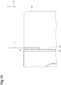
- the partition plates 44 are interposed in slits 46 formed in the plurality of heat radiation fins 42.
- the slits 46 are open on the side opposite to the base plate 41 side, and are open in the Y direction.
- a thickness of the partition plates 44 is less than or equal to a width in the X direction of the slits 46.
- the slits 46 are each provided between the first heat pipe 48a and the second heat pipe 49a adjacent to each other and between the first heat pipe 48b and the second heat pipe 49b adjacent to each other in the X direction.
- the partition plates 44 are each provided between the first heat pipe 48a and the second heat pipe 49a adjacent to each other and between the first heat pipe 48b and the second heat pipe 49b adjacent to each other.
- the lower end portions of the duct 7 are inserted into the grooves 47 formed in the heat radiation fins 42 of the heatsink 4.
- a pair of side walls facing each other in the X direction protrude downward.
- the grooves 47 are open upward and are open in the Y direction.
- the grooves 47 are provided to continue with the slits 46 at upper end portions of the plurality of heat radiation fins 42.
- a thickness of the lower end portion of the duct 7 is less than or equal to a width in the X direction of the groove 47.
- the lower end portions of the duct 7 are press-fitted into the grooves 47 through a heat conductive grease (heat conductive material). Accordingly, the lower end portions of the duct 7 are fixed to the plurality of heat radiation fins 42 while being thermally connected thereto, and are in overlapping contact with outer sides in the X direction of the partition plates 44. As a result, the inner portion 42y of the plurality of heat radiation fins 42 partitioned off by the partition plates 44 communicates with the inside of the duct 7 in an airtight manner.
- the heat conductive grease is not particularly limited, and various greases can be used.
- the buffer space BF illustrated in FIG. 8 is formed inside the housing 2.
- the buffer space BF forms a flow path allowing the air to flow from the upper side into the gaps between the plurality of heat radiation fins 42 in the pair of outer portions 42x of the heatsink 4.
- the heatsink 4 when the air flows into the plurality of heat radiation fins 42 from the side opposite to the base plate 41 side, due to the presence of the partition plates 44, the air flows to the base plate 41 side between the plurality of heat radiation fins 42, and then flows in the X direction, turns, and flows to a side away from the base plate 41. Therefore, the air can effectively flow between the plurality of heat radiation fins 42, and the cooling efficiency (heat radiation efficiency) can be enhanced.
- the cooling efficiency heat radiation efficiency
- the flows of air between the plurality of heat radiation fins 42 can be rectified, the air can effectively flow, and the cooling efficiency can be enhanced. As a result, the downsizing and weight reduction of the heatsink 4 and the active energy irradiation device 1 including the heatsink 4 can be achieved.
- the lower ends of the partition plates 44 are spaced apart from the base plate 41. In this case, a space allowing the air to flow through can be created between the lower end of the partition plates 44 and the base plate 41.
- a configuration can be specifically realized in which more air can pass through in the X direction between the plurality of heat radiation fins 42 on the base plate 41 side than on the side opposite to the base plate 41 side.
- the partition plates 44 are brazed to the plurality of heat radiation fins 42. Accordingly, the plurality of heat radiation fins 42 and the partition plates 44 are thermally connected, so that heat of the plurality of heat radiation fins 42 can be effectively diffused by the partition plates 44.
- the slits 46 that are open on the side opposite to the base plate 41 side are formed in the plurality of heat radiation fins 42.
- the partition plates 44 are interposed in the slits 46 of the plurality of heat radiation fins 42. In this case, the partition plates 44 can be easily provided. The partition plates 44 can be reliably fixed to the plurality of heat radiation fins 42.
- the pair of partition plates 44 are provided spaced apart from each other.
- the pair of partition plates 44 can partition the plurality of heat radiation fins 42.
- the heatsink 4 includes the heat pipe 43 provided to be embedded in the plurality of heat radiation fins. In this case, heat can be effectively radiated using the heat pipe 43.
- the heat pipe 43 includes the first heat pipes 48a and 48b provided in pair, and the pair of second heat pipes 49a and 49b provided between the pair of first heat pipes 48a and 48b and longer than the first heat pipes 48a and 48b.
- the partition plates 44 are each provided between the first heat pipe 48a and the second heat pipe 49a adjacent to each other and between the first heat pipe 48b and the second heat pipe 49b adjacent to each other.
- the air flowing downward can come into contact with the first heat pipes 48a and 48b, and then the air that turns and flows upward can come into contact with the second heat pipes 49a and 49b.
- the air flowing between the plurality of heat radiation fins 42 can come into contact with the first heat pipes 48a and 48b in a state where the temperature is still relatively low, and thereafter, in a state where the temperature has risen, the air can come into contact with the second heat pipes 49a and 49b having a higher heat radiation capacity than that of the first heat pipes 48a and 48b. Accordingly, heat can be uniformly radiated using the heat pipe 43.
- the grooves 47 that are open upward are each formed in the plurality of heat radiation fins 42.
- the duct 7 can be engaged with the heat radiation fins 42 using the grooves 47.
- the active energy irradiation device 1 includes the heatsink 4, the LED elements 32, and the housing 2. Inside the housing 2, the buffer space BF is provided as a flow path allowing the air to flow from the upper side into the gaps between the plurality of heat radiation fins 42. Accordingly, the air that has flowed into the heatsink 4 flows to the base plate 41 side between the plurality of heat radiation fins 42, and then turns in the X direction, and flows to the side away from the base plate 41 between the plurality of heat radiation fins 42. Therefore, the air can effectively flow between the plurality of heat radiation fins 42, and the cooling efficiency can be enhanced.
- the pair of partition plates 44 partition the plurality of heat radiation fins 42 of the heatsink 4 into the pair of outer portions 42x and the inner portion 42y therebetween.
- the buffer space BF is provided as a flow path allowing the air to flow from the upper side into the gaps between the plurality of heat radiation fins 42 in each of the pair of outer portions 42x. Accordingly, the air that has flowed into the heatsink 4 flows to the base plate 41 side between the plurality of heat radiation fins 42 in each of the pair of outer portions 42x, and then turns in the X direction, merges, and flows to the side away from the base plate 41 between the plurality of heat radiation fins 42 in the inner portion 42y.
- the LED elements 32 on both end sides in the X direction which are likely to become overheated, are preferentially cooled, so that the temperature of the plurality of LED elements 32 can be made uniform, and the occurrence of irradiation unevenness in the plurality of LED elements 32 can be suppressed.
- one end portions on the base plate 41 side of the duct 7 are inserted into the grooves 47 of the heat radiation fins 42. Accordingly, the duct 7 can be engaged with the heat radiation fins 42 using the grooves 47, and the need for a seal member such as a packing at a connection between the duct 7 and the heat radiation fins 42 can be eliminated.
- the one end portions on the base plate 41 side of the duct 7 are inserted into the grooves 47 of the heat radiation fins 42 through a heat conductive grease.
- Heat can be effectively transferred from the plurality of heat radiation fins 42 to the duct 7 by the heat conductive grease.
- the heat conductive grease instead of the heat conductive grease, other heat conductive materials may be used. Examples of the other heat conductive materials include a heat conductive sheet, a heat conductive tape, a heat conductive gel, and a heat conductive pad.
- the LED elements 32 perform irradiation with ultraviolet rays. Accordingly, the active energy irradiation device 1 can be used as a device that performs irradiation with ultraviolet rays.
- the active energy irradiation system 100 includes the plurality of active energy irradiation devices 1, and the plurality of active energy irradiation devices 1 are arranged to be in contact with each other in the X direction.
- the plurality of active energy irradiation devices 1 are arranged to be in contact with each other in the X direction, in each of the active energy irradiation devices 1, due to the influence of other adjacent active energy irradiation devices 1, the plurality of LED elements 32 are likely to become overheated (particularly, the LED elements 32 on both the end sides in the X direction are likely to become overheated).
- the active energy irradiation system 100 includes the active energy irradiation devices 1, the cooling efficiency can be enhanced, so that the overheating of the plurality of LED elements 32 can be suppressed.
- FIG. 13 is a view illustrating a thermal camera image of a periphery of the LED substrates 3 in the active energy irradiation device 1.
- FIG. 13 is an image of the lower wall 2b of the housing 2 when viewed from below.
- the temperature profile of the plurality of LED substrates 3 (plurality of LED elements 32 (refer to FIG. 3 )) can be made uniform through cooling.
- the temperature distribution of the plurality of LED substrates 3 can be made uniform with a temperature gradient within 2°C.
- One mode of the present disclosure is not limited to the embodiment.
- the lower ends of the partition plates 44 of the heatsink 4 are spaced apart from the base plate 41; however, the configuration is not limited as long as the configuration allows more air to pass through in the X direction between the plurality of heat radiation fins 42 on the base plate 41 side than on the side opposite to the base plate 41 side, and the configuration may be as follows.
- a ventilation portion for example, a hole, a mesh portion, or the like
- the ventilation portion can be used as a space through which the air passes.
- the configuration can be specifically realized in which more air passes through in the X direction between the plurality of heat radiation fins 42 on the base plate 41 side than on the side opposite to the base plate 41 side.
- the partition plate 44 may include a mesh portion, and the base plate 41 side of the mesh portion may have a larger opening ratio than that of the side opposite to the base plate 41 in the mesh portion.
- the mesh portion can be used as a space through which the air passes
- the base plate 41 side of the mesh portion can be used as a space through which more air passes.
- the configuration can be specifically realized in which more air passes through in the X direction between the plurality of heat radiation fins 42 on the base plate 41 side than on the side opposite to the base plate 41 side.
- the heatsink 4 includes the partition plates 44, but is not limited to including the partition plates 44, and may include other various partition members as long as the partition members can partition the heatsink 4.
- the LED elements 32 as active energy irradiation units perform irradiation with ultraviolet rays; however, the active energy irradiation units may perform irradiation with electron beams.
- the active energy irradiation device can be used as a device that performs irradiation with electron beams.
- the heatsink 4 is used to radiate heat from the LED elements 32, and the LED element 32 is a heat-generating unit; however, the heat-generating unit from which the heatsink 4 has to radiate heat is not limited to the LED element 32, and may be other heat-generating units.
- the lower end portions of the duct 7 are inserted into the grooves 47 of the heat radiation fins 42 of the heatsink 4; however, the object to be inserted into the grooves 47 is not limited to the duct 7, and may be other members. In this case, the other members can be engaged with the heat radiation fins 42 using the grooves 47.
- the duct 7 has a rectangular pipe shape; however, the shape of the duct 7 is not particularly limited, and may have, for example, other polygonal pipe shapes.
- the exhaust unit 6 includes the fan 61; however, the configuration of the exhaust unit 6 is not particularly limited.
- the exhaust unit 6 may include a pipe for discharging the air and the inert gas to the outdoors, without including the fan 61.
- the air and the inert gas may be delivered under pressure by a blower or the like at a connection destination on a downstream side of the pipe.
- an air presence region exists around the linear portion 71 and the enlarged portion 72 of the duct 7; however, the air presence region may exist around only one of the linear portion 71 and the enlarged portion 72, or the air presence region may exist around only a part of the linear portion 71 or a part of the enlarged portion 72.
- the inert gas suction unit 9 is detachably attached to the housing 2 by fasteners such as screws; however, the configuration for detachable attachment is not particularly limited, and a known configuration can be used.
- the inert gas suction unit 9 may be detachably attached to the housing 2 by sliding the inert gas suction unit 9 with respect to the housing 2.
- the heatsink 4 provided with the pair of partition plates 44 is used; however, the number of the partition plates 44 in the heatsink 4 is not limited, and may be one or plural.
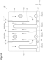
- a heatsink 4Z may be used in which the partition plate 44 is further provided to partition the inner portion 42y of the heatsink 4 described above (refer to FIG. 10 ) in the X direction.
- the partition plate 44 that is further provided is disposed between the second heat pipes 49a and 49b in the X direction.
- the plurality of heat radiation fins 42 are partitioned into the pair of outer portions 42x and the inner portion 42y by the pair of partition plates 44, and the inner portion 42y is partitioned into a first inner portion 42y1 and a second inner portion 42y2 by the partition plate 44 that is further provided between the pair of partition plates 44.
- the air flows to the base plate 41 side along the Z direction between the plurality of heat radiation fins 42 of each of the pair of outer portions 42x, and then flows to pass through between the partition plate 44 and the base plate 41 and to turn upward.
- the air flows away from the base plate 41 along the Z direction between the plurality of heat radiation fins 42 of each of the first inner portion 42y1 and the second inner portion 42y2, and flows into the duct 7.
- the partition plate 44 may be further provided at the location.
- the active energy irradiation system 100 includes the plurality of active energy irradiation devices 1 arranged in one row in the X direction, but is not limited thereto.
- the number and disposition of the active energy irradiation devices according to one mode of the present disclosure is not particularly limited, may be changed as appropriate depending on the system specifications or the like, and, for example, may be configured as in an active energy irradiation system 100Z illustrated in FIG. 15 .
- the active energy irradiation system 100Z includes a pair of units each including a plurality of active energy irradiation devices 1Z fixed to the fixing plate 11 and arranged to be in contact with each other in the X direction. In the example illustrated in FIG.
- the active energy irradiation devices 1Z are arranged in the Y direction such that back surfaces (rear surfaces) of the active energy irradiation devices 1Z are in contact with each other.
- the active energy irradiation device 1Z has the same configuration as the active energy irradiation device 1 (refer to FIG. 2 ) except that the inert gas supply unit 8 is not provided.
- the plurality of active energy irradiation devices 1 and 1Z can be in contact (connection) with a cooling surface of the housing 2 (wall surface of the housing 2 which is adjacent to a region where air exists before passing through the heatsink 4 inside the housing 2).
- the heatsinks 4 and 4Z when viewed in the Y direction, at least one of a pair of facing sides among sides forming the slit 46 may be bent to enter the inside of the slit 46.
- inner surfaces of the slit 46 act as a spring (caulking) due to the fact that the side is bent, and reliable contact between the partition plate 44 and the heat radiation fins 42 is obtained, so that heat can be effectively transferred therebetween.
Landscapes
- Engineering & Computer Science (AREA)
- General Engineering & Computer Science (AREA)
- Physics & Mathematics (AREA)
- Thermal Sciences (AREA)
- Mechanical Engineering (AREA)
- Microelectronics & Electronic Packaging (AREA)
- Life Sciences & Earth Sciences (AREA)
- Sustainable Development (AREA)
- Geometry (AREA)
- Cooling Or The Like Of Electrical Apparatus (AREA)
- Cooling Or The Like Of Semiconductors Or Solid State Devices (AREA)
- Physical Or Chemical Processes And Apparatus (AREA)
Abstract
Description
- The present disclosure relates to a heatsink, an active energy irradiation device, and an active energy irradiation system.
- In the related art, a heatsink has been known that includes a base plate thermally connected to a heat-generating unit, and a plurality of heat radiation fins erected on a surface of the base plate, and arranged with gaps in a first direction along the surface (for example, refer to Patent Literature 1).
- Patent Literature 1:
Japanese Unexamined Patent Publication No. 2001-118972 - In the heatsink as described above, for example, even when the amount of heat generated by the heat-generating unit increases, it is desirable to enhance cooling efficiency in order to realize downsizing and weight reduction.
- An object of the present disclosure is to provide a heatsink, an active energy irradiation device, and an active energy irradiation system capable of enhancing cooling efficiency.
- According to one aspect of the present disclosure, there is provided a heatsink including: a base plate thermally connected to a heat-generating unit; a plurality of heat radiation fins erected on a surface of the base plate, and arranged with gaps in a first direction along the surface; and a partition member provided to intersect the plurality of heat radiation fins, and partitioning the plurality of heat radiation fins in a second direction along the surface and intersecting the first direction. The partition member partitions the plurality of heat radiation fins such that more air passes through in the second direction between the plurality of heat radiation fins on a base plate side than on a side opposite to the base plate side.
- In this heatsink, for example, when the air flows into the plurality of heat radiation fins from the side opposite to the base plate side, due to the presence of the partition member, the air flows to the base plate side between the plurality of heat radiation fins, and then flows in the second direction, turns, and flows to a side away from the base plate. Therefore, the air can effectively flow between the plurality of heat radiation fins, and the cooling efficiency can be enhanced.
- In the heatsink according to one aspect of the present disclosure, an end on the base plate side of the partition member may be spaced apart from the base plate. In this case, a space allowing the air to pass through can be created between the end on the base plate side of the partition member and the base plate. A configuration can be specifically realized in which more air passes through in the second direction between the plurality of heat radiation fins on the base plate side than on the side opposite to the base plate side.
- In the heatsink according to one aspect of the present disclosure, a ventilation portion allowing the air to pass through may be provided on the base plate side of the partition member. In this case, the ventilation portion can be used as a space through which the air passes. The configuration can be specifically realized in which more air passes through in the second direction between the plurality of heat radiation fins on the base plate side than on the side opposite to the base plate side.
- In the heatsink according to one aspect of the present disclosure, the partition member may include a mesh portion, and the base plate side of the mesh portion may have a larger opening ratio than an opening ratio of the side opposite to the base plate side in the mesh portion. In this case, the mesh portion can be used as a space through which the air passes, and the base plate side of the mesh portion can be used as a space through which more air passes. The configuration can be specifically realized in which more air passes through in the second direction between the plurality of heat radiation fins on the base plate side than on the side opposite to the base plate side.
- In the heatsink according to one aspect of the present disclosure, the partition member may be brazed to the plurality of heat radiation fins. Accordingly, the plurality of heat radiation fins and the partition member are thermally connected, so that heat of the plurality of heat radiation fins can be effectively diffused by the partition member.
- In the heatsink according to one aspect of the present disclosure, a slit that is open on the side opposite to the base plate side may be formed in the plurality of heat radiation fins, and the partition member may be interposed in the slit of the plurality of heat radiation fins. In this case, the partition member can be easily provided.
- In the heatsink according to one aspect of the present disclosure, when viewed in the first direction, at least one of a pair of facing sides among sides forming the slit may be bent to enter an inside of the slit. In this case, when the partition member is inserted to be interposed in the slit, inner surfaces of the slit act as a spring (caulking) due to the fact that the side is bent, and reliable contact between the partition member and the heat radiation fins is obtained, so that heat can be effectively transferred therebetween.
- In the heatsink according to one aspect of the present disclosure, a pair of the partition members may be provided spaced apart from each other. In this case, the pair of partition members can partition the plurality of heat radiation fins.
- The heatsink according to one aspect of the present disclosure may further include a heat pipe provided to be embedded in the plurality of heat radiation fins and thermally connected to the plurality of heat radiation fins. In this case, heat can be effectively radiated using the heat pipe.
- In the heatsink according to one aspect of the present disclosure, the heat pipe may include a pair of first heat pipes provided spaced apart from each other so as to be embedded in the plurality of heat radiation fins, and a pair of second heat pipes provided spaced apart from each other so as to be embedded between the pair of first heat pipes in the plurality of heat radiation fins, and longer than the first heat pipes. The partition members may be each provided between one first heat pipe and one second heat pipe adjacent to each other and between the other first heat pipe and the other second heat pipe adjacent to each other. In this case, for example, between the plurality of heat radiation fins, the air flowing to the base plate side can come into contact with the first heat pipes, and then the air that turns and flows to a side away from the base plate can come into contact with the second heat pipes. Namely, the air flowing between the plurality of heat radiation fins can come into contact with the first heat pipes in a state where the temperature is still relatively low, and thereafter, in a state where the temperature has risen, the air can come into contact with the second heat pipes having a higher heat radiation capacity than that of the first heat pipes. Accordingly, heat can be uniformly radiated using the heat pipe.
- In the heatsink according to one aspect of the present disclosure, grooves that are open on the side opposite to the base plate side may be each formed in the plurality of heat radiation fins. In this case, other members can be engaged with the heat radiation fins using the groove.
- According to one aspect of the present disclosure, there is provided an active energy irradiation device including: the heatsink; a plurality of active energy irradiation units thermally connected to the base plate of the heatsink, and arranged at least along a predetermined direction; and a housing that houses the heatsink and the active energy irradiation units. A flow path allowing the air to flow into the gaps between the plurality of heat radiation fins from the side opposite to the base plate side may be provided inside the housing.
- In this active energy irradiation device, the air that has flowed to the heatsink flows to the base plate side between the plurality of heat radiation fins, and then turns in the second direction, and flows to a side away from the base plate between the plurality of heat radiation fins. Therefore, the air can effectively flow between the plurality of heat radiation fins, and the cooling efficiency can be enhanced.
- According to one aspect of the present disclosure, there is provided an active energy irradiation device including: the heatsink; a plurality of active energy irradiation units thermally connected to the base plate of the heatsink, and arranged at least along a predetermined direction; and a housing that houses the heatsink and the active energy irradiation units. The pair of partition members of the heatsink partition the plurality of heat radiation fins of the heatsink into a pair of outer portions located outside in the predetermined direction and an inner portion located between the pair of outer portions. A flow path allowing the air to flow into the gaps between the plurality of heat radiation fins in the pair of outer portions from the side opposite to the base plate side is provided inside the housing.
- In this active energy irradiation device, the air that has flowed into the plurality of heat radiation fins of the heatsink flows to the base plate side between the plurality of heat radiation fins in each of the pair of outer portions, and then turns in the second direction, merges, and flows to a side away from the base plate between the plurality of heat radiation fins in the inner portion. Therefore, the air can effectively flow between the plurality of heat radiation fins, and the cooling efficiency can be enhanced.
- According to one aspect of the present disclosure, there is provided an active energy irradiation device including: the heatsink; a plurality of active energy irradiation units thermally connected to the base plate of the heatsink, and arranged at least along a predetermined direction; a housing that houses the heatsink and the active energy irradiation units; an exhaust unit that is provided in the housing, and that discharges the air, which has passed through the heatsink, to an outside of the housing; and a duct provided between the heatsink and the exhaust unit inside the housing, and allowing the air, which has passed through the heatsink, to flow through to the exhaust unit. One end portion on the base plate side of the duct is inserted into the grooves.
- In this active energy irradiation device, the air that has flowed into the plurality of heat radiation fins of the heatsink flows to the base plate side between the plurality of heat radiation fins in one of a first portion and a second portion, and then turns in the second direction, and flows to a side away from the base plate between the plurality of heat radiation fins in the other of the first portion and the second portion. Therefore, the air can effectively flow between the plurality of heat radiation fins, and the cooling efficiency can be enhanced. In addition, the duct can be engaged with the heat radiation fins using the groove, and the need for a seal member such as a packing at a connection between the duct and the heat radiation fins can be eliminated.
- In the active energy irradiation device according to one aspect of the present disclosure, the one end portion on the base plate side of the duct may be inserted into the grooves through a heat conductive material. In this case, heat can be effectively transferred from the plurality of heat radiation fins to the duct.
- In the active energy irradiation device according to one aspect of the present disclosure, the active energy irradiation units may perform irradiation with an ultraviolet ray or an electron beam. Accordingly, the active energy irradiation device can be used as a device that performs irradiation with an ultraviolet ray or an electron beam.
- According to one aspect of the present disclosure, there is provided an active energy irradiation system including: a plurality of the active energy irradiation devices. The plurality of active energy irradiation devices are arranged to be in contact with each other in the predetermined direction.
- When the plurality of active energy irradiation devices are arranged to be in contact with each other in the predetermined direction, in each of the active energy irradiation devices, due to the influence of other adjacent active energy irradiation devices, the plurality of active energy irradiation units are likely to become overheated (particularly, the plurality of active energy irradiation units are likely to become overheated that are located at both end portions in the predetermined direction among the plurality of active energy irradiation units). In this respect, since the active energy irradiation system according to one aspect of the present disclosure includes the active energy irradiation system, the cooling efficiency can be enhanced, so that the overheating of the plurality of active energy irradiation units can be suppressed.
- According to the present disclosure, it is possible to provide the heatsink, the active energy irradiation device, and the active energy irradiation system capable of enhancing cooling efficiency.
-
-
FIG. 1 is a perspective view of an active energy irradiation system according to one embodiment. -
FIG. 2 is a perspective view of an active energy irradiation device illustrated inFIG. 1 . -
FIG. 3 is a perspective view of the active energy irradiation device illustrated inFIG. 2 when viewed from below. -
FIG. 4 is an exploded perspective view of the active energy irradiation device illustrated inFIG. 2 . -
FIG. 5 is a perspective view illustrating an internal configuration of a housing in the active energy irradiation device illustrated inFIG. 2 . -
FIG. 6 is a front view illustrating the flows of air in the active energy irradiation device illustrated inFIG. 2 . -
FIG. 7 is a cross-sectional view of the active energy irradiation device taken along line A-A illustrated inFIG. 6 . -
FIG. 8 is an end view of the active energy irradiation device taken along line B-B illustrated inFIG. 7 . -
FIG. 9 is a perspective view of a heatsink illustrated inFIG. 4 . -
FIG. 10 is a front view of the heatsink illustrated inFIG. 4 . -
FIG. 11(a) is a front view of a first heat pipe of the heatsink illustrated inFIG. 4 .FIG. 11(b) is a front view of a second heat pipe of the heatsink illustrated inFIG. 4 . -
FIG. 12 is a partial enlarged front view of the heatsink illustrated inFIG. 4 . -
FIG. 13 is a view illustrating a thermal camera image of a periphery of LED substrates in the active energy irradiation device illustrated inFIG. 1 . -
FIG. 14 is a front view of a heatsink according to a modification example. -
FIG. 15 is a perspective view of an active energy irradiation system according to a modification example. - Hereinafter, an embodiment of the present disclosure will be described in detail with reference to the drawings. It should be noted that in the drawings, the same or equivalent portions are denoted by the same reference signs, and duplicate descriptions will be omitted.
- As illustrated in
FIG. 1 , an activeenergy irradiation system 100 is, for example, a system that is installed in an ultraviolet (UV) printer, and includes a plurality of activeenergy irradiation devices 1. The activeenergy irradiation devices 1 are, for example, high-output air-cooled LED light sources for printing applications. The activeenergy irradiation devices 1 irradiate an irradiation target with light (ultraviolet rays, active energy rays) to dry ink on the irradiation target. Examples of the irradiation target include a printed matter to which a photocurable ink is adhered. - The active
energy irradiation devices 1 have a rectangular parallelepiped outer shape. The activeenergy irradiation devices 1 are arranged to be in contact with each other in a predetermined direction. The plurality of activeenergy irradiation devices 1 arranged in the predetermined direction are fixed and held by a fixingplate 11. As illustrated inFIGS. 2 ,3 ,4 , and5 , the activeenergy irradiation device 1 includes ahousing 2, a plurality ofLED substrates 3, aheatsink 4, anintake unit 5, anexhaust unit 6, aduct 7, an inertgas supply unit 8, and an inertgas suction unit 9. - Incidentally, for convenience of description, the predetermined direction in which the plurality of active
energy irradiation devices 1 are arranged is defined as an "X direction", a direction perpendicular to the X direction, which is a light emission direction of the activeenergy irradiation devices 1, is defined as a "Z direction", and a direction orthogonal to the X direction and the Z direction is defined as a "Y direction". A side of the activeenergy irradiation device 1 from which light is emitted is defined as a "lower side", and the opposite side is defined as an "upper side". One side in the Y direction is defined as a "front side", and the other side in the Y direction is defined as a "rear side". - The
housing 2 has a rectangular shape that is elongated in the Z direction. Thehousing 2 is made of metal. Thehousing 2 houses theLED substrates 3, theheatsink 4, and theduct 7. Thehousing 2 is configured by assembling afront casing 21 and arear casing 22 to each other. Agrip portion 23 for grasping thehousing 2 is provided on anupper wall 2a of thehousing 2. Adriver substrate 12 with the Y direction as a thickness direction is disposed on the rear side inside thehousing 2. Thedriver substrate 12 is an electrical driving circuit substrate for driving the activeenergy irradiation device 1. Adriver substrate heatsink 13 that cools transistors and the like of thedriver substrate 12 is disposed on thedriver substrate 12. Thedriver substrate heatsink 13 is thermally connected to the transistors and the like of thedriver substrate 12. - The
LED substrate 3 includes asubstrate 31 having a rectangular plate shape and constituting a predetermined circuit (refer toFIG. 8 ), and LED elements (active energy irradiation units) 32 that are light-emitting elements arranged at predetermined pitches in the X direction and the Y direction on thesubstrate 31. TheLED elements 32 emit light (ultraviolet rays) downward. TheLED substrates 3 are disposed at a lower end portion inside thehousing 2 with the Z direction as a thickness direction of thesubstrates 31. TheLED substrates 3 are arranged along the X direction. Accordingly, several to several hundredLED elements 32 are arranged at least in the X direction inside thehousing 2. The irradiation target moving in the Y direction is irradiated with light emitted from each of theLED elements 32 on theLED substrates 3 through alight irradiation window 24 made of a glass plate and provided on alower wall 2b of thehousing 2. - The
heatsink 4 is a heat radiation member thermally connected to theLED elements 32 on theLED substrates 3. Theheatsink 4 is an air-cooled heatsink that radiates heat through heat exchange with air. Air constitutes a heat transfer medium (coolant) for cooling theLED elements 32. Theheatsink 4 includes abase plate 41,heat radiation fins 42, aheat pipe 43, and a partition plate (partition member) 44. - The
base plate 41 has a rectangular plate shape. The plurality ofLED substrates 3 are provided on a lower surface of thebase plate 41. The lower surface of thebase plate 41 is in contact with thesubstrates 31 of theLED substrates 3. Theheat radiation fins 42 have a flat plate shape with the Y direction as a thickness direction. Theheat radiation fins 42 are erected on an upper surface (surface) of thebase plate 41. Theheat radiation fins 42 are arranged to be stacked with gaps therebetween in the Y direction (first direction). - The
heat pipe 43 is provided to be embedded in a plurality of theheat radiation fins 42. Theheat pipe 43 is thermally connected to the plurality ofheat radiation fins 42. Thepartition plate 44 is provided to intersect the plurality ofheat radiation fins 42. Thepartition plate 44 has a flat plate shape with the X direction as a thickness direction. Thepartition plate 44 partitions the plurality ofheat radiation fins 42 in the X direction (second direction). A pair of thepartition plates 44 are provided spaced from each other in the X direction on the plurality ofheat radiation fins 42. The pair ofpartition plates 44 partition the plurality ofheat radiation fins 42 into a pair ofouter portions 42x located outside in the X direction and aninner portion 42y located between the pair of outer portions. - Ends on a
base plate 41 side of thepartition plates 44 are spaced apart from thebase plate 41. Namely, thepartition plates 44 partition the plurality ofheat radiation fins 42 such that more air passes through in the X direction between the plurality ofheat radiation fins 42 on the lower side (base plate 41 side) than on the upper side (side opposite to thebase plate 41 side). Thepartition plates 44 are brazed and fixed to the plurality ofheat radiation fins 42. Theheatsink 4 is attached to thehousing 2 through abracket 25 and a support frame 26 (refer toFIG. 7 ). - The
intake unit 5 introduces air from outside thehousing 2 into thehousing 2. Theintake unit 5 introduces the air into a buffer space BF to be described later inside thehousing 2. Theintake unit 5 is provided on a portion toward an upper side of the center of awall portion 2c on the front side of thehousing 2. Theintake unit 5 includes an intake filter (filter unit) 51, afilter holding portion 52, andintake ports 53. - As illustrated in
FIGS. 4 ,5 ,6 , and7 , theintake filter 51 captures foreign matter (dust and the like) contained in the air introduced into thehousing 2. Theintake filter 51 is made of, for example, urethane or the like. Theintake filter 51 has a rectangular plate-shaped outer shape. Theintake filter 51 extends over the portion toward the upper side of the center of thewall portion 2c when viewed from the front. Thefilter holding portion 52 houses and holds theintake filter 51. Thefilter holding portion 52 includes anouter plate 52x having a rectangular plate shape with the Y direction as a thickness direction. A front surface of theouter plate 52x is located on the same plane as a front surface of thewall portion 2c of thehousing 2. Thefilter holding portion 52 is detachably attached to theduct 7 and thesupport frame 27 provided on theduct 7. - The
intake ports 53 are through-holes that are open along the Y direction (direction intersecting a direction from theheatsink 4 toward the exhaust unit 6), and that communicate with the inside of thehousing 2. Theintake ports 53 are arranged in proximity to each other in regions at both end portions in the X direction of theouter plate 52x. Theintake ports 53 are through-holes having an elongated hole shape with the Z direction as a longitudinal direction. Air suctioned from theintake ports 53 is introduced into the buffer space BF inside thehousing 2 through the intake filter 51 (refer toFIG. 8 ). - The
exhaust unit 6 discharges the air from inside thehousing 2 to the outside of thehousing 2. Theexhaust unit 6 is provided on an upper end portion of thehousing 2. Theexhaust unit 6 includes afan 61. For example, an axial fan is used as thefan 61. Thefan 61 delivers the air, which is suctioned from the lower side along the Z direction, to the upper side under pressure along the Z direction. Thefan 61 is fixed to an upper end portion inside thehousing 2. Anexhaust filter 62 made of, for example, urethane or the like is attached to theupper wall 2a of thehousing 2 located on a discharge side of thefan 61. Incidentally, theexhaust filter 62 is illustrated only in theFIG. 2 for the sake of convenience, and the illustration in the other drawings is omitted. For example, an external pipe for outdoor exhaust (not illustrated) is connected to the discharge side of thefan 61 of theexhaust unit 6. - The
duct 7 is provided between theheatsink 4 and theexhaust unit 6 inside thehousing 2. Theduct 7 allows the air, which has passed through theheatsink 4, to flow through to theexhaust unit 6. Theduct 7 allows an inert gas, which has passed through theheatsink 4, to flow through to theexhaust unit 6. Theduct 7 has a rectangular pipe shape. Theduct 7 includes alinear portion 71 extending in the Z direction with a constant cross-sectional area, and anenlarged portion 72 provided on a downstream side of thelinear portion 71 and extending in the Z direction such that the cross-sectional area increases as theenlarged portion 72 extends downstream. - The buffer space BF (refer to
FIG. 8 ) that is a space into which air is introduced from outside by theintake unit 5 is provided on one side and the other side in the X direction of theduct 7 inside thehousing 2. The buffer space BF is a space defined by inner surfaces of thehousing 2 and outer surfaces of thelinear portion 71 and theenlarged portion 72 of theduct 7. Lower end portions of theduct 7 are inserted and fixed togrooves 47 formed in theheat radiation fins 42 of theheatsink 4. An upper end portion of theduct 7 is fixed to a suction side of thefan 61. Theduct 7 is attached to thehousing 2 through thesupport frame 27. - As illustrated in
FIGS. 2 ,3 ,4 , and5 , the inertgas supply unit 8 supplies inert gas to the outside of thehousing 2. Examples of the inert gas include nitrogen. The inertgas supply unit 8 forms a region, which is dominated by the inert gas (region with low oxygen concentration), in a region including an irradiation region of light from the plurality ofLED elements 32, by supplying the inert gas. The inertgas supply unit 8 is attached to a lower end portion of thewall portion 2c on the front side of thehousing 2. The inertgas supply unit 8 includes apurge housing 81 having a rectangular box shape; asocket 82 provided on an upper end surface of thepurge housing 81; and aspray port 83 provided at a lower end portion of thepurge housing 81. In the inertgas supply unit 8, the inert gas is introduced from thesocket 82 into thepurge housing 81, and the inert gas is sprayed from thespray port 83. - The inert
gas suction unit 9 suctions the inert gas outside thehousing 2, and causes the inert gas to flow into thehousing 2. The inertgas suction unit 9 is a structure attached to thehousing 2. The inertgas suction unit 9 is detachably attached to a rear side of thelower wall 2b of thehousing 2 by fasteners such as screws. The inertgas suction unit 9 includes asuction unit housing 91 having a rectangular box shape; asuction port 92 provided in a lower surface of thesuction unit housing 91; and arecovery flow path 93 provided inside the suction unit housing 91 (refer toFIG. 7 ). In the inertgas suction unit 9, the inert gas is suctioned into thesuction unit housing 91 through thesuction port 92, and the inert gas is allowed to flow through into thehousing 2 by therecovery flow path 93. - As illustrated in
FIGS. 6 ,7 , and8 , in the activeenergy irradiation device 1, outside air is introduced into the buffer space BF inside thehousing 2 by theintake unit 5. The air introduced into the buffer space BF flows downward along the Z direction, and then passes through theheatsink 4 and flows into theduct 7. At this time, in theheatsink 4, the air flows downward along the Z direction between the plurality ofheat radiation fins 42 of each of the pair ofouter portions 42x, and then flows to pass through between thepartition plates 44 and thebase plate 41 and to turn upward, and merges at theinner portion 42y. Then, the air flows upward along the Z direction between the plurality ofheat radiation fins 42 of theinner portion 42y, and flows into theduct 7. - In addition, the air introduced into the buffer space BF flows downward along the Z direction, and then passes through the
driver substrate heatsink 13. The air that has passed through thedriver substrate heatsink 13 merges with the flow in theinner portion 42y of theheatsink 4 through a lower rear space inside thehousing 2, flows upward along the Z direction between the plurality ofheat radiation fins 42 of theinner portion 42y, and flows into theduct 7. The air that has flowed into theduct 7 flows upward along the Z direction, and is discharged to the outside of thehousing 2 through thefan 61. - As illustrated in
FIG. 7 , in the activeenergy irradiation device 1, the inert gas sprayed from the inertgas supply unit 8 is suctioned by the inertgas suction unit 9, and flows into thehousing 2. The inert gas that has flowed into thehousing 2 merges with the flow in theinner portion 42y of theheatsink 4 through the lower rear space inside thehousing 2, flows upward along the Z direction between the plurality ofheat radiation fins 42 of theinner portion 42y, together with the air, and flows into theduct 7. The inert gas that has flowed into theduct 7 flows upward along the Z direction, together with the air, and is discharged to the outside of thehousing 2 through thefan 61, together with the air. - In the active
energy irradiation device 1 of the present embodiment, as illustrated inFIGS. 9 ,10 ,11(a), and 11(b) , theheat pipe 43 of theheatsink 4 is bent in a U shape and extends when viewed in the X direction. Theheat pipe 43 linearly extends in the Z direction when viewed in the Y direction. Theheat pipe 43 includes a pair offirst heat pipes second heat pipes first heat pipes second heat pipes first heat pipes - As illustrated in
FIGS. 5 ,9 , and10 , theheat pipes 43 adjacent to each other differ by 180° in the direction of the U shape (direction of an opening side of the U shape). Specifically, thefirst heat pipe 48a and thesecond heat pipe 49b that are not adjacent to each other linearly extend rearward along the Y direction so as to be in contact with thebase plate 41, and then extend to be bent upward and forward, and linearly extend forward along the Y direction. Thefirst heat pipe 48b and thesecond heat pipe 49a that are not adjacent to each other linearly extend forward along the Y direction so as to be in contact with thebase plate 41, and then extend to be bent upward and rearward, and linearly extend rearward along the Y direction. A linearly extending portion of theheat pipe 43 is brazed and fixed to the plurality ofheat radiation fins 42. - The
partition plates 44 are provided such that upper end surfaces of thepartition plates 44 are located on the same plane as upper end surfaces of theheat radiation fins 42. Thepartition plates 44 extend such that lower ends of thepartition plates 44 are located between the center of theheat radiation fins 42 and thebase plate 41 in the Z direction. Namely, as described above, the lower ends of thepartition plates 44 are spaced apart from thebase plate 41. Thepartition plates 44 extend to intersect all theheat radiation fins 42 in the Y direction. - The
partition plates 44 are interposed inslits 46 formed in the plurality ofheat radiation fins 42. Theslits 46 are open on the side opposite to thebase plate 41 side, and are open in the Y direction. A thickness of thepartition plates 44 is less than or equal to a width in the X direction of theslits 46. Theslits 46 are each provided between thefirst heat pipe 48a and thesecond heat pipe 49a adjacent to each other and between thefirst heat pipe 48b and thesecond heat pipe 49b adjacent to each other in the X direction. Namely, thepartition plates 44 are each provided between thefirst heat pipe 48a and thesecond heat pipe 49a adjacent to each other and between thefirst heat pipe 48b and thesecond heat pipe 49b adjacent to each other. - As illustrated in
FIGS. 5 and12 , the lower end portions of the duct 7 (end portions on aheatsink 4 side) are inserted into thegrooves 47 formed in theheat radiation fins 42 of theheatsink 4. Specifically, at the lower end portions of theduct 7, a pair of side walls facing each other in the X direction (plate-shaped portions with the X direction as a thickness direction) protrude downward. Thegrooves 47 are open upward and are open in the Y direction. Thegrooves 47 are provided to continue with theslits 46 at upper end portions of the plurality ofheat radiation fins 42. - A thickness of the lower end portion of the
duct 7 is less than or equal to a width in the X direction of thegroove 47. The lower end portions of theduct 7 are press-fitted into thegrooves 47 through a heat conductive grease (heat conductive material). Accordingly, the lower end portions of theduct 7 are fixed to the plurality ofheat radiation fins 42 while being thermally connected thereto, and are in overlapping contact with outer sides in the X direction of thepartition plates 44. As a result, theinner portion 42y of the plurality ofheat radiation fins 42 partitioned off by thepartition plates 44 communicates with the inside of theduct 7 in an airtight manner. The heat conductive grease is not particularly limited, and various greases can be used. - As described above, the buffer space BF illustrated in
FIG. 8 is formed inside thehousing 2. The buffer space BF forms a flow path allowing the air to flow from the upper side into the gaps between the plurality ofheat radiation fins 42 in the pair ofouter portions 42x of theheatsink 4. - As described above, in the
heatsink 4, when the air flows into the plurality ofheat radiation fins 42 from the side opposite to thebase plate 41 side, due to the presence of thepartition plates 44, the air flows to thebase plate 41 side between the plurality ofheat radiation fins 42, and then flows in the X direction, turns, and flows to a side away from thebase plate 41. Therefore, the air can effectively flow between the plurality ofheat radiation fins 42, and the cooling efficiency (heat radiation efficiency) can be enhanced. In addition, due to the presence of thepartition plates 44, the flows of air between the plurality ofheat radiation fins 42 can be rectified, the air can effectively flow, and the cooling efficiency can be enhanced. As a result, the downsizing and weight reduction of theheatsink 4 and the activeenergy irradiation device 1 including theheatsink 4 can be achieved. - In the
heatsink 4, the lower ends of thepartition plates 44 are spaced apart from thebase plate 41. In this case, a space allowing the air to flow through can be created between the lower end of thepartition plates 44 and thebase plate 41. A configuration can be specifically realized in which more air can pass through in the X direction between the plurality ofheat radiation fins 42 on thebase plate 41 side than on the side opposite to thebase plate 41 side. - In the
heatsink 4, thepartition plates 44 are brazed to the plurality ofheat radiation fins 42. Accordingly, the plurality ofheat radiation fins 42 and thepartition plates 44 are thermally connected, so that heat of the plurality ofheat radiation fins 42 can be effectively diffused by thepartition plates 44. - In the
heatsink 4, theslits 46 that are open on the side opposite to thebase plate 41 side are formed in the plurality ofheat radiation fins 42. Thepartition plates 44 are interposed in theslits 46 of the plurality ofheat radiation fins 42. In this case, thepartition plates 44 can be easily provided. Thepartition plates 44 can be reliably fixed to the plurality ofheat radiation fins 42. - In the
heatsink 4, the pair ofpartition plates 44 are provided spaced apart from each other. The pair ofpartition plates 44 can partition the plurality ofheat radiation fins 42. - The
heatsink 4 includes theheat pipe 43 provided to be embedded in the plurality of heat radiation fins. In this case, heat can be effectively radiated using theheat pipe 43. - In the
heatsink 4, theheat pipe 43 includes thefirst heat pipes second heat pipes first heat pipes first heat pipes partition plates 44 are each provided between thefirst heat pipe 48a and thesecond heat pipe 49a adjacent to each other and between thefirst heat pipe 48b and thesecond heat pipe 49b adjacent to each other. - In this case, for example, between the plurality of
heat radiation fins 42, the air flowing downward can come into contact with thefirst heat pipes second heat pipes heat radiation fins 42 can come into contact with thefirst heat pipes second heat pipes first heat pipes heat pipe 43. - In the
heatsink 4, thegrooves 47 that are open upward are each formed in the plurality ofheat radiation fins 42. In this case, theduct 7 can be engaged with theheat radiation fins 42 using thegrooves 47. - The active
energy irradiation device 1 includes theheatsink 4, theLED elements 32, and thehousing 2. Inside thehousing 2, the buffer space BF is provided as a flow path allowing the air to flow from the upper side into the gaps between the plurality ofheat radiation fins 42. Accordingly, the air that has flowed into theheatsink 4 flows to thebase plate 41 side between the plurality ofheat radiation fins 42, and then turns in the X direction, and flows to the side away from thebase plate 41 between the plurality ofheat radiation fins 42. Therefore, the air can effectively flow between the plurality ofheat radiation fins 42, and the cooling efficiency can be enhanced. - In the active
energy irradiation device 1, the pair ofpartition plates 44 partition the plurality ofheat radiation fins 42 of theheatsink 4 into the pair ofouter portions 42x and theinner portion 42y therebetween. Inside thehousing 2, the buffer space BF is provided as a flow path allowing the air to flow from the upper side into the gaps between the plurality ofheat radiation fins 42 in each of the pair ofouter portions 42x. Accordingly, the air that has flowed into theheatsink 4 flows to thebase plate 41 side between the plurality ofheat radiation fins 42 in each of the pair ofouter portions 42x, and then turns in the X direction, merges, and flows to the side away from thebase plate 41 between the plurality ofheat radiation fins 42 in theinner portion 42y. Therefore, the air can effectively flow between the plurality ofheat radiation fins 42, and the cooling efficiency can be enhanced. TheLED elements 32 on both end sides in the X direction, which are likely to become overheated, are preferentially cooled, so that the temperature of the plurality ofLED elements 32 can be made uniform, and the occurrence of irradiation unevenness in the plurality ofLED elements 32 can be suppressed. - In the active
energy irradiation device 1, one end portions on thebase plate 41 side of theduct 7 are inserted into thegrooves 47 of theheat radiation fins 42. Accordingly, theduct 7 can be engaged with theheat radiation fins 42 using thegrooves 47, and the need for a seal member such as a packing at a connection between theduct 7 and theheat radiation fins 42 can be eliminated. - In the active
energy irradiation device 1, the one end portions on thebase plate 41 side of theduct 7 are inserted into thegrooves 47 of theheat radiation fins 42 through a heat conductive grease. Heat can be effectively transferred from the plurality ofheat radiation fins 42 to theduct 7 by the heat conductive grease. Incidentally, instead of the heat conductive grease, other heat conductive materials may be used. Examples of the other heat conductive materials include a heat conductive sheet, a heat conductive tape, a heat conductive gel, and a heat conductive pad. - In the active
energy irradiation device 1, theLED elements 32 perform irradiation with ultraviolet rays. Accordingly, the activeenergy irradiation device 1 can be used as a device that performs irradiation with ultraviolet rays. - The active
energy irradiation system 100 includes the plurality of activeenergy irradiation devices 1, and the plurality of activeenergy irradiation devices 1 are arranged to be in contact with each other in the X direction. When the plurality of activeenergy irradiation devices 1 are arranged to be in contact with each other in the X direction, in each of the activeenergy irradiation devices 1, due to the influence of other adjacent activeenergy irradiation devices 1, the plurality ofLED elements 32 are likely to become overheated (particularly, theLED elements 32 on both the end sides in the X direction are likely to become overheated). In this respect, since the activeenergy irradiation system 100 includes the activeenergy irradiation devices 1, the cooling efficiency can be enhanced, so that the overheating of the plurality ofLED elements 32 can be suppressed. -
FIG. 13 is a view illustrating a thermal camera image of a periphery of theLED substrates 3 in the activeenergy irradiation device 1.FIG. 13 is an image of thelower wall 2b of thehousing 2 when viewed from below. As illustrated inFIG. 13 , in the activeenergy irradiation device 1, it can be confirmed that the temperature profile of the plurality of LED substrates 3 (plurality of LED elements 32 (refer toFIG. 3 )) can be made uniform through cooling. Incidentally, in the illustrated example, the temperature distribution of the plurality ofLED substrates 3 can be made uniform with a temperature gradient within 2°C. - One mode of the present disclosure is not limited to the embodiment.
- In the embodiment, the lower ends of the
partition plates 44 of theheatsink 4 are spaced apart from thebase plate 41; however, the configuration is not limited as long as the configuration allows more air to pass through in the X direction between the plurality ofheat radiation fins 42 on thebase plate 41 side than on the side opposite to thebase plate 41 side, and the configuration may be as follows. - For example, a ventilation portion (for example, a hole, a mesh portion, or the like) allowing the air to pass through may be provided on the
base plate 41 side in thepartition plate 44. In this case, the ventilation portion can be used as a space through which the air passes. The configuration can be specifically realized in which more air passes through in the X direction between the plurality ofheat radiation fins 42 on thebase plate 41 side than on the side opposite to thebase plate 41 side. - For example, the
partition plate 44 may include a mesh portion, and thebase plate 41 side of the mesh portion may have a larger opening ratio than that of the side opposite to thebase plate 41 in the mesh portion. In this case, the mesh portion can be used as a space through which the air passes, and thebase plate 41 side of the mesh portion can be used as a space through which more air passes. The configuration can be specifically realized in which more air passes through in the X direction between the plurality ofheat radiation fins 42 on thebase plate 41 side than on the side opposite to thebase plate 41 side. - In the embodiment, the
heatsink 4 includes thepartition plates 44, but is not limited to including thepartition plates 44, and may include other various partition members as long as the partition members can partition theheatsink 4. In the embodiment, theLED elements 32 as active energy irradiation units perform irradiation with ultraviolet rays; however, the active energy irradiation units may perform irradiation with electron beams. In this case, the active energy irradiation device can be used as a device that performs irradiation with electron beams. - In the embodiment, the
heatsink 4 is used to radiate heat from theLED elements 32, and theLED element 32 is a heat-generating unit; however, the heat-generating unit from which theheatsink 4 has to radiate heat is not limited to theLED element 32, and may be other heat-generating units. In the embodiment, the lower end portions of theduct 7 are inserted into thegrooves 47 of theheat radiation fins 42 of theheatsink 4; however, the object to be inserted into thegrooves 47 is not limited to theduct 7, and may be other members. In this case, the other members can be engaged with theheat radiation fins 42 using thegrooves 47. - In the embodiment, the
duct 7 has a rectangular pipe shape; however, the shape of theduct 7 is not particularly limited, and may have, for example, other polygonal pipe shapes. In the embodiment, theexhaust unit 6 includes thefan 61; however, the configuration of theexhaust unit 6 is not particularly limited. For example, theexhaust unit 6 may include a pipe for discharging the air and the inert gas to the outdoors, without including thefan 61. In this case, the air and the inert gas may be delivered under pressure by a blower or the like at a connection destination on a downstream side of the pipe. - In the embodiment, an air presence region exists around the
linear portion 71 and theenlarged portion 72 of theduct 7; however, the air presence region may exist around only one of thelinear portion 71 and theenlarged portion 72, or the air presence region may exist around only a part of thelinear portion 71 or a part of theenlarged portion 72. - In the embodiment, the inert
gas suction unit 9 is detachably attached to thehousing 2 by fasteners such as screws; however, the configuration for detachable attachment is not particularly limited, and a known configuration can be used. For example, the inertgas suction unit 9 may be detachably attached to thehousing 2 by sliding the inertgas suction unit 9 with respect to thehousing 2. - In the embodiment, the
heatsink 4 provided with the pair ofpartition plates 44 is used; however, the number of thepartition plates 44 in theheatsink 4 is not limited, and may be one or plural. For example, as illustrated inFIG. 14 , aheatsink 4Z may be used in which thepartition plate 44 is further provided to partition theinner portion 42y of theheatsink 4 described above (refer toFIG. 10 ) in the X direction. Thepartition plate 44 that is further provided is disposed between thesecond heat pipes - In the example illustrated in
FIG. 14 , the plurality ofheat radiation fins 42 are partitioned into the pair ofouter portions 42x and theinner portion 42y by the pair ofpartition plates 44, and theinner portion 42y is partitioned into a first inner portion 42y1 and a second inner portion 42y2 by thepartition plate 44 that is further provided between the pair ofpartition plates 44. In theheatsink 4, the air flows to thebase plate 41 side along the Z direction between the plurality ofheat radiation fins 42 of each of the pair ofouter portions 42x, and then flows to pass through between thepartition plate 44 and thebase plate 41 and to turn upward. Then, the air flows away from thebase plate 41 along the Z direction between the plurality ofheat radiation fins 42 of each of the first inner portion 42y1 and the second inner portion 42y2, and flows into theduct 7. Incidentally, for example, when the number of theheat pipes 43 in theheatsink 4 is further increased than in the embodiment, if thepartition plate 44 does not exist between a pair of theheat pipes 43 adjacent to each other in the X direction among the plurality ofheat pipes 43, thepartition plate 44 may be further provided at the location. - In the embodiment, the active
energy irradiation system 100 includes the plurality of activeenergy irradiation devices 1 arranged in one row in the X direction, but is not limited thereto. The number and disposition of the active energy irradiation devices according to one mode of the present disclosure is not particularly limited, may be changed as appropriate depending on the system specifications or the like, and, for example, may be configured as in an activeenergy irradiation system 100Z illustrated inFIG. 15 . The activeenergy irradiation system 100Z includes a pair of units each including a plurality of activeenergy irradiation devices 1Z fixed to the fixingplate 11 and arranged to be in contact with each other in the X direction. In the example illustrated inFIG. 15 , the activeenergy irradiation devices 1Z are arranged in the Y direction such that back surfaces (rear surfaces) of the activeenergy irradiation devices 1Z are in contact with each other. The activeenergy irradiation device 1Z has the same configuration as the active energy irradiation device 1 (refer toFIG. 2 ) except that the inertgas supply unit 8 is not provided. Incidentally, as illustrated inFIGS. 1 and15 , the plurality of activeenergy irradiation devices housing 2 which is adjacent to a region where air exists before passing through theheatsink 4 inside the housing 2). - In the embodiment, in the
heatsinks slit 46 may be bent to enter the inside of theslit 46. In this case, when thepartition plate 44 is inserted to be interposed in theslit 46, inner surfaces of theslit 46 act as a spring (caulking) due to the fact that the side is bent, and reliable contact between thepartition plate 44 and theheat radiation fins 42 is obtained, so that heat can be effectively transferred therebetween. - Various materials and shapes can be applied to each configuration in the embodiment and the modification examples described above without being limited to the materials and shapes described above. In addition, each configuration in the embodiment or the modification examples described above can be arbitrarily applied to each configuration in other embodiments or modification examples.
- 1, 1Z: active energy irradiation device, 2: housing, 4, 4Z: heatsink, 5: intake unit, 6: exhaust unit, 7: duct, 8: inert gas supply unit, 9: inert gas suction unit, 32: LED element (heat-generating unit, active energy irradiation unit), 42: heat radiation fin, 42x: outer portion, 42y: inner portion, 43: heat pipe, 44: partition plate (partition member), 46: slit, 47: groove, 48a, 48b: first heat pipe, 49a, 49b: second heat pipe, 100, 100Z: active energy irradiation system, BF: buffer space (flow path).
Claims (17)
- A heatsink comprising:a base plate thermally connected to a heat-generating unit;a plurality of heat radiation fins erected on a surface of the base plate, and arranged with gaps in a first direction along the surface; anda partition member provided to intersect the plurality of heat radiation fins, and partitioning the plurality of heat radiation fins in a second direction along the surface and intersecting the first direction,wherein the partition member partitions the plurality of heat radiation fins such that more air passes through in the second direction between the plurality of heat radiation fins on a base plate side than on a side opposite to the base plate side.
- The heatsink according to claim 1,
wherein an end on the base plate side of the partition member is spaced apart from the base plate. - The heatsink according to claim 1 or 2,
wherein a ventilation portion allowing the air to pass through is provided on the base plate side of the partition member. - The heatsink according to any one of claims 1 to 3,wherein the partition member includes a mesh portion, andthe base plate side of the mesh portion has a larger opening ratio than an opening ratio of the side opposite to the base plate side in the mesh portion.
- The heatsink according to any one of claims 1 to 4, wherein the partition member is brazed to the plurality of heat radiation fins.
- The heatsink according to any one of claims 1 to 5,wherein a slit that is open on the side opposite to the base plate side is formed in the plurality of heat radiation fins, andthe partition member is interposed in the slit of the plurality of heat radiation fins.
- The heatsink according to claim 6,
wherein when viewed in the first direction, at least one of a pair of facing sides among sides forming the slit is bent to enter an inside of the slit. - The heatsink according to any one of claims 1 to 7,
wherein a pair of the partition members are provided spaced apart from each other. - The heatsink according to any one of claims 1 to 6, further comprising:
a heat pipe provided to be embedded in the plurality of heat radiation fins and thermally connected to the plurality of heat radiation fins. - The heatsink according to claim 9,wherein the heat pipe includes a pair of first heat pipes provided spaced apart from each other so as to be embedded in the plurality of heat radiation fins, and a pair of second heat pipes provided spaced apart from each other so as to be embedded between the pair of first heat pipes in the plurality of heat radiation fins, and longer than the first heat pipes, andthe partition members are each provided between one first heat pipe and one second heat pipe adjacent to each other and between the other first heat pipe and the other second heat pipe adjacent to each other.
- The heatsink according to any one of claims 1 to 10,
wherein grooves that are open on the side opposite to the base plate side are each formed in the plurality of heat radiation fins. - An active energy irradiation device comprising:the heatsink according to any one of claims 1 to 11;a plurality of active energy irradiation units thermally connected to the base plate of the heatsink, and arranged at least along a predetermined direction; anda housing that houses the heatsink and the active energy irradiation units,wherein a flow path allowing the air to flow into the gaps between the plurality of heat radiation fins from the side opposite to the base plate side is provided inside the housing.
- An active energy irradiation device comprising:the heatsink according to claim 8 or 10;a plurality of active energy irradiation units thermally connected to the base plate of the heatsink, and arranged at least along a predetermined direction; anda housing that houses the heatsink and the active energy irradiation units,wherein the pair of partition members of the heatsink partition the plurality of heat radiation fins of the heatsink into a pair of outer portions located outside in the predetermined direction and an inner portion located between the pair of outer portions, anda flow path allowing the air to flow into the gaps between the plurality of heat radiation fins in the pair of outer portions from the side opposite to the base plate side is provided inside the housing.
- An active energy irradiation device comprising:the heatsink according to claim 11;a plurality of active energy irradiation units thermally connected to the base plate of the heatsink, and arranged at least along a predetermined direction;a housing that houses the heatsink and the active energy irradiation units;an exhaust unit that is provided in the housing, and that discharges the air, which has passed through the heatsink, to an outside of the housing; anda duct provided between the heatsink and the exhaust unit inside the housing, and allowing the air, which has passed through the heatsink, to flow through to the exhaust unit,wherein one end portion on the base plate side of the duct is inserted into the grooves.
- The active energy irradiation device according to claim 14,
wherein the one end portion on the base plate side of the duct is inserted into the grooves through a heat conductive material. - The active energy irradiation device according to any one of claims 12 to 15,
wherein the active energy irradiation units perform irradiation with an ultraviolet ray or an electron beam. - An active energy irradiation system comprising:a plurality of the active energy irradiation devices according to any one of claims 12 to 16,wherein the plurality of active energy irradiation devices are arranged to be in contact with each other in the predetermined direction.
Applications Claiming Priority (2)
| Application Number | Priority Date | Filing Date | Title |
|---|---|---|---|
| JP2020215348A JP7542428B2 (en) | 2020-12-24 | 2020-12-24 | Heat sink, active energy irradiation device, and active energy irradiation system |
| PCT/JP2021/020055 WO2022137596A1 (en) | 2020-12-24 | 2021-05-26 | Heatsink, active energy irradiation device, and active energy irradiation system |
Publications (2)
| Publication Number | Publication Date |
|---|---|
| EP4250351A1 true EP4250351A1 (en) | 2023-09-27 |
| EP4250351A4 EP4250351A4 (en) | 2025-03-05 |
Family
ID=82158894
Family Applications (1)
| Application Number | Title | Priority Date | Filing Date |
|---|---|---|---|
| EP21909757.3A Pending EP4250351A4 (en) | 2020-12-24 | 2021-05-26 | HEAT SINK, ACTIVE ENERGY IRRADIATION DEVICE AND ACTIVE ENERGY IRRADIATION SYSTEM |
Country Status (5)
| Country | Link |
|---|---|
| US (1) | US12338987B2 (en) |
| EP (1) | EP4250351A4 (en) |
| JP (1) | JP7542428B2 (en) |
| IL (1) | IL303858A (en) |
| WO (1) | WO2022137596A1 (en) |
Families Citing this family (1)
| Publication number | Priority date | Publication date | Assignee | Title |
|---|---|---|---|---|
| JP2024008339A (en) * | 2022-07-08 | 2024-01-19 | ウシオ電機株式会社 | Light source unit, light source device, and method for forming the light source unit |
Family Cites Families (20)
| Publication number | Priority date | Publication date | Assignee | Title |
|---|---|---|---|---|
| JP3518434B2 (en) * | 1999-08-11 | 2004-04-12 | 株式会社日立製作所 | Multi-chip module cooling system |
| JP3604310B2 (en) | 1999-10-20 | 2004-12-22 | 古河電気工業株式会社 | Forced air-cooled comb heat sink |
| JP4462877B2 (en) | 2003-08-29 | 2010-05-12 | 古河スカイ株式会社 | Heat sink with louver |
| US20060011329A1 (en) * | 2004-07-16 | 2006-01-19 | Jack Wang | Heat pipe heat sink with holeless fin module |
| CN100470773C (en) * | 2005-07-02 | 2009-03-18 | 富准精密工业(深圳)有限公司 | heat pipe radiator |
| US7597134B2 (en) * | 2007-03-07 | 2009-10-06 | Fu Zhun Precision Industry (Shen Zhen) Co., Ltd. | Heat dissipation device with a heat pipe |
| CN101636064B (en) * | 2008-07-23 | 2012-06-13 | 富准精密工业(深圳)有限公司 | Radiator fastener and heat sink |
| US8375584B2 (en) * | 2009-07-29 | 2013-02-19 | Cpumate Inc | Method for manufacturing large-area heat sink having heat-dissipating fins |
| JP4920071B2 (en) * | 2009-11-12 | 2012-04-18 | 株式会社日本自動車部品総合研究所 | Semiconductor device cooling device |
| CN102076205A (en) * | 2009-11-19 | 2011-05-25 | 富准精密工业(深圳)有限公司 | A heat radiation apparatus and a manufacturing method for the same |
| JP2011138974A (en) * | 2009-12-29 | 2011-07-14 | Fujitsu Ltd | Heat sink |
| TWI431238B (en) * | 2010-05-14 | 2014-03-21 | 奇鋐科技股份有限公司 | Fin structure and its heat sink |
| TWM400195U (en) * | 2010-09-17 | 2011-03-11 | Cooler Master Co Ltd | Fastening type fan base and heat sink with the fan base |
| JP5707972B2 (en) * | 2011-01-26 | 2015-04-30 | トヨタ自動車株式会社 | Heat exchanger |
| US20130105132A1 (en) * | 2011-10-26 | 2013-05-02 | Tsung-Hsien Huang | Heat sink fin and heat sink device |
| JP5249434B2 (en) | 2012-01-11 | 2013-07-31 | ファナック株式会社 | Servo amplifier with heat sink for heat dissipation having two sets of heat dissipation fins orthogonal to each other |
| US20180192545A1 (en) | 2017-01-03 | 2018-07-05 | Quanta Computer Inc. | Heat dissipation apparatus |
| JP2018140342A (en) * | 2017-02-27 | 2018-09-13 | ウシオ電機株式会社 | Light irradiation device |
| JP7058095B2 (en) * | 2017-09-22 | 2022-04-21 | 浜松ホトニクス株式会社 | Light source device |
| CN110972444B (en) * | 2018-09-30 | 2022-09-06 | 泰科电子(上海)有限公司 | Heat sink and housing assembly |
-
2020
- 2020-12-24 JP JP2020215348A patent/JP7542428B2/en active Active
-
2021
- 2021-05-26 IL IL303858A patent/IL303858A/en unknown
- 2021-05-26 WO PCT/JP2021/020055 patent/WO2022137596A1/en not_active Ceased
- 2021-05-26 US US18/268,429 patent/US12338987B2/en active Active
- 2021-05-26 EP EP21909757.3A patent/EP4250351A4/en active Pending
Also Published As
| Publication number | Publication date |
|---|---|
| JP2022101016A (en) | 2022-07-06 |
| WO2022137596A1 (en) | 2022-06-30 |
| EP4250351A4 (en) | 2025-03-05 |
| IL303858A (en) | 2023-08-01 |
| JP7542428B2 (en) | 2024-08-30 |
| US12338987B2 (en) | 2025-06-24 |
| US20230392779A1 (en) | 2023-12-07 |
Similar Documents
| Publication | Publication Date | Title |
|---|---|---|
| KR101848318B1 (en) | Light illuminating apparatus | |
| JP5555084B2 (en) | Light source device | |
| TWI627072B (en) | Light irradiation device | |
| KR20060110695A (en) | Projection device | |
| JP2018092755A (en) | Radiation device | |
| JP2020102558A (en) | Light irradiation device | |
| US11204160B2 (en) | Light source device | |
| JP7313555B2 (en) | Light irradiation device | |
| US12338987B2 (en) | Heatsink, active energy irradiation device, and active energy irradiation system | |
| CN204201836U (en) | Lighting module | |
| EP2613078B1 (en) | Light source apparatus and cooling thereof | |
| JP6069382B2 (en) | Light irradiation device | |
| US12409667B2 (en) | Active energy irradiation device and active energy irradiation system | |
| EP4249261A1 (en) | Active energy emission device | |
| WO2022209959A1 (en) | Light emission device | |
| CN115133395A (en) | Laser heat abstractor and laser direct imaging equipment | |
| EP4249110A1 (en) | Active energy radiation device | |
| CN219456716U (en) | Projector light source heat abstractor and projector | |
| JP7638817B2 (en) | Electronics Assembly | |
| US20240050919A1 (en) | Active energy irradiation device and active energy irradiation system | |
| CN114929484A (en) | Light irradiation device |
Legal Events
| Date | Code | Title | Description |
|---|---|---|---|
| STAA | Information on the status of an ep patent application or granted ep patent |
Free format text: STATUS: THE INTERNATIONAL PUBLICATION HAS BEEN MADE |
|
| PUAI | Public reference made under article 153(3) epc to a published international application that has entered the european phase |
Free format text: ORIGINAL CODE: 0009012 |
|
| STAA | Information on the status of an ep patent application or granted ep patent |
Free format text: STATUS: REQUEST FOR EXAMINATION WAS MADE |
|
| 17P | Request for examination filed |
Effective date: 20230621 |
|
| AK | Designated contracting states |
Kind code of ref document: A1 Designated state(s): AL AT BE BG CH CY CZ DE DK EE ES FI FR GB GR HR HU IE IS IT LI LT LU LV MC MK MT NL NO PL PT RO RS SE SI SK SM TR |
|
| DAV | Request for validation of the european patent (deleted) | ||
| DAX | Request for extension of the european patent (deleted) | ||
| RIC1 | Information provided on ipc code assigned before grant |
Ipc: F28F 13/06 20060101ALI20240925BHEP Ipc: F28D 21/00 20060101ALI20240925BHEP Ipc: F21V 29/83 20150101ALI20240925BHEP Ipc: F21V 29/76 20150101ALI20240925BHEP Ipc: F21V 29/71 20150101ALI20240925BHEP Ipc: F21V 29/60 20150101ALI20240925BHEP Ipc: H01L 23/467 20060101ALI20240925BHEP Ipc: F28F 1/32 20060101ALI20240925BHEP Ipc: F28D 15/02 20060101ALI20240925BHEP Ipc: H05K 7/20 20060101ALI20240925BHEP Ipc: H01L 23/427 20060101ALI20240925BHEP Ipc: H01L 23/36 20060101AFI20240925BHEP |
|
| A4 | Supplementary search report drawn up and despatched |
Effective date: 20250130 |
|
| RIC1 | Information provided on ipc code assigned before grant |
Ipc: F28F 13/06 20060101ALI20250124BHEP Ipc: F28D 21/00 20060101ALI20250124BHEP Ipc: F21V 29/83 20150101ALI20250124BHEP Ipc: F21V 29/76 20150101ALI20250124BHEP Ipc: F21V 29/71 20150101ALI20250124BHEP Ipc: F21V 29/60 20150101ALI20250124BHEP Ipc: H01L 23/467 20060101ALI20250124BHEP Ipc: F28F 1/32 20060101ALI20250124BHEP Ipc: F28D 15/02 20060101ALI20250124BHEP Ipc: H05K 7/20 20060101ALI20250124BHEP Ipc: H01L 23/427 20060101ALI20250124BHEP Ipc: H01L 23/36 20060101AFI20250124BHEP |