EP4249751B1 - Dispositif de régulation pour pompe péristaltique, pompe péristaltique, appareil d'injection et procédé de commande de pompe péristaltique - Google Patents
Dispositif de régulation pour pompe péristaltique, pompe péristaltique, appareil d'injection et procédé de commande de pompe péristaltique Download PDFInfo
- Publication number
- EP4249751B1 EP4249751B1 EP23160540.3A EP23160540A EP4249751B1 EP 4249751 B1 EP4249751 B1 EP 4249751B1 EP 23160540 A EP23160540 A EP 23160540A EP 4249751 B1 EP4249751 B1 EP 4249751B1
- Authority
- EP
- European Patent Office
- Prior art keywords
- pressure
- cycle
- phase
- hose
- max
- Prior art date
- Legal status (The legal status is an assumption and is not a legal conclusion. Google has not performed a legal analysis and makes no representation as to the accuracy of the status listed.)
- Active
Links
Images


Classifications
-
- F—MECHANICAL ENGINEERING; LIGHTING; HEATING; WEAPONS; BLASTING
- F04—POSITIVE - DISPLACEMENT MACHINES FOR LIQUIDS; PUMPS FOR LIQUIDS OR ELASTIC FLUIDS
- F04B—POSITIVE-DISPLACEMENT MACHINES FOR LIQUIDS; PUMPS
- F04B43/00—Machines, pumps, or pumping installations having flexible working members
- F04B43/12—Machines, pumps, or pumping installations having flexible working members having peristaltic action
-
- A—HUMAN NECESSITIES
- A61—MEDICAL OR VETERINARY SCIENCE; HYGIENE
- A61M—DEVICES FOR INTRODUCING MEDIA INTO, OR ONTO, THE BODY; DEVICES FOR TRANSDUCING BODY MEDIA OR FOR TAKING MEDIA FROM THE BODY; DEVICES FOR PRODUCING OR ENDING SLEEP OR STUPOR
- A61M5/00—Devices for bringing media into the body in a subcutaneous, intra-vascular or intramuscular way; Accessories therefor, e.g. filling or cleaning devices, arm-rests
- A61M5/14—Infusion devices, e.g. infusing by gravity; Blood infusion; Accessories therefor
- A61M5/142—Pressure infusion, e.g. using pumps
- A61M5/14212—Pumping with an aspiration and an expulsion action
- A61M5/14232—Roller pumps
-
- F—MECHANICAL ENGINEERING; LIGHTING; HEATING; WEAPONS; BLASTING
- F04—POSITIVE - DISPLACEMENT MACHINES FOR LIQUIDS; PUMPS FOR LIQUIDS OR ELASTIC FLUIDS
- F04B—POSITIVE-DISPLACEMENT MACHINES FOR LIQUIDS; PUMPS
- F04B43/00—Machines, pumps, or pumping installations having flexible working members
- F04B43/12—Machines, pumps, or pumping installations having flexible working members having peristaltic action
- F04B43/1253—Machines, pumps, or pumping installations having flexible working members having peristaltic action by using two or more rollers as squeezing elements, the rollers moving on an arc of a circle during squeezing
-
- F—MECHANICAL ENGINEERING; LIGHTING; HEATING; WEAPONS; BLASTING
- F04—POSITIVE - DISPLACEMENT MACHINES FOR LIQUIDS; PUMPS FOR LIQUIDS OR ELASTIC FLUIDS
- F04B—POSITIVE-DISPLACEMENT MACHINES FOR LIQUIDS; PUMPS
- F04B49/00—Control, e.g. of pump delivery, or pump pressure of, or safety measures for, machines, pumps, or pumping installations, not otherwise provided for, or of interest apart from, groups F04B1/00 - F04B47/00
- F04B49/08—Regulating by delivery pressure
-
- F—MECHANICAL ENGINEERING; LIGHTING; HEATING; WEAPONS; BLASTING
- F04—POSITIVE - DISPLACEMENT MACHINES FOR LIQUIDS; PUMPS FOR LIQUIDS OR ELASTIC FLUIDS
- F04B—POSITIVE-DISPLACEMENT MACHINES FOR LIQUIDS; PUMPS
- F04B49/00—Control, e.g. of pump delivery, or pump pressure of, or safety measures for, machines, pumps, or pumping installations, not otherwise provided for, or of interest apart from, groups F04B1/00 - F04B47/00
- F04B49/20—Control, e.g. of pump delivery, or pump pressure of, or safety measures for, machines, pumps, or pumping installations, not otherwise provided for, or of interest apart from, groups F04B1/00 - F04B47/00 by changing the driving speed
-
- A—HUMAN NECESSITIES
- A61—MEDICAL OR VETERINARY SCIENCE; HYGIENE
- A61M—DEVICES FOR INTRODUCING MEDIA INTO, OR ONTO, THE BODY; DEVICES FOR TRANSDUCING BODY MEDIA OR FOR TAKING MEDIA FROM THE BODY; DEVICES FOR PRODUCING OR ENDING SLEEP OR STUPOR
- A61M5/00—Devices for bringing media into the body in a subcutaneous, intra-vascular or intramuscular way; Accessories therefor, e.g. filling or cleaning devices, arm-rests
- A61M5/007—Devices for bringing media into the body in a subcutaneous, intra-vascular or intramuscular way; Accessories therefor, e.g. filling or cleaning devices, arm-rests for contrast media
Definitions
- the invention relates to a control device for a peristaltic pump according to the preamble of claim 1, a peristaltic pump with such a control device, an injection device with such a peristaltic pump and a method for controlling a peristaltic pump.
- Injection devices are medical devices that allow a liquid injection medium (medium) to be injected into a human or animal body in a controlled manner via a pumping device.
- the injection medium can, for example, be a contrast agent to enhance the contrast in an imaging procedure such as computed tomography or magnetic resonance imaging.
- a permissible pressure limit maximum target pressure
- pressure peaks can occur that only briefly and slightly exceed the pressure limit, leading to unnecessary shutdown of the pumping device or interruption of the injection process. This prolongs the injection process and unnecessarily increases the total injected volume of injection agent.
- the US 9 567 992 B2 discloses a device comprising a pump for conveying a liquid and a control unit controlling the pump, as well as a drug dosing device which delivers a dose of medication based on pressure pulses in the liquid, wherein the control unit is designed to cause the delivery of the dose of medication in a controlled manner by changing the working point of the pump, wherein the pump can be a peristaltic pump with a rotor and the control unit is designed to change the working point of the peristaltic pump depending on the angle which the rotor forms with any fixed point,
- the operating point is defined as at least one operating parameter of the peristaltic pump, such as the inlet and outlet pressure of the pumped fluid, the flow rates of the pumped fluid at the inlet and outlet of the pump, the angular velocity of the peristaltic pump rotor, the angle of the peristaltic pump rotor relative to the stationary point, as well as the supply voltage, supply current, and power consumption of the electric motor driving the pump.
- the US 6 673 033 B1 It is proposed to define an intermediate pressure threshold, above which the performance of a pumping device is initially throttled, and to switch off the pumping device only when the pressure in a hose line of an injector rises above a pressure limit value despite the throttled performance.
- a disadvantage of the control methods for injection devices known from the state of the art is that large safety intervals must be maintained - i.e. the pressure limit must be significantly below the hazard pressure - so that there is sufficient reaction time to be able to reduce or switch off the pumping device if the pressure limit is exceeded.
- the object of the invention is to provide an improved control device for a peristaltic pump with an oscillating pressure curve (pressure pulsation), a peristaltic pump with such a control device, an injection device with such a peristaltic pump and a control method in which safety intervals are reduced and a predetermined pressure limit is brought closer to a hazard pressure without increasing the risk of harm to the patient and/or the injection device material. At the same time, pressure pulsations should be reduced.
- pressure pulsations should be reduced.
- control device of claim 1 the peristaltic pump according to claim 12, an injection device according to claim 14 and a control method according to claim 15.
- the control device serves to control a peristaltic pump with a squeeze tube and cyclically moving conveying elements for conveying a medium guided in the squeeze tube during a conveying process with a controlled volume flow into a discharge line connected to the squeeze tube.
- the conveying elements compress the squeeze tube cyclically, so that a pressure is established in the discharge line with a pressure curve that features cyclically repeating pressure cycles.
- Each pressure cycle can be defined such that it extends, for example, from a pressure minimum via a pressure increase to a pressure maximum and then drops again to a pressure minimum of a subsequent pressure cycle.
- the control device regulates a speed of the peristaltic pump - in the case of a roller pump, this can be the angular velocity of a conveying element - such that a maximum volume flow is achieved without exceeding a pressure limit in the discharge line.
- the pressure limit can be a desired, still permissible target pressure.
- the control device has at least one first control loop for controlling the maximum volume flow. This loop receives a target volume flow and the pressure limit as externally specified reference variables.
- the control device is configured to execute a control method in which, for each pressure cycle, a predicted pressure for an expected maximum pressure within the pressure cycle is calculated based at least on the pressure in the output line. The maximum volume flow is limited, taking the predicted pressure into account, so that the pressure in the output line does not exceed the pressure limit during the pressure cycle.
- the first control loop conveniently records the current pressure in the output line as a feedback variable, based on which a control part of the control loop regulates the maximum volume flow in advance.
- Predictive control allows the speed of the peristaltic pump, particularly the pumping elements, to be adjusted and, in particular, reduced early and proactively if the pressure limit is imminently exceeded. Since pressure prediction extends response times, safety reserves increase. Permissible pressure limits can then be brought closer to critical pressure values, such as a hazard pressure, which in turn means higher volume flows and thus, for example, a shortening of the injection time for a specific injection volume. Since predictive control makes fast-reacting mechanics less important, more inert components can be used for the peristaltic pump, making the peristaltic pump cheaper to manufacture. Calibration of the control process is not necessary if the control system is suitably designed.
- the pressure drop is advantageously selected to be large enough that this pressure drop occurs only once toward the end of a pressure cycle. The occurrence of this pressure drop is then sufficiently robust to indicate the beginning of a subsequent pressure cycle. If a typical print cycle has larger pressure fluctuations, larger pressure drops and/or incremental counters that count the number of pressure drops by a certain minimum amount can be used as an alternative to detect the start of a subsequent print cycle.
- each pressure cycle into successive pressure phases based on predefined characteristics, and the pressure phase detection detects the beginning of each pressure phase.
- the predicted pressure for controlling the maximum volume flow in the first control loop is used only in certain pressure phases and ignored or not used in other pressure phases. The control is thus discontinuous.
- pressure-phase-dependent control is that the pressure prediction can be used precisely during pressure phases in which the pressure in the output line is dynamic and an exceedance of the pressure limit can occur relatively suddenly. This means that the maximum volume flow is controlled conservatively during these pressure phases, while it can be controlled more aggressively during other pressure phases, since a sudden exceedance of the pressure limit is not to be expected in these other pressure phases.
- different control schemes can be implemented for different pressure phases, for example, by switching on or off additional control loops that are superimposed on the first control loop and/or by changing the control parameters of the first control loop, such as the gain factors used therein.
- the aforementioned predefined characteristics can be absolute or relative pressure changes and/or an absolute or relative pressure change rate of the pressure in the output line.
- the predefined characteristics do not necessarily have to be point values. For example, it is possible to select moving averages over specific time periods, such as 0.1, 0.2, or 0.5 seconds.
- the detection of individual pressure phases by the pressure phase detection can be based on predefined characteristics.
- individual pressure phases can also be detected by the pressure phase detection based on the position of the conveying elements of the peristaltic pump, since the positions of the conveying elements - as explained in more detail below - correlate with the individual pressure phases. It is also possible to combine detection based on predefined characteristics and a position determination of the conveying elements for the pressure phase detection, either simultaneously in order to design the pressure phase detection of individual pressure phases redundantly or to detect individual pressure phases based on the defined characteristics and other pressure phases based on to determine the position of the conveying elements.
- Pressure phase detection is preferably implemented redundantly to increase reliability. This can reduce the susceptibility to errors and, in particular, the requirements for the reliability of individual components, and thus component costs.
- the pressure cycle is characterized by five consecutive pressure phases, with a first pressure phase characterized by a rapid pressure loss, a second pressure phase by a rapid pressure increase, a third pressure phase by a flat pressure increase, a fourth pressure phase by a moderate pressure increase, and a fifth pressure phase by a pressure plateau with essentially constant pressure, and each pressure phase is recognized by the pressure phase detection.
- a division of a pressure cycle is a good approximation for pressure cycles in injection devices for the intravenous injection of, for example, contrast agents.
- the static and dynamic pressure resistances in the output line (and the subsequent lines) are responsible for the individual pressure phases, which arise in particular from opening and closing check valves, throttles, the inertia of the medium to be pumped, and other influences.
- the pressure phases can also be defined differently than in the above example.
- the predicted pressure is used to control the maximum volume flow only in the fourth pressure phase, i.e., the pressure phase before the pressure plateau with the (absolute) pressure maximum within the pressure cycle.
- the fourth pressure phase is advantageously defined in a range ranging from approximately 50% to approximately 80% of a phase progression of the pressure cycle.
- Phase progression refers to the pressure cycle in temporal resolution, i.e., the pressure cycle begins at 0% phase progression—this corresponds, for example, to a pressure minimum—and ends at 100%—this then corresponds to the pressure minimum of the subsequent pressure cycle.
- the controller Since the predicted pressure is "switched on" to the first control loop in the fourth pressure phase to calculate the maximum volume flow, and is otherwise “switched off,” the controller is a discontinuous controller. By limiting the use of the predicted pressure in this way, a complex calculation of the predicted pressure in the other pressure phases can be dispensed with.
- the predicted pressure can be determined via a linear extrapolation of the current pressure increase in the output line to a specific (calculated) phase progression, which preferably lies in the range of 80% to 95% of the total phase progression and can, for example, be 80%, 90%, or 95% of the total phase progression, and in particular, 87% of the total phase progression.
- a specific (calculated) phase progression which preferably lies in the range of 80% to 95% of the total phase progression and can, for example, be 80%, 90%, or 95% of the total phase progression, and in particular, 87% of the total phase progression.
- the specific (calculated) phase progression used to determine the predicted pressure is conveniently chosen to be fixed and, for example, is constant at 87% of the total phase progression.
- This specific phase progression can—but does not have to—correspond to the actual phase progression, at which actual pressure maxima occur in the pressure cycles. Actual pressure maxima can therefore occur at actual phase progressions that are before or after the specific (calculated) phase progression, which in the example is 87% of the total phase progression.
- the determined phase progression is preferably mathematically selected and adjusted to achieve predicted pressures that reflect the actual pressure maxima of consecutive pressure cycles as accurately as possible.
- the determined (calculated) phase progression to which the predicted pressure is extrapolated may be shifted relative to the actual phase progression at which a real pressure maximum occurs if this results in better predicted pressures.
- the control device controls a roller pump.
- Roller pumps have the advantage of non-reversible direction changes, which makes them particularly suitable for precise dosing of injection boluses in injection devices. Since the pumped medium is conveyed through a squeeze tube in roller pumps, there is no direct contact between the pumped medium and the pump, which is advantageous for hygienic reasons. Furthermore, the squeeze tube can be easily replaced.
- the invention therefore also relates to a roller pump with a rotatable rotor, a plurality of conveying elements for squeezing a squeeze hose, which are designed as rollers (squeeze rollers) arranged on the rotor, wherein the squeeze hose is mounted along a hose bed with an inlet area and an outlet area and the conveying elements, when the rotor rotates, successively squeeze a section of the squeeze hose in a fluid-tight manner when the conveying elements enter the hose bed at the level of the inlet area and until the conveying elements exit the hose bed at the level of the outlet area and thereby convey a medium located in the squeeze hose in the direction of rotation against a back pressure in an output line connected to the squeeze hose into the output line, wherein the roller pump contains a control device according to the invention.
- a volume of the squeeze tube located upstream of the outlet area is compressed from a maximum volume to a minimum volume until a conveying element emerges from the tube bed at the level of the outlet area, releases the section of the squeeze tube squeezed by this conveying element, and thus increases the volume of the squeeze tube located upstream of the outlet area from the minimum volume to the maximum volume.
- the volume reduction and volume increase of the volume located upstream of the outlet area together represent a complete pressure cycle.
- the roller pump further comprises n preferably radially evenly distributed pumping elements, so that the roller pump performs n pump strokes with n pressure cycles for a complete rotation of the rotor by 360°.
- the number of roller elements is, for example, three.
- each conveyor element is only involved in a printing cycle within a specific angular segment, namely the angular segment in which the conveyor element plays the "leading" role with respect to the discharge area or the output line
- the angular position of the conveyor element within this angular segment correlates with the phase progression of the printing cycle.
- individual angular ranges of the angular position of the conveyor elements within the angular segment also correlate with individual printing phases of a printing cycle.
- the first control loop is advantageously a PID controller with a proportional element, an integral element, and a derivative element.
- a PID controller enables a rapid and accurate approximation of the controlled variable to the reference variable.
- the differential element preferably processes the predicted pressure to control the maximum flow rate.
- other feedback variables such as a rate of change in the rotational speed of a peristaltic pump rotor and/or a rate of change in the flow rate, can also be considered in the differential element.
- the differential element is advantageously set to 0 during certain pressure phases. This allows anticipatory control intervention to be eliminated if necessary.
- control device can include a controller for smoothing pressure peaks during print cycles.
- controller is advantageously a speed adapter.
- the speed adapter is preferably configured such that, at a specific progress of the printing cycle, a target speed of a conveying element of the peristaltic pump is reduced by a specific amount to a reduced target speed compared to an average target speed before completion of a printing cycle and/or is increased by a specific amount to an increased target speed after completion of a printing cycle and is held for a specific holding period.
- the speed of the conveyor elements increases abruptly to the increased target speed and, after the holding period, is then reduced linearly to the reduced target speed of the conveyor element. This can reduce load peaks.
- All holding periods can be of equal or different lengths.
- the increase and decrease in the target speed are preferably of equal magnitude.
- the speed of the peristaltic pump can be increased or decreased by a predetermined percentage of the average target speed.
- the change in speed is preferably between 20% and 40% of the average target speed, and in particular, can be 20%, 30%, or 40% above or below the average target speed.
- control is superimposed on the first control loop via a speed adapter.
- This allows the change caused by the control to be taken into account as a modified reference variable for the target rotational speed in the first control loop.
- the rotational speed and the target volume flow are considered to be directly proportional to one another and therefore interchangeable. It has been shown that the influences of the first control loop with the pressure prediction and the influences of the control reinforce each other, so that the control quality of the control system can be disproportionately increased.
- the delivery process of a peristaltic pump regularly comprises more than one, in particular more than five and particularly preferably more than ten pressure cycles.
- Another aspect of the invention proposes an injection device for injecting an injection agent into an animal or human body using a peristaltic pump designed as a roller pump, which comprises a control device according to the invention for controlling the roller pump.
- Injection devices with such a control device can achieve uniform pressure cycles with low pressure amplitudes for roller pumps.
- a control method for a peristaltic pump which has a squeeze tube and cyclically moving conveying elements for conveying a medium guided in the squeeze tube during a conveying process with a controlled volume flow into a discharge line connected to the squeeze tube, wherein the conveying elements cyclically compress the squeeze tube so that a pressure profile of a pressure is established in the discharge line, which pressure profile has cyclically repeating pressure cycles, wherein each pressure cycle pressure minimum, a pressure increase, a pressure maximum and a pressure drop, wherein the control method controls a speed of the peristaltic pump such that a maximum volume flow is achieved without exceeding a pressure limit in the output line, wherein the control method comprises a first control loop for controlling the maximum volume flow, which receives a target volume flow and the pressure limit as reference variables, and for each pressure cycle a predicted pressure for an expected maximum pressure within the pressure cycle is calculated on the basis of the pressure in the output line. The maximum volume flow is then limited, taking into account the predicted pressure, such that the
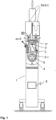
- the roller pump 5 has three rollers 5-1, 5-2, 5-3 which are rotatably mounted on an electric motor-driven rotor 7 and which are arranged along the Fig. 2 marked hose bed 6 of the peristaltic pump 5, and in doing so, the squeeze hose 4 is partially squeezed against a counter-bearing of the hose bed 6, so that when the rotor 7 rotates about its axis of rotation, an injection agent located in the squeeze hose 4 is conveyed in portions into the outlet line 9 against a back pressure in the outlet line 9.
- the injection device 1 has a control device 8 for controlling the roller pump 5 (and other components of the injection device 1).
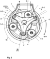
- FIG. 2 A perspective detailed view of the roller pump 5 is shown.
- the squeeze hose 4 runs over an angular range of approximately 260° - related to the rotational axis X of the roller pump 5 - between an inlet area 6-1 of the hose bed 6 and an outlet area 6-2 of the hose bed 6. Since the three rollers 5-1, 5-2, 5-3 are arranged evenly at an angular distance of 120° on the rotor 7, there are always at least two rollers between the inlet area 6-1 and the outlet area 6-2 of the hose bed 6, which press the squeeze hose 4 against the counter bearing of the squeeze the hose bed 6. The squeeze hose 4 is therefore always squeezed in at least two places during operation of the roller pump.
- the rotor 7 of the peristaltic pump rotates in one direction of rotation - in the illustration of Fig. 2 clockwise - so that the squeezed areas of the squeeze hose 4 move with the rollers 5-1, 5-2, 5-3 in the direction of rotation. Between each two squeezed areas, a liquid-tight hose section with a specific volume is formed, so that the injection medium contained therein is encapsulated between two rollers 5-1, 5-2, 5-3 and moved in the direction of rotation to the outlet area 6-2. If a roller 5-1 begins to lift off the hose bed 6 in the outlet area 6-2, the injection medium can be conveyed in the hose section against the dynamic pressure prevailing in the remaining part of the outlet line 9. Fig.
- pressure sensor 9-1 is arranged, which continuously measures the prevailing pressure p and transmits it to the control device 8.
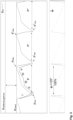
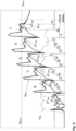
- a characteristic pressure curve p ist with several pressure cycles P, P', P" is shown as an example in Fig. 3 shown above in its temporal course.
- the pressure fluctuates between a pressure minimum p min at the beginning of the pressure cycle P, initially increases rapidly, then transitions into a region of moderate pressure increase and reaches a brief pressure plateau or pressure maximum p max , before the pressure drops rapidly and the next pressure cycle P' begins.
- the beginning of a printing cycle P correlates with the exit of the first roll 5-1 from the tube bed 6 in the outlet area 6-2, at which time a second roll 5-2 is in the Fig. 2 angular position marked with the reference symbol ⁇ 0.
- This second roller 5-2 represents the leading roller at this moment (and until the exit via the exit area 6-2) and reduces the size of the roller in front of it as it continues to rotate.
- the hose volume of the squeeze hose 4 continues to increase against a back pressure in the outlet line 9, which leads to the characteristic pressure increase.
- this second roller presses the hose bed 6 in the outlet area 6-2 ie at approximately an angular position which is Fig. 2 marked with the reference symbol ⁇ 120°
- the pinch of the squeeze tube 4 is released in this area, so that the volume increases almost abruptly up to the following third roller 5-3. This leads to the characteristic pressure drop at the end of a pressure cycle P.
- each of the three rollers 5-1, 5-2, 5-3 will therefore traverse the angular range designated ⁇ P between ⁇ 0° and ⁇ 120° once, causing a pressure cycle P.
- the pressure p should be kept as close as possible to the still permissible pressure limit p limit .
- the roller pump 5 should be controlled to a maximum volume flow Q max without exceeding the still permissible pressure limit p limit .
- the pressure limit p limit can therefore also be regarded as the (maximum) target pressure for the pressure p actual .
- a hazard pressure p Hazard pressure is shown, at which irreparable damage to the device or patient occurs. It must therefore be ensured that the hazard pressure p Hazard pressure is never exceeded.
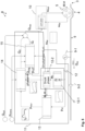
- control device 8 of this embodiment provides a control according to the Fig. 5
- the control system 8 comprises a second control circuit 10 for controlling the rotational (angular) speed ⁇ of the rotor 7 of the roller pump 5, the pump speed controller (PID controller), which receives the maximum volume flow Q max as a reference variable and converts this into a desired rotational (angular) speed ⁇ setpoint or a corresponding rotating field for controlling the roller pump.
- the actual rotational (angular) speed ⁇ actual is fed back as a measured variable, and any control deviation between the desired and actual rotational (angular) speed is minimized by feedback.
- a first control circuit 11 is connected upstream of the second control circuit 10, to which a target volume flow Q Soll and a permissible pressure limit p réelle are externally specified as reference variables.
- the feedback variables used are - unchanged - the target volume flow Q Soll , the pressure p ist measured in the outlet line 9 and the rotational angular velocity ⁇ ist of the rotor 7 measured at the roller pump 5. Roller pump 5 into the first control circuit 11. The measurement and feedback of an actual volume flow Q in the output line 9 can be omitted.
- the first control circuit 11 is designed as a discontinuous PID controller, which controls the controlled variable of the maximum volume flow Q max differently, depending on the pressure phase of a pressure cycle.
- the first control loop 11 comprises a pressure phase detection 12 with a pressure phase commutation detector 12-1 and a pressure phase switch 12-2, a pressure prediction 13 and a first control component 14 and a second control component 15.
- the pressure phase commutation detector 12-1 is used to detect the beginning of a pressure phase. To do so, it continuously compares the current pressure p actual with a reference value, namely a buffered pressure maximum p max of a previous pressure cycle P, and sets the beginning of a pressure cycle P to the time at which a pressure drop of more than 1/6 of the pressure p actual in the output line 9 compared to the buffered pressure maximum p max occurs. At this time, one of the rollers 5-1, 5-2, 5-3 of the roller pump 5 is approximately in the Fig. 2 angular position marked ⁇ 0° .
- Phase I is set as the current print phase.
- the pressure phase switch 12-2 switches or counts up the individual pressure phases II to V.
- the individual pressure phases or the beginning of the individual pressure phases are determined by the angle ⁇ i° .
- the pressure phase angle ⁇ i° is determined or approximated by temporal integration of the actual rotational angular velocity of the roller pump, starting from the reference value ⁇ 0° .
- the different pressure phases I to V are defined as follows: The beginning of the first pressure phase I is defined by a pressure drop of more than 1/6 compared to the pressure maximum of the previous pressure cycle. The beginning of the second pressure phase II is set at the time at or after a pressure increase is reliably achieved. This reliable pressure increase can be determined and recognized by a suitable pressure characteristic.
- the third pressure phase III corresponds to a first compression phase, The beginning of the first pressure phase is defined at a pressure phase angle of 45° (corresponding to a phase advance of 37.5% of the complete angular range ⁇ P ).
- a fourth pressure phase IV is defined at a pressure phase angle of 60° (phase advance of 50%). The beginning of the fifth pressure phase V is set at a pressure phase angle of 97.2° (phase advance of 81%).
- the individual printing phases I to V of several consecutive printing cycles P, P', P" are the Fig. 4 removable.
- the first control component 14 is activated via the pressure phase detection 12 when the current pressure cycle P is in the fourth pressure phase IV. In all other pressure phases (I to III and V), the first control component 14 is deactivated, i.e., set to zero.
- the predicted pressure p futur is continuously provided by the pressure forecast 13.
- the predicted pressure represents a prognosis for the expected pressure maximum in the current pressure cycle at the defined pressure phase angle.
- the predicted pressure p futur is in its temporal progression in Fig. 4 marked.
- prediction pressure and “predicted pressure” are synonymous.
- the second control component 15 is the proportional and integral element of the PID controller. It calculates a correction factor Q I , which is subtracted from the target flow rate Q Target and calculated using three components ⁇ , ⁇ , ⁇ :
- the maximum pressure p max of each pressure cycle is temporarily stored in a memory in the control device 8. Measurement errors of the pressure p actual can be smoothed using the mean value filter.
- the control device 8 thus designed allows the performance of the roller pump 5 or its rotational speed ⁇ to be regulated and adjusted in advance. Since the maximum volume flow Q max is calculated differently in pressure phases I to III and V than in pressure phase IV, this is a non-continuous control.
- a control response for the case of a clamped, fluid-tight outlet line 9 is shown in the diagram of the Fig. 6 with six consecutive pressure cycles A to F of the measured pressure p ist , the forecast pressure p futur calculated by the pressure forecast 13 and the associated pressure phases I to V of the individual pressure cycles A to F.
- the absolute pressure maximum p max increases continuously in each pressure cycle: p A max ⁇ p B max ⁇ p C max ⁇ p D max etc.
- the forecast pressure p futur exceeds the pressure limit p réelle for the first time in a fourth pressure phase IV in pressure cycle F.
- control device 8 of the embodiment according to Fig. 5 also a Fig. 5
- a control system (not shown) can be added, which increases or decreases the maximum target volume flow Q target depending on the phase progress.
- This control system manipulates the reference variable of the target volume flow Q target in such a way that the target volume flow Q target is increased by 30% to an increased target volume flow Q+ at the beginning of a printing cycle and reduced by 30% to a reduced target volume flow Q- towards the end of a printing cycle.
- the changed target volume flow Q target is held for a holding time of x-hold.
- the holding time x-hold can correspond to a certain phase progress, such as 25% or the duration of phase I. Due to the inverse adjustment to the increased or decreased target volume flow Q+ or Q- , the average target volume flow remains unchanged over a printing cycle P.
- the corresponding specification of the target volume flow is in Fig. 7A for a printing cycle P with the printing phases I to V. As the Fig. 7A As can be seen, the target volume flow Q Soll is suddenly increased to the volume flow Q + at the beginning of the pressure cycle P and then decreases linearly to the reduced target volume flow Q - .
- the thus changed command variable of the target volume flow Q Soll which is now variable over time over a pressure cycle P, is fed into the first control circuit 11.
- FIG. 7B a pressure curve is shown for several pressure cycles A to F, where the target volume flow Q Soll in the pressure cycles A to C and the beginning of the pressure cycle D according to the variable target volume flow Q Soll according to Fig. 7A was adjusted, and a constant target volume flow was specified in the subsequent pressure cycles.
- the pressure peaks p max of pressure cycles A, B and C can be reduced compared to the pressure peaks p max of pressure cycles D, E and F.
- a further effect of this control is that the motor power of the peristaltic pump 5 does not need to be abruptly reduced or even decelerated after the sudden pressure drop at the end of a pressure cycle P in order to keep the volume flow constant. This can save energy and reduce motor noise.
- the angular rotational speed ⁇ of the peristaltic pump 5 (minus measurement inaccuracies and the influence of the controlled system) has a comparable curve to the target volume flow Q target . It is therefore possible, instead of the target volume flow, to increase the angular rotational speed ⁇ target of the peristaltic pump depending on the pressure phase to an increased target speed ⁇ + at the beginning of a pressure cycle and/or to decrease it to a reduced target speed ⁇ - towards the end of the pressure cycle.
- the invention illustrated by way of example in the described embodiments enables a safer operation of a peristaltic pump with higher media throughput and lower pressure fluctuations.
- control device can also be used for other pumps with cyclically repeating pressure profiles, such as diaphragm pumps with an oscillating diaphragm, piston pumps with reciprocating pistons, sinusoidal pumps, or gear pumps.
- the control device is particularly suitable for applications where pressure relief valves are unsuitable due to their system-specific nature, as they discharge the medium.
Landscapes
- Engineering & Computer Science (AREA)
- Mechanical Engineering (AREA)
- General Engineering & Computer Science (AREA)
- Health & Medical Sciences (AREA)
- Hematology (AREA)
- Anesthesiology (AREA)
- Biomedical Technology (AREA)
- Heart & Thoracic Surgery (AREA)
- Vascular Medicine (AREA)
- Life Sciences & Earth Sciences (AREA)
- Animal Behavior & Ethology (AREA)
- General Health & Medical Sciences (AREA)
- Public Health (AREA)
- Veterinary Medicine (AREA)
- Infusion, Injection, And Reservoir Apparatuses (AREA)
- Reciprocating Pumps (AREA)
Claims (15)
- Dispositif de régulation (8) pour une pompe péristaltique (5) avec un tuyau à écraser (4) et des éléments d'acheminement (5-1, 5-2, 5-3) se déplaçant de façon cyclique pour l'acheminement d'un milieu guidé dans le tuyau à écraser (4) pendant un processus d'acheminement avec un débit volumétrique commandé jusque dans une conduite de distribution (9) reliée au tuyau à écraser (4), dans lequel les éléments d'acheminement (5-1, 5-2, 5-3) compriment le tuyau à écraser (4) de façon cyclique de sorte qu'un tracé de pression d'une pression (pist) se règle dans la conduite de distribution (9), lequel présente des cycles de pression (P) se renouvelant de façon cyclique, dans lequel chaque cycle de pression (P) présente un minimum de pression, une augmentation de pression, un maximum de pression et une baisse de pression, dans lequel le dispositif de régulation (8) régule une vitesse de la pompe péristaltique (5) de sorte qu'un débit volumétrique maximal (Qmax) soit atteint sans ce faisant dépasser une limite de pression (pGrenz) dans la conduite de distribution (9), dans lequel le dispositif de régulation (8) présente un premier circuit de régulation (11) pour la régulation du débit volumétrique maximal (Qmax) qui obtient un débit volumétrique de consigne (Qsoll) et la limite de pression (pGrenz) en tant que grandeurs de guidage, et est configuré pour l'exécution d'un procédé de régulation, qui est caractérisé en ce que
pour chaque cycle de pression (P) est calculée une pression anticipée (pfutur) pour une pression maximale à escompter à l'intérieur du cycle de pression (P) sur la base d'au moins la pression (pist) dans la conduite de distribution (9), et le débit volumétrique maximal (Qmax) est délimité en tenant compte de la pression anticipée (pfutur) de sorte que la pression (pist) dans la conduite de distribution (9) ne dépasse pas la limite de pression (pGrenz) dans le cycle de pression (P). - Dispositif de régulation (8) selon la revendication 1, caractérisé en ce que le premier circuit de régulation (11) comprend une détection de phase de pression (12) qui détecte la fin d'un cycle de pression précédent (P) et le début d'un cycle de pression suivant (P') à l'aide d'une grandeur caractéristique, en particulier d'une baisse de pression définie par rapport à un maximum de pression (pmax) du cycle de pression précédent (P), pour lancer la régulation du débit volumétrique maximal (Qmax) pour le cycle de pression suivant (P).
- Dispositif de régulation (8) selon l'une des revendications précédentes, caractérisé en ce que chaque cycle de pression (P) est divisé en phases de pression (I à V) se suivant de façon successive à l'aide de caractéristiques prédéfinies, en particulier d'une modification de pression et/ou d'un taux de modification de pression de la pression (pist), et la détection de phase de pression (12) détecte le début de chacune des phases de pression (I à V) soit à l'aide des caractéristiques prédéfinies, et en particulier le début d'une phase de pression à l'aide d'une modification de pression (Δp) de la pression (pist) et/ou d'un taux de modification de pression (dp/dt) de la pression (pist), et/ou soit à l'aide d'une position des éléments d'acheminement (5-1, 5-2, 5-3) de la pompe péristaltique (5), et la pression anticipée (pfutur) pour la régulation du débit volumétrique maximal (Qmax) dans le premier circuit de régulation (11) est utilisée uniquement dans des phases de pression déterminées et ignorée ou non utilisée dans d'autres phases de pression.
- Dispositif de régulation (8) selon la revendication 3, dans lequel une première phase de pression (I) est caractérisée par une perte de pression rapide, une deuxième phase de pression (II) est caractérisée par une augmentation de pression rapide, une troisième phase de pression (III) est caractérisée par une augmentation de pression plate, une quatrième phase de pression (IV) est caractérisée par une augmentation de pression modérée (IV) et une cinquième phase de pression (V) est caractérisée par un plateau de pression avec une pression essentiellement constante, et chaque phase de pression est détectée par la détection de phase de pression (12).
- Dispositif de régulation (8) selon la revendication 4, caractérisé en ce que dans le premier circuit de régulation (11) la pression anticipée (pfutur) pour la délimitation du débit volumétrique maximal (Qmax) est utilisée uniquement dans la quatrième phase de pression (IV), dans lequel la quatrième phase de pression (IV) se déplace de préférence et par approximation dans une plage du cycle de pression (P) de 50 % à 80 % d'un avancement de phase du cycle de pression (P).
- Dispositif de régulation (8) selon l'une des revendications 2 à 5, caractérisé en ce que, dans le processus de régulation, la pression anticipée (pfutur) est déterminée, en tant qu'extrapolation de préférence linéaire de l'augmentation de pression (pist) en cours, à un avancement de phase (φ87%) déterminé par calcul du cycle de pression (P).
- Dispositif de régulation (8) selon la revendication 6, caractérisé en ce que, dans le processus de régulation, l'avancement de phase (φ87%) déterminé par calcul auquel la pression anticipée (pfutur) est déterminée ne coïncide pas avec un avancement de phase (φ81%) effectif auquel survient la pression maximale (pmax) effective d'un cycle de pression (P).
- Dispositif de régulation (8) selon l'une des revendications précédentes, caractérisé en ce que le premier circuit de régulation (11) comprend un filtre à valeur moyenne qui ajuste le débit volumétrique maximal (Qmax) en fonction d'une pression maximale (pmax) d'un cycle de pression (P) précédant directement le cycle de pression (P) en cours, laquelle pression maximale est mise en cache dans le dispositif de régulation (8).
- Dispositif de régulation (8) selon l'une des revendications 3 à 8, caractérisé en ce que le premier circuit de régulation (11) est un régulateur PID avec un organe proportionnel (P), un organe intégral (I) et un organe différentiel (D), dans lequel l'organe différentiel est de préférence mis à zéro dans des phases de pression déterminées, en particulier dans la première phase de pression (I), la deuxième phase de pression (II), la troisième phase de pression (III) et la cinquième phase de pression (V).
- Dispositif de régulation (8) selon l'une des revendications précédentes, caractérisé en ce que le dispositif de régulation (8) comprend un pilotage pour le lissage de pointes de pression de la pression (pist) dans chacun des cycles de pression (P), dans lequel ce pilotage est configuré en tant qu'adaptateur de vitesse via lequel respectivement à un avancement déterminé du cycle de pression une vitesse de consigne (ωsoll) d'un élément d'acheminement (5-1, 5-2, 5-3) de la pompe péristaltique (5) par rapport à une vitesse de consigne moyenne est réduite, avant achèvement d'un cycle de pression (P), d'une quantité déterminée à une vitesse de consigne diminuée (ω-) et/ou est accrue, après achèvement d'un cycle de pression (P), d'une quantité déterminée à une vitesse de consigne accrue (ω+) et respectivement maintenue pendant une durée de maintien déterminée de sorte que la vitesse (ω) d'un élément d'acheminement (5-1, 5-2, 5-3) après achèvement d'un cycle de pression (P) soit accrue par à-coups de la quantité définie et ensuite réduite de façon linéaire jusqu'à la vitesse de consigne diminuée (ω-) de l'élément d'acheminement (5-1, 5-2, 5-3).
- Dispositif de régulation (8) selon l'une des revendications précédentes, caractérisé en ce que le processus d'acheminement comprend plus d'un, en particulier plus de 5 et de façon particulièrement préférée plus de 10 cycles de pression.
- Pompe péristaltique sous la forme d'une pompe à galets (5) avec un rotor (7) rotatif et un dispositif de régulation (8) selon l'une des revendications précédentes,dans laquelle les éléments d'acheminement (5-1, 5-2, 5-3) pour l'écrasement d'un tuyau à écraser (4) sont conçus en tant que galets agencés contre un rotor (7), dans laquelle le tuyau à écraser (4) est monté le long d'un lit de tuyau (6) avec une zone de pénétration (6-1) et une zone d'évacuation (6-2) et, lorsque le rotor (7) tourne, les éléments d'acheminement (5-1, 5-2, 5-3) écrasent respectivement de façon étanche aux fluides l'une derrière l'autre une section du tuyau à écraser (4) lors de l'entrée des éléments d'acheminement (5-1, 5-2, 5-3) dans le lit de tuyau (6) à hauteur de la zone de pénétration (6-1) et jusqu'à la sortie des éléments d'acheminement (5-1, 5-2, 5-3) hors du lit de tuyau (6) à hauteur de la zone d'évacuation (6-2), et ce faisant acheminent le milieu se trouvant dans le tuyau à écraser (4) jusque dans la conduite de distribution (9) dans la direction de rotation et à l'encontre d'une pression dynamique dans la conduite de distribution (9),dans laquelle un volume respectif, du tuyau à écraser (4), se trouvant avant la zone d'évacuation (6-2) est comprimé depuis un volume maximal vers un volume minimal jusqu'à ce qu'un élément d'acheminement (5-1, 5-2, 5-3) sorte du lit de tuyau (6) à hauteur de la zone d'évacuation (6-2) et ce faisant libère la section du tuyau à écraser (4) écrasée par cet élément d'acheminement (5-1, 5-2, 5-3) et ainsi le volume, du tuyau à écraser (4), se trouvant avant la zone d'évacuation (6-2) est augmenté depuis le volume minimal vers le volume maximal, dans laquelle respectivement une réduction de volume et une augmentation de volume ultérieure du volume se trouvant avant la zone d'évacuation (6-2) constituent ensemble un cycle de pression (P) complet,et la pompe à galets (5) présente n éléments d'acheminement (5-1, 5-2, 5-3) répartis régulièrement et de préférence radialement de sorte que la pompe à galets (5) exécute n courses de pompe avec n cycles de pression (P) lors d'une rotation complète du rotor (7) de 360°,et chaque phase de pression (I à V) d'un cycle de pression (P) correspond essentiellement à une plage angulaire déterminée d'une position angulaire (φ) d'un élément d'acheminement (5-1, 5-2, 5-3).
- Pompe péristaltique selon la revendication 12, caractérisée en ce que le début d'au moins une phase de pression (I à V) d'un cycle de pression (P) est indirectement déterminé par la détection de phase de pression (12) via une position angulaire (φ) d'un élément d'acheminement (5-1, 5-2, 5-3).
- Appareil d'injection (1) pour l'injection d'un moyen d'injection dans un corps animal ou humain au moyen d'une pompe péristaltique conçue en tant que pompe à galets (5), caractérisé en ce que l'appareil d'injection (1) contient une pompe péristaltique (5) selon l'une des revendications 12 ou 13.
- Procédé de régulation pour une pompe péristaltique (5) avec un tuyau à écraser (4) et des éléments d'acheminement (5-1, 5-2, 5-3) se déplaçant de façon cyclique pour l'acheminement d'un milieu guidé dans le tuyau à écraser (4) pendant un processus d'acheminement avec un débit volumétrique commandé jusque dans une conduite de distribution (9) reliée au tuyau à écraser (4), dans lequel les éléments d'acheminement (5-1, 5-2, 5-3) compriment le tuyau à écraser (4) de façon cyclique de sorte qu'un tracé de pression d'une pression (pist) se règle dans la conduite de distribution (9), lequel présente des cycles de pression (P) se renouvelant de façon cyclique, dans lequel chaque cycle de pression présente un minimum de pression, une augmentation de pression, un maximum de pression et une baisse de pression, dans lequel le procédé de régulation régule une vitesse de la pompe péristaltique (5) de sorte qu'un débit volumétrique maximal (Qmax) soit atteint sans ce faisant dépasser une limite de pression (pGrenz) dans la conduite de distribution (9), dans lequel le procédé de régulation présente un premier circuit de régulation (11) pour la régulation du débit volumétrique maximal (Qmax) qui obtient un débit volumétrique de consigne (Qsoll) et la limite de pression (pGrenz) en tant que grandeurs de guidage, dans lequel le procédé est caractérisé en ce que
pour chaque cycle de pression (P) est calculée une pression anticipée (pfutur) pour une pression maximale (pmax) à escompter à l'intérieur du cycle de pression (P) sur la base de la pression (pist) dans la conduite de distribution (9), et le débit volumétrique maximal (Qmax) est délimité en tenant compte de la pression anticipée (pfutur) de sorte que la pression (pist) dans la conduite de distribution ne dépasse pas la limite de pression (pGrenz) dans le cycle de pression (P).
Applications Claiming Priority (1)
| Application Number | Priority Date | Filing Date | Title |
|---|---|---|---|
| DE102022107119.7A DE102022107119A1 (de) | 2022-03-25 | 2022-03-25 | Regeleinrichtung für eine Peristaltikpumpe, Peristaltikpumpe, Injektionsgerät und Verfahren zur Steuerung einer Peristaltikpumpe |
Publications (2)
| Publication Number | Publication Date |
|---|---|
| EP4249751A1 EP4249751A1 (fr) | 2023-09-27 |
| EP4249751B1 true EP4249751B1 (fr) | 2025-05-07 |
Family
ID=85510847
Family Applications (1)
| Application Number | Title | Priority Date | Filing Date |
|---|---|---|---|
| EP23160540.3A Active EP4249751B1 (fr) | 2022-03-25 | 2023-03-07 | Dispositif de régulation pour pompe péristaltique, pompe péristaltique, appareil d'injection et procédé de commande de pompe péristaltique |
Country Status (6)
| Country | Link |
|---|---|
| US (1) | US20230302218A1 (fr) |
| EP (1) | EP4249751B1 (fr) |
| CN (1) | CN116803442A (fr) |
| BR (1) | BR102023005411A2 (fr) |
| DE (1) | DE102022107119A1 (fr) |
| ES (1) | ES3034415T3 (fr) |
Families Citing this family (1)
| Publication number | Priority date | Publication date | Assignee | Title |
|---|---|---|---|---|
| CN120053812B (zh) * | 2025-04-27 | 2025-07-15 | 华东交通大学 | 输液流速控制方法、系统、可读存储介质及计算机 |
Family Cites Families (8)
| Publication number | Priority date | Publication date | Assignee | Title |
|---|---|---|---|---|
| US6673033B1 (en) | 1999-11-24 | 2004-01-06 | Medrad, Inc. | Injectors, injector systems and injector control |
| DE102012007412B4 (de) * | 2012-04-16 | 2023-09-28 | Fresenius Medical Care Deutschland Gmbh | Verfahren und Vorrichtungen zur Modulation des Arbeitspunktes von Flüssigkeitspumpen in medizinischen Behandlungsvorrichtungen |
| SE537628C2 (sv) * | 2013-11-08 | 2015-08-18 | Bonvisi Ab | Anordning för irrigation och insufflation med blodtrycksberoende tryckstyrning |
| DE102013113387A1 (de) | 2013-12-03 | 2015-06-03 | Ulrich Gmbh & Co. Kg | Injektor zur Injektion eines Fluids und Verfahren zur Steuerung eines Injektors |
| CN104739520B (zh) * | 2015-04-20 | 2017-06-27 | 匡仁锐 | 医用灌注泵的控制方法及使用该方法的系统 |
| JP7086926B2 (ja) | 2016-07-18 | 2022-06-20 | ネクステージ メディカル インコーポレイテッド | フローバランシングの装置、方法、及びシステム |
| WO2020157723A2 (fr) | 2019-01-31 | 2020-08-06 | Jaime Zacharias | Pompe d'aspiration à hauteur d'aspiration pouvant être commandée |
| SE546314C2 (en) | 2020-10-19 | 2024-10-01 | Thoragen Ab | Improved body drainage apparatus |
-
2022
- 2022-03-25 DE DE102022107119.7A patent/DE102022107119A1/de active Pending
-
2023
- 2023-03-07 EP EP23160540.3A patent/EP4249751B1/fr active Active
- 2023-03-07 ES ES23160540T patent/ES3034415T3/es active Active
- 2023-03-23 BR BR102023005411-0A patent/BR102023005411A2/pt unknown
- 2023-03-27 CN CN202310305899.7A patent/CN116803442A/zh active Pending
- 2023-03-27 US US18/126,643 patent/US20230302218A1/en active Pending
Also Published As
| Publication number | Publication date |
|---|---|
| CN116803442A (zh) | 2023-09-26 |
| BR102023005411A2 (pt) | 2023-10-03 |
| EP4249751A1 (fr) | 2023-09-27 |
| ES3034415T3 (en) | 2025-08-18 |
| DE102022107119A1 (de) | 2023-09-28 |
| US20230302218A1 (en) | 2023-09-28 |
Similar Documents
| Publication | Publication Date | Title |
|---|---|---|
| EP3061473B1 (fr) | Pompe a galets tubulaire dotee de rouleaux de pression a angle variable | |
| EP2550454B1 (fr) | Procédé de commande d'une pompe doseuse | |
| DE60023937T2 (de) | Vorrichtung zur kompensation von druckunterschieden zwischen ventilen in kasseten vom typ iv pumpen | |
| EP3568596B1 (fr) | Régulation de la géométrie d'écartement dans une pompe à vis excentrique | |
| DE3239190C2 (fr) | ||
| DE68906744T2 (de) | Ein in-line-Infiltrationsdetektionsgerät und Methode. | |
| DE102010053903B4 (de) | Pumpenrotor | |
| EP2881129B1 (fr) | Injecteur destiné à l'injection d'un fluide et procédé de commande d'un injecteur | |
| DE3786224T2 (de) | Pumpvorrichtung mit niedriger Pulsation. | |
| EP2362102B1 (fr) | Agrégat de pompes de dosage | |
| EP2600917B1 (fr) | Dispositif muni d'une pompe péristaltique | |
| WO2013156138A2 (fr) | Procédés et dispositifs de modulation du point de travail de pompes à liquide dans des dispositifs de traitement médicaux | |
| EP2860399A1 (fr) | Procédé de fonctionnement d'un dispositif d'alimentation qui sollicite un canal avec un liquide, et dispositif d'alimentation | |
| EP3648812B1 (fr) | Système de pompage et appareil de dialyse | |
| DE3923457A1 (de) | Vorrichtung zum injizieren von fluessigkeiten | |
| EP3250829A1 (fr) | Pompe à vis excentrée munie d'un système de réglage automatique et procédé d'ajustement | |
| EP2040964A1 (fr) | Système de freinage de véhicule avec un accumulateur basse pression | |
| EP4249751B1 (fr) | Dispositif de régulation pour pompe péristaltique, pompe péristaltique, appareil d'injection et procédé de commande de pompe péristaltique | |
| EP2651467B1 (fr) | Système de traitement de sang extracorporel | |
| EP0484717B1 (fr) | Pompe à tuyau | |
| DE202022101585U1 (de) | Regeleinrichtung und Regelungssystem für eine Peristaltikpumpe, Peristaltikpumpe mit einer solchen Regeleinrichtung sowie Injektionsgerät mit einer solchen Peristaltikpumpe | |
| EP3610902A1 (fr) | Système de pompes destiné à pomper un liquide et procédé de fonctionnement du système de pompes | |
| EP2362100B2 (fr) | Agrégat de pompes de dosage et procédé de commande d'un agrégat de pompes de dosage | |
| DE102006043597A1 (de) | Verfahren zur Betriebsüberwachung einer Exzenterschneckenpumpe, sowie Exzenterschneckenpumpe zur Durchführung dieses Verfahrens | |
| DE102023128576A1 (de) | Kreiselradumpe mit ausfahrbaren Schaufeln |
Legal Events
| Date | Code | Title | Description |
|---|---|---|---|
| PUAI | Public reference made under article 153(3) epc to a published international application that has entered the european phase |
Free format text: ORIGINAL CODE: 0009012 |
|
| STAA | Information on the status of an ep patent application or granted ep patent |
Free format text: STATUS: THE APPLICATION HAS BEEN PUBLISHED |
|
| AK | Designated contracting states |
Kind code of ref document: A1 Designated state(s): AL AT BE BG CH CY CZ DE DK EE ES FI FR GB GR HR HU IE IS IT LI LT LU LV MC ME MK MT NL NO PL PT RO RS SE SI SK SM TR |
|
| STAA | Information on the status of an ep patent application or granted ep patent |
Free format text: STATUS: REQUEST FOR EXAMINATION WAS MADE |
|
| 17P | Request for examination filed |
Effective date: 20240327 |
|
| RBV | Designated contracting states (corrected) |
Designated state(s): AL AT BE BG CH CY CZ DE DK EE ES FI FR GB GR HR HU IE IS IT LI LT LU LV MC ME MK MT NL NO PL PT RO RS SE SI SK SM TR |
|
| GRAP | Despatch of communication of intention to grant a patent |
Free format text: ORIGINAL CODE: EPIDOSNIGR1 |
|
| STAA | Information on the status of an ep patent application or granted ep patent |
Free format text: STATUS: GRANT OF PATENT IS INTENDED |
|
| INTG | Intention to grant announced |
Effective date: 20241113 |
|
| GRAJ | Information related to disapproval of communication of intention to grant by the applicant or resumption of examination proceedings by the epo deleted |
Free format text: ORIGINAL CODE: EPIDOSDIGR1 |
|
| STAA | Information on the status of an ep patent application or granted ep patent |
Free format text: STATUS: REQUEST FOR EXAMINATION WAS MADE |
|
| INTC | Intention to grant announced (deleted) | ||
| GRAP | Despatch of communication of intention to grant a patent |
Free format text: ORIGINAL CODE: EPIDOSNIGR1 |
|
| STAA | Information on the status of an ep patent application or granted ep patent |
Free format text: STATUS: GRANT OF PATENT IS INTENDED |
|
| GRAS | Grant fee paid |
Free format text: ORIGINAL CODE: EPIDOSNIGR3 |
|
| INTG | Intention to grant announced |
Effective date: 20250205 |
|
| GRAA | (expected) grant |
Free format text: ORIGINAL CODE: 0009210 |
|
| STAA | Information on the status of an ep patent application or granted ep patent |
Free format text: STATUS: THE PATENT HAS BEEN GRANTED |
|
| AK | Designated contracting states |
Kind code of ref document: B1 Designated state(s): AL AT BE BG CH CY CZ DE DK EE ES FI FR GB GR HR HU IE IS IT LI LT LU LV MC ME MK MT NL NO PL PT RO RS SE SI SK SM TR |
|
| REG | Reference to a national code |
Ref country code: GB Ref legal event code: FG4D Free format text: NOT ENGLISH |
|
| REG | Reference to a national code |
Ref country code: CH Ref legal event code: EP |
|
| REG | Reference to a national code |
Ref country code: DE Ref legal event code: R096 Ref document number: 502023000933 Country of ref document: DE |
|
| REG | Reference to a national code |
Ref country code: IE Ref legal event code: FG4D Free format text: LANGUAGE OF EP DOCUMENT: GERMAN |
|
| REG | Reference to a national code |
Ref country code: ES Ref legal event code: FG2A Ref document number: 3034415 Country of ref document: ES Kind code of ref document: T3 Effective date: 20250818 |
|
| REG | Reference to a national code |
Ref country code: NL Ref legal event code: MP Effective date: 20250507 |
|
| PG25 | Lapsed in a contracting state [announced via postgrant information from national office to epo] |
Ref country code: PT Free format text: LAPSE BECAUSE OF FAILURE TO SUBMIT A TRANSLATION OF THE DESCRIPTION OR TO PAY THE FEE WITHIN THE PRESCRIBED TIME-LIMIT Effective date: 20250908 Ref country code: FI Free format text: LAPSE BECAUSE OF FAILURE TO SUBMIT A TRANSLATION OF THE DESCRIPTION OR TO PAY THE FEE WITHIN THE PRESCRIBED TIME-LIMIT Effective date: 20250507 |
|
| REG | Reference to a national code |
Ref country code: LT Ref legal event code: MG9D |
|
| PG25 | Lapsed in a contracting state [announced via postgrant information from national office to epo] |
Ref country code: NO Free format text: LAPSE BECAUSE OF FAILURE TO SUBMIT A TRANSLATION OF THE DESCRIPTION OR TO PAY THE FEE WITHIN THE PRESCRIBED TIME-LIMIT Effective date: 20250807 Ref country code: GR Free format text: LAPSE BECAUSE OF FAILURE TO SUBMIT A TRANSLATION OF THE DESCRIPTION OR TO PAY THE FEE WITHIN THE PRESCRIBED TIME-LIMIT Effective date: 20250808 |
|
| PG25 | Lapsed in a contracting state [announced via postgrant information from national office to epo] |
Ref country code: NL Free format text: LAPSE BECAUSE OF FAILURE TO SUBMIT A TRANSLATION OF THE DESCRIPTION OR TO PAY THE FEE WITHIN THE PRESCRIBED TIME-LIMIT Effective date: 20250507 Ref country code: PL Free format text: LAPSE BECAUSE OF FAILURE TO SUBMIT A TRANSLATION OF THE DESCRIPTION OR TO PAY THE FEE WITHIN THE PRESCRIBED TIME-LIMIT Effective date: 20250507 |
|
| PG25 | Lapsed in a contracting state [announced via postgrant information from national office to epo] |
Ref country code: BG Free format text: LAPSE BECAUSE OF FAILURE TO SUBMIT A TRANSLATION OF THE DESCRIPTION OR TO PAY THE FEE WITHIN THE PRESCRIBED TIME-LIMIT Effective date: 20250507 |
|
| PG25 | Lapsed in a contracting state [announced via postgrant information from national office to epo] |
Ref country code: HR Free format text: LAPSE BECAUSE OF FAILURE TO SUBMIT A TRANSLATION OF THE DESCRIPTION OR TO PAY THE FEE WITHIN THE PRESCRIBED TIME-LIMIT Effective date: 20250507 |
|
| PG25 | Lapsed in a contracting state [announced via postgrant information from national office to epo] |
Ref country code: RS Free format text: LAPSE BECAUSE OF FAILURE TO SUBMIT A TRANSLATION OF THE DESCRIPTION OR TO PAY THE FEE WITHIN THE PRESCRIBED TIME-LIMIT Effective date: 20250807 |
|
| PG25 | Lapsed in a contracting state [announced via postgrant information from national office to epo] |
Ref country code: IS Free format text: LAPSE BECAUSE OF FAILURE TO SUBMIT A TRANSLATION OF THE DESCRIPTION OR TO PAY THE FEE WITHIN THE PRESCRIBED TIME-LIMIT Effective date: 20250907 |
|
| PG25 | Lapsed in a contracting state [announced via postgrant information from national office to epo] |
Ref country code: LV Free format text: LAPSE BECAUSE OF FAILURE TO SUBMIT A TRANSLATION OF THE DESCRIPTION OR TO PAY THE FEE WITHIN THE PRESCRIBED TIME-LIMIT Effective date: 20250507 |
|
| PG25 | Lapsed in a contracting state [announced via postgrant information from national office to epo] |
Ref country code: DK Free format text: LAPSE BECAUSE OF FAILURE TO SUBMIT A TRANSLATION OF THE DESCRIPTION OR TO PAY THE FEE WITHIN THE PRESCRIBED TIME-LIMIT Effective date: 20250507 Ref country code: SM Free format text: LAPSE BECAUSE OF FAILURE TO SUBMIT A TRANSLATION OF THE DESCRIPTION OR TO PAY THE FEE WITHIN THE PRESCRIBED TIME-LIMIT Effective date: 20250507 |
|
| PG25 | Lapsed in a contracting state [announced via postgrant information from national office to epo] |
Ref country code: CZ Free format text: LAPSE BECAUSE OF FAILURE TO SUBMIT A TRANSLATION OF THE DESCRIPTION OR TO PAY THE FEE WITHIN THE PRESCRIBED TIME-LIMIT Effective date: 20250507 |
|
| PG25 | Lapsed in a contracting state [announced via postgrant information from national office to epo] |
Ref country code: EE Free format text: LAPSE BECAUSE OF FAILURE TO SUBMIT A TRANSLATION OF THE DESCRIPTION OR TO PAY THE FEE WITHIN THE PRESCRIBED TIME-LIMIT Effective date: 20250507 |
|
| PG25 | Lapsed in a contracting state [announced via postgrant information from national office to epo] |
Ref country code: SK Free format text: LAPSE BECAUSE OF FAILURE TO SUBMIT A TRANSLATION OF THE DESCRIPTION OR TO PAY THE FEE WITHIN THE PRESCRIBED TIME-LIMIT Effective date: 20250507 |