EP4249751A1 - Dispositif de régulation pour pompe péristaltique, pompe péristaltique, appareil d'injection et procédé de commande de pompe péristaltique - Google Patents
Dispositif de régulation pour pompe péristaltique, pompe péristaltique, appareil d'injection et procédé de commande de pompe péristaltique Download PDFInfo
- Publication number
- EP4249751A1 EP4249751A1 EP23160540.3A EP23160540A EP4249751A1 EP 4249751 A1 EP4249751 A1 EP 4249751A1 EP 23160540 A EP23160540 A EP 23160540A EP 4249751 A1 EP4249751 A1 EP 4249751A1
- Authority
- EP
- European Patent Office
- Prior art keywords
- pressure
- cycle
- phase
- printing
- volume flow
- Prior art date
- Legal status (The legal status is an assumption and is not a legal conclusion. Google has not performed a legal analysis and makes no representation as to the accuracy of the status listed.)
- Pending
Links
- 230000002572 peristaltic effect Effects 0.000 title claims abstract description 48
- 238000002347 injection Methods 0.000 title claims description 50
- 239000007924 injection Substances 0.000 title claims description 50
- 238000000034 method Methods 0.000 title claims description 30
- 230000001105 regulatory effect Effects 0.000 claims abstract description 13
- 238000001514 detection method Methods 0.000 claims description 21
- 239000003795 chemical substances by application Substances 0.000 claims description 13
- 230000008569 process Effects 0.000 claims description 13
- 230000008859 change Effects 0.000 claims description 9
- 238000013213 extrapolation Methods 0.000 claims description 5
- 241001465754 Metazoa Species 0.000 claims description 3
- 238000011038 discontinuous diafiltration by volume reduction Methods 0.000 claims description 2
- 238000009499 grossing Methods 0.000 claims description 2
- 238000012937 correction Methods 0.000 description 9
- 238000010586 diagram Methods 0.000 description 6
- 239000002872 contrast media Substances 0.000 description 4
- 230000008901 benefit Effects 0.000 description 3
- 230000033228 biological regulation Effects 0.000 description 3
- 230000001276 controlling effect Effects 0.000 description 3
- 230000007423 decrease Effects 0.000 description 3
- 238000005259 measurement Methods 0.000 description 3
- 230000010349 pulsation Effects 0.000 description 3
- 238000005086 pumping Methods 0.000 description 3
- 230000002123 temporal effect Effects 0.000 description 3
- 238000004364 calculation method Methods 0.000 description 2
- 230000001419 dependent effect Effects 0.000 description 2
- 230000010354 integration Effects 0.000 description 2
- 239000007788 liquid Substances 0.000 description 2
- 230000035484 reaction time Effects 0.000 description 2
- 230000004044 response Effects 0.000 description 2
- 230000007704 transition Effects 0.000 description 2
- FAPWRFPIFSIZLT-UHFFFAOYSA-M Sodium chloride Chemical compound [Na+].[Cl-] FAPWRFPIFSIZLT-UHFFFAOYSA-M 0.000 description 1
- 230000003321 amplification Effects 0.000 description 1
- 238000013459 approach Methods 0.000 description 1
- 239000000872 buffer Substances 0.000 description 1
- 238000005352 clarification Methods 0.000 description 1
- 230000006835 compression Effects 0.000 description 1
- 238000007906 compression Methods 0.000 description 1
- 238000002591 computed tomography Methods 0.000 description 1
- 125000004122 cyclic group Chemical group 0.000 description 1
- 230000003247 decreasing effect Effects 0.000 description 1
- 238000011161 development Methods 0.000 description 1
- 230000000694 effects Effects 0.000 description 1
- 230000006870 function Effects 0.000 description 1
- 238000003384 imaging method Methods 0.000 description 1
- 230000006872 improvement Effects 0.000 description 1
- 238000001990 intravenous administration Methods 0.000 description 1
- 238000010253 intravenous injection Methods 0.000 description 1
- 238000004519 manufacturing process Methods 0.000 description 1
- 239000000463 material Substances 0.000 description 1
- 239000012528 membrane Substances 0.000 description 1
- 238000003199 nucleic acid amplification method Methods 0.000 description 1
- 230000010355 oscillation Effects 0.000 description 1
- 230000002028 premature Effects 0.000 description 1
- 230000009467 reduction Effects 0.000 description 1
- 238000004904 shortening Methods 0.000 description 1
- 230000003068 static effect Effects 0.000 description 1
- 238000003325 tomography Methods 0.000 description 1
Images


Classifications
-
- A—HUMAN NECESSITIES
- A61—MEDICAL OR VETERINARY SCIENCE; HYGIENE
- A61M—DEVICES FOR INTRODUCING MEDIA INTO, OR ONTO, THE BODY; DEVICES FOR TRANSDUCING BODY MEDIA OR FOR TAKING MEDIA FROM THE BODY; DEVICES FOR PRODUCING OR ENDING SLEEP OR STUPOR
- A61M5/00—Devices for bringing media into the body in a subcutaneous, intra-vascular or intramuscular way; Accessories therefor, e.g. filling or cleaning devices, arm-rests
- A61M5/14—Infusion devices, e.g. infusing by gravity; Blood infusion; Accessories therefor
- A61M5/142—Pressure infusion, e.g. using pumps
- A61M5/14212—Pumping with an aspiration and an expulsion action
- A61M5/14232—Roller pumps
-
- F—MECHANICAL ENGINEERING; LIGHTING; HEATING; WEAPONS; BLASTING
- F04—POSITIVE - DISPLACEMENT MACHINES FOR LIQUIDS; PUMPS FOR LIQUIDS OR ELASTIC FLUIDS
- F04B—POSITIVE-DISPLACEMENT MACHINES FOR LIQUIDS; PUMPS
- F04B43/00—Machines, pumps, or pumping installations having flexible working members
- F04B43/12—Machines, pumps, or pumping installations having flexible working members having peristaltic action
- F04B43/1253—Machines, pumps, or pumping installations having flexible working members having peristaltic action by using two or more rollers as squeezing elements, the rollers moving on an arc of a circle during squeezing
-
- F—MECHANICAL ENGINEERING; LIGHTING; HEATING; WEAPONS; BLASTING
- F04—POSITIVE - DISPLACEMENT MACHINES FOR LIQUIDS; PUMPS FOR LIQUIDS OR ELASTIC FLUIDS
- F04B—POSITIVE-DISPLACEMENT MACHINES FOR LIQUIDS; PUMPS
- F04B49/00—Control, e.g. of pump delivery, or pump pressure of, or safety measures for, machines, pumps, or pumping installations, not otherwise provided for, or of interest apart from, groups F04B1/00 - F04B47/00
- F04B49/08—Regulating by delivery pressure
-
- F—MECHANICAL ENGINEERING; LIGHTING; HEATING; WEAPONS; BLASTING
- F04—POSITIVE - DISPLACEMENT MACHINES FOR LIQUIDS; PUMPS FOR LIQUIDS OR ELASTIC FLUIDS
- F04B—POSITIVE-DISPLACEMENT MACHINES FOR LIQUIDS; PUMPS
- F04B49/00—Control, e.g. of pump delivery, or pump pressure of, or safety measures for, machines, pumps, or pumping installations, not otherwise provided for, or of interest apart from, groups F04B1/00 - F04B47/00
- F04B49/20—Control, e.g. of pump delivery, or pump pressure of, or safety measures for, machines, pumps, or pumping installations, not otherwise provided for, or of interest apart from, groups F04B1/00 - F04B47/00 by changing the driving speed
-
- A—HUMAN NECESSITIES
- A61—MEDICAL OR VETERINARY SCIENCE; HYGIENE
- A61M—DEVICES FOR INTRODUCING MEDIA INTO, OR ONTO, THE BODY; DEVICES FOR TRANSDUCING BODY MEDIA OR FOR TAKING MEDIA FROM THE BODY; DEVICES FOR PRODUCING OR ENDING SLEEP OR STUPOR
- A61M5/00—Devices for bringing media into the body in a subcutaneous, intra-vascular or intramuscular way; Accessories therefor, e.g. filling or cleaning devices, arm-rests
- A61M5/007—Devices for bringing media into the body in a subcutaneous, intra-vascular or intramuscular way; Accessories therefor, e.g. filling or cleaning devices, arm-rests for contrast media
Definitions
- the invention relates to a control device for a peristaltic pump according to the preamble of claim 1, a peristaltic pump with such a control device, an injection device with such a peristaltic pump and a method for controlling a peristaltic pump.
- Injection devices are medical devices with which liquid injection agents (medium) can be introduced into a human or animal body in a controlled manner using a pump device.
- the injection agent can be, for example, a contrast agent for increasing the contrast in an imaging method, such as computer tomography or magnetic resonance tomography.
- a contrast agent for increasing the contrast in an imaging method, such as computer tomography or magnetic resonance tomography.
- known injection devices provide controls or regulations that switch off the injection device or its pumping device when a permissible pressure limit (maximum target pressure), which is below a defined dangerous pressure, is exceeded.
- pressure maxima can occur that are only briefly and slightly above the pressure limit and therefore lead to the pump device being switched off unnecessarily or the injection process being aborted. This prolongs the injection process and unnecessarily increases the total injected volume of injectable.
- US 6,673,033 B1 proposed to define an intermediate pressure threshold, if it is exceeded, the performance of a pumping device is initially throttled, and to only switch off the pumping device when the pressure in a hose line of an injector rises above a pressure limit despite the throttled performance.
- a temporal criterion is used as the criterion for terminating an injection process Integral of the pressure curve from the time a pressure limit is exceeded should be used as a benchmark for terminating the injection process, so that short-term pressure peaks can be tolerated and a short-term exceeding of the pressure limit does not lead to an immediate termination of the injection process.
- a peristaltic pump with an oscillating pressure curve pressure pulsation
- a peristaltic pump with such a control device an injection device with such a peristaltic pump and a control method in which safety intervals are reduced and a predetermined pressure limit is closer can be brought to a dangerous pressure without increasing the risk of harm to the patient and/or the material of the injection device.
- pressure pulsations should be reduced.
- control device of claim 1 the peristaltic pump according to claim 12, an injection device according to claim 14 and a control method according to claim 15.
- the control device is used to control a peristaltic pump with a squeeze hose and cyclically moving conveying elements for conveying a medium guided in the squeeze hose during a conveying process with a controlled volume flow into an output line connected to the squeeze hose.
- the conveying elements compress the squeeze tube cyclically, so that a pressure is established in the output line with a pressure curve that has cyclically repeating pressure cycles.
- Each printing cycle can be defined in such a way that it extends, for example, from a pressure minimum through a pressure increase to a pressure maximum and then drops again to a pressure minimum of a subsequent printing cycle.
- the control device regulates a speed of the peristaltic pump - in the case of a roller pump, this can be an angular speed of a conveying element act - in such a way that a maximum volume flow is achieved without a pressure limit in the output line being exceeded.
- the pressure limit can be a desired, still permissible target pressure.
- the control device has at least a first control circuit for regulating the maximum volume flow. This receives a target volume flow and the pressure limit as externally specified reference variables.
- the control device is set up to carry out a control method in which a prediction pressure for an expected maximum pressure within the pressure cycle is calculated for each pressure cycle based on at least the pressure in the output line and the maximum volume flow is limited, taking the prediction pressure into account, so that the pressure in the output line does not exceed the pressure limit in the printing cycle.
- the first control loop expediently records the current pressure in the output line as a feedback variable, based on which a control part of the control loop controls the maximum volume flow in a predictive manner.
- the speed of the peristaltic pump can be adjusted early and proactively and, in particular, reduced if the pressure limit is threatened to be exceeded. Since reaction times are extended by the pressure forecast, safety reserves increase. Pressure limits that are still permissible can then be brought closer to critical pressure values, such as a danger pressure, which in turn means higher volume flows and thus, for example, a shortening of the injection duration for a specific injection volume. Since the importance of fast-reacting mechanics becomes less important with predictive control, more inert components can also be used for the peristaltic pump, which makes the production of the peristaltic pump cheaper. Calibration of the control process is not necessary if the control device is designed appropriately.
- the first control circuit includes a printing phase detection, through which the end of a previous printing cycle and the beginning of a subsequent printing cycle are recognized.
- the detection can take place based on a characteristic size of the pressure curve in the output line, in particular a defined pressure drop compared to a pressure maximum of the previous printing cycle.
- the start of a printing cycle can, for example, be defined at the point in time a pressure drop compared to the (absolute) pressure maximum of the previous pressure cycle by more than a certain relative amount, for example by at least 1/6, 1 ⁇ 4 or 1/3 or - regardless of the previous pressure maximum - by an absolute amount, for example at least 2 bar, occurs.
- the pressure drop is advantageously chosen to be so large that this pressure drop only occurs once towards the end of a printing cycle. The occurrence of this pressure drop is then sufficiently robust to indicate the start of a subsequent pressure cycle. Should a typical printing cycle have larger pressure fluctuations, larger pressure drops and/or incremental counters can be used as an alternative, which count the number of pressure drops by a certain minimum amount in order to detect the start of a subsequent printing cycle.
- each pressure cycle is divided into successive pressure phases based on predefined characteristics and the pressure phase detection detects the beginning of the individual pressure phases, the prediction pressure being used to control the maximum volume flow in the first control loop only in certain pressure phases and ignored or not used in other printing phases.
- the regulation is therefore discontinuous.
- An advantage of such a pressure phase-dependent control is that the pressure prediction can be used precisely in the pressure phases in which the development of the pressure in the output line is dynamic and the pressure limit can be exceeded comparatively suddenly, so that the maximum volume flow is conservative in these pressure phases is regulated, while it can be regulated more aggressively in other pressure phases, since a sudden exceeding of the pressure limit is not to be expected in these other pressure phases.
- a further advantage is that different controls can be implemented for different pressure phases, for example by switching on or switching off additional control loops that are superimposed on the first control loop and/or by changing the control parameters of the first control loop, such as the gain factors used therein or the like.
- the aforementioned predefined characteristics may be absolute or relative pressure changes and/or an absolute or relative pressure change rate of the pressure in the output line.
- the predefined characteristics do not necessarily have to be point values. For example, it is possible to choose moving averages over specific time periods, such as 0.1, 0.2 or 0.5 seconds.
- the recognition of the individual pressure phases by the pressure phase detection can be done based on the predefined characteristics. Alternatively, however, individual pressure phases can also be recognized based on a position of the conveying elements of the peristaltic pump through the pressure phase detection, since the positions of the conveying elements - as explained in more detail below - correlate with the individual pressure phases. It is also possible to combine the detection based on predefined characteristics and a position determination of the conveying elements for the printing phase detection, be it at the same time in order to make the printing phase detection of individual printing phases redundant or be it in order to detect individual printing phases based on the defined characteristics and other printing phases based on the position of the Determine conveying elements.
- the pressure phase detection is preferably designed redundantly to increase reliability. This makes it possible to reduce susceptibility to errors and, in particular, requirements for the reliability of individual components, and thus component costs.
- the printing cycle is characterized by five successive printing phases, with a first printing phase characterized by a rapid pressure loss, a second printing phase characterized by a rapid pressure increase, a third printing phase characterized by a flat pressure increase, a fourth printing phase characterized by a moderate pressure increase and a fifth printing phase is characterized by a pressure plateau with essentially constant pressure, and each pressure phase is recognized by the pressure phase detection.
- a division of a pressure cycle is a good approximation for pressure cycles in injection devices for intravenous injection of, for example, contrast agents.
- the static and dynamic pressure resistances in the output line (and the adjoining lines) are responsible for the individual pressure phases, which arise in particular from opening and closing check valves, throttles, the mass inertia of the medium to be pumped and other influences.
- the printing phases can also be defined differently than in the example above.
- the prediction pressure for controlling the maximum volume flow is only used in the fourth pressure phase, i.e. the pressure phase before the pressure plateau with the (absolute) pressure maximum within the pressure cycle.
- the fourth printing phase is advantageously defined in a range that ranges from approximately 50% to approximately 80% of a phase progression of the printing cycle.
- Phase progression is understood to mean the printing cycle in time resolution, i.e. the printing cycle begins at 0% phase progression - this corresponds, for example, to a pressure minimum - and ends at 100% - this then corresponds to the pressure minimum of the subsequent printing cycle.
- the forecast pressure is 'connected' to the first control loop in the fourth pressure phase to calculate the maximum volume flow, and is otherwise 'switched off', it is a discontinuous controller.
- the prediction pressure By limiting the use of the prediction pressure in this way, a complex calculation of the prediction pressure in the other printing phases can be dispensed with.
- the prediction pressure can be achieved via a linear extrapolation of the current pressure increase in the output line to a specific (calculated) phase progress, which is preferably in the range of 80% to 95% of the total phase progress and, for example, at 80%, 90% or 95% of the total phase progress and in particular 87% of the total phase progress can be determined.
- a specific (calculated) phase progress which is preferably in the range of 80% to 95% of the total phase progress and, for example, at 80%, 90% or 95% of the total phase progress and in particular 87% of the total phase progress can be determined.
- the specific (calculated) phase progress that is used to determine the forecast pressure is expediently chosen to be fixed and is, for example, a constant 87% of the total phase progress.
- This particular phase progression can - but does not have to - correspond to the real phase progression at which real pressure maxima occur in the pressure cycles. Actual pressure maxima can therefore occur at actual phase progressions that lie before or behind the specific (calculated) phase progression of, in the example, 87% of the total phase progression.
- the specific phase progress is preferably selected and set mathematically so that prediction pressures are achieved that correspond as accurately as possible to the actual pressure maxima successive print cycles.
- the specific (computational) phase progression to which the forecast pressure is extrapolated can be shifted to the real phase progression at which a real pressure maximum occurs, if this results in better forecast pressures.
- the control device controls a roller pump.
- Roller pumps have the advantage that there are no changes in direction, which is why roller pumps are particularly suitable for precise dosing of injection boluses in injection devices. Since the medium conveyed in roller pumps is conveyed in a squeeze hose, there is no direct contact between the medium conveyed and the pump in roller pumps, which is advantageous for hygienic reasons. Furthermore, the squeeze hose can be easily replaced.
- the invention therefore also relates to a roller pump with a rotatable rotor, a plurality of conveying elements for squeezing a squeeze hose, which are designed as rollers (squeeze rollers) arranged on the rotor, the squeeze hose being mounted along a hose bed with an inlet area and an outlet area and
- the conveying elements successively squeeze a section of the squeeze hose in a fluid-tight manner when the conveying elements enter the hose bed at the level of the inlet area and until the conveying elements exit the hose bed at the level of the outlet area and thereby a medium located in the squeeze hose in the direction of rotation in the opposite direction Promote dynamic pressure in an output line connected to the squeeze hose into the output line, the roller pump containing a control device according to the invention.
- a volume of the squeeze tube located in front of the outlet area is compressed from a maximum volume to a minimum volume until a conveying element emerges from the hose bed at the level of the outlet area, releasing the section of the squeeze tube squeezed by this conveying element and thus that located in front of the outlet area Volume of the squeeze tube increased from the minimum volume to the maximum volume.
- the volume reduction and volume increase of the volume in front of the outlet area together represent a complete printing cycle.
- the roller pump also has n preferably radially uniformly distributed conveying elements, so that the roller pump carries out n pump strokes with n pressure cycles when the rotor rotates completely through 360°.
- the number of role elements is, for example, three.
- each conveying element is only involved in a printing cycle in a certain angular section, namely in the angular section in which the conveying element represents the "leading" role in relation to the outlet area or the output line, the angular position of the conveying element correlates with the phase progress in this angular section of the printing cycle.
- individual angular ranges of the angular position of the conveying elements within the angular section also correlate with individual printing phases of a printing cycle.
- the pressure phase to be determined based on the angular position of one of the conveying elements, in particular a 'leading' conveying element.
- the printing phase detection of the control device determines the start of at least one printing phase of a printing cycle via an angular position of a conveying element.
- the angular position is expediently determined indirectly, for example via the temporal integration of the angular velocity of the conveying elements or the rotor of the roller pump.
- the angular velocity of the rotor is usually available directly via a roller pump control unit.
- an absolute angular position of the leading conveying element can be approximated via a pressure drop by a minimum amount.
- the first control circuit comprises a mean value filter which adapts the maximum volume flow depending on a maximum pressure temporarily stored in the control device of a pressure cycle immediately preceding the current pressure cycle. This allows errors in the measurement of the pressure in the output line to be compensated for.
- the mean value filter can dampen the oscillation behavior of the control loop and, in particular, prevent or at least reduce overshoot of the controlled variable.
- the previous measured maximum pressure is used as a ratio of the measured maximum pressure to the pressure limit (target pressure) is returned to the first control loop and a new target volume flow is set based on this. A deviation between the actual maximum pressure and the pressure limit (target pressure) can be reduced with each cycle.
- the first control circuit is advantageously a PID controller with a proportional element, an integral element and a differential element.
- a PID controller enables the controlled variable to approach the reference variables quickly and accurately.
- the prediction pressure for regulating the maximum volume flow is preferably processed in the differential element.
- further feedback variables for example a rate of change in a rotational speed of a rotor of a peristaltic pump and/or a rate of change in the volume flow, can also be taken into account in the differential element.
- the differential element is advantageously set to 0 in certain pressure phases. In this way, advance control intervention can be switched off if necessary.
- control device can include a control for smoothing pressure peaks in pressure cycles.
- the control is advantageously a speed adapter.
- the speed adapter is preferably set up in such a way that at a certain progress in the pressure cycle, a target speed of a conveying element of the peristaltic pump is reduced by a certain amount to a reduced target speed compared to an average target speed before the completion of a printing cycle and/or after completion of a Printing cycle is increased by a certain amount to an increased target speed and is held for a certain holding period.
- the speed of the conveying elements increases suddenly to the increased target speed and is then reduced linearly to the reduced target speed of the conveying element after the holding period. This allows load peaks to be reduced.
- All holding periods can be the same or different lengths.
- the increase and decrease in the target speed is expediently of the same magnitude.
- the speed of the peristaltic pump can, for example, be increased or decreased as a percentage by a predetermined proportion of the average target speed, the change in speed preferably being between 20% and 40% of the average target speed and in particular at 20%, 30% or 40% can be above or below the average target speed.
- the control is superimposed on the first control loop via a speed adapter.
- the change caused by the control can be taken into account as a modified reference variable of the target rotational speed in the first control loop.
- the rotational speed and the target volume flow are viewed as being directly proportional to one another and therefore interchangeable.
- the influences of the first control loop with the pressure prediction and the influences of the control reinforce each other, so that the control quality of the control device can be increased disproportionately.
- the delivery process of a peristaltic pump regularly includes more than one, in particular more than five and particularly preferably more than ten pressure cycles.
- an injection device for injecting an injection agent into an animal or human body using a peristaltic pump designed as a roller pump which has a control device according to the invention to regulate the roller pump.
- a control device to regulate the roller pump.
- a control method for a peristaltic pump which has a squeeze hose and cyclically moving conveying elements for conveying a medium guided in the squeeze hose during a conveying process with a controlled volume flow into an output line connected to the squeeze hose, the conveying elements cyclically compress the squeeze hose so that a pressure curve of a pressure is established in the output line which has cyclically repeating pressure cycles, each pressure cycle having a pressure minimum, a pressure increase, a pressure maximum and a pressure drop, the control method regulating a speed of the peristaltic pump in such a way, that a maximum volume flow is achieved without exceeding a pressure limit in the output line, the control method comprising a first control loop for regulating the maximum volume flow, which receives a target volume flow and the pressure limit as reference variables, and a prediction pressure for each pressure cycle The expected maximum pressure within the printing cycle is calculated based on the pressure in the output line. The maximum volume flow is then limited, taking the forecast pressure into account, so that
- Fig. 1 shows an injection device 1 for intravenous administration of an injection agent.
- the injection device 1 has a base body mounted on rollers, at the upper end of which several injection agent containers 2a, 2b, 2c are arranged. Contrast medium and a saline solution are stored in the injection medium containers 2a, 2b, 2c.
- the injection agent containers 2a, 2b, 2c are connected to a squeeze hose 4 via an inlet line 3.
- the squeeze tube 4 is inserted into the tube bed 6 of a roller pump 5 and connected on the output side to an output line 9, which in turn can be connected to the bloodstream of a patient via an adjoining patient tube (not shown) via a catheter.
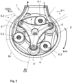
- the roller pump 5 has three rollers 5-1, 5-2, 5-3 rotatably mounted on an electric motor-driven rotor 7, which run along the in Fig. 2 marked hose bed 6 of the peristaltic pump 5 are guided, and the squeeze hose 4 is partially counteracted squeeze a counter bearing of the hose bed 6, so that when the rotor 7 rotates about its axis of rotation, an injection agent located in the squeeze hose 4 is conveyed into the output line 9 in portions against a dynamic pressure in the output line 9.
- the injection device 1 has a control device 8 for controlling the roller pump 5 (and other components of the injection device 1).
- a perspective detailed view of the roller pump 5 is shown.
- the squeeze hose 4 runs over an angular range of approximately 260 ° - based on the axis of rotation 1, 5-2, 5-3 are arranged evenly at an angular distance of 120 ° on the rotor 7, there are always at least two rollers between the inlet area 6-1 and the outlet area 6-2 of the hose bed 6, which hold the squeeze hose 4 against the counter bearing of the hose bed 6.
- the squeeze hose 4 is therefore always squeezed in at least two places during operation of the roller pump.
- the rotor 7 of the peristaltic pump rotates in a direction of rotation - in the illustration Fig. 2 clockwise - so that the squeezed areas of the squeeze hose 4 move in the direction of rotation with the rollers 5-1, 5-2, 5-3.
- a liquid-tight tube section with a certain volume is formed between two squeezed areas, so that the injection agent contained therein is encapsulated between two rollers 5-1, 5-2, 5-3 and is moved in the direction of rotation up to the outlet area 6-2. If a roller 5-1 begins to lift off the hose bed 6 in the outlet area 6-2, the injection agent can be conveyed in the hose section against the dynamic pressure prevailing in the remaining part of the output line 9.
- Pressure sensor 9-1 shown is arranged, which continuously measures the pressure p ist prevailing therein and forwards it to the control device 8.
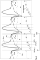
- a characteristic pressure curve p is with several pressure cycles P, P ', P "is exemplary in Fig. 3 shown above in its chronological progression.
- P the pressure fluctuates between a pressure minimum p min at the beginning of the pressure cycle P, initially increases quickly, then goes into a region with a moderate pressure increase and reaches a short-term pressure plateau or pressure maximum p max before the pressure drops rapidly and the next print cycle P ⁇ begins.
- the start of a printing cycle P correlates with an exit of the first roller 5-1 from the hose bed 6 in the outlet area 6-2, at which point a second roller 5-2 is in the in Fig. 2 with the reference symbol ⁇ 0 is located.
- This second roller 5-2 represents the leading role at this moment (and until it exits via the exit area 6-2) and, with further rotation, further reduces the hose volume of the squeeze hose 4 in front of it against a dynamic pressure in the output line 9, which leads to the characteristic increase in pressure.
- this second role the hose bed 6 in the outlet area 6-2, ie approximately at an angular position that is in the Fig. 2 is provided with the reference symbol ⁇ 120 ° , the crushing of the pinch hose 4 is canceled in this area, so that the volume increases almost suddenly up to the subsequent third roller 5-3. This leads to the characteristic pressure drop at the end of a pressure cycle P.
- each of the three rollers 5-1, 5-2, 5-3 will therefore pass through the angular range between ⁇ 0° and ⁇ 120° , designated ⁇ P , and cause a printing cycle P.
- a time course of the pressure phase angle ⁇ i° in is shown Fig. 3 shown below.
- the roller pump 5 is to be regulated to a maximum volume flow Q max without the still permissible pressure limit p limit being exceeded.
- the pressure limit p limit can therefore also be understood as the (maximum) target pressure for the pressure p is .
- Above the limit p limit is in Fig. 3 Additionally, a hazard pressure p hazard pressure is shown, at which irreparable damage to the device or patient occurs. It must therefore be ensured that the hazard pressure p hazard pressure is not exceeded under any circumstances.
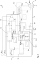
- control device 8 of this exemplary embodiment sees a control according to in Fig. 5 the control scheme shown.
- the control device 8 includes a second control circuit 10 for regulating the Rotational (angular) speed ⁇ of the rotor 7 of the roller pump 5, the pump speed controller (Pump Speed PID controller), which receives the maximum volume flow Q max as a reference variable and converts this into a target rotational (angular) speed ⁇ target or a corresponding rotating field converted to control the roller pump.
- the actual actual rotational (angular) speed ⁇ is fed back as a measured variable and a control deviation between the target and actual rotational (angular) speed is minimized via feedback.
- the second control circuit 10 is preceded by a first control circuit 11, to which a target volume flow Q target and a permissible pressure limit p limit are externally specified as reference variables.
- the feedback variables - unchanged - are the target volume flow Q Soll , the pressure p measured in the output line 9 and the angular speed ⁇ ist of the rotor 7 of the roller pump 5 measured on the roller pump 5 in the first control circuit 11.
- the measurement and feedback of an actual volume flow Q in the output line 9 can be dispensed with.
- the first control circuit 11 is constructed as a discontinuous PID controller, which regulates the controlled variable of the maximum volume flow Q max differently, depending on which pressure phase a pressure cycle is in.
- the first control circuit 11 includes a pressure phase detection 12 with a pressure phase commutation detector 12-1 and a pressure phase switch 12-2, a pressure prediction 13 and a first control component 14 and a second control component 15.
- the printing phase commutation detector 12-1 is used to detect the start of a printing phase. For this purpose, it continuously compares the current pressure p ist with a reference value, namely a temporarily stored pressure maximum p max of a previous printing cycle P, and sets the start of a printing cycle P at the point in time at which a pressure drop in the pressure p is in the output line 9 of more than 1/6 compared to the buffered pressure maximum p max occurs. At this point, one of the rollers 5-1, 5-2, 5-3 of the roller pump 5 is approximately in the in Fig. 2 Angle position marked with ⁇ 0° .
- Phase I is set as the current printing phase.
- the pressure phase switch 12-2 switches or counts up the individual pressure phases II to V.
- the individual pressure phases or the start of the individual pressure phases are determined via the angle ⁇ i° .
- the pressure phase angle ⁇ i ° is in turn detected or approximated - starting from the reference value ⁇ 0 ° - via a temporal integration of the actual angular speed of the roller pump.
- the different printing phases I to V are defined as follows:
- the start of the first printing phase I is defined by a pressure drop of more than 1/6 compared to the pressure maximum of the previous printing cycle.
- the start of the second pressure phase II is set at the point in time at or after a pressure increase occurs safely. This safe pressure increase can be determined by a suitable characteristic number of the pressure curve and can be recognized from this.
- the third pressure phase III corresponds to a first compression phase, the beginning of which is defined at a pressure phase angle of 45° (this corresponds to a phase progression of 37.5% of the complete angular range ⁇ P ).
- a fourth printing phase IV is defined at a printing phase angle of 60° (phase progression of 50%).
- the start of the fifth printing phase V is set at a printing phase angle of 97.2° (phase progress of 81%).
- the individual printing phases I to V of several consecutive printing cycles P, P', P" are the Fig. 4 removable.
- the first control component 14 is activated via the printing phase detection 12 when the current printing cycle P is in the fourth printing phase IV. In all other printing phases (I to III and V), the first control component 14 is deactivated, i.e. set to zero.
- the first control component 14 is the differential element of the PID controller.
- the predicted pressure p future is continuously made available by the pressure forecast 13.
- the forecast pressure represents a forecast for the expected pressure maximum in the current pressure cycle at the defined pressure phase angle.
- the predicted pressure p future is in its time course in Fig. 4 drawn.
- the second control component 15 is the proportional and integral element of the PID controller.
- a correction factor Q I is calculated in it, which is deducted from the target volume flow Q Soll and is calculated using three components ⁇ , ⁇ , ⁇ :
- the maximum pressure p max of each pressure cycle is temporarily stored in a memory in the control device 8. Measuring errors of the pressure p ist can be smoothed out using the mean value filter.
- the power of the roller pump 5 or its rotational speed ⁇ can be regulated and adjusted in advance via the control device 8 designed in this way. Since the maximum volume flow Q max is calculated differently in pressure phases I to III and V than in pressure phase IV, it is a non-continuous control.
- a control response for the case of a disconnected, fluid-impermeable output line 9 is shown in the diagram Fig. 6 with six consecutive printing cycles A to F of measured pressure p is , the prediction pressure p future calculated by the pressure prediction 13 and the associated pressure phases I to V of the individual pressure cycles A to F.
- the absolute pressure maximum p max increases steadily in each pressure cycle: p A max ⁇ p B max ⁇ p C max ⁇ p D max etc.
- the prediction pressure p future exceeds the pressure limit p limit in a fourth pressure phase IV for the first time in pressure cycle F.
- the other excesses of the prediction pressure p future beyond the pressure limit p limit in other phases, for example in pressure cycle D in pressure phase II, are irrelevant, since the control device 8 takes the prediction pressure p future into account only in the pressure phase IV via the control component 14.
- every fourth printing phase IV begins at a printing phase angle of 60° (or a phase progression of 50%)
- the maximum target volume flow Q max in the printing cycle F and thus also the rotational speed ⁇ is with the onset of the printing phase IV in the printing cycle F reduced by the control device 8.
- the throttling of the rotational speed ⁇ is at the beginning of phase IV Fig. 6 easy to see.
- the pressure limit p limit will not be exceeded due to the sufficient lead time between detection of an imminent overshoot of the pressure limit p limit and the occurrence of the pressure maximum p F max ⁇ p limit .
- the control device 8 of the exemplary embodiment can be used Fig. 5 also about an in Fig. 5 Control, not shown, can be added, which increases or decreases the maximum target volume flow Q target depending on the phase progress.
- This control manipulates the reference variable of the target volume flow Q target in such a way that the target volume flow Q target is increased by 30% to an increased target volume flow Q+ at the beginning of a printing cycle and by 30% to a reduced target volume flow towards the end of a printing cycle Q_ is reduced.
- the changed target volume flow Q target is held for a holding period of x-hold.
- the holding period x-hold can correspond to a certain phase progress, such as 25% or the duration of phase I. Due to the opposite adjustment to the increased or reduced target volume flow Q + or Q_, the average target volume flow remains unchanged over a pressure cycle P.
- the corresponding specification of the target volume flow is in Fig. 7A for a printing cycle P with the printing phases I to V. Again Fig. 7A can be seen, the target volume flow Q is suddenly raised to the volume flow Q+ at the beginning of the pressure cycle P and then decreases linearly to the reduced target volume flow Q_.
- the thus changed reference variable of the target volume flow Q Soll which is now variable over time over a pressure cycle P, is fed into the first control circuit 11.
- FIG. 7B a pressure curve is shown for several pressure cycles A to F, whereby the target volume flow Q target in the pressure cycles A to C and the start of the pressure cycle D corresponding to the variable target volume flow Q target Fig. 7A was adjusted and a constant target volume flow was specified in the subsequent pressure cycles.
- the pressure peaks p max of the pressure cycles A, B and C can be reduced compared to the pressure peaks p max of the pressure cycles D, E and F.
- Another effect of this control is that motor power of the peristaltic pump 5 does not have to be suddenly reduced or even braked after the sudden pressure drop at the end of a pressure cycle P in order to keep the volume flow constant. This can save energy and reduce engine noise.
- the angular rotation speed ⁇ is of the peristaltic pump 5 (minus measurement inaccuracies and the influence of the controlled system) has a comparable course to the target volume flow Q Soll . It is therefore possible, instead of the target volume flow, to also increase the angular speed ⁇ target of the peristaltic pump , depending on the pressure phase, to an increased target speed ⁇ + at the beginning of a pressure cycle and / or to reduce it to a reduced target speed ⁇ - towards the end of the printing cycle.
- the invention shown as an example in the exemplary embodiments described enables safer operation of a peristaltic pump with higher media throughput and lower pressure fluctuations.
- control device can also be used for other pumps with cyclically repeating pressure curves, such as diaphragm pumps with an oscillating membrane, piston pumps with pistons moving back and forth, sine pumps or gear pumps.
- the control device is particularly suitable for applications in which pressure relief valves are unsuitable for system reasons because medium is drained through them.
Applications Claiming Priority (1)
| Application Number | Priority Date | Filing Date | Title |
|---|---|---|---|
| DE102022107119.7A DE102022107119A1 (de) | 2022-03-25 | 2022-03-25 | Regeleinrichtung für eine Peristaltikpumpe, Peristaltikpumpe, Injektionsgerät und Verfahren zur Steuerung einer Peristaltikpumpe |
Publications (1)
| Publication Number | Publication Date |
|---|---|
| EP4249751A1 true EP4249751A1 (fr) | 2023-09-27 |
Family
ID=85510847
Family Applications (1)
| Application Number | Title | Priority Date | Filing Date |
|---|---|---|---|
| EP23160540.3A Pending EP4249751A1 (fr) | 2022-03-25 | 2023-03-07 | Dispositif de régulation pour pompe péristaltique, pompe péristaltique, appareil d'injection et procédé de commande de pompe péristaltique |
Country Status (5)
| Country | Link |
|---|---|
| US (1) | US20230302218A1 (fr) |
| EP (1) | EP4249751A1 (fr) |
| CN (1) | CN116803442A (fr) |
| BR (1) | BR102023005411A2 (fr) |
| DE (1) | DE102022107119A1 (fr) |
Citations (5)
| Publication number | Priority date | Publication date | Assignee | Title |
|---|---|---|---|---|
| US6673033B1 (en) | 1999-11-24 | 2004-01-06 | Medrad, Inc. | Injectors, injector systems and injector control |
| DE102013113387A1 (de) | 2013-12-03 | 2015-06-03 | Ulrich Gmbh & Co. Kg | Injektor zur Injektion eines Fluids und Verfahren zur Steuerung eines Injektors |
| CN104739520A (zh) * | 2015-04-20 | 2015-07-01 | 匡仁锐 | 医用灌注泵的控制方法及使用该方法的系统 |
| SE537628C2 (sv) * | 2013-11-08 | 2015-08-18 | Bonvisi Ab | Anordning för irrigation och insufflation med blodtrycksberoende tryckstyrning |
| US9567992B2 (en) * | 2012-04-16 | 2017-02-14 | Fresenius Medical Care Deutschland Gmbh | Methods and devices for modulation of the operating point of liquid pumps in medical treatment devices |
Family Cites Families (3)
| Publication number | Priority date | Publication date | Assignee | Title |
|---|---|---|---|---|
| GB2570050B (en) | 2016-07-18 | 2020-01-01 | Nxstage Medical Inc | Apparatus for controlling fluid flow in a circuit |
| WO2020157723A2 (fr) | 2019-01-31 | 2020-08-06 | Jaime Zacharias | Pompe d'aspiration à hauteur d'aspiration pouvant être commandée |
| SE2051209A1 (en) | 2020-10-19 | 2022-04-20 | Thoragen Ab | Improved body drainage apparatus |
-
2022
- 2022-03-25 DE DE102022107119.7A patent/DE102022107119A1/de active Pending
-
2023
- 2023-03-07 EP EP23160540.3A patent/EP4249751A1/fr active Pending
- 2023-03-23 BR BR102023005411-0A patent/BR102023005411A2/pt unknown
- 2023-03-27 US US18/126,643 patent/US20230302218A1/en active Pending
- 2023-03-27 CN CN202310305899.7A patent/CN116803442A/zh active Pending
Patent Citations (5)
| Publication number | Priority date | Publication date | Assignee | Title |
|---|---|---|---|---|
| US6673033B1 (en) | 1999-11-24 | 2004-01-06 | Medrad, Inc. | Injectors, injector systems and injector control |
| US9567992B2 (en) * | 2012-04-16 | 2017-02-14 | Fresenius Medical Care Deutschland Gmbh | Methods and devices for modulation of the operating point of liquid pumps in medical treatment devices |
| SE537628C2 (sv) * | 2013-11-08 | 2015-08-18 | Bonvisi Ab | Anordning för irrigation och insufflation med blodtrycksberoende tryckstyrning |
| DE102013113387A1 (de) | 2013-12-03 | 2015-06-03 | Ulrich Gmbh & Co. Kg | Injektor zur Injektion eines Fluids und Verfahren zur Steuerung eines Injektors |
| CN104739520A (zh) * | 2015-04-20 | 2015-07-01 | 匡仁锐 | 医用灌注泵的控制方法及使用该方法的系统 |
Also Published As
| Publication number | Publication date |
|---|---|
| BR102023005411A2 (pt) | 2023-10-03 |
| US20230302218A1 (en) | 2023-09-28 |
| CN116803442A (zh) | 2023-09-26 |
| DE102022107119A1 (de) | 2023-09-28 |
Similar Documents
| Publication | Publication Date | Title |
|---|---|---|
| EP2881129B1 (fr) | Injecteur destiné à l'injection d'un fluide et procédé de commande d'un injecteur | |
| EP3061473B1 (fr) | Pompe a galets tubulaire dotee de rouleaux de pression a angle variable | |
| DE102010053903B4 (de) | Pumpenrotor | |
| EP2600917B1 (fr) | Dispositif muni d'une pompe péristaltique | |
| EP2550454B1 (fr) | Procédé de commande d'une pompe doseuse | |
| EP2469094B1 (fr) | Procédé de fonctionnement d'un agrégat de pompes doubles ou multipompes | |
| EP3250829B1 (fr) | Pompe à vis excentrée munie d'un système de réglage automatique et procédé d'ajustement | |
| EP2860399A1 (fr) | Procédé de fonctionnement d'un dispositif d'alimentation qui sollicite un canal avec un liquide, et dispositif d'alimentation | |
| EP0985419A1 (fr) | Contrôle de pression d'un fluide, perfusé ou injecté, administré par dose | |
| WO2013156138A2 (fr) | Procédés et dispositifs de modulation du point de travail de pompes à liquide dans des dispositifs de traitement médicaux | |
| EP3568596B1 (fr) | Régulation de la géométrie d'écartement dans une pompe à vis excentrique | |
| DE3923457C2 (fr) | ||
| WO1994029595A1 (fr) | Regulateur a plusieurs etages pour pompes a lubrifiant a debit continuellement variable | |
| WO2011101118A1 (fr) | Groupe motopompe de dosage | |
| EP2651467B1 (fr) | Système de traitement de sang extracorporel | |
| EP2040964A1 (fr) | Système de freinage de véhicule avec un accumulateur basse pression | |
| DE202011052114U1 (de) | Innenzahnradpumpe | |
| EP3648812A1 (fr) | Système de pompage, appareil de dialyse et procédé pour faire fonctionner un système de pompage | |
| EP4249751A1 (fr) | Dispositif de régulation pour pompe péristaltique, pompe péristaltique, appareil d'injection et procédé de commande de pompe péristaltique | |
| DE202022101585U1 (de) | Regeleinrichtung und Regelungssystem für eine Peristaltikpumpe, Peristaltikpumpe mit einer solchen Regeleinrichtung sowie Injektionsgerät mit einer solchen Peristaltikpumpe | |
| EP1308415A2 (fr) | Dispositif de levage hydraulique en particulier pour chariots industriels alimentés par batterie et son procédé de commande | |
| EP1427931A1 (fr) | Procede, programme informatique, appareil de commande et/ou de regulation pour actionner un moteur a combustion interne et systeme de carburant pour moteur a combustion interne | |
| AT504416A2 (de) | Verfahren und vorrichtung für ein einspritzen bei einer spritzgiessmaschine | |
| DE112009001698B4 (de) | Anordnung und Verfahren zur unterbrechungsfreien Versorgung eines Hydrauliksystems mit einem Fluid | |
| WO2011038706A1 (fr) | Commande hydraulique |
Legal Events
| Date | Code | Title | Description |
|---|---|---|---|
| PUAI | Public reference made under article 153(3) epc to a published international application that has entered the european phase |
Free format text: ORIGINAL CODE: 0009012 |
|
| STAA | Information on the status of an ep patent application or granted ep patent |
Free format text: STATUS: THE APPLICATION HAS BEEN PUBLISHED |
|
| AK | Designated contracting states |
Kind code of ref document: A1 Designated state(s): AL AT BE BG CH CY CZ DE DK EE ES FI FR GB GR HR HU IE IS IT LI LT LU LV MC ME MK MT NL NO PL PT RO RS SE SI SK SM TR |
|
| STAA | Information on the status of an ep patent application or granted ep patent |
Free format text: STATUS: REQUEST FOR EXAMINATION WAS MADE |