EP4249691A1 - Sanitärarmatur mit einem schlauch - Google Patents
Sanitärarmatur mit einem schlauch Download PDFInfo
- Publication number
- EP4249691A1 EP4249691A1 EP23162700.1A EP23162700A EP4249691A1 EP 4249691 A1 EP4249691 A1 EP 4249691A1 EP 23162700 A EP23162700 A EP 23162700A EP 4249691 A1 EP4249691 A1 EP 4249691A1
- Authority
- EP
- European Patent Office
- Prior art keywords
- lumen
- adapter
- liquid
- outlet
- inlet
- Prior art date
- Legal status (The legal status is an assumption and is not a legal conclusion. Google has not performed a legal analysis and makes no representation as to the accuracy of the status listed.)
- Granted
Links
Images

Classifications
-
- E—FIXED CONSTRUCTIONS
- E03—WATER SUPPLY; SEWERAGE
- E03C—DOMESTIC PLUMBING INSTALLATIONS FOR FRESH WATER OR WASTE WATER; SINKS
- E03C1/00—Domestic plumbing installations for fresh water or waste water; Sinks
- E03C1/02—Plumbing installations for fresh water
- E03C1/04—Water-basin installations specially adapted to wash-basins or baths
- E03C1/0404—Constructional or functional features of the spout
Definitions
- the present invention relates to a sanitary fitting that can be used in particular in connection with sinks and/or washbasins.
- Sanitary fittings are used on sinks, sinks, bathtubs and/or showers to provide a liquid, especially water, as needed.
- sanitary fittings can have a housing with an outlet and an outlet opening for the liquid.
- the housing of the sanitary fitting can be attached to a support, for example a worktop or a sink or sink.
- sanitary fittings can have a mixing valve or a mixing cartridge through which cold water and hot water can be mixed to form mixed water with a desired mixed water temperature.
- Sanitary fittings are also known with which various liquids, for example mixed water, carbonated liquid, flavored liquid, filtered liquid, cooled liquid and/or hot water, can be dispensed.
- various liquids for example mixed water, carbonated liquid, flavored liquid, filtered liquid, cooled liquid and/or hot water
- several liquid lines are required which extend parallel to one another through the fitting housing and/or the outlet. This results in a high space requirement for the liquid lines, which limits the freedom of design of the fitting housings or outlets.
- the individual liquids can be dispensed via separate outlet openings of the sanitary fittings or a mousseur of the sanitary fittings so that they do not come into contact with one another before being dispensed or cannot mix with one another.
- a correspondingly high number of outlet openings must be provided or a mousseur must have a correspondingly high number of separate liquid channels, which increases the complexity of the sanitary fitting or the mousseur.
- the object of the invention is therefore to at least partially solve the problems described with reference to the prior art and in particular to provide a sanitary fitting through which different or more liquids can be directed to the outlet opening with less space and which has less complexity.
- the sanitary fitting serves in particular to provide liquids, such as water in particular, to sinks and/or sinks as needed.
- the sanitary fitting includes a fitting housing, which in particular can consist at least partially of plastic and/or (cast) metal, such as brass.
- the fitting housing is on one Carrier, for example a worktop, the sink or washbasin, can be attached and / or has a (protruding or branching) outlet that is rigidly or movably connected to the fitting housing.
- the outlet can be at least partially tubular and/or has at least one outlet opening.
- the at least one outlet opening can be designed, for example, in the manner of a jet former or mousseur.
- the tube has at least a first lumen for guiding a first liquid from a first liquid source to the outlet opening, a second lumen for guiding a second liquid from a second liquid source to the outlet opening, and a third lumen for guiding a third liquid from a third liquid source to the outlet opening on.
- the tube can have at least one further lumen for guiding at least one further liquid from at least one further liquid source.
- the lumens are in particular each a (tubular) liquid channel which extends through the tube from a first longitudinal end of the tube to a second longitudinal end of the tube.
- the first longitudinal end of the hose can be connected to the first liquid source, second liquid source and third liquid source (and possibly the at least one further liquid source).
- the first longitudinal end of the hose can be connected to a distribution device for the at least one first liquid source, second liquid source and third liquid source (and possibly for the at least one further liquid source).
- the distributor device can be connected to the first liquid source, second liquid source and third liquid source (and possibly the at least one further liquid source).
- the distributor device can be arranged outside the fitting housing and/or the outlet.
- the individual lumens run in particular parallel to one another through the tube.
- the lumens are in particular (together) formed in one piece by the material of the tube. In particular, the lumens are not concentric with one another.
- the tube can be designed in the manner of a multi-lumen tube or multi-lumen tube and/or not rotationally symmetrical.
- the first liquid can be, for example, mixed water and/or the first liquid source can be, for example, a mixing valve or a mixing cartridge.
- the mixing valve or the mixing cartridge in particular, cold water with a cold water temperature and hot water with a hot water temperature can be mixed to form the mixed water with a desired mixed water temperature.
- the cold water temperature is in particular a maximum of 25 °C, preferably 1 °C to 25 °C, particularly preferably 5 °C to 20 °C and/or the hot water temperature is in particular a maximum of 90 °C, preferably 25 °C to 90 °C, particularly preferably 55 °C to 65 °C.
- the mixing valve or the mixing cartridge can be arranged in the fitting housing of the sanitary fitting.
- the third liquid and/or the at least one further liquid can be, for example, drinking water, mixed water, cold water, hot water, carbonated liquid, flavored liquid, filtered liquid, cooled liquid (for example with a cooling water temperature of 1 ° C to 10 ° C) and / or Use hot water (for example with a hot water temperature of 90 °C to 100 °C).
- the second liquid can be hot water and the third liquid can be filtered liquid or filtered water.
- the hose can have an outer diameter of, for example, 12 mm to 18 mm, preferably 14 mm to 15 mm.
- a first cross section of the first lumen can be semicircular. The first cross section is in particular aligned orthogonally to a longitudinal axis of the hose.
- a second cross section of the second lumen and/or a third cross section of the third lumen can be designed to be part-circular.
- the at least one further lumen can be designed in a part-circle shape.
- the second cross section of the second lumen and/or the third cross section of the third lumen can be designed in the shape of a quarter circle.
- the second cross section and/or the third cross section are in particular aligned orthogonally to the longitudinal axis of the hose.
- the first lumen is separated from the second lumen, the third lumen and/or the at least one further lumen, in particular by a first partition.
- the second lumen, third lumen and/or the at least one further lumen are separated from one another in particular by at least one second partition.
- the first partition has in particular a first thickness of, for example, 1 mm to 1.5 mm and/or the second partition has in particular a second thickness of, for example, 1 mm to 1.5 mm.
- the first lumen, second lumen, third lumen and/or the at least one further lumen can each have an inner wall oriented in the direction of the outer surface of the tube with a lumen radius.
- the lumen radius can be, for example, 4 mm to 8 mm, preferably 5 mm to 6 mm, particularly preferably (approximately) 5.5 mm.
- First corners of a first cross section of the first lumen, second corners of a second cross section of the second lumen and/or third corners of a third cross section of the third lumen may have a radius of 0.4 mm to 0.6 mm.
- the radius can be (approximately) 0.5 mm. This makes it possible to reduce the flow resistance of the liquid in the lumen without reducing the cross-sectional area of the individual lumens too much.
- the at least one first inlet, second inlet, third inlet and/or further inlet can be formed on a first longitudinal end of the adapter.
- the first inlet, second inlet, third inlet and/or further inlet can be designed in the manner of an opening and/or in the manner of a channel in the adapter.
- the tube is in particular connected to the adapter in such a way that the first lumen is connected to the first inlet, the second lumen is connected to the second inlet and the third lumen is connected to the third inlet.
- the hose can in particular be connected to the adapter in such a way that the at least one further lumen is connected to the at least one further inlet.
- connection between the hose and the adapter can, for example, be designed in the manner of a plug connection, clamp connection, adhesive connection, screw connection and/or bayonet connection.
- the first inlet and the second inlet open into a first outlet.
- the first inlet and the second inlet thus open into a common first outlet.
- the first liquid and the second liquid can thereby flow into the first outlet and/or leave the adapter via the first outlet.
- the third inlet opens into a second outlet of the adapter.
- the third liquid can thereby flow into the second outlet and/or leave the adapter via the second outlet.
- the first liquid and the second liquid can be fed via the first outlet of the adapter, in particular to a (common) first outlet opening of the sanitary fitting or at least to a (common) first liquid channel of a mousseur of the sanitary fitting.
- the third liquid can be fed via the second outlet of the adapter, in particular to a second outlet opening of the sanitary fitting or at least to a second liquid channel of the mousseur of the sanitary fitting.
- the adapter can have at least one more inlet than outlets. At least some of the inlets can lead to at least one common outlet. The adapter can thereby reduce a number of outlet openings of the sanitary fitting and/or a number of (in particular separate) liquid channels in the mousseur.
- the first inlet can be designed in the form of a first connection nipple, the second inlet in the form of a second connection nipple and the third inlet in the form of a third connection nipple, with the hose with the first lumen on the first connection nipple and with the second lumen on the second connection nipple and the third lumen is plugged into the third connection nipple.
- the at least one further inlet can be designed in the form of at least one further connection nipple, wherein the hose with the at least one further lumen can be plugged onto the at least one further connection nipple.
- connection nipples can in particular be tubular and/or extend in the direction of the longitudinal axis of the adapter.
- the connection nipples can have, for example, a connection nipple length of 1 mm to 15 mm (in particular parallel to the longitudinal axis).
- Outer contours of the connection nipples can be designed to be congruent with inner contours of the lumens.
- the first outlet of the adapter and the second outlet of the adapter can be formed coaxially with one another.
- the first outlet of the adapter may extend around the second outlet of the adapter.
- the first outlet can be at least partially designed in the manner of an annular channel, at least partially have a straight course and/or extend at least partially parallel to the longitudinal axis.
- the second outlet can at least partially have a straight course and/or extend at least partially parallel to the longitudinal axis.
- the first outlet of the adapter can open into at least a first liquid channel of a mousseur and the second outlet of the adapter can open into at least a second liquid channel of the mousseur.
- At least one further outlet of the adapter can open into at least one further liquid channel of the mousseur.
- the at least one first liquid channel, the at least one second liquid channel and/or the at least one further liquid channel can at least partially have a straight course and/or extend at least partially parallel to the longitudinal axis of the adapter.
- the at least one first liquid channel, the at least one second liquid channel and/or the at least one further liquid channel can open into an environment of the sanitary fitting. As a result, the liquids can be released into the environment via the liquid channels.
- the mousseur can be designed like an aerator.
- the adapter is in particular connected to the mousseur in such a way that the first outlet of the adapter is connected to the at least one first liquid channel of the mousseur, the second outlet of the adapter is connected to the at least one second liquid channel of the mousseur and/or the at least one further outlet of the adapter is connected to the at least one further liquid channel of the mousseur is connected.
- This allows the first liquid and second liquid to flow from the first outlet of the adapter (in particular directly) into the at least one first liquid channel of the mousseur and/or the third liquid from the second outlet of the adapter (in particular directly) into the at least one second liquid channel of the mousseur stream.
- the connection between the adapter and the mousseur can, for example, be designed in the manner of a plug connection, clamp connection, adhesive connection, screw connection and/or bayonet connection.
- the at least one first liquid channel of the mousseur can extend around the at least one second liquid channel of the mousseur.
- the mousseur can have a single first liquid channel and/or a plurality of second liquid channels, wherein the plurality of second liquid channels can in particular be arranged in a ring shape around the first liquid channel.
- the adapter can be attached to the hose using a union nut.
- the union nut can be placed on the hose and/or screwed to the adapter.
- the union nut can have a second internal thread or a second external thread.
- the union nut can be at least partially sleeve-shaped.
- a clamping ring can be arranged between the adapter and the union nut.
- the clamping ring can be ring-shaped, placed on the hose and/or pressed against the hose by the union nut.
- a spacer can be arranged between the adapter and the union nut.
- the spacer can be ring-shaped, placed on the hose and/or arranged next to the clamping ring (parallel to the longitudinal axis).
- a crimping ring can be arranged between the adapter and the union nut.
- the crimping ring can be ring-shaped, placed on the hose and/or arranged next to the adapter (parallel to the longitudinal axis).
- An annular seal can be arranged between the spacer and the crush ring.
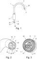
- the Fig. 1 shows a sanitary fitting 1 in a side view.
- the sanitary fitting 1 has a fitting housing 2, which includes a rotatably mounted outlet 3 with an outlet opening 4.
- the fitting housing 2 can be attached to a support, not shown here.
- a hose 5 runs through the sanitary fitting 1 and is in the Fig. 2 shown first lumen 6 at a first longitudinal end 25 of the tube 5 with a first liquid source 27, which is in the Fig. 2 shown second lumen 7 at the first longitudinal end 25 of the tube 5 with a second liquid source 28 and its in the Fig. 2 shown third lumen 8 are connected to a third liquid source 29 at the first longitudinal end 25 of the tube 5.
- the Fig. 2 shows a dem in the Fig. 1 shown first longitudinal end 25 opposite second longitudinal end 26 of the hose 5 in a perspective view.
- the first lumen 6 of the tube 5 is semicircular.
- the second lumen 7 and the third lumen 8 are quarter-circle shaped.
- the lumens 6, 7, 8 each include an inner wall 31 oriented in the direction of an outer surface 30 of the tube 5 with a lumen radius 32 around a center of the tube 5.
- the tube 5 has a casing 33 on its outer surface 30.
- the first lumen 6 is separated from the second lumen 7 and third lumen 8 by a first partition 34.
- the second lumen 7 and the third lumen 8 are separated from each other by a second partition 35.
- the Fig. 3 shows the adapter 9 in the Fig. 1 shown sanitary fitting 1 in a first perspective view with a view of a third longitudinal end 36 of the adapter 9.
- the adapter 9 comprises a first inlet 10 designed in the form of a first connecting nipple 15, a second inlet 11 designed in the form of a second connecting nipple 16 and an in Formed third inlet 12 in the form of a third connection nipple 17.
- a first outer contour of the first connection nipple 15 is congruent to a first inner contour of the Fig. 2 shown first lumen 6, a second outer contour of the second connection nipple 16 congruent to a second inner contour of the in the Fig.
- the Fig. 4 shows the adapter 9 in a second perspective view with a view of a fourth longitudinal end 37 of the adapter 9.
- the adapter 9 comprises an annular first outlet 13, into which the in the Fig. 3 shown first inlet 10 and second inlet 11 open, and a second outlet 14, into which the in the Fig. 3 shown third inlet 12 opens. This allows the first liquid to flow into the first outlet 13 via the first inlet 10, the second liquid to flow into the first outlet 13 via the second inlet 11 and the third liquid to flow into the second outlet 14 via the third inlet 12.
- the first outlet 13 and the second outlet 14 are concentric to one another and concentric to a longitudinal axis 38 of the adapter 9.
- the Fig. 5 shows the outlet 3 of the sanitary fitting 1 in one in the Fig. 1 Area marked with a circle 39 in a sectional view.
- the hose 5 is with its second longitudinal end 26 on the in the Fig. 3
- Connection nipples 15, 16, 17 shown are inserted and fastened to the adapter 9 with a union nut 21.
- a clamping ring 22, an annular spacer 23, an annular seal 40 and a crimping ring 24 are arranged between the adapter 9 and the union nut 21.
- the clamping ring 22, the annular spacer 23, the annular seal 40 and the squeeze ring 24 are arranged next to one another in the direction of the longitudinal axis 38 of the adapter 9 and the union nut 21, respectively.
- the union nut 21 is screwed onto the adapter 9, so that the hose 5 is clamped to the adapter 9 and cannot detach from the adapter 9.
- a mousseur 19 is plugged onto the fourth longitudinal end 37 of the adapter 9, so that the first outlet 13 of the adapter 9 is connected to a plurality of first liquid channels 18 of the mousseur 19 and the second outlet 14 of the adapter 9 is connected to a second liquid channel 20 of the mousseur 19 is.
- the first liquid and the second liquid can be delivered to an environment 41 via the first liquid channels 18 and the third liquid can be delivered to an environment 41 via the second liquid channel 20.
- the mousseur 19 forms the outlet opening 4 of the outlet 3.
- the Fig. 6 shows the outlet 3 with a view of the mousseur 19.
- the plurality of first liquid channels 18 are formed concentrically around the second liquid channel 20 and concentrically to the longitudinal axis 38.
- the second liquid channel 20 is concentric to the longitudinal axis 38.
- the liquids can be directed to the outlet opening 4 with less space required.
- the adapter 9 can reduce the complexity of the mousseur 19.
Landscapes
- Health & Medical Sciences (AREA)
- Life Sciences & Earth Sciences (AREA)
- Engineering & Computer Science (AREA)
- Hydrology & Water Resources (AREA)
- Public Health (AREA)
- Water Supply & Treatment (AREA)
- Infusion, Injection, And Reservoir Apparatuses (AREA)
Abstract
- ein Armaturengehäuse (2) mit einem Auslauf (3) und zumindest einer Auslauföffnung (4);
- einen Schlauch (5) mit zumindest einem ersten Lumen (6) zum Führen einer ersten Flüssigkeit, einem zweiten Lumen (7) zum Führen einer zweiten Flüssigkeit und einem dritten Lumen (8) zum Führen einer dritten Flüssigkeit; und
- einen Adapter (9) mit zumindest einem ersten Einlass (10) für das erste Lumen (6), einem zweiten Einlass (11) für das zweite Lumen (7) und einem dritten Einlass (12) für das dritte Lumen (8), wobei der erste Einlass (10) und der zweite Einlass (11) in einen ersten Auslass (13) des Adapters (9) münden und wobei der dritte Einlass (12) in einen zweiten Auslass (14) des Adapters (9) mündet.
Description
- Die vorliegende Erfindung betrifft eine Sanitärarmatur, die insbesondere im Zusammenhang mit Spülbecken und/oder Waschbecken verwendbar ist.
- Sanitärarmaturen dienen an Spülbecken, Waschbecken, Badewannen und/oder Duschen der bedarfsgerechten Bereitstellung einer Flüssigkeit, insbesondere Wasser. Hierzu können Sanitärarmaturen ein Gehäuse mit einem Auslauf und einer Auslauföffnung für die Flüssigkeit aufweisen. Das Gehäuse der Sanitärarmatur ist an einem Träger, beispielsweise einer Arbeitsplatte oder einem Spül- bzw. Waschbecken, befestigbar. Ferner können Sanitärarmaturen ein Mischventil oder eine Mischkartusche aufweisen, durch die Kaltwasser und Warmwasser zu Mischwasser mit einer gewünschten Mischwassertemperatur mischbar sind.
- Bekannt sind zudem Sanitärarmaturen, mit denen verschiedene Flüssigkeiten, zum Beispiel das Mischwasser, karbonisierte Flüssigkeit, aromatisierte Flüssigkeit, gefilterte Flüssigkeit, gekühlte Flüssigkeit und/oder Heißwasser zapfbar sind. Um die verschiedenen Flüssigkeiten von ihren jeweiligen Flüssigkeitsquellen zu der Auslauföffnung zu leiten sind mehrere Flüssigkeitsleitungen erforderlich, die sich parallel zueinander durch das Armaturengehäuse und/oder den Auslauf erstrecken. Hieraus folgt ein hoher Platzbedarf für die Flüssigkeitsleitungen, der eine Gestaltungsfreiheit der Armaturengehäuse bzw. Ausläufe einschränkt. Zudem können die einzelnen Flüssigkeiten über getrennte Auslauföffnungen der Sanitärarmaturen bzw. eines Mousseurs der Sanitärarmaturen abgebbar sein, damit diese vor ihrer Abgabe nicht in Kontakt miteinander kommen bzw. sich untereinander nicht mischen können. Bei einer hohen Anzahl von abgebbaren Flüssigkeiten muss daher eine entsprechend hohe Anzahl von Auslauföffnungen vorgesehen werden oder ein Mousseur eine entsprechend hohe Anzahl getrennter Flüssigkeitskanäle aufweisen, was eine Komplexität der Sanitärarmatur bzw. des Mousseurs erhöht.
- Aufgabe der Erfindung ist es daher, die mit Bezug auf den Stand der Technik geschilderten Probleme zumindest teilweise zu lösen und insbesondere eine Sanitärarmatur anzugeben, durch die verschiedene bzw. mehrere Flüssigkeiten mit geringerem Platzbedarf zu der Auslauföffnung leitbar sind und die eine geringere Komplexität aufweist.
- Diese Aufgaben werden gelöst mit einer Sanitärarmatur gemäß den Merkmalen des unabhängigen Patentanspruchs. Weitere vorteilhafte Ausgestaltungen der Sanitärarmatur sind in den abhängigen Patentansprüchen angegeben. Es ist darauf hinzuweisen, dass die in den abhängigen Patentansprüchen einzeln aufgeführten Merkmale in beliebiger technologisch sinnvoller Weise miteinander kombiniert werden können und weitere Ausgestaltungen der Erfindung definieren. Darüber hinaus werden die in den Patentansprüchen angegebenen Merkmale in der Beschreibung näher präzisiert und erläutert, wobei weitere bevorzugte Ausgestaltungen der Erfindung dargestellt werden.
- Hierzu trägt eine Sanitärarmatur bei, die zumindest die folgenden Komponenten aufweist:
- ein Armaturengehäuse mit einem Auslauf und zumindest einer Auslauföffnung;
- einen Schlauch mit zumindest einem ersten Lumen zum Führen einer ersten Flüssigkeit, einem zweiten Lumen zum Führen einer zweiten Flüssigkeit und einem dritten Lumen zum Führen einer dritten Flüssigkeit; und
- einen Adapter mit zumindest einem ersten Einlass für das erste Lumen, einem zweiten Einlass für das zweite Lumen und einem dritten Einlass für das dritte Lumen, wobei der erste Einlass und der zweite Einlass in einen ersten Auslass des Adapters münden und wobei der dritte Einlass in einen zweiten Auslass des Adapters mündet.
- Die Sanitärarmatur dient insbesondere der bedarfsgerechten Bereitstellung von Flüssigkeiten, wie insbesondere Wasser, an Spülbecken und/oder Waschbecken. Die Sanitärarmatur umfasst ein Armaturengehäuse, das insbesondere zumindest teilweise aus Kunststoff und/oder (Guss-)Metall, wie zum Beispiel Messing, bestehen kann. Das Armaturengehäuse ist an einem Träger, beispielsweise einer Arbeitsplatte, dem Spülbecken oder Waschbecken, befestigbar und/oder weist einen (hervorstehenden bzw. abzweigenden) Auslauf auf, der starr oder bewegbar mit dem Armaturengehäuse verbunden ist. Der Auslauf kann zumindest teilweise rohrförmig ausgebildet sein und/oder weist zumindest eine Auslauföffnung auf. Die zumindest eine Auslauföffnung kann beispielsweise nach Art eines Strahlbildners oder Mousseurs ausgebildet sein.
- Die Sanitärarmatur weist einen Schlauch auf. Der Schlauch kann zumindest teilweise durch das Armaturengehäuse und/oder den Auslauf verlaufen. Der Schlauch weist insbesondere einen runden Querschnitt auf. Der Schlauch besteht insbesondere zumindest teilweise aus einem für Trinkwasser zugelassenen und/oder geeigneten Material. Das Material des Schlauchs kann mindestens eine, mehrere oder sogar jede der folgenden Eigenschaften aufweisen:
- temperaturbeständig bei -40 °C bis 200 °C [Celsius] sein;
- transluzent sein;
- elastisch sein;
- eine Härte von 70 bis 85 Shore A aufweisen;
- eine Dichte von 1,22 g/cm3 [Gramm pro Kubikzentimeter] bis 1,26 g/cm3, bevorzugt (circa) 1,24 g/cm3, aufweisen;
- eine Reißfestigkeit von 8,6 N/mm2 [Newton pro Quadratmillimeter] bis 8,8 N/mm2, bevorzugt (circa) 8,7 N/mm2, aufweisen;
- eine Reißdehnung von 390 % bis 410 %, bevorzugt (circa) 400 %, aufweisen; und/oder
- eine Weiterreißfestigkeit von 30 N/mm [Newton pro Quadratmillimeter] bis 34 N/mm, bevorzugt (circa) 32 N/mm, aufweisen.
- Der Schlauch weist zumindest ein erstes Lumen zum Führen einer ersten Flüssigkeit von einer ersten Flüssigkeitsquelle zu der Auslauföffnung, ein zweites Lumen zum Führen einer zweiten Flüssigkeit von einer zweiten Flüssigkeitsquelle zu der Auslauföffnung und ein drittes Lumen zum Führen einer dritten Flüssigkeit von einer dritten Flüssigkeitsquelle zu der Auslauföffnung auf. Darüber hinaus kann der Schlauch zumindest ein weiteres Lumen zum Führen zumindest einer weiteren Flüssigkeit von zumindest einer weiteren Flüssigkeitsquelle aufweisen. Bei den Lumen handelt es sich insbesondere jeweils um einen (röhrenförmigen) Flüssigkeitskanal, der sich von einem ersten längsseitigen Ende des Schlauchs bis zu einem zweiten längsseitigen Ende des Schlauchs durch den Schlauch erstreckt. Das erste längsseitige Ende des Schlauchs kann mit der einen ersten Flüssigkeitsquelle, zweiten Flüssigkeitsquelle und dritten Flüssigkeitsquelle (und ggf. der zumindest einen weiteren Flüssigkeitsquelle) verbunden sein. Alternativ kann das erste längsseitige Ende des Schlauchs mit einer Verteilervorrichtung für die zumindest eine erste Flüssigkeitsquelle, zweite Flüssigkeitsquelle und dritte Flüssigkeitsquelle (und ggf. für die zumindest eine weitere Flüssigkeitsquelle) verbunden sein. Die Verteilervorrichtung kann mit der ersten Flüssigkeitsquelle, zweiten Flüssigkeitsquelle und dritten Flüssigkeitsquelle (und ggf. der zumindest einen weiteren Flüssigkeitsquelle) verbunden sein. Die Verteilervorrichtung kann außerhalb des Armaturengehäuses und/oder des Auslaufs angeordnet sein. Die einzelnen Lumen verlaufen insbesondere parallel zueinander durch den Schlauch. Die Lumen sind durch das Material des Schlauchs insbesondere (gemeinsam) einstückig ausgebildet. Die Lumen verlaufen insbesondere nicht konzentrisch zueinander. Der Schlauch kann nach Art eines Mehrlumenschlauchs bzw. Multilumenschlauchs und/oder nicht rotationssymmetrisch ausgebildet sein.
- Bei der ersten Flüssigkeit kann es sich beispielsweise um Mischwasser und/oder bei der ersten Flüssigkeitsquelle beispielsweise um ein Mischventil oder eine Mischkartusche handeln. Durch das Mischventil bzw. die Mischkartusche sind insbesondere Kaltwasser mit einer Kaltwassertemperatur und Warmwasser mit einer Warmwassertemperatur zu dem Mischwasser mit einer gewünschten Mischwassertemperatur mischbar. Die Kaltwassertemperatur beträgt insbesondere maximal 25 °C, bevorzugt 1 °C bis 25 °C, besonders bevorzugt 5 °C bis 20 °C und/oder die Warmwassertemperatur insbesondere maximal 90 °C, bevorzugt 25 °C bis 90 °C, besonders bevorzugt 55 °C bis 65 °C. Das Mischventil oder die Mischkartusche können in dem Armaturengehäuse der Sanitärarmatur angeordnet sein. Bei der zweiten Flüssigkeit, der dritten Flüssigkeit und/oder der zumindest einen weiteren Flüssigkeit kann es sich zum Beispiel um Trinkwasser, Mischwasser, Kaltwasser, Warmwasser, karbonisierte Flüssigkeit, aromatisierte Flüssigkeit, gefilterte Flüssigkeit, gekühlte Flüssigkeit (beispielsweise mit einer Kühlwassertemperatur von 1 °C bis 10 °C) und/oder Heißwasser (beispielsweise mit einer Heißwassertemperatur von 90 °C bis 100 °C) handeln. Beispielsweise kann es sich bei der zweiten Flüssigkeit um Heißwasser und der dritten Flüssigkeit um gefilterte Flüssigkeit bzw. gefiltertes Wasser handeln.
- Durch den Schlauch sind zumindest drei Flüssigkeiten getrennt voneinander durch einen einzigen Schlauch der zumindest einen Auslauföffnung zuführbar, wodurch sich der Platzbedarf in dem Armaturengehäuse bzw. dem Auslauf reduziert. Der Schlauch kann einen Außendurchmesser von beispielsweise 12 mm bis 18 mm, bevorzugt 14 mm bis 15 mm, aufweisen. Ein erster Querschnitt des ersten Lumens kann halbkreisförmig ausgebildet sein. Der erste Querschnitt ist insbesondere orthogonal zu einer Längsachse des Schlauchs ausgerichtet. Ein zweiter Querschnitt des zweiten Lumens und/oder ein dritter Querschnitt des dritten Lumens können teilkreisförmig ausgebildet sein. Das zumindest eine weitere Lumen kann teilkreisförmig ausgebildet sein. Insbesondere können der zweite Querschnitt des zweiten Lumens und/oder der dritte Querschnitt des dritten Lumens viertelkreisförmig ausgebildet sein. Der zweite Querschnitt und/oder der dritte Querschnitt sind insbesondere orthogonal zu der Längsachse des Schlauchs ausgerichtet.
- Das erste Lumen ist von dem zweiten Lumen, dem dritten Lumen und/oder dem zumindest einen weiteren Lumen insbesondere durch eine erste Trennwand getrennt. Das zweite Lumen, dritte Lumen und/oder das zumindest eine weitere Lumen sind insbesondere durch zumindest eine zweite Trennwand voneinander getrennt. Die erste Trennwand weist insbesondere eine erste Dicke von beispielsweise 1 mm bis 1,5 mm und/oder die zweite Trennwand insbesondere eine zweite Dicke von beispielsweise 1 mm bis 1,5 mm auf.
- Das erste Lumen, zweite Lumen, dritte Lumen und/oder das zumindest eine weitere Lumen können jeweils eine in Richtung der Außenfläche des Schlauchs orientierte Innenwand mit einem Lumenradius aufweisen. Der Lumenradius kann beispielsweise 4 mm bis 8 mm, bevorzugt 5 mm bis 6 mm, besonders bevorzugt (circa) 5,5 mm, betragen.
- Erste Ecken eines ersten Querschnitts des ersten Lumens, zweite Ecken eines zweiten Querschnitts des zweiten Lumens und/oder dritte Ecken eines dritten Querschnitts des dritten Lumens können einen Radius von 0,4 mm bis 0,6 mm aufweisen. Vorzugsweise kann der Radius (circa) 0,5 mm betragen. Hierdurch lässt sich ein Strömungswiderstand der Flüssigkeit in den Lumen reduzieren, ohne dass eine Lumenquerschnittsfläche der einzelnen Lumen zu stark reduziert wird.
- Die Sanitärarmatur weist einen Adapter mit zumindest einem ersten Einlass für das erste Lumen, einem zweiten Einlass für das zweite Lumen und einem dritten Einlass für das dritte Lumen auf. Der Adapter kann eine, mehrere oder sogar alle der nachfolgenden Eigenschaften aufweisen:
- zumindest teilweise aus Kunststoff und/oder Metall, wie zum Beispiel Messing, bestehen;
- nach Art eines Kunststoffspritzgussteils ausgebildet sein;
- einstückig ausgebildet sein;
- zumindest einen weiteren Einlass für das zumindest eine weitere Lumen aufweisen;
- eine Anzahl Einlässe aufweisen, die einer Anzahl Lumen des Schlauchs entspricht;
- sich entlang einer Längsachse erstrecken;
- (insbesondere parallel zu der Längsachse) eine Länge von 10 mm bis 60 mm aufweisen;
- (insbesondere orthogonal zu der Längsachse) einen Durchmesser von 5 mm bis 50 mm aufweisen;
- eine runde Umfangsfläche aufweisen;
- ein erstes Außengewinde oder erstes Innengewinde aufweisen.
- Der zumindest eine erste Einlass, zweite Einlass, dritte Einlass und/oder weitere Einlass können an einem ersten längsseitigen Ende des Adapters ausgebildet sein. Der erste Einlass, zweiter Einlass, dritte Einlass und/oder weitere Einlass können nach Art einer Öffnung und/oder nach Art eines Kanals in dem Adapter ausgebildet sein. Der Schlauch ist insbesondere derart mit dem Adapter verbunden, dass das erste Lumen mit dem ersten Einlass, das zweite Lumen mit dem zweiten Einlass und das dritte Lumen mit dem dritten Einlass verbunden sind. Weiterhin kann der Schlauch insbesondere derart mit dem Adapter verbunden sein, dass das zumindest eine weitere Lumen mit dem zumindest einen weiteren Einlass verbunden ist. Hierdurch kann die erste Flüssigkeit von dem ersten Lumen (insbesondere direkt) in den ersten Einlass, die zweite Flüssigkeit von dem zweiten Lumen (insbesondere direkt) in den zweiten Einlass, die dritte Flüssigkeit von dem dritten Lumen (insbesondere direkt) in den dritten Einlass und/oder die zumindest eine weitere Flüssigkeit von dem zumindest einen weiteren Lumen (insbesondere direkt) in den zumindest einen weiteren Einlass strömen. Die Verbindung zwischen dem Schlauch und dem Adapter kann beispielsweise nach Art einer Steckverbindung, Klemmverbindung, Klebeverbindung, Schraubverbindung und/oder Bajonettverbindung ausgeführt sein.
- Der erste Einlass und der zweite Einlass münden in einen ersten Auslass. Somit münden der erste Einlass und der zweite Einlass in einen gemeinsamen ersten Auslass. Die erste Flüssigkeit und die zweite Flüssigkeit können hierdurch in den ersten Auslass strömen und/oder den Adapter über den ersten Auslass verlassen. Der dritte Einlass mündet in einen zweiten Auslass des Adapters. Die dritte Flüssigkeit kann hierdurch in den zweiten Auslass strömen und/oder den Adapter über den zweiten Auslass verlassen. Über den ersten Auslass des Adapters sind die erste Flüssigkeit und die zweite Flüssigkeit insbesondere einer (gemeinsamen) ersten Auslauföffnung der Sanitärarmatur oder zumindest einem (gemeinsamen) ersten Flüssigkeitskanal eines Mousseurs der Sanitärarmatur zuführbar. Über den zweiten Auslass des Adapters ist die dritte Flüssigkeit insbesondere einer zweiten Auslauföffnung der Sanitärarmatur oder zumindest einem zweiten Flüssigkeitskanal des Mousseurs der Sanitärarmatur zuführbar. Der Adapter kann zumindest einen Einlass mehr als Auslässe aufweisen. Zumindest ein Teil der Einlässe kann in zumindest einen gemeinsamen Auslass münden. Durch den Adapter ist dadurch eine Anzahl von Auslauföffnungen der Sanitärarmatur und/oder eine Anzahl von (insbesondere getrennten) Flüssigkeitskanälen in dem Mousseur reduzierbar.
- Der erste Einlass kann in Form eines ersten Anschlussnippels, der zweite Einlass in Form eines zweiten Anschlussnippels und der dritte Einlass in Form eines dritten Anschlussnippels ausgebildet sein, wobei der Schlauch mit dem ersten Lumen auf den ersten Anschlussnippel, mit dem zweiten Lumen auf den zweiten Anschlussnippel und dem dritten Lumen auf den dritten Anschlussnippel gesteckt ist. Der zumindest eine weitere Einlass kann in Form zumindest eines weiteren Anschlussnippels ausgebildet sein, wobei der Schlauch mit dem zumindest einen weiteren Lumen auf den zumindest einen weiteren Anschlussnippel gesteckt sein kann. Die Anschlussnippel können insbesondere rohrförmig ausgebildet sein und/oder sich in Richtung der Längsachse des Adapters erstrecken. Die Anschlussnippel können (insbesondere parallel zu der Längsachse) beispielsweise eine Anschlussnippellänge von 1 mm bis 15 mm aufweisen. Außenkonturen der Anschlussnippel können kongruent zu Innenkonturen der Lumen ausgebildet sein.
- Der erste Auslass des Adapters und der zweite Auslass des Adapters können koaxial zueinander ausgebildet sein.
- Der erste Auslass des Adapters kann sich um den zweiten Auslass des Adapters erstrecken. Der erste Auslass kann zumindest teilweise nach Art eines ringförmigen Kanals ausgebildet sein, zumindest teilweise einen geraden Verlauf aufweisen und/oder sich zumindest teilweise parallel zu der Längsachse erstrecken. Der zweite Auslass kann zumindest teilweise einen geraden Verlauf aufweisen und/oder sich zumindest teilweise parallel zu der Längsachse erstrecken.
- Der erste Auslass des Adapters kann in zumindest einen ersten Flüssigkeitskanal eines Mousseurs und der zweite Auslass des Adapters in zumindest einen zweiten Flüssigkeitskanal des Mousseurs münden. Zumindest ein weiterer Auslass des Adapters kann in zumindest einen weiteren Flüssigkeitskanal des Mousseurs münden. Der zumindest eine erste Flüssigkeitskanal, der zumindest eine zweite Flüssigkeitskanal und/oder der zumindest eine weitere Flüssigkeitskanal können zumindest teilweise einen geraden Verlauf aufweisen und/oder sich zumindest teilweise parallel zu der Längsachse des Adapters erstrecken. Der zumindest eine erste Flüssigkeitskanal, der zumindest eine zweite Flüssigkeitskanal und/oder der zumindest eine weitere Flüssigkeitskanal können in eine Umgebung der Sanitärarmatur münden. Hierdurch sind die Flüssigkeiten über die Flüssigkeitskanäle an die Umgebung abgebbar. Der Mousseur kann nach Art eines Luftsprudlers ausgebildet sein. Der Adapter ist insbesondere derart mit dem Mousseur verbunden, dass der erste Auslass des Adapters mit dem zumindest einen ersten Flüssigkeitskanal des Mousseurs, der zweite Auslass des Adapters mit dem zumindest einen zweiten Flüssigkeitskanal des Mousseurs und/oder der zumindest eine weitere Auslass des Adapters mit dem zumindest einen weiteren Flüssigkeitskanal des Mousseurs verbunden ist. Hierdurch können die erste Flüssigkeit und zweite Flüssigkeit von dem ersten Auslass des Adapters (insbesondere direkt) in den zumindest einen ersten Flüssigkeitskanal des Mousseurs und/oder die dritte Flüssigkeit von dem zweiten Auslass des Adapters (insbesondere direkt) in den zumindest einen zweiten Flüssigkeitskanal des Mousseurs strömen. Die Verbindung zwischen dem Adapter und dem Mousseur kann beispielsweise nach Art einer Steckverbindung, Klemmverbindung, Klebeverbindung, Schraubverbindung und/oder Bajonettverbindung ausgeführt sein.
- Der zumindest eine erste Flüssigkeitskanal des Mousseurs kann sich um den zumindest einen zweiten Flüssigkeitskanal des Mousseurs erstrecken. Der Mousseurs kann einen einzigen ersten Flüssigkeitskanal und/oder eine Vielzahl von zweiten Flüssigkeitskanälen aufweisen, wobei die Vielzahl von zweiten Flüssigkeitskanälen insbesondere ringförmig um den ersten Flüssigkeitskanal angeordnet sein können.
- Der Adapter kann mithilfe einer Überwurfmutter an dem Schlauch befestigt sein. Hierzu kann die Überwurfmutter auf den Schlauch gesteckt und/oder mit dem Adapter verschraubt sein. Die Überwurfmutter kann hierfür ein zweites Innengewinde oder ein zweites Außengewinde aufweisen. Die Überwurfmutter kann zumindest teilweise hülsenförmig ausgebildet sein.
- Zwischen dem Adapter und der Überwurfmutter kann ein Klemmring angeordnet sein. Der Klemmring kann ringförmig ausgebildet, auf den Schlauch gesteckt und/oder durch die Überwurfmutter gegen den Schlauch gepresst sein.
- Zwischen dem Adapter und der Überwurfmutter kann ein Abstandshalter angeordnet sein. Der Abstandshalter kann ringförmig ausgebildet, auf den Schlauch gesteckt und/oder (parallel zu der Längsachse) neben dem Klemmring angeordnet sein.
- Zwischen dem Adapter und der Überwurfmutter kann ein Quetschring angeordnet sein. Der Quetschring kann ringförmig ausgebildet, auf den Schlauch gesteckt und/oder (parallel zu der Längsachse) neben dem Adapter angeordnet sein.
- Zwischen dem Abstandshalter und dem Quetschring kann eine ringförmige Dichtung angeordnet sein.
- Die Erfindung sowie das technische Umfeld werden nachfolgend anhand der Figuren näher erläutert. Es ist darauf hinzuweisen, dass die Figuren eine besonders bevorzugte Ausführungsvariante der Erfindung zeigen, diese jedoch nicht darauf beschränkt ist. Dabei sind gleiche Bauteile in den Figuren mit denselben Bezugszeichen versehen. Es zeigen beispielhaft und schematisch:
- Fig. 1:
- eine Sanitärarmatur in einer Seitenansicht;
- Fig. 2:
- ein Schlauch der Sanitärarmatur in einem Querschnitt;
- Fig. 3:
- ein Adapter der Sanitärarmatur in einer ersten perspektivischen Darstellung;
- Fig. 4:
- der Adapter der Sanitärarmatur in einer zweiten perspektivischen Darstellung;
- Fig. 5:
- ein Auslauf der Sanitärarmatur in einer Schnittdarstellung; und
- Fig. 6:
- der Auslauf der Sanitärarmatur mit Blick auf einen Mousseur.
- Die
Fig. 1 zeigt eine Sanitärarmatur 1 in einer Seitenansicht. Die Sanitärarmatur 1 weist ein Armaturengehäuse 2 auf, das einen drehbar gelagerten Auslauf 3 mit einer Auslauföffnung 4 umfasst. Das Armaturengehäuse 2 ist an einem hier nicht gezeigten Träger befestigbar. Durch die Sanitärarmatur 1 verläuft ein Schlauch 5, dessen in derFig. 2 gezeigtes erstes Lumen 6 an einem ersten längsseitigen Ende 25 des Schlauchs 5 mit einer ersten Flüssigkeitsquelle 27, dessen in derFig. 2 gezeigtes zweites Lumen 7 an dem ersten längsseitigen Ende 25 des Schlauchs 5 mit einer zweiten Flüssigkeitsquelle 28 und dessen in derFig. 2 gezeigtes drittes Lumen 8 an dem ersten längsseitigen Ende 25 des Schlauchs 5 mit einer dritten Flüssigkeitsquelle 29 verbunden sind. - Die
Fig. 2 zeigt ein dem in derFig. 1 gezeigten ersten längsseitigen Ende 25 gegenüberliegendes zweites längsseitiges Ende 26 des Schlauchs 5 in einer perspektivischen Darstellung. Das erste Lumen 6 des Schlauchs 5 ist halbkreisförmig ausgebildet. Das zweite Lumen 7 und das dritte Lumen 8 sind viertelkreisförmig ausgebildet. Die Lumen 6, 7, 8 umfassen jeweils eine in Richtung einer Außenfläche 30 des Schlauchs 5 orientierte Innenwand 31 mit einem Lumenradius 32 um ein Zentrum des Schlauchs 5. Der Schlauch 5 weist an seiner Außenfläche 30 eine Ummantelung 33 auf. Das erste Lumen 6 ist von dem zweiten Lumen 7 und drittem Lumen 8 durch eine erste Trennwand 34 getrennt. Das zweite Lumen 7 und das dritte Lumen 8 sind durch eine zweite Trennwand 35 voneinander getrennt. - Die
Fig. 3 zeigt den Adapter 9 der in derFig. 1 gezeigten Sanitärarmatur 1 in einer ersten perspektivischen Darstellung mit Blick auf ein drittes längsseitiges Ende 36 des Adapters 9. Der Adapter 9 umfasst einen in Form eines ersten Anschlussnippels 15 ausgebildeten ersten Einlass 10, einen in Form eines zweiten Anschlussnippels 16 ausgebildeten zweiten Einlass 11 und einen in Form eines dritten Anschlussnippels 17 ausgebildeten dritten Einlass 12 auf. Eine erste Außenkontur des ersten Anschlussnippels 15 ist kongruent zu einer ersten Innenkontur des in derFig. 2 gezeigten ersten Lumens 6, eine zweite Außenkontur des zweiten Anschlussnippels 16 kongruent zu einer zweiten Innenkontur des in derFig. 2 gezeigten zweiten Lumens 7 und eine dritte Außenkontur des dritten Anschlussnippels 17 kongruent zu einer dritten Innenkontur des in derFig. 2 gezeigten dritten Lumens 8 ausgebildet. Hierdurch ist der in derFig. 2 gezeigte Schlauch 5 mit dem ersten Lumen 6 auf den ersten Anschlussnippel 15, mit dem zweiten Lumen 7 auf den zweiten Anschlussnippel 16 und mit dem dritten Lumen 8 auf den dritten Anschlussnippel 17 steckbar. Hierdurch kann eine erste Flüssigkeit aus dem ersten Lumen 6 in den ersten Einlass 10, eine zweite Flüssigkeit aus dem zweiten Lumen 7 in den zweiten Einlass 11 und eine dritte Flüssigkeit aus dem dritten Lumen 8 in den dritten Einlass 12 strömen. - Die
Fig. 4 zeigt den Adapter 9 in einer zweiten perspektivischen Darstellung mit Blick auf ein viertes längsseitiges Ende 37 des Adapters 9. Der Adapter 9 umfasst einen ringförmigen ersten Auslass 13, in den der in derFig. 3 gezeigte erste Einlass 10 und zweite Einlass 11 münden, und einen zweiten Auslass 14, in den der in derFig. 3 gezeigte dritte Einlass 12 mündet. Hierdurch können die erste Flüssigkeit über den ersten Einlass 10 in den ersten Auslass 13, die zweite Flüssigkeit über den zweiten Einlass 11 in den ersten Auslass 13 und die dritte Flüssigkeit über den dritten Einlass 12 in den zweiten Auslass 14 strömen. Der erste Auslass 13 und der zweite Auslass 14 sind konzentrisch zueinander und konzentrisch zu einer Längsachse 38 des Adapters 9 ausgebildet. - Die
Fig. 5 zeigt den Auslauf 3 der Sanitärarmatur 1 in einem in derFig. 1 mit einem Kreis 39 gekennzeichneten Bereich in einer Schnittdarstellung. Der Schlauch 5 ist mit seinem zweiten längsseitigen Ende 26 auf die in derFig. 3 gezeigten Anschlussnippel 15, 16, 17 gesteckt und mit einer Überwurfmutter 21 an dem Adapter 9 befestigt. Zwischen dem Adapter 9 und der Überwurfmutter 21 sind ein Klemmring 22, ein ringförmiger Abstandshalter 23, eine ringförmige Dichtung 40 und ein Quetschring 24 angeordnet. Der Klemmring 22, der ringförmige Abstandshalter 23, die ringförmige Dichtung 40 und der Quetschring 24 sind in Richtung der Längsachse 38 des Adapters 9 bzw. der Überwurfmutter 21 nebeneinander angeordnet. Die Überwurfmutter 21 ist auf den Adapter 9 geschraubt, sodass der Schlauch 5 mit dem Adapter 9 verspannt ist und sich nicht von dem Adapter 9 lösen kann. - Auf das vierte längsseitige Ende 37 des Adapters 9 ist ein Mousseur 19 gesteckt, sodass der erste Auslass 13 des Adapters 9 mit einer Vielzahl von ersten Flüssigkeitskanälen 18 des Mousseurs 19 und der zweite Auslass 14 des Adapters 9 mit einem zweiten Flüssigkeitskanal 20 des Mousseurs 19 verbunden ist. Hierdurch sind die erste Flüssigkeit und die zweite Flüssigkeit über die ersten Flüssigkeitskanäle 18 und die dritte Flüssigkeit über den zweiten Flüssigkeitskanal 20 an eine Umgebung 41 abgebbar. Der Mousseur 19 bildet die Auslauföffnung 4 des Auslaufs 3.
- Die
Fig. 6 zeigt den Auslauf 3 mit Blick auf den Mousseur 19. Die Vielzahl von ersten Flüssigkeitskanäle 18 sind konzentrisch um den zweiten Flüssigkeitskanal 20 und konzentrisch zu der Längsachse 38 ausgebildet. Der zweite Flüssigkeitskanal 20 ist konzentrisch zu der Längsachse 38 ausgebildet. - Durch die vorliegende Erfindung sind die Flüssigkeiten mit geringerem Platzbedarf zu der Auslauföffnung 4 leitbar. Zudem ist durch den Adapter 9 eine Komplexität des Mousseurs 19 reduzierbar.
-
- 1
- Sanitärarmatur
- 2
- Armaturengehäuse
- 3
- Auslauf
- 4
- Auslauföffnung
- 5
- Schlauch
- 6
- erstes Lumen
- 7
- zweites Lumen
- 8
- drittes Lumen
- 9
- Adapter
- 10
- erster Einlass
- 11
- zweiter Einlass
- 12
- dritter Einlass
- 13
- erster Auslass
- 14
- zweiter Auslass
- 15
- erster Anschlussnippel
- 16
- zweiter Anschlussnippel
- 17
- dritter Anschlussnippel
- 18
- erster Flüssigkeitskanal
- 19
- Mousseur
- 20
- zweiter Flüssigkeitskanal
- 21
- Überwurfmutter
- 22
- Klemmring
- 23
- Abstandshalter
- 24
- Quetschring
- 25
- erstes längsseitiges Ende
- 26
- zweites längsseitiges Ende
- 27
- erste Flüssigkeitsquelle
- 28
- zweite Flüssigkeitsquelle
- 29
- dritte Flüssigkeitsquelle
- 30
- Außenfläche
- 31
- Innenwand
- 32
- Lumenradius
- 33
- Ummantelung
- 34
- erste Trennwand
- 35
- zweite Trennwand
- 36
- drittes längsseitiges Ende
- 37
- viertes längsseitiges Ende
- 38
- Längsachse
- 39
- Kreis
- 40
- Dichtung
- 41
- Umgebung
Claims (10)
- Sanitärarmatur (1), zumindest aufweisend:- ein Armaturengehäuse (2) mit einem Auslauf (3) und zumindest einer Auslauföffnung (4);- einen Schlauch (5) mit zumindest einem ersten Lumen (6) zum Führen einer ersten Flüssigkeit, einem zweiten Lumen (7) zum Führen einer zweiten Flüssigkeit und einem dritten Lumen (8) zum Führen einer dritten Flüssigkeit; und- einen Adapter (9) mit zumindest einem ersten Einlass (10) für das erste Lumen (6), einem zweiten Einlass (11) für das zweite Lumen (7) und einem dritten Einlass (12) für das dritte Lumen (8), wobei der erste Einlass (10) und der zweite Einlass (11) in einen ersten Auslass (13) des Adapters (9) münden und wobei der dritte Einlass (12) in einen zweiten Auslass (14) des Adapters (9) mündet.
- Sanitärarmatur (1) nach Patentanspruch 1, wobei der erste Einlass (10) in Form eines ersten Anschlussnippels (15), der zweite Einlass (12) in Form eines zweiten Anschlussnippels (16) und der dritte Einlass (12) in Form eines dritten Anschlussnippels (17) ausgebildet sind und wobei der Schlauch (5) mit dem ersten Lumen (6) auf den ersten Anschlussnippel (15), mit dem zweiten Lumen (7) auf den zweiten Anschlussnippel (16) und dem dritten Lumen (8) auf den dritten Anschlussnippel (17) gesteckt ist.
- Sanitärarmatur (1) nach einem der vorhergehenden Patentansprüche, wobei der erste Auslass (13) des Adapters (9) und der zweite Auslass (14) des Adapters (9) koaxial zueinander ausgebildet sind.
- Sanitärarmatur (1) nach einem der vorhergehenden Patentansprüche, wobei sich der erste Auslass (13) des Adapters (9) um den zweiten Auslass (14) des Adapters (9) erstreckt.
- Sanitärarmatur (1) nach einem der vorhergehenden Patentansprüche, wobei der erste Auslass (13) des Adapters (9) in zumindest einen ersten Flüssigkeitskanal (18) eines Mousseurs (19) und der zweite Auslass (14) des Adapters (9) in zumindest einen zweiten Flüssigkeitskanal (20) des Mousseurs (19) mündet.
- Sanitärarmatur (1) nach Patentanspruch 5, wobei der zumindest eine erste Flüssigkeitskanal (18) des Mousseurs (19) sich um den zumindest einen zweiten Flüssigkeitskanal (20) des Mousseurs (19) erstreckt.
- Sanitärarmatur (1) nach einem der vorhergehenden Patentansprüche, wobei der Adapter (9) mithilfe einer Überwurfmutter (21) an dem Schlauch (5) befestigt ist.
- Sanitärarmatur (1) nach Patentanspruch 7, wobei zwischen dem Adapter (9) und der Überwurfmutter (21) ein Klemmring (22) angeordnet ist.
- Sanitärarmatur (1) nach Patentanspruch 7 oder 8, wobei zwischen dem Adapter (9) und der Überwurfmutter (21) ein Abstandshalter (23) angeordnet ist.
- Sanitärarmatur (1) nach einem der vorhergehenden Patentansprüche, wobei zwischen dem Adapter (9) und der Überwurfmutter (21) ein Quetschring (24) angeordnet ist.
Applications Claiming Priority (1)
| Application Number | Priority Date | Filing Date | Title |
|---|---|---|---|
| DE102022106832.3A DE102022106832A1 (de) | 2022-03-23 | 2022-03-23 | Sanitärarmatur mit einem Schlauch |
Publications (2)
| Publication Number | Publication Date |
|---|---|
| EP4249691A1 true EP4249691A1 (de) | 2023-09-27 |
| EP4249691B1 EP4249691B1 (de) | 2025-02-26 |
Family
ID=85704817
Family Applications (1)
| Application Number | Title | Priority Date | Filing Date |
|---|---|---|---|
| EP23162700.1A Active EP4249691B1 (de) | 2022-03-23 | 2023-03-17 | Sanitärarmatur mit einem schlauch |
Country Status (2)
| Country | Link |
|---|---|
| EP (1) | EP4249691B1 (de) |
| DE (1) | DE102022106832A1 (de) |
Citations (2)
| Publication number | Priority date | Publication date | Assignee | Title |
|---|---|---|---|---|
| US20220049479A1 (en) * | 2018-09-13 | 2022-02-17 | Grohe Ag | Outlet for a water armature |
| WO2022189444A1 (de) * | 2021-03-12 | 2022-09-15 | Grohe Ag | Wasserarmaturanordnung für verschiedene strahlbilder |
Family Cites Families (2)
| Publication number | Priority date | Publication date | Assignee | Title |
|---|---|---|---|---|
| DE102014001818B4 (de) | 2014-02-13 | 2025-05-28 | Grohe Ag | Anschlussstück für einen Auslauf einer Sanitärarmatur |
| DE102017101566B3 (de) | 2017-01-26 | 2018-06-28 | Neoperl Gmbh | Schlauchanschlussanordnung, Verwendung einer Schlauchanschlussanordnung und Sanitärarmatur |
-
2022
- 2022-03-23 DE DE102022106832.3A patent/DE102022106832A1/de active Pending
-
2023
- 2023-03-17 EP EP23162700.1A patent/EP4249691B1/de active Active
Patent Citations (2)
| Publication number | Priority date | Publication date | Assignee | Title |
|---|---|---|---|---|
| US20220049479A1 (en) * | 2018-09-13 | 2022-02-17 | Grohe Ag | Outlet for a water armature |
| WO2022189444A1 (de) * | 2021-03-12 | 2022-09-15 | Grohe Ag | Wasserarmaturanordnung für verschiedene strahlbilder |
Also Published As
| Publication number | Publication date |
|---|---|
| DE102022106832A1 (de) | 2023-09-28 |
| EP4249691B1 (de) | 2025-02-26 |
Similar Documents
| Publication | Publication Date | Title |
|---|---|---|
| EP4111007B1 (de) | Strahlregler für eine sanitärarmatur mit mindestens drei flüssigkeitskanälen | |
| DE69531790T2 (de) | Duschaufsatz | |
| DE102013203946A1 (de) | Sanitärleitung, insbesondere für eine Duschbrause | |
| EP4190984A1 (de) | Strahlregler für eine sanitärarmatur sowie sanitärarmatur mit einem solchen strahlregler | |
| EP0119960B1 (de) | Sanitär-Armaturanschlussorgan | |
| DE102014001818B4 (de) | Anschlussstück für einen Auslauf einer Sanitärarmatur | |
| DE102016000766B4 (de) | Sanitäres Auslaufstück, Sanitärarmatur und Verwendung eines Auslaufstücks | |
| EP4249691B1 (de) | Sanitärarmatur mit einem schlauch | |
| CH653426A5 (de) | Verbindungsvorrichtung fuer sanitaerinstallationen mit flexibler, beiderends anschlussmittel aufweisender verbindungsleitung. | |
| DE3348053C2 (en) | Water-dispensing device | |
| DE4421387B4 (de) | Einlochmischbatterie | |
| EP4245930A1 (de) | Sanitärarmatur mit einem schlauch | |
| EP3546421B1 (de) | Zapfvorrichtung aufweisend einen düseneinsatz mit einer prallwand | |
| DE102021101779A1 (de) | Strahlregler für eine Sanitärarmatur sowie Sanitärarmatur mit einem entsprechenden Strahlregler | |
| EP3330443B1 (de) | Sanitärarmatur mit zumindest einem ein rückschlagventil aufweisenden anschlussstück | |
| EP1219342B1 (de) | Vorrichtung zur Aufbereitung einer Flüssigkeit | |
| EP3310971B1 (de) | Sanitärarmatur für mehrere fluide | |
| EP4249690A1 (de) | Sanitärarmatur | |
| DE102015002590A1 (de) | Sanitärarmatur mit Dichtelement für herausziehbare Brause | |
| WO2024200559A1 (de) | Sanitärarmatur und verfahren zur montage einer sanitärarmatur | |
| DE3826009C2 (de) | Anschlußvorrichtung für eine sanitäre Mischarmatur | |
| DE102022106357A1 (de) | Armatur einer Sanitäreinrichtung und Sanitäreinrichtung | |
| EP3369868A1 (de) | Sanitäre aufputz-mischbatterie | |
| EP4603645A1 (de) | Sanitäres auslaufstück | |
| DE102023111894A1 (de) | Steckverbinder zum Verbinden einer Kunststoffleitung mit einer Sanitärarmatur sowie Sanitärarmatur mit einem solchen Steckverbinder |
Legal Events
| Date | Code | Title | Description |
|---|---|---|---|
| PUAI | Public reference made under article 153(3) epc to a published international application that has entered the european phase |
Free format text: ORIGINAL CODE: 0009012 |
|
| STAA | Information on the status of an ep patent application or granted ep patent |
Free format text: STATUS: THE APPLICATION HAS BEEN PUBLISHED |
|
| AK | Designated contracting states |
Kind code of ref document: A1 Designated state(s): AL AT BE BG CH CY CZ DE DK EE ES FI FR GB GR HR HU IE IS IT LI LT LU LV MC ME MK MT NL NO PL PT RO RS SE SI SK SM TR |
|
| STAA | Information on the status of an ep patent application or granted ep patent |
Free format text: STATUS: REQUEST FOR EXAMINATION WAS MADE |
|
| 17P | Request for examination filed |
Effective date: 20240325 |
|
| RBV | Designated contracting states (corrected) |
Designated state(s): AL AT BE BG CH CY CZ DE DK EE ES FI FR GB GR HR HU IE IS IT LI LT LU LV MC ME MK MT NL NO PL PT RO RS SE SI SK SM TR |
|
| GRAP | Despatch of communication of intention to grant a patent |
Free format text: ORIGINAL CODE: EPIDOSNIGR1 |
|
| STAA | Information on the status of an ep patent application or granted ep patent |
Free format text: STATUS: GRANT OF PATENT IS INTENDED |
|
| INTG | Intention to grant announced |
Effective date: 20241015 |
|
| GRAS | Grant fee paid |
Free format text: ORIGINAL CODE: EPIDOSNIGR3 |
|
| GRAA | (expected) grant |
Free format text: ORIGINAL CODE: 0009210 |
|
| STAA | Information on the status of an ep patent application or granted ep patent |
Free format text: STATUS: THE PATENT HAS BEEN GRANTED |
|
| AK | Designated contracting states |
Kind code of ref document: B1 Designated state(s): AL AT BE BG CH CY CZ DE DK EE ES FI FR GB GR HR HU IE IS IT LI LT LU LV MC ME MK MT NL NO PL PT RO RS SE SI SK SM TR |
|
| REG | Reference to a national code |
Ref country code: GB Ref legal event code: FG4D Free format text: NOT ENGLISH |
|
| REG | Reference to a national code |
Ref country code: CH Ref legal event code: EP |
|
| REG | Reference to a national code |
Ref country code: DE Ref legal event code: R096 Ref document number: 502023000600 Country of ref document: DE |
|
| REG | Reference to a national code |
Ref country code: IE Ref legal event code: FG4D Free format text: LANGUAGE OF EP DOCUMENT: GERMAN |
|
| REG | Reference to a national code |
Ref country code: NL Ref legal event code: FP |
|
| P01 | Opt-out of the competence of the unified patent court (upc) registered |
Free format text: CASE NUMBER: APP_14255/2025 Effective date: 20250324 |
|
| PG25 | Lapsed in a contracting state [announced via postgrant information from national office to epo] |
Ref country code: RS Free format text: LAPSE BECAUSE OF FAILURE TO SUBMIT A TRANSLATION OF THE DESCRIPTION OR TO PAY THE FEE WITHIN THE PRESCRIBED TIME-LIMIT Effective date: 20250526 |
|
| PG25 | Lapsed in a contracting state [announced via postgrant information from national office to epo] |
Ref country code: FI Free format text: LAPSE BECAUSE OF FAILURE TO SUBMIT A TRANSLATION OF THE DESCRIPTION OR TO PAY THE FEE WITHIN THE PRESCRIBED TIME-LIMIT Effective date: 20250226 |
|
| PG25 | Lapsed in a contracting state [announced via postgrant information from national office to epo] |
Ref country code: PL Free format text: LAPSE BECAUSE OF FAILURE TO SUBMIT A TRANSLATION OF THE DESCRIPTION OR TO PAY THE FEE WITHIN THE PRESCRIBED TIME-LIMIT Effective date: 20250226 |
|
| PG25 | Lapsed in a contracting state [announced via postgrant information from national office to epo] |
Ref country code: ES Free format text: LAPSE BECAUSE OF FAILURE TO SUBMIT A TRANSLATION OF THE DESCRIPTION OR TO PAY THE FEE WITHIN THE PRESCRIBED TIME-LIMIT Effective date: 20250226 |
|
| REG | Reference to a national code |
Ref country code: LT Ref legal event code: MG9D |
|
| PG25 | Lapsed in a contracting state [announced via postgrant information from national office to epo] |
Ref country code: NO Free format text: LAPSE BECAUSE OF FAILURE TO SUBMIT A TRANSLATION OF THE DESCRIPTION OR TO PAY THE FEE WITHIN THE PRESCRIBED TIME-LIMIT Effective date: 20250526 Ref country code: IS Free format text: LAPSE BECAUSE OF FAILURE TO SUBMIT A TRANSLATION OF THE DESCRIPTION OR TO PAY THE FEE WITHIN THE PRESCRIBED TIME-LIMIT Effective date: 20250626 |
|
| PG25 | Lapsed in a contracting state [announced via postgrant information from national office to epo] |
Ref country code: HR Free format text: LAPSE BECAUSE OF FAILURE TO SUBMIT A TRANSLATION OF THE DESCRIPTION OR TO PAY THE FEE WITHIN THE PRESCRIBED TIME-LIMIT Effective date: 20250226 |
|
| PG25 | Lapsed in a contracting state [announced via postgrant information from national office to epo] |
Ref country code: PT Free format text: LAPSE BECAUSE OF FAILURE TO SUBMIT A TRANSLATION OF THE DESCRIPTION OR TO PAY THE FEE WITHIN THE PRESCRIBED TIME-LIMIT Effective date: 20250626 Ref country code: LV Free format text: LAPSE BECAUSE OF FAILURE TO SUBMIT A TRANSLATION OF THE DESCRIPTION OR TO PAY THE FEE WITHIN THE PRESCRIBED TIME-LIMIT Effective date: 20250226 |
|
| PG25 | Lapsed in a contracting state [announced via postgrant information from national office to epo] |
Ref country code: GR Free format text: LAPSE BECAUSE OF FAILURE TO SUBMIT A TRANSLATION OF THE DESCRIPTION OR TO PAY THE FEE WITHIN THE PRESCRIBED TIME-LIMIT Effective date: 20250527 Ref country code: BG Free format text: LAPSE BECAUSE OF FAILURE TO SUBMIT A TRANSLATION OF THE DESCRIPTION OR TO PAY THE FEE WITHIN THE PRESCRIBED TIME-LIMIT Effective date: 20250226 |
|
| PG25 | Lapsed in a contracting state [announced via postgrant information from national office to epo] |
Ref country code: SE Free format text: LAPSE BECAUSE OF FAILURE TO SUBMIT A TRANSLATION OF THE DESCRIPTION OR TO PAY THE FEE WITHIN THE PRESCRIBED TIME-LIMIT Effective date: 20250226 |
|
| PG25 | Lapsed in a contracting state [announced via postgrant information from national office to epo] |
Ref country code: SM Free format text: LAPSE BECAUSE OF FAILURE TO SUBMIT A TRANSLATION OF THE DESCRIPTION OR TO PAY THE FEE WITHIN THE PRESCRIBED TIME-LIMIT Effective date: 20250226 |
|
| PG25 | Lapsed in a contracting state [announced via postgrant information from national office to epo] |
Ref country code: DK Free format text: LAPSE BECAUSE OF FAILURE TO SUBMIT A TRANSLATION OF THE DESCRIPTION OR TO PAY THE FEE WITHIN THE PRESCRIBED TIME-LIMIT Effective date: 20250226 |
|
| PG25 | Lapsed in a contracting state [announced via postgrant information from national office to epo] |
Ref country code: IT Free format text: LAPSE BECAUSE OF FAILURE TO SUBMIT A TRANSLATION OF THE DESCRIPTION OR TO PAY THE FEE WITHIN THE PRESCRIBED TIME-LIMIT Effective date: 20250226 |
|
| PG25 | Lapsed in a contracting state [announced via postgrant information from national office to epo] |
Ref country code: CZ Free format text: LAPSE BECAUSE OF FAILURE TO SUBMIT A TRANSLATION OF THE DESCRIPTION OR TO PAY THE FEE WITHIN THE PRESCRIBED TIME-LIMIT Effective date: 20250226 Ref country code: EE Free format text: LAPSE BECAUSE OF FAILURE TO SUBMIT A TRANSLATION OF THE DESCRIPTION OR TO PAY THE FEE WITHIN THE PRESCRIBED TIME-LIMIT Effective date: 20250226 |
|
| PG25 | Lapsed in a contracting state [announced via postgrant information from national office to epo] |
Ref country code: RO Free format text: LAPSE BECAUSE OF FAILURE TO SUBMIT A TRANSLATION OF THE DESCRIPTION OR TO PAY THE FEE WITHIN THE PRESCRIBED TIME-LIMIT Effective date: 20250226 |
|
| PG25 | Lapsed in a contracting state [announced via postgrant information from national office to epo] |
Ref country code: SK Free format text: LAPSE BECAUSE OF FAILURE TO SUBMIT A TRANSLATION OF THE DESCRIPTION OR TO PAY THE FEE WITHIN THE PRESCRIBED TIME-LIMIT Effective date: 20250226 |
|
| PG25 | Lapsed in a contracting state [announced via postgrant information from national office to epo] |
Ref country code: LU Free format text: LAPSE BECAUSE OF NON-PAYMENT OF DUE FEES Effective date: 20250317 |
|
| REG | Reference to a national code |
Ref country code: DE Ref legal event code: R097 Ref document number: 502023000600 Country of ref document: DE |
|
| REG | Reference to a national code |
Ref country code: BE Ref legal event code: MM Effective date: 20250331 |
|
| PG25 | Lapsed in a contracting state [announced via postgrant information from national office to epo] |
Ref country code: MC Free format text: LAPSE BECAUSE OF FAILURE TO SUBMIT A TRANSLATION OF THE DESCRIPTION OR TO PAY THE FEE WITHIN THE PRESCRIBED TIME-LIMIT Effective date: 20250226 |
|
| PLBE | No opposition filed within time limit |
Free format text: ORIGINAL CODE: 0009261 |
|
| STAA | Information on the status of an ep patent application or granted ep patent |
Free format text: STATUS: NO OPPOSITION FILED WITHIN TIME LIMIT |
|
| PG25 | Lapsed in a contracting state [announced via postgrant information from national office to epo] |
Ref country code: FR Free format text: LAPSE BECAUSE OF NON-PAYMENT OF DUE FEES Effective date: 20250426 |
|
| PG25 | Lapsed in a contracting state [announced via postgrant information from national office to epo] |
Ref country code: BE Free format text: LAPSE BECAUSE OF NON-PAYMENT OF DUE FEES Effective date: 20250331 |
|
| PG25 | Lapsed in a contracting state [announced via postgrant information from national office to epo] |
Ref country code: IE Free format text: LAPSE BECAUSE OF NON-PAYMENT OF DUE FEES Effective date: 20250317 |
|
| 26N | No opposition filed |
Effective date: 20251127 |
|
| PGFP | Annual fee paid to national office [announced via postgrant information from national office to epo] |
Ref country code: DE Payment date: 20260316 Year of fee payment: 4 |
|
| PGFP | Annual fee paid to national office [announced via postgrant information from national office to epo] |
Ref country code: AT Payment date: 20260301 Year of fee payment: 4 |
|
| PGFP | Annual fee paid to national office [announced via postgrant information from national office to epo] |
Ref country code: NL Payment date: 20260325 Year of fee payment: 4 |