EP4249655A1 - An improved yarn lifting arrangement in automatic piecing unit of ring spinning machine - Google Patents
An improved yarn lifting arrangement in automatic piecing unit of ring spinning machine Download PDFInfo
- Publication number
- EP4249655A1 EP4249655A1 EP23160704.5A EP23160704A EP4249655A1 EP 4249655 A1 EP4249655 A1 EP 4249655A1 EP 23160704 A EP23160704 A EP 23160704A EP 4249655 A1 EP4249655 A1 EP 4249655A1
- Authority
- EP
- European Patent Office
- Prior art keywords
- cop
- jet arrangement
- spinning machine
- air
- ring spinning
- Prior art date
- Legal status (The legal status is an assumption and is not a legal conclusion. Google has not performed a legal analysis and makes no representation as to the accuracy of the status listed.)
- Pending
Links
- 238000007378 ring spinning Methods 0.000 title claims abstract description 75
- 239000004753 textile Substances 0.000 claims abstract description 18
- 239000000463 material Substances 0.000 claims abstract description 10
- 238000011144 upstream manufacturing Methods 0.000 claims abstract description 10
- 230000001154 acute effect Effects 0.000 claims abstract description 9
- 239000000835 fiber Substances 0.000 claims abstract description 7
- 238000009987 spinning Methods 0.000 claims description 17
- 238000000034 method Methods 0.000 claims description 13
- 238000010926 purge Methods 0.000 claims description 11
- 125000004122 cyclic group Chemical group 0.000 claims description 9
- 230000003213 activating effect Effects 0.000 claims description 2
- 238000007664 blowing Methods 0.000 description 8
- 238000004804 winding Methods 0.000 description 3
- 238000012544 monitoring process Methods 0.000 description 2
- 206010020112 Hirsutism Diseases 0.000 description 1
- 230000015572 biosynthetic process Effects 0.000 description 1
- 238000010276 construction Methods 0.000 description 1
- 230000006866 deterioration Effects 0.000 description 1
- 230000000694 effects Effects 0.000 description 1
- 230000000977 initiatory effect Effects 0.000 description 1
- 238000004519 manufacturing process Methods 0.000 description 1
- 238000012986 modification Methods 0.000 description 1
- 230000004048 modification Effects 0.000 description 1
- 230000000737 periodic effect Effects 0.000 description 1
- 230000002035 prolonged effect Effects 0.000 description 1
Images


Classifications
-
- D—TEXTILES; PAPER
- D01—NATURAL OR MAN-MADE THREADS OR FIBRES; SPINNING
- D01H—SPINNING OR TWISTING
- D01H15/00—Piecing arrangements ; Automatic end-finding, e.g. by suction and reverse package rotation; Devices for temporarily storing yarn during piecing
-
- B—PERFORMING OPERATIONS; TRANSPORTING
- B65—CONVEYING; PACKING; STORING; HANDLING THIN OR FILAMENTARY MATERIAL
- B65H—HANDLING THIN OR FILAMENTARY MATERIAL, e.g. SHEETS, WEBS, CABLES
- B65H67/00—Replacing or removing cores, receptacles, or completed packages at paying-out, winding, or depositing stations
- B65H67/08—Automatic end-finding and material-interconnecting arrangements
- B65H67/081—Automatic end-finding and material-interconnecting arrangements acting after interruption of the winding process, e.g. yarn breakage, yarn cut or package replacement
-
- B—PERFORMING OPERATIONS; TRANSPORTING
- B65—CONVEYING; PACKING; STORING; HANDLING THIN OR FILAMENTARY MATERIAL
- B65H—HANDLING THIN OR FILAMENTARY MATERIAL, e.g. SHEETS, WEBS, CABLES
- B65H2701/00—Handled material; Storage means
- B65H2701/30—Handled filamentary material
- B65H2701/31—Textiles threads or artificial strands of filaments
Definitions
- the present invention generally relates to textile spinning machines.
- the invention relates to an automatic yarn piecing unit for textile ring spinning machines.
- the invention relates to improved broken yarn lifting arrangement in the automatic piecing unit of textile ring spinning machines.
- ring spinning machines are crucial machines used to produce continuous lengths of yarn.
- Textile roving materials produced from roving frame machines are usually fed into the ring spinning machines.
- the roving material is first drafted and twisted and then wound on a package so called cop or yarn cop.
- cop or yarn cop a package so called cop or yarn cop.
- yarn breakage in said ring spinning machines is a common and frequent problem that requires continuous attention of the work force.
- the yarn breakage remains a major disadvantage in ring spinning machines.
- large number of workers used to continuously monitor the ring spinning machines usually comprising more than 1600 spindles, throughout the length of the machine frame, which is normally 75 meters long.
- the automatic piecing unit is in the form of a movable vehicle with wheels/rails/guides.
- the said piecing unit has in-built drive units, sensing units, and support units.
- Automatic piecing assembly comprises plurality of modules for broken yarn pickup from cop, yarn inserting into the traveller, yarn suction and yarn piecing at drafting zone etc.
- the yarn pickup module consists of air blowing means fixedly mounted to the auto piecing unit.
- All the known yarn lifting arrangements fail to lift or detach the fine count yarn from the cop, say Ne>60.
- the said failing attempts tends to further increased number of attempts with high intensity of compressed air for more time than previous cycles.
- the said number of attempts leads to higher consumption of compressed air which leads to problem of higher operating costs.
- Also prolonged blowing effect over the surface of the cops also causes yarn quality deterioration such as hairiness increase in yarn, twists imperfections and neps formation. If air blow is provided with high pressure to lift fine count yarns from cop, the yarn content in cop will collapse.
- the piecing efficiency of the automatic piecing unit is very much lower in all known broken yarn lifting arrangements. Thus, reduced efficiency of automatic piecing unit affects overall production efficiency of the ring spinning machines in the spinning mills.
- the present invention provides an improved yarn lifting arrangement for the automatic piecing unit of ring spinning machines, to successfully detach the broken yarn end from cop, with simple and reliable constructional arrangements.
- the main object of the present invention is to provide an improved automatic piecing unit for textile ring spinning machines.
- Another object of the present invention is to provide an improved broken yarn lifting arrangement for automatic piecing unit of textile ring spinning machines.
- Yet another object of the present invention is to provide an improved broken yarn lifting arrangement for successful detaching of broken yarn in automatic piecing units with simple and reliable construction, suitable for lifting fine count yarns.
- the automatic piecing unit is provided for textile ring spinning machines.
- the automatic piecing unit assists in yarn piecing operation during yarn breakage incidents in ring spinning machines.
- the proper picking / detaching of the broken yarn end is necessary for the successful piecing of the broken yarn ends.
- the present invention is provided with bottom circumferential jet with at least three jet members and top additional jet arrangements in the automatic piecing unit.
- the three jet members in bottom circumferential jet arrangement comprises preferably three orifices each.
- the number of orifices can also be more than three or less than three.
- the diameter of the orifice is preferably 2mm.
- the three jet members in bottom circumferential jet can be operated in any sequence such that only two jets are operated at a time or only one jet is operated at a time or all the three jets are operated at a time, along with the top additional jet arrangements.
- the bottom jets are operated in any cyclic order either clockwise or anticlockwise one by one. Any of the three jet members can be switched on and switched off based on the requirement of yarn lifting.
- the additional jet arrangement comprises at least two blowing nozzles, preferably three, facing towards the cop at a certain height above from the bottom circumferential jet.
- the bottom circumferential jet arrangement is placed in front of the ring rail slightly below the ring rail position such that it purges air towards the cop from plurality of orifices for lifting the broken yarn end from the cop.
- the additional jet arrangements are positioned in a region proximity to the ring rail at a certain height above from bottom jet, such that the additional jets purges air tangentially in upward direction towards the cop.
- the additional jet arrangement is provided with three blow nozzles in which two nozzles with outlets project towards the cop surface such that the outlet of said nozzles blows air at an acute angle towards the upward direction of cop or at perpendicular direction to the vertical axis of cop, at still further height from the ring rail and another blow nozzle points towards the traveller region of the ring.
- the additional blow nozzles are mounted in a housing in the automatic piecing unit.
- the blow nozzles in additional jet arrangement can be of any size and diameter.
- the inner diameter of the blow nozzle is preferably in the range of 2 to 4 mm and the outer diameter is preferably in the range of 4 to 6 mm.
- All the jet members of the bottom circumferential jet and all the blow nozzles of additional jet arrangement are provided with air in different sequences in any cyclic order to successfully lift the broken yarn with fine counts from cop.
- the three blow nozzles in additional jet arrangement also can be operated in any sequence such that only two nozzles are operated at a time or only one nozzle is operated at a time or all the three nozzles are operated at a time.
- the three blow nozzles in additional jet arrangement can be operated in any cyclic order.
- one of the blow nozzle serves the purpose of both lifting the broken yarn and also rotating the traveller around the ring by blowing the compressed air during the threading operation of piecing sequence.
- the additional blow nozzles faces various surfaces of cop over the height of cop and the blow nozzles are adjustable in any direction both horizontally and vertically and can be tilted at any angles to blow air towards the cop at any point over and around the cop surface.
- the above said bottom circumferential jet arrangement and the additional jet arrangement are configured to be connected to a control unit with a human machine interface and can be controlled to operate at any sequence.
- the timing and sequence of providing the air currents, air flow rate / air pressure and velocity control of all the jet members can be varied according to the broken yarn picking requirement and yarn count through control unit.
- the several operating parameters and the sequences of the jet members and blow nozzles can be stored in the control unit and can be selected in the display unit based on the requirement for each and every spinning machine and also based on the yarn count and yarn type.
- the detached yarn end is moved upstream into a top suction tube adjacent to the drafting unit, to hold the yarn until piecing with the roving material delivering from drafting zone.
- an automatic piecing unit for a textile ring spinning machine comprises a bottom circumferential jet arrangement having at least three nozzles, each nozzle having a plurality of orifices.
- the bottom circumferential jet arrangement is disposed concentrically around a spindle of the textile ring spinning machine proximate a cop. Each nozzle project air through the orifice towards cop at an upwards angle.
- the automatic piecing unit also comprises an additional jet arrangement disposed above the bottom circumferential jet arrangement and having a plurality of blow nozzles. At least two blow nozzles blow air towards the cop of the ring spinning machine.
- Each of the bottom circumferential jet arrangement and the additional jet arrangement discharge air to detach a broken yarn end from the cop of the ring spinning machine and lift the broken yarn end upstream towards a drafting zone of the ring spinning machine to enable effective automatic yarn piecing with a drafted fibre material.
- the additional jet arrangement having a plurality of blow nozzles, in which two blow nozzles blow air at an acute angle towards an upward direction of the cop and another blow nozzle points towards a traveler region of a ring of the textile ring spinning machine.
- each of the bottom circumferential jet arrangement and the additional jet arrangement simultaneously discharge air to detach the broken yarn end from the cop of the ring spinning machine.
- each of the bottom circumferential jet arrangement and the additional jet arrangement cyclically discharge air to detach the broken yarn end from the cop of the ring spinning machine.
- each of the bottom circumferential jet arrangement and the additional jet arrangement discharge a whirling air current.
- two blow nozzles projects air at perpendicular direction to the vertical axis of the cop of the ring spinning machine and another blow nozzle points air towards the traveler region of the ring of the ring spinning machine.
- each of the bottom circumferential jet arrangement and the additional jet arrangement projects air tangentially and axially in upward direction towards the cop of the ring spinning machine.
- the blow nozzles of the additional jet arrangement faces various surfaces of the cop over the height of the cop and the blow nozzles are adjustable in any direction both horizontally and vertically and can be tilted at any angles to blow air towards the cop at any point over and around the cop surface.
- the bottom circumferential jet arrangement and the additional jet arrangement are configured to be connected to a control unit with a human machine interface.
- control unit stores several operating parameters, sequence timings and sequence of providing the air currents, air flow rate or air pressure and velocity control of the nozzles of the bottom circumferential jet arrangement and the blow nozzles of the additional jet arrangement.
- the nozzles of the bottom circumferential jet arrangement and the blow nozzles of the additional jet arrangement lifts the broken yarn with fine counts, preferably greater than 60 Ne counts, from the cop of the ring spinning machine.
- the nozzles of the bottom circumferential jet arrangement and the blow nozzles of the additional jet arrangement are provided with air in different sequences in any cyclic order either clockwise or anticlockwise one by one to lift the broken yarn with fine counts from the cop of the ring spinning machine.
- the inner diameter of the blow nozzles is preferably in the range of 2 to 4 mm and the outer diameter of the blow nozzles is preferably in the range of 4 to 6 mm.
- the additional jet arrangement is movable vertically in synchronization with a ring rail of the ring spinning machine.
- the additional jet arrangement is moved forward through actuating means, which includes at least one of the electric cylinder, pneumatic cylinder or the like.
- the diameter of the orifices of the bottom circumferential jet arrangement is preferably 2 mm.
- a method of detaching and lifting a broken yarn end from a cop of a textile ring spinning machine using an automatic piecing unit comprises step of purging air jets from two side nozzles of a bottom circumferential jet arrangement of the automatic piecing unit on the cop for a predetermined period.
- the method also comprises step of purging air jets from a plurality of blow nozzles of an additional jet arrangement of the automatic piecing unit on the cop a predetermined period.
- the method further comprises step of purging air jet from a nozzle of the bottom circumferential jet arrangement of the automatic piecing unit on the cop a predetermined period.
- the method further comprises step of applying and relieving spindle brake of the cop of ring spinning machine periodically for a predetermined period.
- the method comprises step of activating the additional jet arrangement to blow air towards the cop in such a manner that two blow nozzles blow air at an acute angle towards an upward direction of the cop and another blow nozzle points towards a traveler region of a ring of the ring spinning machine.
- Each of the bottom circumferential jet arrangement and the additional jet arrangement are provided with air to detach a broken yarn end from the cop and lift the broken yarn end upstream towards a drafting zone of the ring spinning machine to enable effective automatic yarn piecing with a drafted fibre material.
- each of the bottom circumferential jet arrangement and the additional jet arrangement simultaneously discharge air to detach the broken yarn end from the cop.
- each of the bottom circumferential jet arrangement and the additional jet arrangement cyclically discharge air to detach the broken yarn end from the cop of the ring spinning machine.
- each of the bottom circumferential jet arrangement and the additional jet arrangement discharge a whirling air current.
- two blow nozzles projects air at perpendicular direction to the vertical axis of the cop and another blow nozzle points air towards the traveler region of the ring of the ring spinning machine.
- each of the bottom circumferential jet arrangement and the additional jet arrangement projects air tangentially and axially in upward direction towards the cop of the ring spinning machine.
- control unit stores several operating parameters, sequence timings and sequence of providing the air currents, air flow rate or air pressure and velocity control of the bottom circumferential jet arrangement and the additional jet arrangement.
- the bottom circumferential jet arrangement and the additional jet arrangement lifts the broken yarn with fine counts preferably greater than 60 Ne, from the cop of the ring spinning machine.
- the bottom circumferential jet arrangement and the additional jet arrangement are provided with air in different sequences in any cyclic order either clockwise or anticlockwise one by one to lift the broken yarn with fine counts from the cop of the ring spinning machine.
- the automatic piecing unit (1) of the present invention is provided with bottom circumferential jet arrangement (2) and an additional jet arrangement (3).
- the automatic piecing unit (1) moves longitudinally along the aisle of the ring spinning machine (4).
- the ring spinning machine (4) is capable of winding yarn onto a bobbin mounted to spinning spindle, so called cop (5).
- cop (5) When yarn breakage occurs in the spinning sequence, the broken yarn thread end is stuck in the spinning cop (5). To enable yarn piecing, the yarn end has to be detached from the cop (5).
- the automatic piecing unit is provided with a bottom circumferential jet arrangement (2) mounted in the automatic piecing unit.
- the bottom circumferential jet arrangement (2) is placed concentrically around the spindle with at least three nozzles (6a, 6b, 6c) surrounding the cop (5) at a position below the ring rail (8) to blow air jets.
- the jet members in bottom circumferential jet (2) comprises three orifices (7) each facing at an acute angle towards the cop (5).
- the diameter of the orifice is preferably 2mm.
- the automatic piecing unit according to the present invention is provided with an additional jet arrangement (3) mounted in the automatic piecing unit (1) as shown in figures 1 & 2 .
- the said additional jet (3) is moved forward through actuating means.
- the actuating means is at least one of the electric cylinder, pneumatic cylinder or the like.
- the additional jet arrangement (3) is movable vertically in synchronization with the ring rail (8) of ring spinning machine (4).
- the controlled movement of the said additional jet arrangement (3) with respect to ring rail (8) is performed by suitable sensors and actuators, preferably electric type.
- the actuators can also be one of pneumatic, hydraulic, linear, etc.
- the additional jet arrangement (3) is provided with at least two, preferably three substantially cylindrical and slender blow nozzles (9a, 9b, 9c).
- the three blow nozzles (9a, 9b, 9c) altogether serves the purpose of lifting the broken yarn from the cop (5) by blowing the compressed air tangentially and axially towards the cop (5) with broken yarn end.
- the additional blow nozzles (9a, 9b, 9c) faces various surfaces of cop (5) over the height of cop (5) and the blow nozzles (9a, 9b, 9c) are adjustable in any direction both horizontally and vertically and can be tilted at any angles to blow air towards the cop (5) at any point over and around the cop surface.
- the additional jet arrangement (3) with three blow nozzles (9a, 9b, 9c), two nozzles (9a, 9b) with outlets projects towards the cop surface such that the outlet of said nozzles blows air at an acute angle towards the upward direction of cop (5) or at perpendicular direction to the vertical axis of cop (5), at still further height from the ring rail (8) and another blow nozzle (9c) points towards the traveller region of the ring (10).
- the additional blow nozzles (9a, 9b, 9c) are mounted in a housing (11) in the automatic piecing unit (1).
- the blow nozzles in additional jet arrangement can be of any size and diameter.
- the inner diameter of the blow nozzle (9) is preferably in the range of 2 to 4 mm and the outer diameter is preferably in the range of 4 to 6 mm.
- All the jet members (6a, 6b, 6c) of the bottom circumferential jet (2) and all the blow nozzles (9a, 9b, 9c) of additional jet arrangement (3) are provided with air in different sequences in any cyclic order to successfully lift the broken yarn with fine counts from cop (5) and also the blow nozzles can be provided with air current simultaneously.
- the three blow nozzles (9a, 9b, 9c) in additional jet arrangement (3) can be operated in any sequence such that only two nozzles are operated at a time or only one nozzle is operated at a time or all the three nozzles are operated at a time.
- the blow nozzle (9c) of the additional jet arrangement (3) pointing towards the ring traveller also serves the purpose of blowing the traveller around the ring (10) during the threading operation.
- the said yarn held in the top suction tube is pieced with delivery yarn from drafting zone of ring spinning machine (4).
- the broken yarn spindle is braked, the broken yarn end is lifted from the cop (5) and held inside the top suction tube.
- the top suction tube then moves upstream near the drafting zone of ring spinning machine (4) for subsequent piecing with delivering fibre.
- the bottom circumferential jet arrangement (2) is positioned concentrically around the cop (5) of the spindle in proximity to the ring rail (8) of ring spinning machine (4) slightly below the ring rail position.
- the additional jet arrangement (3) with three blow nozzles (9a, 9b, 9c) is placed in front of the broken yarn cop (5) proximity to the ring rail (8) at a certain height above the bottom jet (2).
- the broken yarn thread normally tangles with the wound yarn in the cop (5) at any portion from top to bottom of the cop (5) which cannot be adjudged precisely.
- the circumferential bottom jet arrangement (2) is provided as separate jet members, preferably three separate jet members (6a, 6b, 6c) with three orifices (7) each deriving air from air sources.
- the first jet member (6a) is placed in front of the spinning cop (5) in substantially parallel manner to the length of the ring spinning frame.
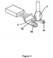
- the second (6b) and third (6c) jet members are placed in substantially perpendicular manner to the length of the ring spinning frame, one each at the sides of the spinning cop (5) in a circumferential manner as shown in figure 3 .
- each of the bottom jet members (2) and an additional jet arrangement (3) are simultaneously or cyclically provided with air / whirling air current to detach the yarn end from the cop (5) and lift the same upstream towards the drafting zone to enable effective automatic yarn piecing with the drafted fibre material.
- the jet members (6a, 6b, 6c) combined with additional jet (3) are worked in the following sequence to achieve successful detaching and lifting of the broken yarn end from the cop (5).
- spindle brake is applied for a predetermined period. Now, the spindle stops rotating.
- the second (6b) and third (6c) jet members (side jets) combined with additional jet members (3) are made to purge air jets for a fraction of second.
- spindle brake is relieved for a predetermined period. Now, the spindle starts rotating.
- the first (6a) jet member (front jet) is made to purge air jet through the plurality of orifices (7) for a fraction of second.
- the additional jet arrangement (3) is activated simultaneously with every possible sequence as explained above.
- the additional jet arrangement (3) with at least three blow nozzles (9a, 9b, 9c) are provided with air current to blow air towards the cop (5).
- the additional jet arrangement (3) is positioned in a region proximity to the ring rail (8) such that it purges air tangentially in upward direction towards the cop (5).
- the additional jet arrangement is provided with three blow nozzles (9a, 9b, 9c) in which two nozzles (9a, 9b) with outlets project towards the cop surface such that the outlet of said nozzles blows air at an acute angle towards the upward direction of cop or at perpendicular direction to the vertical axis of cop (5) at still further height from the ring rail (8) and another nozzle (9c) points towards the traveller region of the ring (10).
- the additional blow nozzles (9a, 9b, 9c) are mounted in a housing (11) in automatic piecing unit (1).
- All the jet members (6a, 6b, 6c) and blow nozzles (9a, 9b, 9c) are provided with air in different sequences in any cyclic order or simultaneously to successfully lift the broken yarn, particularly with fine counts, greater than 60 Ne, from cop (5).
- the above said bottom circumferential jet arrangement (2) and the additional jet arrangement (3) are configured to be connected to a control unit with a human machine interface and can be controlled to operate at any sequence.
- the timing and sequence of providing the air currents, air flow rate / air pressure and velocity control of all the jet members can be varied according to the broken yarn picking requirement and yarn count through control unit.
- the several operating parameters and the sequences of the jet members and blow nozzles can be stored in the control unit and can be selected in the display unit based on the requirement for each and every spinning machine and also based on the yarn count and yarn type.
- the broken yarn end is detached from the cop (5) and directed upstream.
- the detached broken yarn end is held in the top suction unit placed at the top of the automatic piecing unit in front of the drafting zone of the ring spinning machine.
- the broken yarn end is detached from the spinning cop irrespective of its position anywhere from top to bottom and directed upstream towards the drafting zone successfully. Thereby, the broken yarn is lifted to enable automatic piecing with the drafted material.
- the above sequence takes place simultaneously for every yarn breakage occurrence irrespective of the ring rail position.
- the above described automatic piecing unit for ring spinning machine provides an effective broken yarn end lifting arrangement suitable for fine count yarns.
Abstract
Description
- The present invention generally relates to textile spinning machines. Particularly, the invention relates to an automatic yarn piecing unit for textile ring spinning machines. More particularly, the invention relates to improved broken yarn lifting arrangement in the automatic piecing unit of textile ring spinning machines.
- In textile spinning mills, ring spinning machines are crucial machines used to produce continuous lengths of yarn. Textile roving materials produced from roving frame machines are usually fed into the ring spinning machines. The roving material is first drafted and twisted and then wound on a package so called cop or yarn cop. During this spinning process, yarn breakage in said ring spinning machines is a common and frequent problem that requires continuous attention of the work force. In present day, the yarn breakage remains a major disadvantage in ring spinning machines. Traditionally, large number of workers used to continuously monitor the ring spinning machines usually comprising more than 1600 spindles, throughout the length of the machine frame, which is normally 75 meters long. In addition to periodic monitoring, the broken yarns have to be pieced and the corresponding yarn spinning sequence has to be restarted then and there, in order to avoid wastage of yarn. Since, several ring spinning machines of this kind are installed in one spinning mill close to each other, it becomes tedious for the operator to access the gangways for monitoring the ring spinning machine round the clock.
- To overcome above problems, automatic piecing units are being developed. The automatic piecing unit is in the form of a movable vehicle with wheels/rails/guides. The said piecing unit has in-built drive units, sensing units, and support units. Automatic piecing assembly comprises plurality of modules for broken yarn pickup from cop, yarn inserting into the traveller, yarn suction and yarn piecing at drafting zone etc. The yarn pickup module consists of air blowing means fixedly mounted to the auto piecing unit.
- Such a method and a device for the pneumatic detachment and suction of a broken yarn end is known from
US Patent 4132057 . According to that patent, the intermittent rotation of the spindle is done and air blowing on the broken yarn cop is effected for the purpose of detaching the torn thread end using three blow nozzles with single orifice each. However, the said method in practice does not reliably lifts the broken yarn from the cop. - In another known arrangement as explained in German Patent
DE3012210 , complicated brush or tangential blow nozzle in addition to an axial blow nozzle is used to detach the broken yarn from the cop. However, the said arrangement also fails to lift the broken yarn end from the cop successfully. Also said arrangements have complicated constructional arrangements and requires separate mounting and actuating arrangements. - All the known yarn lifting arrangements fail to lift or detach the fine count yarn from the cop, say Ne>60. The said failing attempts tends to further increased number of attempts with high intensity of compressed air for more time than previous cycles. The said number of attempts leads to higher consumption of compressed air which leads to problem of higher operating costs. Also prolonged blowing effect over the surface of the cops also causes yarn quality deterioration such as hairiness increase in yarn, twists imperfections and neps formation. If air blow is provided with high pressure to lift fine count yarns from cop, the yarn content in cop will collapse. The piecing efficiency of the automatic piecing unit is very much lower in all known broken yarn lifting arrangements. Thus, reduced efficiency of automatic piecing unit affects overall production efficiency of the ring spinning machines in the spinning mills.
- There exists a need for an improved yarn lifting arrangement for detaching all counts of yarn from the cop.
- The present invention provides an improved yarn lifting arrangement for the automatic piecing unit of ring spinning machines, to successfully detach the broken yarn end from cop, with simple and reliable constructional arrangements.
- The main object of the present invention is to provide an improved automatic piecing unit for textile ring spinning machines.
- Another object of the present invention is to provide an improved broken yarn lifting arrangement for automatic piecing unit of textile ring spinning machines.
- Yet another object of the present invention is to provide an improved broken yarn lifting arrangement for successful detaching of broken yarn in automatic piecing units with simple and reliable construction, suitable for lifting fine count yarns.
- According to the invention, the automatic piecing unit is provided for textile ring spinning machines. The automatic piecing unit assists in yarn piecing operation during yarn breakage incidents in ring spinning machines. The proper picking / detaching of the broken yarn end is necessary for the successful piecing of the broken yarn ends. To enable the same, the present invention is provided with bottom circumferential jet with at least three jet members and top additional jet arrangements in the automatic piecing unit. The three jet members in bottom circumferential jet arrangement comprises preferably three orifices each. The number of orifices can also be more than three or less than three. The diameter of the orifice is preferably 2mm. The three jet members in bottom circumferential jet can be operated in any sequence such that only two jets are operated at a time or only one jet is operated at a time or all the three jets are operated at a time, along with the top additional jet arrangements. The bottom jets are operated in any cyclic order either clockwise or anticlockwise one by one. Any of the three jet members can be switched on and switched off based on the requirement of yarn lifting. The additional jet arrangement comprises at least two blowing nozzles, preferably three, facing towards the cop at a certain height above from the bottom circumferential jet. The bottom circumferential jet arrangement is placed in front of the ring rail slightly below the ring rail position such that it purges air towards the cop from plurality of orifices for lifting the broken yarn end from the cop. The additional jet arrangements are positioned in a region proximity to the ring rail at a certain height above from bottom jet, such that the additional jets purges air tangentially in upward direction towards the cop. The additional jet arrangement is provided with three blow nozzles in which two nozzles with outlets project towards the cop surface such that the outlet of said nozzles blows air at an acute angle towards the upward direction of cop or at perpendicular direction to the vertical axis of cop, at still further height from the ring rail and another blow nozzle points towards the traveller region of the ring. The additional blow nozzles are mounted in a housing in the automatic piecing unit. The blow nozzles in additional jet arrangement can be of any size and diameter. The inner diameter of the blow nozzle is preferably in the range of 2 to 4 mm and the outer diameter is preferably in the range of 4 to 6 mm. All the jet members of the bottom circumferential jet and all the blow nozzles of additional jet arrangement are provided with air in different sequences in any cyclic order to successfully lift the broken yarn with fine counts from cop. The three blow nozzles in additional jet arrangement also can be operated in any sequence such that only two nozzles are operated at a time or only one nozzle is operated at a time or all the three nozzles are operated at a time. The three blow nozzles in additional jet arrangement can be operated in any cyclic order. In the additional jet arrangement, one of the blow nozzle serves the purpose of both lifting the broken yarn and also rotating the traveller around the ring by blowing the compressed air during the threading operation of piecing sequence.
- According to an embodiment of the invention, the additional blow nozzles faces various surfaces of cop over the height of cop and the blow nozzles are adjustable in any direction both horizontally and vertically and can be tilted at any angles to blow air towards the cop at any point over and around the cop surface. The bottom circumferential jet arrangement with three jet members of three orifices each, along with the additional jet arrangement with three blow nozzles, blowing air current according to the invention, results in successful lifting of the broken yarn end from the cop. The above said bottom circumferential jet arrangement and the additional jet arrangement are configured to be connected to a control unit with a human machine interface and can be controlled to operate at any sequence. The timing and sequence of providing the air currents, air flow rate / air pressure and velocity control of all the jet members can be varied according to the broken yarn picking requirement and yarn count through control unit. The several operating parameters and the sequences of the jet members and blow nozzles can be stored in the control unit and can be selected in the display unit based on the requirement for each and every spinning machine and also based on the yarn count and yarn type. After successful picking, the detached yarn end is moved upstream into a top suction tube adjacent to the drafting unit, to hold the yarn until piecing with the roving material delivering from drafting zone.
- In one aspect of the present invention, an automatic piecing unit for a textile ring spinning machine is provided. The automatic piecing unit comprises a bottom circumferential jet arrangement having at least three nozzles, each nozzle having a plurality of orifices. The bottom circumferential jet arrangement is disposed concentrically around a spindle of the textile ring spinning machine proximate a cop. Each nozzle project air through the orifice towards cop at an upwards angle. The automatic piecing unit also comprises an additional jet arrangement disposed above the bottom circumferential jet arrangement and having a plurality of blow nozzles. At least two blow nozzles blow air towards the cop of the ring spinning machine. Each of the bottom circumferential jet arrangement and the additional jet arrangement discharge air to detach a broken yarn end from the cop of the ring spinning machine and lift the broken yarn end upstream towards a drafting zone of the ring spinning machine to enable effective automatic yarn piecing with a drafted fibre material.
- According to the present invention, the additional jet arrangement having a plurality of blow nozzles, in which two blow nozzles blow air at an acute angle towards an upward direction of the cop and another blow nozzle points towards a traveler region of a ring of the textile ring spinning machine.
- According to the present invention, each of the bottom circumferential jet arrangement and the additional jet arrangement simultaneously discharge air to detach the broken yarn end from the cop of the ring spinning machine.
- According to the present invention, each of the bottom circumferential jet arrangement and the additional jet arrangement cyclically discharge air to detach the broken yarn end from the cop of the ring spinning machine.
- According to the present invention, each of the bottom circumferential jet arrangement and the additional jet arrangement discharge a whirling air current.
- According to the present invention, two blow nozzles projects air at perpendicular direction to the vertical axis of the cop of the ring spinning machine and another blow nozzle points air towards the traveler region of the ring of the ring spinning machine.
- According to the present invention, each of the bottom circumferential jet arrangement and the additional jet arrangement projects air tangentially and axially in upward direction towards the cop of the ring spinning machine.
- According to the present invention, the blow nozzles of the additional jet arrangement faces various surfaces of the cop over the height of the cop and the blow nozzles are adjustable in any direction both horizontally and vertically and can be tilted at any angles to blow air towards the cop at any point over and around the cop surface.
- According to the present invention, the bottom circumferential jet arrangement and the additional jet arrangement are configured to be connected to a control unit with a human machine interface.
- According to the present invention, several operating parameters, sequence timings and sequence of providing the air currents, air flow rate or air pressure and velocity control of the nozzles of the bottom circumferential jet arrangement and the blow nozzles of the additional jet arrangement are stored in the control unit and can be selected in the display unit based on the requirement for each and every spinning machine and also based on the yarn count and yarn type.
- According to the present invention, the nozzles of the bottom circumferential jet arrangement and the blow nozzles of the additional jet arrangement lifts the broken yarn with fine counts, preferably greater than 60 Ne counts, from the cop of the ring spinning machine.
- According to the present invention, the nozzles of the bottom circumferential jet arrangement and the blow nozzles of the additional jet arrangement are provided with air in different sequences in any cyclic order either clockwise or anticlockwise one by one to lift the broken yarn with fine counts from the cop of the ring spinning machine.
- According to the present invention, the inner diameter of the blow nozzles is preferably in the range of 2 to 4 mm and the outer diameter of the blow nozzles is preferably in the range of 4 to 6 mm.
- According to the present invention, the additional jet arrangement is movable vertically in synchronization with a ring rail of the ring spinning machine.
- According to the present invention, the additional jet arrangement is moved forward through actuating means, which includes at least one of the electric cylinder, pneumatic cylinder or the like.
- According to the present invention, the diameter of the orifices of the bottom circumferential jet arrangement is preferably 2 mm.
- In another aspect of the present invention, a method of detaching and lifting a broken yarn end from a cop of a textile ring spinning machine using an automatic piecing unit is provided. The method comprises step of purging air jets from two side nozzles of a bottom circumferential jet arrangement of the automatic piecing unit on the cop for a predetermined period. The method also comprises step of purging air jets from a plurality of blow nozzles of an additional jet arrangement of the automatic piecing unit on the cop a predetermined period. The method further comprises step of purging air jet from a nozzle of the bottom circumferential jet arrangement of the automatic piecing unit on the cop a predetermined period. The method further comprises step of applying and relieving spindle brake of the cop of ring spinning machine periodically for a predetermined period. The method comprises step of activating the additional jet arrangement to blow air towards the cop in such a manner that two blow nozzles blow air at an acute angle towards an upward direction of the cop and another blow nozzle points towards a traveler region of a ring of the ring spinning machine. Each of the bottom circumferential jet arrangement and the additional jet arrangement are provided with air to detach a broken yarn end from the cop and lift the broken yarn end upstream towards a drafting zone of the ring spinning machine to enable effective automatic yarn piecing with a drafted fibre material.
- According to the present invention, each of the bottom circumferential jet arrangement and the additional jet arrangement simultaneously discharge air to detach the broken yarn end from the cop.
- According to the present invention, each of the bottom circumferential jet arrangement and the additional jet arrangement cyclically discharge air to detach the broken yarn end from the cop of the ring spinning machine.
- According to the present invention, each of the bottom circumferential jet arrangement and the additional jet arrangement discharge a whirling air current.
- According to the present invention, two blow nozzles projects air at perpendicular direction to the vertical axis of the cop and another blow nozzle points air towards the traveler region of the ring of the ring spinning machine.
- According to the present invention, each of the bottom circumferential jet arrangement and the additional jet arrangement projects air tangentially and axially in upward direction towards the cop of the ring spinning machine.
- According to the present invention, several operating parameters, sequence timings and sequence of providing the air currents, air flow rate or air pressure and velocity control of the bottom circumferential jet arrangement and the additional jet arrangement are stored in a control unit and can be selected in a display unit based on the requirement for each and every spinning machine and also based on the yarn count and yarn type.
- According to the present invention, the bottom circumferential jet arrangement and the additional jet arrangement lifts the broken yarn with fine counts preferably greater than 60 Ne, from the cop of the ring spinning machine.
- According to the present invention, the bottom circumferential jet arrangement and the additional jet arrangement are provided with air in different sequences in any cyclic order either clockwise or anticlockwise one by one to lift the broken yarn with fine counts from the cop of the ring spinning machine.
- Other aspects and advantages of the invention will become apparent from the following description, taken in conjunction with the accompanying drawings, illustrating by way of example the principles of the invention.
-
-
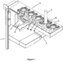
Figures 1 illustrates the schematic view of the bottom circumferential jet arrangement and additional jet arrangement in the automatic piecing unit with winding cop of ring spinning machine in which broken yarn is to be lifted according to the present invention. -
Figure 2 illustrates the side view of the bottom circumferential jet arrangement and additional jet arrangement in the automatic piecing unit with winding cop of ring spinning machine in which broken yarn is to be lifted according to the present invention. -
Figure 3 illustrates the schematic view of the bottom circumferential jet arrangement in the automatic piecing unit for ring spinning machine according to an embodiment of the present invention. -
Figure 3a illustrates the top view of the bottom circumferential jet arrangement in the automatic piecing unit for ring spinning machine according to an embodiment of the present invention. - Referring to
figures 1 to 3 , the automatic piecing unit (1) of the present invention is provided with bottom circumferential jet arrangement (2) and an additional jet arrangement (3). The automatic piecing unit (1) moves longitudinally along the aisle of the ring spinning machine (4). The ring spinning machine (4) is capable of winding yarn onto a bobbin mounted to spinning spindle, so called cop (5). When yarn breakage occurs in the spinning sequence, the broken yarn thread end is stuck in the spinning cop (5). To enable yarn piecing, the yarn end has to be detached from the cop (5). - The automatic piecing unit is provided with a bottom circumferential jet arrangement (2) mounted in the automatic piecing unit. Referring to
Figures 3 and3a , the bottom circumferential jet arrangement (2) is placed concentrically around the spindle with at least three nozzles (6a, 6b, 6c) surrounding the cop (5) at a position below the ring rail (8) to blow air jets. The jet members in bottom circumferential jet (2) comprises three orifices (7) each facing at an acute angle towards the cop (5). The diameter of the orifice is preferably 2mm. - The automatic piecing unit according to the present invention is provided with an additional jet arrangement (3) mounted in the automatic piecing unit (1) as shown in
figures 1 &2 . The said additional jet (3) is moved forward through actuating means. - The actuating means is at least one of the electric cylinder, pneumatic cylinder or the like. Further, the additional jet arrangement (3) is movable vertically in synchronization with the ring rail (8) of ring spinning machine (4). The controlled movement of the said additional jet arrangement (3) with respect to ring rail (8) is performed by suitable sensors and actuators, preferably electric type. The actuators can also be one of pneumatic, hydraulic, linear, etc. The additional jet arrangement (3) is provided with at least two, preferably three substantially cylindrical and slender blow nozzles (9a, 9b, 9c). The three blow nozzles (9a, 9b, 9c) altogether serves the purpose of lifting the broken yarn from the cop (5) by blowing the compressed air tangentially and axially towards the cop (5) with broken yarn end. As an embodiment, the additional blow nozzles (9a, 9b, 9c) faces various surfaces of cop (5) over the height of cop (5) and the blow nozzles (9a, 9b, 9c) are adjustable in any direction both horizontally and vertically and can be tilted at any angles to blow air towards the cop (5) at any point over and around the cop surface. In the additional jet arrangement (3) with three blow nozzles (9a, 9b, 9c), two nozzles (9a, 9b) with outlets projects towards the cop surface such that the outlet of said nozzles blows air at an acute angle towards the upward direction of cop (5) or at perpendicular direction to the vertical axis of cop (5), at still further height from the ring rail (8) and another blow nozzle (9c) points towards the traveller region of the ring (10). The additional blow nozzles (9a, 9b, 9c) are mounted in a housing (11) in the automatic piecing unit (1). The blow nozzles in additional jet arrangement can be of any size and diameter. The inner diameter of the blow nozzle (9) is preferably in the range of 2 to 4 mm and the outer diameter is preferably in the range of 4 to 6 mm. All the jet members (6a, 6b, 6c) of the bottom circumferential jet (2) and all the blow nozzles (9a, 9b, 9c) of additional jet arrangement (3) are provided with air in different sequences in any cyclic order to successfully lift the broken yarn with fine counts from cop (5) and also the blow nozzles can be provided with air current simultaneously. The three blow nozzles (9a, 9b, 9c) in additional jet arrangement (3) can be operated in any sequence such that only two nozzles are operated at a time or only one nozzle is operated at a time or all the three nozzles are operated at a time. The blow nozzle (9c) of the additional jet arrangement (3) pointing towards the ring traveller also serves the purpose of blowing the traveller around the ring (10) during the threading operation. After threading the yarn end into the traveler of ring (10), the said yarn held in the top suction tube is pieced with delivery yarn from drafting zone of ring spinning machine (4). Before initiating piecing, the broken yarn spindle is braked, the broken yarn end is lifted from the cop (5) and held inside the top suction tube. The top suction tube then moves upstream near the drafting zone of ring spinning machine (4) for subsequent piecing with delivering fibre.
- Referring to
Figure 3 , the bottom circumferential jet arrangement (2) is positioned concentrically around the cop (5) of the spindle in proximity to the ring rail (8) of ring spinning machine (4) slightly below the ring rail position. The additional jet arrangement (3) with three blow nozzles (9a, 9b, 9c) is placed in front of the broken yarn cop (5) proximity to the ring rail (8) at a certain height above the bottom jet (2). The broken yarn thread normally tangles with the wound yarn in the cop (5) at any portion from top to bottom of the cop (5) which cannot be adjudged precisely. The circumferential bottom jet arrangement (2) is provided as separate jet members, preferably three separate jet members (6a, 6b, 6c) with three orifices (7) each deriving air from air sources. The first jet member (6a) is placed in front of the spinning cop (5) in substantially parallel manner to the length of the ring spinning frame. The second (6b) and third (6c) jet members are placed in substantially perpendicular manner to the length of the ring spinning frame, one each at the sides of the spinning cop (5) in a circumferential manner as shown infigure 3 . According to the invention, each of the bottom jet members (2) and an additional jet arrangement (3) are simultaneously or cyclically provided with air / whirling air current to detach the yarn end from the cop (5) and lift the same upstream towards the drafting zone to enable effective automatic yarn piecing with the drafted fibre material. - According to an embodiment of the invention, the jet members (6a, 6b, 6c) combined with additional jet (3) are worked in the following sequence to achieve successful detaching and lifting of the broken yarn end from the cop (5). Firstly, spindle brake is applied for a predetermined period. Now, the spindle stops rotating. During that time, the second (6b) and third (6c) jet members (side jets) combined with additional jet members (3) are made to purge air jets for a fraction of second. Subsequently, spindle brake is relieved for a predetermined period. Now, the spindle starts rotating. During that time, the first (6a) jet member (front jet) is made to purge air jet through the plurality of orifices (7) for a fraction of second. The additional jet arrangement (3) is activated simultaneously with every possible sequence as explained above. The additional jet arrangement (3) with at least three blow nozzles (9a, 9b, 9c) are provided with air current to blow air towards the cop (5). The additional jet arrangement (3) is positioned in a region proximity to the ring rail (8) such that it purges air tangentially in upward direction towards the cop (5). The additional jet arrangement is provided with three blow nozzles (9a, 9b, 9c) in which two nozzles (9a, 9b) with outlets project towards the cop surface such that the outlet of said nozzles blows air at an acute angle towards the upward direction of cop or at perpendicular direction to the vertical axis of cop (5) at still further height from the ring rail (8) and another nozzle (9c) points towards the traveller region of the ring (10). The additional blow nozzles (9a, 9b, 9c) are mounted in a housing (11) in automatic piecing unit (1). All the jet members (6a, 6b, 6c) and blow nozzles (9a, 9b, 9c) are provided with air in different sequences in any cyclic order or simultaneously to successfully lift the broken yarn, particularly with fine counts, greater than 60 Ne, from cop (5).
- The above said bottom circumferential jet arrangement (2) and the additional jet arrangement (3) are configured to be connected to a control unit with a human machine interface and can be controlled to operate at any sequence. The timing and sequence of providing the air currents, air flow rate / air pressure and velocity control of all the jet members can be varied according to the broken yarn picking requirement and yarn count through control unit. The several operating parameters and the sequences of the jet members and blow nozzles can be stored in the control unit and can be selected in the display unit based on the requirement for each and every spinning machine and also based on the yarn count and yarn type.
- As a result of the above said action, the broken yarn end is detached from the cop (5) and directed upstream. The detached broken yarn end is held in the top suction unit placed at the top of the automatic piecing unit in front of the drafting zone of the ring spinning machine.
- As a result of the above explained sequences, the broken yarn end is detached from the spinning cop irrespective of its position anywhere from top to bottom and directed upstream towards the drafting zone successfully. Thereby, the broken yarn is lifted to enable automatic piecing with the drafted material. The above sequence takes place simultaneously for every yarn breakage occurrence irrespective of the ring rail position.
- Thus, the above described automatic piecing unit for ring spinning machine provides an effective broken yarn end lifting arrangement suitable for fine count yarns.
- In view of the present disclosure which describes the present invention, all changes, modifications and variations within the meaning and range of equivalency are considered within the scope and spirit of the invention.
Claims (15)
- An automatic piecing unit (1) for a textile ring spinning machine (4), the automatic piecing unit (1) comprising:a bottom circumferential jet arrangement (2) having at least three nozzles (6a, 6b, 6c), each nozzle (6a, 6b, 6c) having a plurality of orifices (7), the bottom circumferential jet arrangement (2) is disposed concentrically around a spindle of the textile ring spinning machine (4) proximate a cop (5), each nozzle (6a, 6b, 6c) project air through the orifice towards cop (5) at an upwards angle;an additional jet arrangement (3) disposed above the bottom circumferential jet arrangement (2) and having a plurality of blow nozzles (9a, 9b, 9c), wherein at least two blow nozzles (9a, 9b) blow air towards the cop (5) of the ring spinning machine (4),each of the bottom circumferential jet arrangement (2) and the additional jet arrangement (3) discharge air to detach a broken yarn end from the cop (5) of the ring spinning machine (4) and lift the broken yarn end upstream towards a drafting zone of the ring spinning machine (4) to enable effective automatic yarn piecing with a drafted fibre material.
- The automatic piecing unit (1) as claimed in claim 1, wherein the additional jet arrangement (3) having a plurality of blow nozzles (9a, 9b, 9c), in which two blow nozzles (9a, 9b) projects air at perpendicular direction to the vertical axis of the cop (5) of the ring spinning machine (4) and blows air at an acute angle towards an upward direction of the cop (5) and another blow nozzle (9c) points towards a traveler region of a ring (10) of the the textile ring spinning machine (4).
- The automatic piecing unit (1) as claimed in claim 1, wherein each of the bottom circumferential jet arrangement (2) and the additional jet arrangement (3) simultaneously or cyclically discharge a whirling air current to detach the broken yarn end from the cop (5) of the ring spinning machine (4).
- The automatic piecing unit (1) as claimed in preceding claims 1 to 3, wherein each of the bottom circumferential jet arrangement (2) and the additional jet arrangement (3) projects air tangentially and axially in upward direction towards the cop (5) of the ring spinning machine (4).
- The automatic piecing unit (1) as claimed in claims 1 and 2, wherein the blow nozzles (9a, 9b, 9c) of the additional jet arrangement (3) faces various surfaces of the cop (5) over the height of the cop (5) and the blow nozzles (9a, 9b, 9c) are adjustable in any direction both horizontally and vertically and can be tilted at any angles to blow air towards the cop (5) at any point over and around the cop surface.
- The automatic piecing unit (1) as claimed in claims 1 and 2, wherein the bottom circumferential jet arrangement (2) and the additional jet arrangement (3) are configured to be connected to a control unit with a human machine interface and wherein several operating parameters, sequence timings and sequence of providing the air currents, air flow rate or air pressure and velocity control of the nozzles (6a, 6b, 6c) of the bottom circumferential jet arrangement (2) and the blow nozzles (9a, 9b, 9c) of the additional jet arrangement (3) are stored in the control unit and can be selected in the display unit based on the requirement for each and every spinning machine and also based on the yarn count and yarn type.
- The automatic piecing unit (1) as claimed in claims 1 and 2, wherein the nozzles (6a, 6b, 6c) of the bottom circumferential jet arrangement (2) and the blow nozzles (9a, 9b, 9c) of the additional jet arrangement (3) lifts the broken yarn with fine counts, preferably greater than 60 Ne, from the cop (5) of the ring spinning machine (4).
- The automatic piecing unit (1) as claimed in claims 1 and 2, wherein the nozzles (6a, 6b, 6c) of the bottom circumferential jet arrangement (2) and the blow nozzles (9a, 9b, 9c) of the additional jet arrangement (3) are provided with air in different sequences in any cyclic order either clockwise or anticlockwise one by one to lift the broken yarn with fine counts from the cop (5) of the ring spinning machine (4).
- The automatic piecing unit (1) as claimed in claim 2, wherein the inner diameter of the blow nozzles (9a, 9b, 9c) is preferably in the range of 2 to 4 mm and the outer diameter of the blow nozzles (9a, 9b, 9c) is preferably in the range of 4 to 6 mm.
- The automatic piecing unit (1) as claimed in claim 1, wherein the additional jet arrangement (3) is movable vertically in synchronization with a ring rail (8) of the ring spinning machine (4) and wherein the additional jet arrangement (3) is moved forward through actuating means, which includes at least one of the electric cylinder, pneumatic cylinder or the like.
- The automatic piecing unit (1) as claimed in claim 1, wherein the diameter of the orifices (7) of the bottom circumferential jet arrangement (2) is preferably 2 mm.
- A method of detaching and lifting a broken yarn end from a cop (5) of a textile ring spinning machine (4) using an automatic piecing unit (1), the method comprising steps of:purging air jets from two side nozzles (6b, 6c) of a bottom circumferential jet arrangement (2) of the automatic piecing unit (1) on the cop (5) for a predetermined period;purging air jets from a plurality of blow nozzles (9a, 9b, 9c) of an additional jet arrangement (3) of the automatic piecing unit (1) on the cop (5) for a predetermined period;purging air jet from a nozzle (6a) of the bottom circumferential jet arrangement (2) of the automatic piecing unit (1) on the cop (5) for a predetermined period;applying and relieving spindle brake of the cop (5) of ring spinning machine (4) periodically for a predetermined period;activating the additional jet arrangement (3) to blow air towards the cop (5) in such a manner that two blow nozzles (9a, 9b) projects air at perpendicular direction to the vertical axis of the cop (5) and blows air at an acute angle towards an upward direction of the cop (5) and another blow nozzle (9c) points towards a traveler region of a ring (10) of the ring spinning machine (4),each of the bottom circumferential jet arrangement (2) and the additional jet arrangement (3) are provided with air to detach a broken yarn end from the cop (5) and lift the broken yarn end upstream towards a drafting zone of the ring spinning machine (4) to enable effective automatic yarn piecing with a drafted fibre material.
- The method as claimed in claim 12, wherein each of the bottom circumferential jet arrangement (2) and the additional jet arrangement (3) simultaneously or cyclically discharge a whirling air current to detach the broken yarn end from the cop (5) of the ring spinning machine (4).
- The method as claimed in claim 12, wherein the bottom circumferential jet arrangement (2) and the additional jet arrangement (3) lifts the broken yarn with fine counts preferably greater than 60 Ne, from the cop (5) of the ring spinning machine (4).
- The method as claimed in claim 12, wherein the bottom circumferential jet arrangement (2) and the additional jet arrangement (3) are provided with air in different sequences in any cyclic order either clockwise or anticlockwise one by one to lift the broken yarn with fine counts from the cop (5) of the ring spinning machine (4).
Applications Claiming Priority (1)
| Application Number | Priority Date | Filing Date | Title |
|---|---|---|---|
| IN202241015703 | 2022-03-22 |
Publications (1)
| Publication Number | Publication Date |
|---|---|
| EP4249655A1 true EP4249655A1 (en) | 2023-09-27 |
Family
ID=85556495
Family Applications (1)
| Application Number | Title | Priority Date | Filing Date |
|---|---|---|---|
| EP23160704.5A Pending EP4249655A1 (en) | 2022-03-22 | 2023-03-08 | An improved yarn lifting arrangement in automatic piecing unit of ring spinning machine |
Country Status (2)
| Country | Link |
|---|---|
| EP (1) | EP4249655A1 (en) |
| CN (1) | CN116791248A (en) |
Citations (6)
| Publication number | Priority date | Publication date | Assignee | Title |
|---|---|---|---|---|
| US4132057A (en) | 1975-10-01 | 1979-01-02 | Zinser Textilmaschinen Gmbh | Process and apparatus for pneumatic separation and aspiration of broken thread ends |
| DE3012210A1 (en) | 1980-03-28 | 1981-10-08 | Zinser Textilmaschinen Gmbh, 7333 Ebersbach | Method of detaching broken thread ends from thread spool - using intermittent turning process together with axial blowing directed at thread |
| EP0417618A2 (en) * | 1989-09-15 | 1991-03-20 | Zinser Textilmaschinen GmbH | Method and apparatus for pneumatically removing a broken yarn end from the winding of a yarn winding member |
| JPH07278975A (en) * | 1994-04-08 | 1995-10-24 | Ishikawa Seisakusho Ltd | Method for picking up yarn end of end broken bobbin in automatic piecing device of spinning frame |
| DE19501464C1 (en) * | 1995-01-19 | 1996-05-23 | Zinser Textilmaschinen Gmbh | Appts. for automatic elimination of yarn breakages in ring spinning machines |
| EP3556918A1 (en) * | 2018-04-20 | 2019-10-23 | Lakshmi Machine Works Ltd. | Yarn lifting arrangement for piecing unit and a method thereof |
-
2023
- 2023-03-08 EP EP23160704.5A patent/EP4249655A1/en active Pending
- 2023-03-17 CN CN202310268674.9A patent/CN116791248A/en active Pending
Patent Citations (6)
| Publication number | Priority date | Publication date | Assignee | Title |
|---|---|---|---|---|
| US4132057A (en) | 1975-10-01 | 1979-01-02 | Zinser Textilmaschinen Gmbh | Process and apparatus for pneumatic separation and aspiration of broken thread ends |
| DE3012210A1 (en) | 1980-03-28 | 1981-10-08 | Zinser Textilmaschinen Gmbh, 7333 Ebersbach | Method of detaching broken thread ends from thread spool - using intermittent turning process together with axial blowing directed at thread |
| EP0417618A2 (en) * | 1989-09-15 | 1991-03-20 | Zinser Textilmaschinen GmbH | Method and apparatus for pneumatically removing a broken yarn end from the winding of a yarn winding member |
| JPH07278975A (en) * | 1994-04-08 | 1995-10-24 | Ishikawa Seisakusho Ltd | Method for picking up yarn end of end broken bobbin in automatic piecing device of spinning frame |
| DE19501464C1 (en) * | 1995-01-19 | 1996-05-23 | Zinser Textilmaschinen Gmbh | Appts. for automatic elimination of yarn breakages in ring spinning machines |
| EP3556918A1 (en) * | 2018-04-20 | 2019-10-23 | Lakshmi Machine Works Ltd. | Yarn lifting arrangement for piecing unit and a method thereof |
Also Published As
| Publication number | Publication date |
|---|---|
| CN116791248A (en) | 2023-09-22 |
Similar Documents
| Publication | Publication Date | Title |
|---|---|---|
| US9103053B2 (en) | Method for operating an open-end rotor spinning machine | |
| CN109072493B (en) | Processing method for spinning and/or twisting yarn, machine for spinning and/or twisting yarn and method for modifying machine | |
| JP6635686B2 (en) | Semi-automatic twill winding package manufacturing textile machine | |
| US4944145A (en) | Spinning machine for producing feeding packages for twisting | |
| CN107829173B (en) | Ring spinning machine and spinning method using the same | |
| CN1267592C (en) | Method and device for spinning with a suppressed yarn balloon | |
| CN101265623A (en) | Device for automatic spinning start in an open-end spinning machine | |
| EP3156526B1 (en) | Hollow guide shaft, air-jet spinning device, and textile machinery | |
| EP4249655A1 (en) | An improved yarn lifting arrangement in automatic piecing unit of ring spinning machine | |
| EP3736361B1 (en) | Yarn suction arrangement for piecing unit of a textile machine | |
| EP3556918A1 (en) | Yarn lifting arrangement for piecing unit and a method thereof | |
| EP1726695B1 (en) | Core yarn production method and apparatus | |
| EP2985371B1 (en) | Spinning machine | |
| US20020124545A1 (en) | Spinning machine | |
| CN106400215B (en) | Nozzle block, air spinning device and spinning machine | |
| US5005348A (en) | Process and an arrangement for producing packages | |
| CN113201813A (en) | Spinning method for independent winding and spinning machine | |
| US20190323151A1 (en) | Yarn-Forming Element for a Roving Machine as well as a Roving Machine Equipped Therewith | |
| CN110029412B (en) | Spinning machine and spinning method | |
| CN107829180B (en) | Spindle rail for ring spinning machine | |
| EP3643819A1 (en) | Yarn picking arrangement for a ring spinning machine and a method thereof | |
| EP3438334B1 (en) | Air spinning machine and display control method | |
| JPH04300329A (en) | Method for spinning fiber bundle and fine spinning machine | |
| EP3178974B1 (en) | Method for preparing a workstation for the resumption of the spinning process on an air-jet spinning machine and an air-jet spinning machine for performing the method | |
| CN217052531U (en) | Fiber strip supporting device and ring spinning machine |
Legal Events
| Date | Code | Title | Description |
|---|---|---|---|
| PUAI | Public reference made under article 153(3) epc to a published international application that has entered the european phase |
Free format text: ORIGINAL CODE: 0009012 |
|
| STAA | Information on the status of an ep patent application or granted ep patent |
Free format text: STATUS: THE APPLICATION HAS BEEN PUBLISHED |
|
| AK | Designated contracting states |
Kind code of ref document: A1 Designated state(s): AL AT BE BG CH CY CZ DE DK EE ES FI FR GB GR HR HU IE IS IT LI LT LU LV MC ME MK MT NL NO PL PT RO RS SE SI SK SM TR |
|
| STAA | Information on the status of an ep patent application or granted ep patent |
Free format text: STATUS: REQUEST FOR EXAMINATION WAS MADE |
|
| 17P | Request for examination filed |
Effective date: 20240311 |
|
| RBV | Designated contracting states (corrected) |
Designated state(s): AL AT BE BG CH CY CZ DE DK EE ES FI FR GB GR HR HU IE IS IT LI LT LU LV MC ME MK MT NL NO PL PT RO RS SE SI SK SM TR |