EP4249423A1 - Hydraulisches steuerungssystem eines hubantriebs eines hubgerüstes eines flurförderzeugs und flurförderzeug - Google Patents
Hydraulisches steuerungssystem eines hubantriebs eines hubgerüstes eines flurförderzeugs und flurförderzeug Download PDFInfo
- Publication number
- EP4249423A1 EP4249423A1 EP23159620.6A EP23159620A EP4249423A1 EP 4249423 A1 EP4249423 A1 EP 4249423A1 EP 23159620 A EP23159620 A EP 23159620A EP 4249423 A1 EP4249423 A1 EP 4249423A1
- Authority
- EP
- European Patent Office
- Prior art keywords
- valve
- lifting
- control system
- pressure
- lowering
- Prior art date
- Legal status (The legal status is an assumption and is not a legal conclusion. Google has not performed a legal analysis and makes no representation as to the accuracy of the status listed.)
- Granted
Links
Images

Classifications
-
- F—MECHANICAL ENGINEERING; LIGHTING; HEATING; WEAPONS; BLASTING
- F15—FLUID-PRESSURE ACTUATORS; HYDRAULICS OR PNEUMATICS IN GENERAL
- F15B—SYSTEMS ACTING BY MEANS OF FLUIDS IN GENERAL; FLUID-PRESSURE ACTUATORS, e.g. SERVOMOTORS; DETAILS OF FLUID-PRESSURE SYSTEMS, NOT OTHERWISE PROVIDED FOR
- F15B21/00—Common features of fluid actuator systems; Fluid-pressure actuator systems or details thereof, not covered by any other group of this subclass
- F15B21/08—Servomotor systems incorporating electrically operated control means
- F15B21/087—Control strategy, e.g. with block diagram
-
- B—PERFORMING OPERATIONS; TRANSPORTING
- B66—HOISTING; LIFTING; HAULING
- B66F—HOISTING, LIFTING, HAULING OR PUSHING, NOT OTHERWISE PROVIDED FOR, e.g. DEVICES WHICH APPLY A LIFTING OR PUSHING FORCE DIRECTLY TO THE SURFACE OF A LOAD
- B66F9/00—Devices for lifting or lowering bulky or heavy goods for loading or unloading purposes
- B66F9/06—Devices for lifting or lowering bulky or heavy goods for loading or unloading purposes movable, with their loads, on wheels or the like, e.g. fork-lift trucks
- B66F9/075—Constructional features or details
- B66F9/20—Means for actuating or controlling masts, platforms, or forks
- B66F9/22—Hydraulic devices or systems
-
- B—PERFORMING OPERATIONS; TRANSPORTING
- B66—HOISTING; LIFTING; HAULING
- B66F—HOISTING, LIFTING, HAULING OR PUSHING, NOT OTHERWISE PROVIDED FOR, e.g. DEVICES WHICH APPLY A LIFTING OR PUSHING FORCE DIRECTLY TO THE SURFACE OF A LOAD
- B66F3/00—Devices, e.g. jacks, adapted for uninterrupted lifting of loads
- B66F3/24—Devices, e.g. jacks, adapted for uninterrupted lifting of loads fluid-pressure operated
-
- F—MECHANICAL ENGINEERING; LIGHTING; HEATING; WEAPONS; BLASTING
- F15—FLUID-PRESSURE ACTUATORS; HYDRAULICS OR PNEUMATICS IN GENERAL
- F15B—SYSTEMS ACTING BY MEANS OF FLUIDS IN GENERAL; FLUID-PRESSURE ACTUATORS, e.g. SERVOMOTORS; DETAILS OF FLUID-PRESSURE SYSTEMS, NOT OTHERWISE PROVIDED FOR
- F15B11/00—Servomotor systems without provision for follow-up action; Circuits therefor
- F15B11/16—Servomotor systems without provision for follow-up action; Circuits therefor with two or more servomotors
- F15B11/161—Servomotor systems without provision for follow-up action; Circuits therefor with two or more servomotors with sensing of servomotor demand or load
- F15B11/165—Servomotor systems without provision for follow-up action; Circuits therefor with two or more servomotors with sensing of servomotor demand or load for adjusting the pump output or bypass in response to demand
-
- F—MECHANICAL ENGINEERING; LIGHTING; HEATING; WEAPONS; BLASTING
- F15—FLUID-PRESSURE ACTUATORS; HYDRAULICS OR PNEUMATICS IN GENERAL
- F15B—SYSTEMS ACTING BY MEANS OF FLUIDS IN GENERAL; FLUID-PRESSURE ACTUATORS, e.g. SERVOMOTORS; DETAILS OF FLUID-PRESSURE SYSTEMS, NOT OTHERWISE PROVIDED FOR
- F15B13/00—Details of servomotor systems ; Valves for servomotor systems
- F15B13/02—Fluid distribution or supply devices characterised by their adaptation to the control of servomotors
- F15B13/024—Pressure relief valves
-
- F—MECHANICAL ENGINEERING; LIGHTING; HEATING; WEAPONS; BLASTING
- F15—FLUID-PRESSURE ACTUATORS; HYDRAULICS OR PNEUMATICS IN GENERAL
- F15B—SYSTEMS ACTING BY MEANS OF FLUIDS IN GENERAL; FLUID-PRESSURE ACTUATORS, e.g. SERVOMOTORS; DETAILS OF FLUID-PRESSURE SYSTEMS, NOT OTHERWISE PROVIDED FOR
- F15B13/00—Details of servomotor systems ; Valves for servomotor systems
- F15B13/02—Fluid distribution or supply devices characterised by their adaptation to the control of servomotors
- F15B13/06—Fluid distribution or supply devices characterised by their adaptation to the control of servomotors for use with two or more servomotors
-
- F—MECHANICAL ENGINEERING; LIGHTING; HEATING; WEAPONS; BLASTING
- F15—FLUID-PRESSURE ACTUATORS; HYDRAULICS OR PNEUMATICS IN GENERAL
- F15B—SYSTEMS ACTING BY MEANS OF FLUIDS IN GENERAL; FLUID-PRESSURE ACTUATORS, e.g. SERVOMOTORS; DETAILS OF FLUID-PRESSURE SYSTEMS, NOT OTHERWISE PROVIDED FOR
- F15B20/00—Safety arrangements for fluid actuator systems; Applications of safety devices in fluid actuator systems; Emergency measures for fluid actuator systems
- F15B20/008—Valve failure
Definitions
- the invention relates to a hydraulic control system of a lifting drive of a mast of an industrial truck, wherein the control system has a control directional valve device which is connected to a delivery line of a hydraulic pump, to a container line led to a container and to a connecting line led to the lifting drive, the control directional valve device being formed is to control the lifting operation and the lowering operation of the hoist drive.
- control directional valve device is provided to control the lifting operation and the lowering operation of the lifting drive of the mast of the industrial truck.
- the lifting drive consists of one or more hydraulic lifting cylinders, which raise and lower a load-carrying device, for example a load fork, which can be raised and lowered on the mast.
- a load located on the load-carrying device is supported on the control directional valve device.
- a fault in the control directional valve device in such a hydraulic control system in lowering operation while lowering a load for example with a nominal load
- the control directional valve device is suddenly actuated into a neutral position or a blocking position, in which the connection of the lifting drive to the container is blocked.
- Such a fault in the control directional valve device can occur in the case of a control directional valve device that is controlled and actuated electrically by means of an electrical actuating device, for example in the event of a power failure in the electrical control signal of the actuating device and/or due to a plug tearing of an electrical cable that is connected to the electrical actuating device of the control directional valve device and the control signal of the Actuating device leads to occur.
- the maximum lowering speed of the load handling device is usually ⁇ 0.6 m/s. Due to changed legal regulations, maximum lowering speeds of greater than 1 m/s, for example 1.2 m/s, are enabled and used in current industrial trucks.
- the maximum lowering or lifting speed of the load-carrying device is generally increased
- Load-carrying means to maximum lifting speeds and/or lowering speeds of the load-carrying means in the range of greater than 1 m/s, for example 1.2 m/s to reinforce the mechanical mast structure of the mast so that component failure of the mast can be ruled out in the above-mentioned error case.
- reinforcing the mechanical mast structure of the mast is disadvantageous because it is very expensive.
- the present invention is based on the object of providing a hydraulic control system and an industrial truck with a hydraulic control system which is improved with regard to the disadvantage mentioned.
- control system has a pressure safety valve which is assigned to the connecting line, whereby the pressure safety valve is designed to limit a pressure peak introduced into the mast in the event of a fault in the control directional valve device.
- An error case of the control directional valve device is to be viewed in particular as an error case of the control directional valve device, in which the control directional valve device is suddenly actuated, i.e. in a short period of time of a few milliseconds, into a neutral position or a blocking position, in which the connection of the lifting drive to the container line or the delivery line is locked and thus the lifting or lowering movement of the lifting drive and thus of the load-carrying device is suddenly stopped.
- An error case of the control directional valve device in the sense of the application is therefore considered in particular to be an error case of the control directional valve device, which leads to a sudden stop of the lifting movement or lowering movement of the lifting drive. This is also referred to below as an error case in the control directional valve device, which leads to a digital lifting stop or digital lowering stop.
- Such an error case of the control directional valve device which leads to a digital lifting stop or a digital lowering stop, occurs in particular in the case of a control directional valve device that is controlled and actuated electrically by means of an electrical actuating device, for example in the event of a power failure in the electrical control signal of the actuating device and / or due to a plug break in an electrical cable on, which is connected to the electrical actuation device of the control directional valve device and carries the control signal of the actuation device.
- the pressure safety valve assigned to the connecting line is provided for such an error, which limits the pulse introduced into the mast by limiting the pressure peak in the event of such an error.
- the pressure safety valve is connected to the connecting line on the input side and is connected to the container on the output side.
- a connection between the connecting line and the container can be established, in particular to limit the pressure peak.
- the pressure safety valve is designed in particular to limit the pressure peak introduced into the mast in the event of a fault in the control directional valve device by connecting the connecting line to the container.
- the pressure safety valve in particular opens and establishes a connection between the connecting line and the container.
- the pressure safety valve has a blocking position and an open position, the pressure safety valve being acted upon by a spring device in the direction of the blocking position and by the pressure present in the connecting line in the direction of the open position. This in particular ensures that the pressure safety valve is actuated directly into the open position by the pressure present in the connecting line against the force of the spring device in order to limit the pressure peak introduced into the mast.
- the pressure safety valve in particular is designed as a pressure relief valve.
- a pressure safety valve can be provided with little construction effort.
- the pressure safety valve is in particular designed as a control valve, in particular a two-position control valve.
- the control valve is designed in particular as a two-port, two-position valve. With such a control valve, a pressure safety valve can be provided with little construction effort.
- control valve in particular is designed as a switching valve or as a proportional valve that throttles in intermediate positions.
- the spring device can be set to an opening pressure of the pressure safety valve that is greater than the maximum system pressure of the lifting drive.
- the spring device can be set to an opening pressure of the pressure safety valve that is greater than 100% or 110% or 120% of the maximum system pressure of the lifting drive.
- the spring device is set to an opening pressure of the pressure safety valve which is greater than 120% of the maximum system pressure of the lifting drive, preferably greater than 330 bar.
- control system in particular has a pressure limiting device, which is connected to the delivery line on the input side and is designed to secure the maximum system pressure of the lifting drive.
- a pressure limiting device connected to the delivery line, the maximum system pressure of the lifting drive can be secured and limited in a simple manner.
- control directional valve device in particular is electrically actuated.
- control directional valve device comprises a control directional valve which has a neutral position, a lowering position and a lifting position, the control directional valve being actuated by a spring device into the neutral position, by means of a first electrical actuating device, in particular a magnet, in the direction of the lowering position can be actuated and can be actuated in the direction of the lifting position by means of a second electrical actuating device, in particular a magnet.
- a control directional valve the lifting operation and the lowering operation of the lifting drive can be controlled with just a single control directional valve.
- control directional valve device in particular comprises a lifting valve and a lowering valve, the lowering valve having a blocking position and a lowering position, the lowering valve being actuated by a spring device in the direction of the blocking position and by means of an electrical actuating device, in particular a magnet , can be actuated in the direction of the lowering position, and wherein the lifting valve has a blocking position and a lifting position, wherein the lifting valve is actuated by a spring device in the direction of the blocking position and can be actuated in the direction of the lifting position by means of an electrical actuating device, in particular a magnet.
- control directional valve device which has a lifting valve for controlling the lifting operation of the lifting drive and a lowering valve for controlling the lowering operation of the lifting drive
- the lifting operation and the lowering operation of the lifting drive can be controlled with a simply constructed lifting valve and a simply constructed lowering valve.
- the invention further relates to an industrial truck, in particular a counterbalance forklift or reach truck, with a mast comprising a lifting drive and a hydraulic control system according to the invention.
- the invention has a number of advantages.
- the inventive limitation of the pressure peak occurring through the pressure safety valve in the event of a fault in the control directional valve device, which leads to a digital lifting stop or a digital lowering stop, can result in a reinforcement of the mechanical mast structure of the mast when increasing the maximum lifting speeds and/or lowering speeds of the load-carrying means a range of greater than 1 m/s, for example 1.2 m/s, can be dispensed with. This makes it possible to achieve cost savings.
- a reduction in variants of the lifting masts is possible if different design variants of industrial trucks with different maximum lifting speeds and / or lowering speeds of the load handling device in the range of 0.6 m / s and in the range of 1.2 m / s are to be produced, since the design variant of an industrial truck with a maximum lifting speed and/or lowering speed of the load handling device in the range of 0.6m/s and the design variant of an industrial truck with a maximum lifting speed and/or lowering speed of the load handling device in the range of 1.2m/s can be equipped with the same lifting frame.
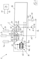
- FIG. 1 A circuit diagram of a hydraulic control system 1 according to the invention of a lifting drive 2 of a lifting frame (not shown) of an industrial truck (not shown) is shown.
- the control system 1 of the Figures 1 and 2 comprises a control directional valve device 5, which is designed to control the lifting operation and the lowering operation of the lifting drive 2.
- the lifting drive 2 comprises a plurality of hydraulic lifting cylinders 3a, 3b, 3c.
- the lifting cylinders 3a, 3b are designed, for example, as mast lifting cylinders.
- the lifting cylinder 3c is designed, for example, as a free-lift cylinder.
- the lifting frame not shown in more detail, consists, for example, of a standing mast and one or more extension masts that can be raised relative to the standing mast, as well as a load-carrying device which is arranged in a liftable manner in the extension mast that extends the highest.
- the lifting cylinders 3a, 3b designed as mast lifting cylinders are designed to raise and lower the extension mast or masts relative to the stationary mast of the mast.
- the lifting cylinder 3c designed as a free-lift cylinder, is designed to raise and lower the load-carrying device in the highest extending extension mast.
- the control directional valve device 5 is connected to a delivery line 10 of a hydraulic pump 11, to a container line 13 led to a container 12 and to a connecting line 14 led to the lifting drive 2.
- the hydraulic pump 11 is designed as a hydraulic pump operated in an open circuit, which sucks in pressure medium from the container 12 by means of a suction line 15 and conveys it into the delivery line 10.
- control directional valve device 5 is part of a directional valve block 16, in which further ones are included, not shown in more detail
- Control directional valves which are connected to the delivery line 10 and the container line 13 and control additional hydraulic consumers of the industrial truck, for example a tilt drive and / or a side shift device of the mast or the load handler, can be arranged.
- control directional valve device 5 includes a lifting valve 20 and a lowering valve 21.
- the sink valve 21 is connected to the connecting line 14 and the container line 13.
- the lowering valve 21 has a blocking position 21a and a lowering position 21b. In the blocking position 21a, the connection between the connecting line 14 and the container line 13 is blocked. In the open position 21b, the connecting line 14 is connected to the container line 13.
- the sink valve 21 is provided with a leak-tight blocking position 21a, in which a check valve 22 that blocks in the direction of the container line 13 is effective.
- the lowering valve 21 can be operated electrically.
- the lowering valve 21 is actuated by a spring device 23 in the direction of the blocking position 21a and can be actuated in the direction of the lowering position 21b by means of an electrical actuating device 24, for example a magnet.
- the lifting valve 20 is connected to the delivery line 10 and the connecting line 14.
- the lifting valve 20 has a blocking position 20a and a lifting position 20b. In the blocking position 20a, the connection between the delivery line 10 and the connecting line 14 is blocked off. In the open position 20b, the delivery line 10 is connected to the connecting line 14.
- the lifting valve 20 can be operated electrically.
- the lifting valve 20 is actuated by a spring device 25 in the direction of the blocking position 20a and can be actuated in the direction of the lifting position 20b by means of an electrical actuating device 26, for example a magnet.
- a control device 30, for example an electronic control device 30, is provided, which is connected to the electrical actuating devices 24, 26 of the control directional valve device 5 by means of electrical cables 31, 32.
- the control directional valve device 5 is activated, corresponding control signals are carried in the electrical cables 31, 32, which act on the actuating devices 24, 26.
- a pressure limiting device 36 is arranged, which is connected on the input side to the delivery line 10 and is acted upon by a spring 37 in a blocking position and by the pressure present in the delivery line 10 in an open position.
- the pressure limiting device 6 serves to safeguard the maximum system pressure of the lifting drive 2, for example the maximum permissible delivery pressure of the hydraulic pump 11 or the limitation of the nominal load of the lifting drive 2.
- the opening pressure of the pressure limiting device 6 predetermined by the spring 37 and thus the maximum system pressure of the lifting drive 2 is, for example set to a value of 280 bar.
- the control system 1 has Figures 1 and 2 a pressure safety valve 40, which is assigned to the connecting line 14.
- the pressure safety valve 40 is designed to limit a pressure peak introduced into the mast in the event of a fault in the control directional valve device 5.
- the pressure safety valve 40 is connected to the connecting line 14 on the input side and is connected to the container 12 on the output side.
- the pressure safety valve 40 is arranged in particular in a connecting line 51 led from the connecting line 14 to the container 12.
- the pressure safety valve 40 is thus arranged and connected in parallel to the control directional valve device 5.
- the pressure safety valve 40 has a blocking position 40a and an open position 40b, with the pressure safety valve 40 being moved by a spring device 41 in the direction of Blocking position and is acted upon by the pressure in the connecting line 14 in the direction of the open position.
- the pressure safety valve 40 is designed as a pressure relief valve 42.
- the pressure safety valve 40 is designed as a control valve 43, for example a two-position control valve.
- control valve 43 is designed as a proportional valve that throttles in intermediate positions.
- control valve 43 can be designed as a switching valve.
- the opening pressure of the pressure safety valve 40 specified by the spring device 41 is preferably set to a value that is greater than 120% of the maximum system pressure of the lifting drive 2. For example, if the system pressure of the lifting drive secured with the pressure limiting device 36 is 280 bar, the pressure safety valve 40 is preferably set to an opening pressure that is greater than 330 bar.
- the lifting or lowering operation of the lifting drive 2 is controlled by appropriately controlling the lifting valve 20 or the lowering valve 21.
- the maximum system pressure is secured by the pressure limiting device 36.
- the pressure safety valve 40 whose opening pressure preferably corresponds to at least 120% of the maximum system pressure secured at the pressure limiting device 36, is therefore not used to protect the maximum system pressure in normal operation when lifting and lowering the lifting drive 2, so that the pressure safety valve 40 is not used in normal operation and is not forced into the open position during normal operation.
- the control system 1 is preferably designed such that the maximum lifting speeds and/or lowering speeds of the lifting drive 2 controlled load-carrying means in the range of greater than 1 m/s, for example 1.2 m/s.
- a fault in the control directional valve device 5 can occur, in which the lifting valve 20 or the lowering valve 21 is suddenly actuated by the corresponding spring device 25 or 23 into the blocking position 20a or 21a and thus the lifting movement or lowering movement of the load-carrying means controlled by the lifting drive 2 is stopped suddenly, for example within a few milliseconds.
- An error case of the control directional valve device 5 in the sense of the application is therefore particularly considered to be an error case of the control directional valve device 5, which leads to a sudden stop of the lifting movement or lowering movement of the lifting drive 2. This is also referred to below as an error case of the control directional valve device 5, which leads to a digital lifting stop or digital lowering stop.
- the load on the load-carrying device is suddenly stopped and, depending on the previous lifting or lowering speed of the load-carrying device and the weight of the load picked up on the load-carrying device, an impulse in the form of a pressure peak is introduced into the mast.
- the pressure safety valve 40 responds and is opened into the open position by the pressure in the connecting line 14 against the force of the spring device 41.
- the pressure safety valve 40 which is opened into the open position, limits the impulse introduced onto the mast by limiting the pressure peak. A component failure of the mast in the event of an error that leads to a digital Lifting stop or leading to a digital lowering stop can therefore be prevented in a simple manner without reinforcing the mechanical mast structure of the mast with the pressure safety valve 40 according to the invention.
Landscapes
- Engineering & Computer Science (AREA)
- Mechanical Engineering (AREA)
- General Engineering & Computer Science (AREA)
- Fluid Mechanics (AREA)
- Physics & Mathematics (AREA)
- Chemical & Material Sciences (AREA)
- Structural Engineering (AREA)
- Transportation (AREA)
- Geology (AREA)
- Life Sciences & Earth Sciences (AREA)
- Analytical Chemistry (AREA)
- Civil Engineering (AREA)
- Combustion & Propulsion (AREA)
- Forklifts And Lifting Vehicles (AREA)
- Control And Safety Of Cranes (AREA)
Abstract
Description
- Die Erfindung betrifft ein hydraulisches Steuerungssystem eines Hubantriebs eines Hubgerüstes eines Flurförderzeugs, wobei das Steuerungssystem eine Steuerwegeventileinrichtung aufweist, die mit einer Förderleitung einer Hydraulikpumpe, mit einer zu einem Behälter geführten Behälterleitung und mit einer zu dem Hubantrieb geführten Verbindungsleitung in Verbindung steht, wobei die Steuerwegeventileinrichtung ausgebildet ist, den Hebenbetrieb und den Senkenbetrieb des Hubantriebs zu steuern.
- Bei derartigen hydraulischen Steuerungssystemen ist die Steuerwegeventileinrichtung vorgesehen, den Hebenbetrieb und den Senkenbetrieb des Hubantriebs des Hubgerüstes des Flurförderzeugs zu steuern. Der Hubantrieb besteht aus einem oder mehreren hydraulischen Hubzylindern, die ein an dem Hubgerüst anhebbar und absenkbar angeordnetes Lastaufnahmemittel, beispielsweise eine Lastgabel, anheben und absenken. Eine auf dem Lastaufnahmemittel befindliche Last stützt sich auf der Steuerwegeventileinrichtung ab.
- Erfolgt bei einem derartigen hydraulischen Steuerungssystem im Senkenbetrieb während des Absenkens einer Last, beispielsweise mit Nennlast, ein Fehlerfall der Steuerwegeventileinrichtung, wird die Steuerwegeventileinrichtung schlagartig in eine Neutralstellung bzw. eine Sperrstellung betätigt, in der die Verbindung des Hubantriebs mit dem Behälter abgesperrt ist. Ein derartiger Fehlerfall der Steuerwegeventileinrichtung kann bei einem elektrisch, mittels einer elektrischen Betätigungseinrichtung angesteuerten und betätigten Steuerwegeventileinrichtung beispielsweise bei einem Stromausfall des elektrischen Ansteuersignals der Betätigungseinrichtung und/oder durch einen Steckerabriss eines elektrischen Kabels, das mit der elektrischen Betätigungseinrichtung der Steuerwegeventileinrichtung verbunden ist und das Ansteuersignal der Betätigungseinrichtung führt, auftreten. Infolge der schlagartigen Betätigung der Steuerwegeventileinrichtung in die Neutralstellung bzw. die Sperrstellung bei einem derartigen Fehlerfall der Steuerwegeventileinrichtung wird die Last auf dem Lastaufnahmemittel schlagartig angehalten und je nach vorangegangener Senkengeschwindigkeit des Lastaufnahmemittels und Gewicht der auf dem Lastaufnahmemittel aufgenommen Last wird ein Impuls über eine Druckspitze in das Hubgerüst eingeleitet.
- Bei bekannten Flurförderzeugen beträgt in der Regel die max. Senkengeschwindigkeit des Lastaufnahmemittels <0,6 m/s. Aufgrund geänderter gesetzlicher Vorschriften werden in aktuellen Flurförderzeugen max. Senkengeschwindigkeiten von größer 1 m/s, beispielsweise 1,2m/s, ermöglicht und eingesetzt.
- Insbesondere bei Flurförderzeugen, die maximale Hebengeschwindigkeiten und/oder Senkengeschwindigkeiten des Lastaufnahmemittels im Bereich von größer 1 m/s, beispielsweise 1,2 m/s, aufweisen, wird bei einem derartigen Fehlerfall, beispielsweise bei einem Steckerabriss eines elektrischen Kabels, das mit der elektrischen Betätigungseinrichtung der Steuerwegeventileinrichtung verbunden ist und das Ansteuersignal der Betätigungseinrichtung führt, beim Senken des Lastaufnahmemittels ein großer Impuls in Form einer Druckspitze in das Hubgerüst eingeleitet. Aus diesem Grund ist bei Flurförderzeugen, die maximale Hebengeschwindigkeiten und/oder Senkengeschwindigkeiten des Lastaufnahmemittels im Bereich von größer 1 m/s, beispielsweise 1,2 m/s, aufweisen, in der Regel mit der Anhebung der maximalen Senken- bzw. auch Hebengeschwindigkeit des Lastaufnahmemittels auf maximale Hebengeschwindigkeiten und/oder Senkengeschwindigkeiten des Lastaufnahmemittels im Bereich von größer 1 m/s, beispielsweise 1,2 m/s, eine Verstärkung der mechanischen Maststruktur des Hubgerüsts vorzunehmen, damit ein Bauteilversagen des Hubgerüsts bei dem oben genannten Fehlerfall ausgeschlossen werden kann. Eine Verstärkung der mechanischen Maststruktur des Hubgerüstes ist jedoch nachteilig, da dies sehr kostenaufwendig ist.
- Der vorliegenden Erfindung liegt die Aufgabe zugrunde, ein hydraulisches Steuerungssystem und ein Flurförderzeug mit einem hydraulischen Steuerungssystem zur Verfügung zu stellen, das hinsichtlich des genannten Nachteils verbessert ist.
- Diese Aufgabe wird erfindungsgemäß dadurch gelöst, dass das Steuerungssystem ein Druckabsicherungsventil aufweist, das der Verbindungsleitung zugeordnet ist, wobei das Druckabsicherungsventil ausgebildet ist, bei einem Fehlerfall der Steuerwegeventileinrichtung eine in das Hubgerüst eingeleitete Druckspitze zu begrenzen.
- Ein Fehlerfall der Steuerwegeventileinrichtung ist insbesondere ein Fehlerfall der Steuerwegeventileinrichtung anzusehen, bei dem die Steuerwegeventileinrichtung schlagartig, d.h. in einer kurzen Zeitspanne von wenigen Millisekunden, in eine Neutralstellung bzw. eine Sperrstellung betätigt wird, in der die Verbindung des Hubantriebs mit der Behälterleitung bzw. der Förderleitung abgesperrt ist und somit die Heben- bzw. Senkenbewegung des Hubantriebs und somit des Lastaufnahmemittels schlagartig angehalten wird. Infolge der schlagartigen Betätigung der Steuerwegeventileinrichtung in die Neutralstellung bzw. die Sperrstellung bei einem derartigen Fehlerfall der Steuerwegeventileinrichtung wird die Last auf dem Lastaufnahmemittel schlagartig angehalten und je nach vorangegangener Senkengeschwindigkeit des Lastaufnahmemittels und Gewicht der auf dem Lastaufnahmemittel aufgenommen Last ein Impuls in Form einer Druckspitze in das Hubgerüst eingeleitet.
- Als Fehlerfall der Steuerwegeventileinrichtung im Sinne der Anmeldung wird somit insbesondere ein Fehlerfall der Steuerwegeventileinrichtung angesehen, der zu einem schlagartigen Stopp der Hebenbewegung bzw. Senkenbewegung des Hubantriebs führt. Dies wird im Folgenden auch bezeichnet als Fehlerfall der Steuerwegeventileinrichtung, der zu einem digitalen Hebenstopp bzw. digitalen Senkenstopp führt.
- Ein derartiger Fehlerfall der Steuerwegeventileinrichtung, der zu einem digitalen Hebenstopp bzw. einem digitalen Senkenstopp führt, tritt insbesondere bei einem elektrisch, mittels einer elektrischen Betätigungseinrichtung angesteuerten und betätigten Steuerwegeventileinrichtung beispielsweise bei einem Stromausfall des elektrischen Ansteuersignals der Betätigungseinrichtung und/oder durch einen Steckerabriss eines elektrischen Kabels auf, das mit der elektrischen Betätigungseinrichtung der Steuerwegeventileinrichtung verbunden ist und das Ansteuersignal der Betätigungseinrichtung führt.
- Erfindungsgemäß ist für einen derartigen Fehlerfall das der Verbindungsleitung zugeordnete Druckabsicherungsventil vorgesehen, das bei einem derartigen Fehlerfall den in das Hubgerüst eingeleiteten Impuls durch eine Begrenzung der Druckspitze begrenzt. Durch die Verwendung des erfindungsgemäßen Druckabsicherungsventil kann somit auf eine aufwändige Verstärkung der mechanischen Maststruktur des Hubgerüsts verzichtet werden, um ein Bauteilversagen des Hubgerüsts bei dem oben genannten Fehlerfall auszuschließen.
- Gemäß einer vorteilhaften Ausgestaltungsform der Erfindung ist insbesondere das Druckbabsicherungsventil eingangsseitig mit der Verbindungsleitung verbunden und ausgangsseitig mit dem Behälter verbunden. Beim Öffnen des Druckabsicherungsventils kann somit insbesondere zur Begrenzung der Druckspitze eine Verbindung der Verbindungsleitung mit dem Behälter hergestellt werden.
- Gemäß einer vorteilhaften Ausgestaltungsform der Erfindung ist insbesondere das Druckabsicherungsventil ausgebildet, bei dem Fehlerfall der Steuerwegeventileinrichtung durch Verbinden der Verbindungsleitung mit dem Behälter die in das Hubgerüst eingeleitete Druckspitze zu begrenzen. Zur Begrenzung der Druckspitze öffnet somit insbesondere das Druckabsicherungsventil und stellt eine Verbindung der Verbindungsleitung mit dem Behälter her.
- Gemäß einer vorteilhaften Ausgestaltungsform der Erfindung weist insbesondere das Druckabsicherungsventil eine Sperrstellung und eine Öffnungsstellung auf, wobei das Druckabsicherungsventil von einer Federeinrichtung in Richtung der Sperrstellung und von dem in der Verbindungsleitung anstehenden Druck in Richtung der Öffnungsstellung beaufschlagt ist. Hierdurch wird insbesondere erzielt, dass das Druckabsicherungsventil direkt von dem in der Verbindungsleitung anstehenden Druck entgegen der Kraft der Federeinrichtung in die Öffnungsstellung betätigt wird, um die in das Hubgerüst eingeleitete Druckspitze zu begrenzen.
- Gemäß einer vorteilhaften Ausgestaltungsform der Erfindung ist insbesondere das Druckabsicherungsventil als Druckbegrenzungsventil ausgebildet. Mit einem Druckbegrenzungsventil kann ein Druckabsicherungsventil bei geringem Bauaufwand zur Verfügung gestellt werden.
- Gemäß einer vorteilhaften Ausgestaltungsform der Erfindung ist insbesondere das Druckabsicherungsventil als Steuerventil, insbesondere Zweistellungsteuerventil, ausgebildet ist. Das Steuerventil ist insbesondere als Zweianschluss-Zweistellungventil ausgebildet. Mit einem derartigen Steuerventil kann ein Druckabsicherungsventil bei geringem Bauaufwand zur Verfügung gestellt werden.
- Gemäß einer vorteilhaften Ausführungsform der Erfindung ist insbesondere das Steuerventil als Schaltventil oder als in Zwischenstellungen drosselndes Proportionalventil ausgebildet.
- Besonders bevorzugt kann die Federeinrichtung auf einen Öffnungsdruck des Druckabsicherungsventils eingestellt der größer als der maximale Systemdruck des Hubantriebs sein. Insbesondere bevorzugt kann Federeinrichtung auf einen Öffnungsdruck des Druckabsicherungsventils eingestellt, der größer als 100% oder 110 % oder 120% des maximalen Systemdrucks des Hubantriebs ist.
- Gemäß einer vorteilhaften Ausgestaltungsform der Erfindung ist insbesondere die Federeinrichtung auf einen Öffnungsdruck des Druckabsicherungsventils eingestellt, der größer als 120% des maximalen Systemdrucks des Hubantriebs ist, bevorzugt größer als 330 bar ist. Mit einer derartigen Einstellung des Öffnungsdruckes des Druckabsicherungsventils wird erzielt, dass das Druckabsicherungsventil nicht zur Absicherung des maximalen Systemdrucks des Hubantriebs dient und somit im normalen Betrieb beim Heben und Senken des Lastaufnahmemittels nicht anspricht, sondern nur im Fehlerfall der Steuerwegeventileinrichtung anspricht und in die Öffnungsstellung betätigt wird, um die in das Hubgerüst eingeleitete Druckspitze zu begrenzen.
- Gemäß einer vorteilhaften Ausgestaltungsform der Erfindung weist insbesondere das Steuerungssystem eine Druckbegrenzungseinrichtung auf, die eingangsseitig mit der Förderleitung verbunden ist und ausgebildet ist, den maximalen Systemdrucks des Hubantriebs abzusichern. Mit einer derartigen, an die Förderleitung angeschlossenen Druckbegrenzungseinrichtung kann in einfacher Weise der maximale Systemdruck des Hubantriebs abgesichert und begrenzt werden.
- Gemäß einer vorteilhaften Ausgestaltungsform der Erfindung ist insbesondere die Steuerwegeventileinrichtung elektrisch betätigt.
- Gemäß einer vorteilhaften Ausführungsform der Erfindung umfasst insbesondere die Steuerwegeventileinrichtung ein Steuerwegeventil, das eine Neutralstellung, eine Senkenstellung und eine Hebenstellung aufweist, wobei das Steuerwegeventil von einer Federeinrichtung in die Neutralstellung betätigt ist, mittels einer ersten elektrischen Betätigungseinrichtung, insbesondere eines Magneten, in Richtung der Senkenstellung betätigbar ist und mittels einer zweiten elektrischen Betätigungseinrichtung, insbesondere eines Magneten, in Richtung der Hebenstellung betätigbar ist. Mit einem derartigen Steuerwegeventil kann mit nur einem einzigen Steuerwegeventil der Hebenbetrieb und der Senkenbetrieb des Hubantriebs gesteuert werden.
- Gemäß einer alternativen und ebenfalls vorteilhaften Ausführungsform der Erfindung umfasst insbesondere die Steuerwegeventileinrichtung ein Hebenventil und ein Senkenventil, wobei das Senkenventil eine Sperrstellung und eine Senkenstellung aufweist, wobei das Senkenventil von einer Federeinrichtung in Richtung der Sperrstellung betätigt ist und mittels einer elektrischen Betätigungseinrichtung, insbesondere eines Magneten, in Richtung der Senkenstellung betätigbar ist, und wobei das Hebenventil eine Sperrstellung und eine Hebenstellung aufweist, wobei das Hebenventil von einer Federeinrichtung in Richtung der Sperrstellung betätigt ist und mittels einer elektrischen Betätigungseinrichtung, insbesondere eines Magneten, in Richtung der Hebenstellung betätigbar ist. Mit einem derartigen Steuerwegeventileinrichtung, die ein Hebenventil zur Steuerung des Hebenbetriebs des Hubantriebs und ein Senkenventil zur Steuerung des Senkenbetrieb des Hubantriebs aufweist, kann mit einem einfach aufgebauten Hebenventil und einem einfach aufgebauten Senkenventil der Hebenbetrieb und der Senkenbetrieb des Hubantriebs gesteuert werden.
- Die Erfindung betrifft weiterhin ein Flurförderzeug, insbesondere Gegengewichtsgabelstapler oder Schubmaststapler, mit einem einen Hubantrieb umfassenden Hubgerüst und einem erfindungsgemäßen hydraulischen Steuerungssystem.
- Die Erfindung weist eine Reihe von Vorteilen auf.
- Durch die erfindungsgemäße Begrenzung der im Fehlerfall der Steuerwegeventileinrichtung, der zu einem digitalen Hebenstopp bzw. zu einem digitalen Senkenstopp führt, auftretenden Druckspitze durch das Druckabsicherungsventil kann auf eine Verstärkung der mechanischen Maststruktur des Hubgerüsts bei der Anhebung der maximalen Hebengeschwindigkeiten und/oder Senkengeschwindigkeiten des Lastaufnahmemittels in einen Bereich von größer 1 m/s, beispielsweise 1,2 m/s, verzichtet werden. Hierdurch ist eine Kosteneinsparung erzielbar.
- Durch den Entfall einer Verstärkung der mechanischen Maststruktur des Hubgerüst tritt zudem keine zusätzliche Sichteinschränkung einer Bedienperson des Flurförderzeugs bei der Durchsicht durch das Hubgerüst auf.
- Zudem ist eine Variantenreduzierung der Hubgerüste möglich, wenn unterschiedliche Ausführungsvarianten von Flurförderzeugen mit unterschiedlichen maximalen Hebengeschwindigkeiten und/oder Senkengeschwindigkeiten des Lastaufnahmemittels im Bereich von 0,6m/s und im Bereich von 1 ,2m/s hergestellt werden sollen, da die Ausführungsvariante eines Flurförderzeugs mit einer maximalen Hebengeschwindigkeiten und/oder Senkengeschwindigkeiten des Lastaufnahmemittels im Bereich von 0,6m/s und die Ausführungsvariante eines Flurförderzeugs mit einer maximalen Hebengeschwindigkeiten und/oder Senkengeschwindigkeiten des Lastaufnahmemittels im Bereich von 1,2m/s mit denselben Hubgerüstes ausgestattet werden können.
- Weitere Vorteile und Einzelheiten der Erfindung werden beispielhaft anhand der in den schematischen Figuren dargestellten Ausführungsbeispielen näher erläutert. Hierbei zeigt
- Figur 1
- eine erste Ausführungsform eines erfindungsgemäßen hydraulischen Steuerungssystems eines Hubantriebs und
- Figur 2
- eine zweite Ausführungsform eines erfindungsgemäßen hydraulischen Steuerungssystems eines Hubantriebs.
- In der
Figur 1 und derFigur 2 ist jeweils ein Schaltplan eines erfindungsgemäßen hydraulischen Steuerungssystem 1 eines Hubantriebs 2 eines nicht näher dargestellten Hubgerüstes eines nicht näher dargestellten Flurförderzeugs dargestellt. - Gleiche Bauteile sind hierbei in den
Figuren 1 und2 mit gleichen Bezugsziffern versehen. - Das Steuerungssystem 1 der
Figuren 1 und2 umfasst eine Steuerwegeventileinrichtung 5, die ausgebildet ist, den Hebenbetrieb und den Senkenbetrieb des Hubantriebs 2 zu steuern. - In den dargestellten Ausführungsbeispielen umfasst der Hubantrieb 2 mehrere hydraulische Hubzylinder 3a, 3b, 3c. Die Hubzylinder 3a, 3b sind beispielsweise als Masthubzylinder ausgebildet. Der Hubzylinder 3c ist beispielsweise als Freihubzylinder ausgebildet. Das nicht näher dargestellte Hubgerüst besteht beispielsweise aus einem Standmast und einem oder mehreren relativ zum Standmast anhebbaren Ausfahrmasten sowie einem Lastaufnahmemittel, das in dem am höchsten ausfahrenden Ausfahrmast anhebbar angeordnet ist. Die als Masthubzylinder ausgebildeten Hubzylinder 3a, 3b sind ausgebildet, den Ausfahrmast oder die Ausfahrmaste relativ zu dem Standmast des Hubgerüstes anzuheben und abzusenken. Der als Freihubzylinder ausgebildete Hubzylinder 3c ist ausgebildet, das Lastaufnahmemittel in dem am höchsten ausfahrenden Ausfahrmast anzuheben und abzusenken.
- Die Steuerwegeventileinrichtung 5 steht mit einer Förderleitung 10 einer Hydraulikpumpe 11, mit einer zu einem Behälter 12 geführten Behälterleitung 13 und mit einer zu dem Hubantrieb 2 geführten Verbindungsleitung 14 in Verbindung.
- Die Hydraulikpumpe 11 ist in den dargestellten Ausführungsbeispielen als im offenen Kreislauf betriebene Hydraulikpumpe ausgebildet, die mittels einer Ansaugleitung 15 Druckmittel aus dem Behälter 12 ansaugt und in die Förderleitung 10 fördert.
- Die Steuerwegeventileinrichtung 5 ist in den dargestellten Ausführungsbeispielen Bestandteil eines Wegeventilblocks 16, in den weitere, nicht näher dargestellte Steuerwegeventile, die mit der Förderleitung 10 und der Behälterleitung 13 verbunden sind und hydraulische Zusatzverbraucher des Flurförderzeugs steuern, beispielsweise einen Neigeantrieb und/oder eine Seitenschiebereinrichtung des Hubgerüstes bzw. des Lastaufnahmemittels, angeordnet sein können.
- Die Steuerwegeventileinrichtung 5 umfasst in den dargestellten Ausführungsbeispielen ein Hebenventil 20 und ein Senkenventil 21.
- Das Senkenventil 21 ist mit der Verbindungsleitung 14 und der Behälterleitung 13 verbunden. Das Senkenventil 21 weist eine Sperrstellung 21a und eine Senkenstellung 21b auf. In der Sperrstellung 21a ist die Verbindung der Verbindungsleitung 14 mit der Behälterleitung 13 abgesperrt. In der Öffnungsstellung 21b ist die Verbindungsleitung 14 mit der Behälterleitung 13 verbunden. In den dargestellten Ausführungsbeispielen ist das Senkenventil 21 mit einer leckagedichten Sperrstellung 21a versehen, in der ein in Richtung zur Behälterleitung 13 sperrendes Rückschlagventil 22 wirksam ist.
- Das Senkenventil 21 ist elektrisch betätigbar. In den dargestellten Ausführungsbeispielen ist das Senkenventil 21 von einer Federeinrichtung 23 in Richtung der Sperrstellung 21a betätigt und mittels einer elektrischen Betätigungseinrichtung 24, beispielsweise eines Magneten, in Richtung der Senkenstellung 21b betätigbar.
- Das Hebenventil 20 ist mit der Förderleitung 10 und der Verbindungsleitung 14 verbunden. Das Hebenventil 20 weist eine Sperrstellung 20a und eine Hebenstellung 20b auf. In der Sperrstellung 20a ist die Verbindung Förderleitung 10 mit der Verbindungsleitung 14 abgesperrt. In der Öffnungsstellung 20b ist die Förderleitung 10 mit der Verbindungsleitung 14 verbunden.
- Das Hebenventil 20 ist elektrisch betätigbar. In den dargestellten Ausführungsbeispielen ist das Hebenventil 20 von einer Federeinrichtung 25 in Richtung der Sperrstellung 20a betätigt ist und mittels einer elektrischen Betätigungseinrichtung 26, beispielsweise eines Magneten, in Richtung der Hebenstellung 20b betätigbar.
- Zur Ansteuerung der Steuerwegeventileinrichtung 5 ist eine Steuereinrichtung 30, beispielsweise eine elektronische Steuereinrichtung 30, vorgesehen, die mittels elektrischer Kabel 31, 32 mit den elektrischen Betätigungseinrichtungen 24, 26 der Steuerwegeventileinrichtung 5 verbunden ist. In den elektrischen Kabeln 31, 32 werden bei einer Ansteuerung der Steuerwegeventileinrichtung 5 entsprechende Ansteuersignale geführt, die die Betätigungseinrichtungen 24, 26 beaufschlagen.
- In einer von der Förderleitung 10 zum Behälter 12 geführten Leitung 35 ist eine Druckbegrenzungseinrichtung 36 angeordnet, die eingangsseitig mit der Förderleitung 10 verbunden ist und von einer Feder 37 in eine Sperrstellung und von dem in der Förderleitung 10 anstehenden Druck in eine Öffnungsstellung beaufschlagt ist. Die Druckbegrenzungseinrichtung 6 dient zur Absicherung des maximalen Systemdrucks des Hubantriebs 2, beispielsweise des maximalen zulässigen Förderdrucks der Hydraulikpumpe 11 oder der Begrenzung der Nennlast des Hubantriebs 2. Der von der Feder 37 vorgegebene Öffnungsdruck des Druckbegrenzungseinrichtung 6 und somit der maximale Systemdruck des Hubantriebs 2 ist beispielsweise auf einen Wert von 280 bar eingestellt.
- Erfindungsgemäß weist das Steuerungssystem 1 der
Figuren 1 und2 ein Druckabsicherungsventil 40 auf, das der Verbindungsleitung 14 zugeordnet ist. Das Druckabsicherungsventil 40 ist ausgebildet, bei einem Fehlerfall der Steuerwegeventileinrichtung 5 eine in das Hubgerüst eingeleitete Druckspitze zu begrenzen. - Das Druckabsicherungsventil 40 ist in den dargestellten Ausführungsbeispielen eingangsseitig mit der Verbindungsleitung 14 verbunden und ausgangsseitig mit dem Behälter 12 verbunden. Das Druckabsicherungsventil 40 ist hierzu insbesondere in einer von der Verbindungsleitung 14 zu dem Behälter 12 geführten Verbindungsleitung 51 angeordnet. Das Druckabsicherungsventil 40 ist somit parallel zu der Steuerwegeventileinrichtung 5 angeordnet und geschaltet.
- Das Druckabsicherungsventil 40 weist in den dargestellten Ausführungsbeispielen eine Sperrstellung 40a und eine Öffnungsstellung 40b auf, wobei das Druckabsicherungsventil 40 von einer Federeinrichtung 41 in Richtung der Sperrstellung und von dem in der Verbindungsleitung 14 anstehenden Druck in Richtung der Öffnungsstellung beaufschlagt ist.
- In dem Ausführungsbeispiel der
Figur 1 ist das Druckabsicherungsventil 40 als Druckbegrenzungsventil 42 ausgebildet. - In dem Ausführungsbeispiel der
Figur 2 ist das Druckabsicherungsventil 40 als Steuerventil 43, beispielsweise Zweistellungsteuerventil, ausgebildet. - In dem Ausführungsbeispiel der
Figur 2 ist das Steuerventil 43 als in Zwischenstellungen drosselndes Proportionalventil ausgebildet. Alternativ kann das Steuerventil 43 als Schaltventil ausgebildet sein. - Der von der Federeinrichtung 41 vorgegebene Öffnungsdruck des Druckabsicherungsventils 40 ist bevorzugt auf einen Wert eingestellt, der größer als 120% des maximalen Systemdrucks des Hubantriebs 2 ist. Beträgt beispielsweise der mit dem Druckbegrenzungseinrichtung 36 abgesicherte Systemdruck des Hubantriebs 280 bar, ist das Druckabsicherungsventils 40 bevorzugt auf einen Öffnungsdruck eingestellt, der größer als 330 bar ist.
- Im Normalbetrieb des Steuerungssystems 1 der
Figuren 1 und2 wird durch entsprechende Ansteuerung des Hebenventils 20 bzw. des Senkenventils 21 der Heben- bzw. Senkenbetrieb des Hubantriebs 2 gesteuert. Im Normalbetrieb des Steuerungssystems 1 wird der maximale Systemdruck von der Druckbegrenzungseinrichtung 36 abgesichert. Das Druckabsicherungsventil 40, dessen Öffnungsdruck bevorzugt mindestens 120% des maximalen, an der Druckbegrenzungseinrichtung 36 abgesicherten Systemdrucks entspricht, dient somit nicht zur Absicherung des maximalen Systemdrucks im Normalbetrieb beim Heben und Senken des Hubanriebs 2, so dass das Druckabsicherungsventil 40 im Normalbetrieb nicht zum Einsatz kommt und im Normalbetrieb nicht in die Öffnungsstellung beaufschlagt wird. - Das Steuerungssystem 1 ist bevorzugt derart ausgelegt, dass die maximale Hebengeschwindigkeiten und/oder Senkengeschwindigkeiten des von dem Hubantrieb 2 gesteuerten Lastaufnahmemittels im Bereich von größer 1 m/s, beispielsweise 1,2 m/s, beträgt.
- Im Hebenbetrieb oder Senkenbetrieb des Hubantriebs 2 kann ein Fehlerfall der Steuerwegeventileinrichtung 5 auftreten, bei dem das Hebenventil 20 bzw. das Senkenventil 21 schlagartig von der entsprechenden Federeinrichtung 25 bzw. 23 in die Sperrstellung 20a bzw. 21a betätigt wird und somit die Hebenbewegung bzw. Senkenbewegung des von dem Hubantrieb 2 gesteuerten Lastaufnahmemittels schlagartig, beispielsweise innerhalb weniger Millisekunden, beendet wird. Als Fehlerfall der Steuerwegeventileinrichtung 5 im Sinne der Anmeldung wird somit insbesondere ein Fehlerfall der Steuerwegeventileinrichtung 5 angesehen, der zu einem schlagartigen Stopp der Hebenbewegung bzw. Senkenbewegung des Hubantriebs 2 führt. Dies wird im Folgenden auch bezeichnet als Fehlerfall der Steuerwegeventileinrichtung 5, der zu einem digitalen Hebenstopp bzw. digitalen Senkenstopp führt.
- Ein derartiger Fehlerfall der Steuerwegeventileinrichtung 5, der zu einem digitalen Hebenstopp bzw. einem digitalen Senkenstopp führt, ist insbesondere ein Stromausfall der Steuereinrichtung 30 und/oder ein Steckerabriss des elektrischen Kabels 31 bzw. 32. Infolge der schlagartigen Betätigung des Hebenventils 20 bzw. des Senkenventils 21 in die Sperrstellung 20a bzw. 21a bei einem derartigen Fehlerfall wird die Last auf dem Lastaufnahmemittel schlagartig angehalten und je nach vorangegangener Heben- bzw. Senkengeschwindigkeit des Lastaufnahmemittels und Gewicht der auf dem Lastaufnahmemittel aufgenommen Last ein Impuls in Form einer Druckspitze in das Hubgerüst eingeleitet.
- Bei einem derartigen Fehlerfall, der zu einem schlagartigen Stopp der Hebenbewegung bzw. Senkenbewegung des Hubantriebs 2 führt, spricht das erfindungsgemäße Druckabsicherungsventil 40 an und wird von dem in der Verbindungsleitung 14 anstehenden Druck entgegen der Kraft der Federeinrichtung 41 in die Öffnungsstellung aufgesteuert. Das in die Öffnungsstellung aufgesteuerte Druckabsicherungsventil 40 limitiert hierbei bei einem derartigen Fehlerfall, der zu einem schlagartigen Stopp der Hebenbewegung bzw. Senkenbewegung des Hubantriebs 2 führt, durch die Begrenzung der Druckspitze den auf das Hubgerüst eingeleiteten Impuls. Ein Bauteilversagen des Hubgerüsts bei einem Fehlerfall, der zu einem digitalen Hebenstopp bzw. zu einem digitalen Senkenstopp führt, kann somit ohne Verstärkung der mechanischen Maststruktur des Hubgerüsts mit dem erfindungsgemäßen Druckabsicherungsventil 40 in einfacher Weise verhindert werden.
Claims (13)
- Hydraulisches Steuerungssystem (1) eines Hubantriebs (2) eines Hubgerüstes eines Flurförderzeugs, wobei das Steuerungssystem (1) eine Steuerwegeventileinrichtung (5) aufweist, die mit einer Förderleitung (10) einer Hydraulikpumpe (11), mit einer zu einem Behälter (12) geführten Behälterleitung (13) und mit einer zu dem Hubantrieb (2) geführten Verbindungsleitung (2) in Verbindung steht, wobei die Steuerwegeventileinrichtung (5) ausgebildet ist, den Hebenbetrieb und den Senkenbetrieb des Hubantriebs (2) zu steuern, dadurch gekennzeichnet, dass das Steuerungssystem (1) ein Druckabsicherungsventil (40) aufweist, das der Verbindungsleitung (14) zugeordnet ist, wobei das Druckabsicherungsventil (40) ausgebildet ist, bei einem Fehlerfall der Steuerwegeventileinrichtung (5) eine in das Hubgerüst eingeleitete Druckspitze zu begrenzen.
- Hydraulisches Steuerungssystem nach Anspruch 1, dadurch gekennzeichnet, dass das Druckabsicherungsventil (40) eingangsseitig mit der Verbindungsleitung (14) verbunden ist und ausgangsseitig mit dem Behälter (12) verbunden ist.
- Hydraulisches Steuerungssystem nach Anspruch 2, dadurch gekennzeichnet, dass das Druckabsicherungsventil (40) ausgebildet ist, bei dem Fehlerfall der Steuerwegeventileinrichtung (5) durch Verbinden der Verbindungsleitung (14) mit dem Behälter (12) die in das Hubgerüst eingeleitete Druckspitze zu begrenzen.
- Hydraulisches Steuerungssystem nach einem der Ansprüche 1 bis 3, dadurch gekennzeichnet, dass das Druckabsicherungsventil (40) eine Sperrstellung (40a) und eine Öffnungsstellung (40b) aufweist, wobei das Druckabsicherungsventil (40) von einer Federeinrichtung (41) in Richtung der Sperrstellung (40a) und von dem in der Verbindungsleitung (14) anstehenden Druck in Richtung der Öffnungsstellung (40b) beaufschlagt ist.
- Hydraulisches Steuerungssystem nach einem der Ansprüche 1 bis 4, dadurch gekennzeichnet, dass das Druckabsicherungsventil (40) als Druckbegrenzungsventil (42) ausgebildet ist.
- Hydraulisches Steuerungssystem nach einem der Ansprüche 1 bis 4, dadurch gekennzeichnet, dass das Druckabsicherungsventil (40) als Steuerventil (43), insbesondere Zweistellungsteuerventil, ausgebildet ist.
- Hydraulisches Steuerungssystem nach Anspruch 6, dadurch gekennzeichnet, dass das Steuerventil (43) als Schaltventil oder als in Zwischenstellungen drosselndes Proportionalventil ausgebildet ist.
- Hydraulisches Steuerungssystem nach einem der Ansprüche 4 bis 7, dadurch gekennzeichnet, dass die Federeinrichtung (41) auf einen Öffnungsdruck des Druckabsicherungsventils (40) eingestellt ist, der größer als 120% des maximalen Systemdrucks des Hubantriebs (2) ist, bevorzugt größer als 330 bar ist.
- Hydraulisches Steuerungssystem nach Anspruch 8, dadurch gekennzeichnet, dass das Steuerungssystem (1) eine Druckbegrenzungseinrichtung (36) aufweist, die eingangsseitig mit der Förderleitung (10) verbunden ist und ausgebildet ist, den maximalen Systemdrucks des Hubantriebs (2) abzusichern.
- Hydraulisches Steuerungssystem nach einem der Ansprüche 1 bis 9, dadurch gekennzeichnet, dass die Steuerwegeventileinrichtung (5) elektrisch betätigt ist.
- Hydraulisches Steuerungssystem nach Anspruch 10, dadurch gekennzeichnet, dass die Steuerwegeventileinrichtung (5) ein Steuerwegeventil umfasst, das eine Neutralstellung, eine Senkenstellung und eine Hebenstellung aufweist, wobei das Steuerwegeventil von einer Federeinrichtung in die Neutralstellung betätigt ist, mittels einer ersten elektrischen Betätigungseinrichtung, insbesondere eines Magneten, in Richtung der Senkenstellung betätigbar ist und mittels einer zweiten elektrischen Betätigungseinrichtung, insbesondere eines Magneten, in Richtung der Hebenstellung betätigbar ist.
- Hydraulisches Steuerungssystem nach Anspruch 10, dadurch gekennzeichnet, dass die Steuerwegeventileinrichtung (5) ein Hebenventil (20) und ein Senkenventil (21) umfasst, wobei das Senkenventil (21) eine Sperrstellung (21a) und eine Senkenstellung (21b) aufweist, wobei das Senkenventil (21) von einer Federeinrichtung (23) in Richtung der Sperrstellung (21a) betätigt ist und mittels einer elektrischen Betätigungseinrichtung (24), insbesondere eines Magneten, in Richtung der Senkenstellung (21b) betätigbar ist, und wobei das Hebenventil (20) eine Sperrstellung (20a) und eine Hebenstellung (20b) aufweist, wobei das Hebenventil (20) von einer Federeinrichtung (25) in Richtung der Sperrstellung (20a) betätigt ist und mittels einer elektrischen Betätigungseinrichtung (26), insbesondere eines Magneten, in Richtung der Hebenstellung (20b) betätigbar ist.
- Flurförderzeug, insbesondere Gegengewichtsgabelstapler oder Schubmaststapler, mit einem einen Hubantrieb (2) umfassenden Hubgerüst und einem hydraulischen Steuerungssystem (1) nach einem der vorangegangenen Ansprüche zur Steuerung des Hubantriebs (2).
Applications Claiming Priority (1)
| Application Number | Priority Date | Filing Date | Title |
|---|---|---|---|
| DE102022106679.7A DE102022106679A1 (de) | 2022-03-22 | 2022-03-22 | Hydraulisches Steuerungssystem eines Hubantriebs eines Hubgerüstes eines Flurförderzeugs und Flurförderzeug |
Publications (3)
| Publication Number | Publication Date |
|---|---|
| EP4249423A1 true EP4249423A1 (de) | 2023-09-27 |
| EP4249423B1 EP4249423B1 (de) | 2024-12-25 |
| EP4249423C0 EP4249423C0 (de) | 2024-12-25 |
Family
ID=85415218
Family Applications (1)
| Application Number | Title | Priority Date | Filing Date |
|---|---|---|---|
| EP23159620.6A Active EP4249423B1 (de) | 2022-03-22 | 2023-03-02 | Hydraulisches steuerungssystem eines hubantriebs eines hubgerüstes eines flurförderzeugs und flurförderzeug |
Country Status (4)
| Country | Link |
|---|---|
| US (1) | US20230303374A1 (de) |
| EP (1) | EP4249423B1 (de) |
| CN (1) | CN116792372A (de) |
| DE (1) | DE102022106679A1 (de) |
Families Citing this family (1)
| Publication number | Priority date | Publication date | Assignee | Title |
|---|---|---|---|---|
| DE102021105748A1 (de) * | 2021-03-10 | 2022-09-15 | Still Gesellschaft Mit Beschränkter Haftung | Verfahren und Vorrichtung zum Steuern eines hydraulischen Hubantriebs einer mobilen Arbeitsmaschine |
Citations (2)
| Publication number | Priority date | Publication date | Assignee | Title |
|---|---|---|---|---|
| KR20140005285A (ko) * | 2011-02-16 | 2014-01-14 | 크라운 이큅먼트 코포레이션 | 리프트 모터 속도로부터 가동 조립체의 속도를 추정하는 물류 취급 차량 |
| EP3507234A1 (de) * | 2016-12-01 | 2019-07-10 | Cascade Corporation | Verbessertes klemmkraftkontrollsystem für gabelstapleraufsatz mit einem sekundären hydraulischen kraftregelkreis |
Family Cites Families (4)
| Publication number | Priority date | Publication date | Assignee | Title |
|---|---|---|---|---|
| SE344053B (de) * | 1970-07-01 | 1972-03-27 | Bygg Och Transportekonomie Ab | |
| US4204460A (en) * | 1976-01-21 | 1980-05-27 | Danfoss A/S | Arrangement for influencing the operating quantity of a servo-motor |
| DE102018108946A1 (de) * | 2018-04-16 | 2019-10-17 | Linde Material Handling Gmbh | Flurförderzeug mit einer Hubvorrichtung |
| DE102019120120A1 (de) * | 2019-07-25 | 2021-01-28 | Linde Material Handling Gmbh | Verfahren zur Einhaltung der Knicksicherheit eines eine aus- und einfahrbare Kolbenstange aufweisenden Hubzylinders eines Hubgerüstes eines Flurförderzeugs |
-
2022
- 2022-03-22 DE DE102022106679.7A patent/DE102022106679A1/de active Pending
-
2023
- 2023-01-10 CN CN202310031175.8A patent/CN116792372A/zh active Pending
- 2023-03-02 EP EP23159620.6A patent/EP4249423B1/de active Active
- 2023-03-10 US US18/119,868 patent/US20230303374A1/en active Pending
Patent Citations (2)
| Publication number | Priority date | Publication date | Assignee | Title |
|---|---|---|---|---|
| KR20140005285A (ko) * | 2011-02-16 | 2014-01-14 | 크라운 이큅먼트 코포레이션 | 리프트 모터 속도로부터 가동 조립체의 속도를 추정하는 물류 취급 차량 |
| EP3507234A1 (de) * | 2016-12-01 | 2019-07-10 | Cascade Corporation | Verbessertes klemmkraftkontrollsystem für gabelstapleraufsatz mit einem sekundären hydraulischen kraftregelkreis |
Also Published As
| Publication number | Publication date |
|---|---|
| EP4249423B1 (de) | 2024-12-25 |
| US20230303374A1 (en) | 2023-09-28 |
| CN116792372A (zh) | 2023-09-22 |
| EP4249423C0 (de) | 2024-12-25 |
| DE102022106679A1 (de) | 2023-09-28 |
Similar Documents
| Publication | Publication Date | Title |
|---|---|---|
| DE102012101949A1 (de) | Hubvorrichtung eines Flurförderzeugs | |
| EP3556722B1 (de) | Flurförderzeug mit einer hubvorrichtung | |
| EP1574474A2 (de) | Hydraulische Anordnung | |
| EP1743981A1 (de) | Hydraulische Anordnung | |
| EP4249423B1 (de) | Hydraulisches steuerungssystem eines hubantriebs eines hubgerüstes eines flurförderzeugs und flurförderzeug | |
| DE102016103256A1 (de) | Flurförderzeug mit einem Hubgerüst | |
| EP3533752B1 (de) | Flurförderzeug mit mindestens einem hydraulischen masthubzylinder | |
| EP4321471A1 (de) | Hydraulisches system für ein flurförderzeug | |
| DE102009011865A1 (de) | Hubvorrichtung für ein Flurförderzeug | |
| EP3608286B1 (de) | Flurförderzeug mit hydraulischem hubsystem und elektronischer fehlfunktionsabsicherung des hubsystems | |
| EP4194391A1 (de) | Hydrauliksystem für ein flurförderzeug | |
| EP4183736A1 (de) | Hydrauliksystem für ein flurförderzeug | |
| EP4385938B1 (de) | Ventileinrichtung für ein flurförderzeug | |
| EP3680493B1 (de) | Schaltungsanordnung | |
| DE10219718A1 (de) | Hydraulische Ventilanordnung | |
| DE2400310A1 (de) | Kippmomentsicherung fuer einen hydraulischen teleskop-auslegerkran | |
| DE10303385B4 (de) | Steuereinrichtung für eine Hub- und Senksteuerung | |
| EP3936470B1 (de) | Hydraulischer hubantrieb einer mobilen arbeitsmaschine | |
| EP3816095B1 (de) | Kraftmaschine mit einem rahmen und einem verschwenkbaren ausleger | |
| DE102019120120A1 (de) | Verfahren zur Einhaltung der Knicksicherheit eines eine aus- und einfahrbare Kolbenstange aufweisenden Hubzylinders eines Hubgerüstes eines Flurförderzeugs | |
| DE19637124A1 (de) | Standsicherheitseinrichtung | |
| EP3939930A1 (de) | Hydraulischer hubantrieb einer mobilen arbeitsmaschine | |
| DE102023100629A1 (de) | Hydraulisches Hubsystem für ein Flurförderzeug und Flurförderzeug | |
| DE102020131046A1 (de) | Hydraulisches Hubsystem | |
| DE102022131132A1 (de) | Hydraulisches Hubsystem für ein Flurförderzeug |
Legal Events
| Date | Code | Title | Description |
|---|---|---|---|
| PUAI | Public reference made under article 153(3) epc to a published international application that has entered the european phase |
Free format text: ORIGINAL CODE: 0009012 |
|
| STAA | Information on the status of an ep patent application or granted ep patent |
Free format text: STATUS: THE APPLICATION HAS BEEN PUBLISHED |
|
| AK | Designated contracting states |
Kind code of ref document: A1 Designated state(s): AL AT BE BG CH CY CZ DE DK EE ES FI FR GB GR HR HU IE IS IT LI LT LU LV MC ME MK MT NL NO PL PT RO RS SE SI SK SM TR |
|
| STAA | Information on the status of an ep patent application or granted ep patent |
Free format text: STATUS: REQUEST FOR EXAMINATION WAS MADE |
|
| 17P | Request for examination filed |
Effective date: 20240304 |
|
| RBV | Designated contracting states (corrected) |
Designated state(s): AL AT BE BG CH CY CZ DE DK EE ES FI FR GB GR HR HU IE IS IT LI LT LU LV MC ME MK MT NL NO PL PT RO RS SE SI SK SM TR |
|
| GRAP | Despatch of communication of intention to grant a patent |
Free format text: ORIGINAL CODE: EPIDOSNIGR1 |
|
| STAA | Information on the status of an ep patent application or granted ep patent |
Free format text: STATUS: GRANT OF PATENT IS INTENDED |
|
| INTG | Intention to grant announced |
Effective date: 20240805 |
|
| GRAS | Grant fee paid |
Free format text: ORIGINAL CODE: EPIDOSNIGR3 |
|
| GRAA | (expected) grant |
Free format text: ORIGINAL CODE: 0009210 |
|
| STAA | Information on the status of an ep patent application or granted ep patent |
Free format text: STATUS: THE PATENT HAS BEEN GRANTED |
|
| AK | Designated contracting states |
Kind code of ref document: B1 Designated state(s): AL AT BE BG CH CY CZ DE DK EE ES FI FR GB GR HR HU IE IS IT LI LT LU LV MC ME MK MT NL NO PL PT RO RS SE SI SK SM TR |
|
| REG | Reference to a national code |
Ref country code: GB Ref legal event code: FG4D Free format text: NOT ENGLISH |
|
| REG | Reference to a national code |
Ref country code: CH Ref legal event code: EP |
|
| REG | Reference to a national code |
Ref country code: DE Ref legal event code: R096 Ref document number: 502023000415 Country of ref document: DE |
|
| REG | Reference to a national code |
Ref country code: IE Ref legal event code: FG4D Free format text: LANGUAGE OF EP DOCUMENT: GERMAN |
|
| U01 | Request for unitary effect filed |
Effective date: 20241227 |
|
| U07 | Unitary effect registered |
Designated state(s): AT BE BG DE DK EE FI FR IT LT LU LV MT NL PT RO SE SI Effective date: 20250114 |
|
| PG25 | Lapsed in a contracting state [announced via postgrant information from national office to epo] |
Ref country code: HR Free format text: LAPSE BECAUSE OF FAILURE TO SUBMIT A TRANSLATION OF THE DESCRIPTION OR TO PAY THE FEE WITHIN THE PRESCRIBED TIME-LIMIT Effective date: 20241225 |
|
| PG25 | Lapsed in a contracting state [announced via postgrant information from national office to epo] |
Ref country code: NO Free format text: LAPSE BECAUSE OF FAILURE TO SUBMIT A TRANSLATION OF THE DESCRIPTION OR TO PAY THE FEE WITHIN THE PRESCRIBED TIME-LIMIT Effective date: 20250325 |
|
| PG25 | Lapsed in a contracting state [announced via postgrant information from national office to epo] |
Ref country code: GR Free format text: LAPSE BECAUSE OF FAILURE TO SUBMIT A TRANSLATION OF THE DESCRIPTION OR TO PAY THE FEE WITHIN THE PRESCRIBED TIME-LIMIT Effective date: 20250326 |
|
| PG25 | Lapsed in a contracting state [announced via postgrant information from national office to epo] |
Ref country code: RS Free format text: LAPSE BECAUSE OF FAILURE TO SUBMIT A TRANSLATION OF THE DESCRIPTION OR TO PAY THE FEE WITHIN THE PRESCRIBED TIME-LIMIT Effective date: 20250325 |
|
| U20 | Renewal fee for the european patent with unitary effect paid |
Year of fee payment: 3 Effective date: 20250327 |
|
| PG25 | Lapsed in a contracting state [announced via postgrant information from national office to epo] |
Ref country code: SM Free format text: LAPSE BECAUSE OF FAILURE TO SUBMIT A TRANSLATION OF THE DESCRIPTION OR TO PAY THE FEE WITHIN THE PRESCRIBED TIME-LIMIT Effective date: 20241225 |
|
| PG25 | Lapsed in a contracting state [announced via postgrant information from national office to epo] |
Ref country code: PL Free format text: LAPSE BECAUSE OF FAILURE TO SUBMIT A TRANSLATION OF THE DESCRIPTION OR TO PAY THE FEE WITHIN THE PRESCRIBED TIME-LIMIT Effective date: 20241225 |
|
| PG25 | Lapsed in a contracting state [announced via postgrant information from national office to epo] |
Ref country code: ES Free format text: LAPSE BECAUSE OF FAILURE TO SUBMIT A TRANSLATION OF THE DESCRIPTION OR TO PAY THE FEE WITHIN THE PRESCRIBED TIME-LIMIT Effective date: 20241225 |
|
| PG25 | Lapsed in a contracting state [announced via postgrant information from national office to epo] |
Ref country code: IS Free format text: LAPSE BECAUSE OF FAILURE TO SUBMIT A TRANSLATION OF THE DESCRIPTION OR TO PAY THE FEE WITHIN THE PRESCRIBED TIME-LIMIT Effective date: 20250425 |
|
| PG25 | Lapsed in a contracting state [announced via postgrant information from national office to epo] |
Ref country code: SK Free format text: LAPSE BECAUSE OF FAILURE TO SUBMIT A TRANSLATION OF THE DESCRIPTION OR TO PAY THE FEE WITHIN THE PRESCRIBED TIME-LIMIT Effective date: 20241225 |
|
| PG25 | Lapsed in a contracting state [announced via postgrant information from national office to epo] |
Ref country code: CZ Free format text: LAPSE BECAUSE OF FAILURE TO SUBMIT A TRANSLATION OF THE DESCRIPTION OR TO PAY THE FEE WITHIN THE PRESCRIBED TIME-LIMIT Effective date: 20241225 |
|
| PG25 | Lapsed in a contracting state [announced via postgrant information from national office to epo] |
Ref country code: MC Free format text: LAPSE BECAUSE OF FAILURE TO SUBMIT A TRANSLATION OF THE DESCRIPTION OR TO PAY THE FEE WITHIN THE PRESCRIBED TIME-LIMIT Effective date: 20241225 |
|
| PLBE | No opposition filed within time limit |
Free format text: ORIGINAL CODE: 0009261 |
|
| STAA | Information on the status of an ep patent application or granted ep patent |
Free format text: STATUS: NO OPPOSITION FILED WITHIN TIME LIMIT |
|
| 26N | No opposition filed |
Effective date: 20250926 |
|
| PG25 | Lapsed in a contracting state [announced via postgrant information from national office to epo] |
Ref country code: IE Free format text: LAPSE BECAUSE OF NON-PAYMENT OF DUE FEES Effective date: 20250302 |
|
| U20 | Renewal fee for the european patent with unitary effect paid |
Year of fee payment: 4 Effective date: 20260327 |