EP4249326A1 - Antenna sealing plug and antenna device for a vehicle - Google Patents
Antenna sealing plug and antenna device for a vehicle Download PDFInfo
- Publication number
- EP4249326A1 EP4249326A1 EP23163819.8A EP23163819A EP4249326A1 EP 4249326 A1 EP4249326 A1 EP 4249326A1 EP 23163819 A EP23163819 A EP 23163819A EP 4249326 A1 EP4249326 A1 EP 4249326A1
- Authority
- EP
- European Patent Office
- Prior art keywords
- antenna
- sealing plug
- plug
- antenna sealing
- passage
- Prior art date
- Legal status (The legal status is an assumption and is not a legal conclusion. Google has not performed a legal analysis and makes no representation as to the accuracy of the status listed.)
- Pending
Links
Images



Classifications
-
- H—ELECTRICITY
- H01—ELECTRIC ELEMENTS
- H01Q—ANTENNAS, i.e. RADIO AERIALS
- H01Q1/00—Details of, or arrangements associated with, antennas
- H01Q1/12—Supports; Mounting means
- H01Q1/1207—Supports; Mounting means for fastening a rigid aerial element
- H01Q1/1214—Supports; Mounting means for fastening a rigid aerial element through a wall
-
- B—PERFORMING OPERATIONS; TRANSPORTING
- B60—VEHICLES IN GENERAL
- B60R—VEHICLES, VEHICLE FITTINGS, OR VEHICLE PARTS, NOT OTHERWISE PROVIDED FOR
- B60R16/00—Electric or fluid circuits specially adapted for vehicles and not otherwise provided for; Arrangement of elements of electric or fluid circuits specially adapted for vehicles and not otherwise provided for
- B60R16/02—Electric or fluid circuits specially adapted for vehicles and not otherwise provided for; Arrangement of elements of electric or fluid circuits specially adapted for vehicles and not otherwise provided for electric constitutive elements
- B60R16/0207—Wire harnesses
- B60R16/0215—Protecting, fastening and routing means therefor
- B60R16/0222—Grommets
-
- H—ELECTRICITY
- H01—ELECTRIC ELEMENTS
- H01Q—ANTENNAS, i.e. RADIO AERIALS
- H01Q1/00—Details of, or arrangements associated with, antennas
- H01Q1/02—Arrangements for de-icing; Arrangements for drying-out ; Arrangements for cooling; Arrangements for preventing corrosion
-
- H—ELECTRICITY
- H01—ELECTRIC ELEMENTS
- H01Q—ANTENNAS, i.e. RADIO AERIALS
- H01Q1/00—Details of, or arrangements associated with, antennas
- H01Q1/12—Supports; Mounting means
- H01Q1/22—Supports; Mounting means by structural association with other equipment or articles
-
- H—ELECTRICITY
- H01—ELECTRIC ELEMENTS
- H01Q—ANTENNAS, i.e. RADIO AERIALS
- H01Q1/00—Details of, or arrangements associated with, antennas
- H01Q1/27—Adaptation for use in or on movable bodies
- H01Q1/32—Adaptation for use in or on road or rail vehicles
-
- H—ELECTRICITY
- H01—ELECTRIC ELEMENTS
- H01R—ELECTRICALLY-CONDUCTIVE CONNECTIONS; STRUCTURAL ASSOCIATIONS OF A PLURALITY OF MUTUALLY-INSULATED ELECTRICAL CONNECTING ELEMENTS; COUPLING DEVICES; CURRENT COLLECTORS
- H01R13/00—Details of coupling devices of the kinds covered by groups H01R12/70 or H01R24/00 - H01R33/00
- H01R13/46—Bases; Cases
- H01R13/52—Dustproof, splashproof, drip-proof, waterproof, or flameproof cases
- H01R13/5202—Sealing means between parts of housing or between housing part and a wall, e.g. sealing rings
Definitions
- the invention relates to an antenna sealing plug for a flexible antenna interconnect device of an antenna device, for a vehicle, in particular a motor vehicle.
- the invention furthermore relates to an antenna device for a vehicle, in particular a motor vehicle; and a vehicle add-on part, in particular a motor vehicle add-on part, preferably a spoiler.
- Known antennas with flexible antenna interconnect devices which may be used in a damp and/or wet region of a vehicle, in particular a motor vehicle, for example in a spoiler, are often sealed with respect to a feed-through, which guides the antenna interconnect device into the vehicle, by means of a hot melt adhesive.
- a hot melt adhesive does not meet the increased temperature requirements on/in a vehicle, its sealing properties do not fully satisfy the product requirements and the processing time is long.
- a tool is furthermore required for supplying the hot melt adhesive.
- CN 104 691 452 A discloses an installation device in a roof of a motor vehicle for an antenna feed, which guides the antenna feed into an interior of the motor vehicle and is intended to prevent water from penetrating into the motor vehicle.
- a hollow stud is mounted in the roof, in the outer end of which hollow stud a slot is arranged, through which the antenna feed is guided into the hollow stud and, from there, into the interior.
- a seal plug through which the antenna feed is guided, is arranged in the hollow stud and is seated on an inner wall of the hollow stud in a sealing manner.
- a sealing material is furthermore provided in the outer portion of the hollow stud and a water-tight cap is mounted on the outside of the hollow stud.
- JP 2010-52499 A discloses an antenna device on a spoiler of a vehicle, wherein an antenna feed of the antenna device is guided inwards, through a feed-through, into the vehicle, where the antenna cable comprises an electrical connector.
- a sealing rubber element is mounted on an inner edge of the feed-through into the vehicle, wherein the feed-through may be sealed by a screw-on cover.
- the antenna feed is guided through a bushing on a side of the rubber element and through the rubber element. During mounting of the antenna device, the bushing, with the antenna cable located therein, is sealed from the outside with a hot melt adhesive in order to ensure that water does not penetrate into the feed-through.
- An object of the invention is to specify an improved antenna device and, on the basis of this, an improved vehicle add-on part, for example a spoiler.
- the object of the invention is achieved by means of an antenna sealing plug for a flexible antenna interconnect device of an antenna device, for a vehicle, in particular a motor vehicle; by means of an antenna device for a vehicle, in particular a motor vehicle; and by means of a vehicle add-on part, in particular a motor vehicle add-on part, preferably a spoiler.
- the antenna sealing plug comprises a sealing surface, extending substantially all the way round in the circumferential direction of the antenna sealing plug, for sealing a feed-through (through-recess, opening etc.) of the vehicle, which leads into the vehicle and through which a feedthrough portion of an antenna interconnect device may be guided or is guided, wherein the antenna sealing plug furthermore comprises a slot-like passage through which the feedthrough portion of the antenna interconnect device can be guided or is guided through the antenna sealing plug in a sealing manner.
- a flexible antenna interconnect device comprises, for example, a flexible substrate as an interconnect device or antenna carrier, a flexible conductive circuit structure or antenna structure and a flexible, insulating cover layer.
- the antenna interconnect device may be configured in particular as a populated antenna interconnect device, or possibly also as an unpopulated antenna interconnect device.
- the antenna sealing plug is, in particular, not produced from a hot melt adhesive, but, for example, from a thermoplastic elastomer, terpolymer or synthetic rubber, whereby a material of the antenna sealing plug also meets increased requirements in terms of its environmental behaviour (temperature requirements, sealing properties etc.), durability and mechanical properties.
- a production tool for the antenna sealing plug is not required.
- a sealing tool for processing the entire antenna in the final assembly phase is therefore not required. That is to say, rapid mounting may take place, wherein the antenna interconnect device (antenna foil) does not have to be placed in a tool.
- the antenna sealing plug may be configured in such a way that the slot-like passage leads in at/in a first outer region of the antenna sealing plug and leads out again at/in a second outer region of the antenna sealing plug.
- the antenna sealing plug may furthermore be configured in such a way that, at least in a mounting position of the antenna sealing plug, the slot-like passage is substantially completely surrounded by a material of the antenna sealing plug in its circumferential direction at at least one point along its path through the antenna sealing plug.
- the material of the antenna sealing plug extends completely around the feedthrough portion at at least one point guarantees a tightness of a region locally upstream of this point (for example outside the antenna sealing plug, for instance in a spoiler or another add-on part) with respect to a region locally downstream of this point (for example outside the antenna sealing plug, for instance in the vehicle).
- the sealing slot-like passage may itself be configured as a curved, linear and/or undulating slot-like passage.
- the slot-like passage In a pre-mounting position, for example for prefabrication or final assembly, the slot-like passage may be configured as a slot-like passage which opens in the radial direction of the antenna sealing plug (c.f. Fig. 9 and 10 ).
- the sealing slot-like passage may comprise, in an axial portion, at least one passage portion (radius, progression, end) in the installation direction for the feedthrough portion.
- Such an embodiment may be combined with a coding (c.f. below) of the antenna sealing plug and/or a linear or undulating slot-like passage; this may, of course, also be combined with other embodiments.
- a longitudinal portion of the sealing slot-like passage may be completely closed in its circumferential direction (c.f. Fig. 1 and 2 ), open on one side (c.f. Fig. 6 to 8 ) or open on two sides (c.f. Fig. 3 to 5 ). If the slot-like passage is open in the circumferential direction, when the feedthrough portion has been inserted into the slot-like passage and the antenna sealing plug has been mounted, the slot-like passage is closed in the circumferential direction in such a way that it is liquid-tight or substantially liquid-tight.
- a cross section of the sealing slot-like passage may, or may not, be adapted to a cross section of the feedthrough portion.
- the cross section of the slot-like passage has an analogous cross section, for example.
- the slot-like passage is merely constituted by two substantially parallel surfaces, for example.
- the sealing slot-like passage may extend completely through the antenna sealing plug (c.f. for example Fig. 1, 2 , 5 to 8 ).
- a centre line of the slot-like passage extending completely through the antenna sealing plug may furthermore extend through the antenna sealing plug in the radial direction and/or in the axial direction of the antenna sealing plug.
- the sealing slot-like passage may extend completely through the antenna sealing plug (c.f. for example Fig. 6 to 8 ).
- a centre line of the slot-like passage extending part way into the antenna sealing plug may extend into the antenna sealing plug substantially in the radial direction of the antenna sealing plug.
- a surface which is spanned by the slot-like passage in the antenna sealing plug may extend within the antenna sealing plug in the radial direction and axial direction of the antenna sealing plug (c.f. for example Fig. 1, 2 and 5 ).
- This surface may be constituted as a curved surface within the antenna sealing plug, with a linear section as a generatrix. That is to say, the surface spanned by the slot-like passage is configured as a developable surface.
- This surface may furthermore extend within the antenna sealing plug at least partially in the circumferential direction of the antenna sealing plug. That is to say, the surface spanned by the slot-like passage is configured as a circumferential portion of a funnel or of a cone portion or as a funnel or a cone portion.
- a curved surface which is spanned by the sealing slot-like passage in the antenna sealing plug may begin or end on the radial outer side of the antenna sealing plug, progress substantially in a radial direction in a radial outer region in the antenna sealing plug, bend increasingly within the antenna sealing plug in the axial direction of the antenna sealing plug, progress substantially in the axial direction in an axial outer region in the antenna sealing plug, and/or end or begin on the axial outer side of the antenna sealing plug.
- a surface which is spanned by the slot-like passage in the antenna sealing plug may extend into the antenna sealing plug from an axial outer position on the antenna sealing plug.
- the surface here may extend in the axial direction in the antenna sealing plug as a substantially planar or undulating surface.
- a linear section as a generatrix of the surface here may extend into the antenna sealing plug substantially only in the radial direction of the antenna sealing plug (c.f. for example Fig. 6 to 8 ).
- the surface may furthermore reach as far as a centre axis of the antenna sealing plug or intersect this centre axis. That is to say, in the latter case, the surface extends into the antenna sealing plug beyond the centre axis.
- the surface may moreover also "pass by" the centre axis.
- the antenna sealing plug may be composed of two mutually connectable or connected portions.
- the two portions here are separated from one another or can be separated from one another by a plane which extends substantially exclusively in the radial directions of the antenna sealing plug (c.f. Fig. 3 to 5 ).
- the two portions may be separated from one another by a possibly curved, for example undulating, half plane, which starts inside the antenna sealing plug and extends in the radial direction and/or in the axial direction of the antenna sealing plug (c.f. Fig. 6 to 8 ).
- the two portions may be configured to complement one another, at least in part, and/or be joined together in a form-fitting manner, at least in part (c.f. Fig. 3 to 8 ).
- the antenna sealing plug may substantially be composed of two portions, a plug head and a plug body adjoining the plug head.
- the plug body here may comprise the substantially completely circumferential sealing surface for sealing the feed-through.
- the plug head, or a transition portion from the plug body into the plug head, may furthermore comprise an end portion of the slot-like passage for the feedthrough portion.
- the slot-like passage may furthermore extend into the plug body, starting from the plug head, and through the two.
- the antenna sealing plug may comprise two mutually connectable parts, a plug cap and a cup-like plug portion.
- a dividing plane of the antenna sealing plug here may be located in the plug head, which dividing plane divides the antenna sealing plug into the plug cap and the cup-like plug portion.
- the plug cap and the cup-like plug portion may be conceived as two mutually separate components and produced separately from one another.
- the plug cap and the cup-like plug portion may furthermore be conceived as a single part and produced together.
- the plug cap and the cup-like plug portion may be connected to one another via a hinge, in particular a film hinge.
- the antenna sealing plug or the plug body may comprise a receptacle for a connector.
- the connector may be, in particular, that of the flexible antenna interconnect device.
- the antenna interconnect device here may comprise electrical terminals, in particular terminals which are crimped thereto and which are received in the connector.
- the receptacle of the antenna sealing plug may be configured to complement the connector, at least in part.
- the connector may be insertable or inserted or placeable or placed into the receptacle in a form-fitting manner, at least in part. At least one internal dimension of the receptacle here is smaller than a corresponding external dimension of the connector.
- the material of this latter may be adapted to a property of the connector and/or a subsequent property on the component and/or vehicle.
- a unit comprising the antenna sealing plug with the antenna interconnect device and the connector may be sealed directly here and produce an electrical connection in the intended component or vehicle.
- the antenna sealing plug is preferably configured as a moulded part, for example in an injection moulding procedure. That is to say, the antenna sealing plug is produced before being mounted on a feedthrough portion of an antenna interconnect device (prefabrication) and, of course, before being mounted in the feed-through (final assembly) of the vehicle. Therefore, it does not have to be produced during the prefabrication of an antenna device or mounting of the antenna device. Therefore, in a normal procedure, if something goes wrong following the injection moulding process, the interconnect device as a whole is not defective; that is to say, the handling is improved.
- the antenna sealing plug preferably has an integral configuration.
- An integral configuration is understood to mean a configuration of the antenna sealing plug in which there is only one single component, which cannot be divided without being destroyed.
- the antenna sealing plug is manufactured from a single initial mass (plastic melt), which, for the antenna sealing plug, must itself be integral. Such a fully functional antenna sealing plug is merely held together by adhesion and/or cohesion.
- the antenna sealing plug may furthermore be configured in one part or multiple parts, in particular in two parts.
- the antenna sealing plug furthermore preferably does not comprise hot melt adhesive.
- the antenna sealing plug is produced in particular from an elastic material, preferably an elastomer.
- the antenna sealing plug in its pre-mounting position on the flexible antenna interconnect device or the feedthrough portion thereof, may comprise a securing means, by means of which a mechanical contact pressure can be applied to the antenna interconnect device or the feedthrough portion thereof.
- a securing means may be formed, for example, as a securing ring, a snap ring, an O ring, a clamp, a (spring) clip, etc.
- a mounted securing means here is preferably mounted on the outside of the antenna sealing plug and extends around the outside of the antenna sealing plug, preferably at least over part of its circumference, in particular as an O ring.
- the material of the antenna sealing plug may be selected, for example, according to production specifications and/or subsequent requirements in terms of its hardness, flexibility, (permanent) elasticity, environmental requirements and/or temperature conditions, amongst other things.
- the antenna sealing plug here may be adapted to the requirements of the intended component.
- An interconnect device and/or signal carrier ribbon conductor, printed cable, sensor line
- the antenna sealing plug is provided, pre-fastened, on the antenna interconnect device for rapid and easier mounting, wherein, apart from mounting the antenna sealing plug, additional sealing work is not required.
- a strain-relief device, positioning aid and/or fastening means may be integrated in the antenna interconnect device or a foil of the antenna interconnect device; this facilitates the mounting of the antenna interconnect device in the antenna sealing plug and/or ensures the position of the antenna interconnect device on/in the antenna sealing plug.
- the strain-relief device, positioning aid and/or fastening means may be provided or arranged in the feedthrough portion and/or in/on the feedthrough portion so as to be adjacent, in particular immediately adjacent, to the antenna sealing plug. This may be realized, for example, by means of at least one projection at the top of the antenna interconnect device in the axial direction and at the bottom of the antenna interconnect device in the axial direction in each case. The projections receive the antenna sealing plug between them, for example.
- the antenna device comprises an antenna interconnect device and an antenna sealing plug, wherein the antenna sealing plug is configured according to the invention.
- the antenna sealing plug may be pre-mounted on a feedthrough portion of the antenna interconnect device.
- the feedthrough portion, and therefore the antenna interconnect device, may furthermore extend completely through the antenna sealing plug.
- the feedthrough portion may furthermore be arranged in the antenna sealing plug such that it is substantially or completely liquid-tight. That is to say, there is a region of the antenna sealing plug which extends substantially completely around the feedthrough portion and which remains substantially dry in the event of liquid acting on the antenna sealing plug as a whole.
- the vehicle add-on part according to the invention in particular the motor vehicle add-on part according to the invention, preferably the spoiler, comprises an antenna sealing plug and/or an antenna device, wherein the antenna sealing plug and/or the antenna device is or are configured according to the invention.
- a vehicle is understood to be a motor vehicle (road vehicle), a rail vehicle, a water vehicle or an aircraft.
- the motor vehicle here may comprise an internal combustion engine and/or an electric traction engine.
- a feature in the case of the invention, can be of positive configuration, that is to say present, or of negative configuration, that is to say absent.
- a negative feature is not explained explicitly as a feature if value is not placed on it being absent according to the invention. That is to say, the invention which is actually created, and not one constructed by the prior art, consists in omitting the said feature.
- a feature of this specification can be utilized not only in a specified manner and/or way, but rather also in another manner and/or way (isolation, combination, replacement, addition, on its own, omission, etc.). It is possible, in particular, in the description, the list of reference signs, the patent claims and/or the drawing, to replace, add or omit a feature in the patent claims and/or the description on the basis of a reference sign and a feature which is assigned to it, or vice versa. Furthermore, a feature in a patent claim can be interpreted and/or specified in greater detail as a result.
- each feature can be considered to be an optional, arbitrary or preferred feature, that is to say a feature which is not mandatory. Therefore, a separation of a feature, possibly including its periphery, from an exemplary embodiment is possible, it then being possible for the said feature to be transferred to a generalized inventive concept.
- the absence of a feature (negative feature) in an exemplary embodiment shows that the feature is optional in relation to the invention.
- a generic term for the feature can also be implicitly understood (possibly further hierarchical breakdown into subgenus, etc.), as a result of which a generalization of the feature is possible, for example with consideration of equivalent effect and/or equivalence.
- the invention is explained in more detail below with reference to exemplary embodiments of five embodiments ( Fig. 1 and 2 , Fig. 3 to 5 , Fig. 6 , Fig. 7 and 8 , Fig. 9 and 10 ) of a variant of an elastic antenna sealing plug 2 for a flexible feedthrough portion 110 of a substantially flexible antenna interconnect device 1 ( Fig. 11 ) for an antenna device 0 for a vehicle, in particular a motor vehicle.
- the antenna interconnect device 1 comprises, in particular, an actual transmitter antenna and/or receiver antenna and is preferably configured as an antenna interconnect device 1 with a flat extent.
- the flexible and, itself, preferably flat feedthrough portion 110 here should be mountable and mounted in a feed-through 9 of the vehicle which leads into the vehicle.
- the antenna sealing plug 2 here should or must seal the feed-through 9 with respect to a liquid on the one hand and should or must seal the feedthrough portion 110 with respect to a liquid on the other.
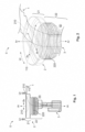
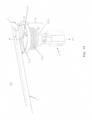
- the antenna device 0 with its flexible interconnect device 1 (c.f. Fig. 11 ) is mountable or mounted on/in a vehicle add-on part, in particular a motor vehicle add-on part, for example a spoiler or other add-on part.
- the vehicle add-on part is in turn mountable or mounted at/on/in a vehicle, wherein the flexible feedthrough portion 110 of the antenna interconnect device 1 is mountable or mounted in the feed-through 9 by means of the antenna sealing plug 2, wherein a portion of the antenna interconnect device 1 projects into the vehicle.
- the antenna interconnect device 1 - configured, for example, as a signal carrier, ribbon cable carrier, printed cable, sensor line etc. - preferably comprises a connector 3, for example for on-board electronics of the vehicle.
- the antenna sealing plug 2 (c.f. the drawing) comprises two mutually separate sealing portions or regions. - On the one hand, the antenna sealing plug 2 comprises a sealing surface 220 extending substantially all the way round in the circumferential direction Ur for sealing with respect to the feed-through 9 of the vehicle.
- the form of the circumference here is fundamentally arbitrary, although a substantially circular or elliptical form is, of course, preferred.
- the antenna sealing plug 2 comprises a slot-like passage 210.
- the flexible feedthrough portion 110 of the antenna interconnect device 1 can be guided or is guided through the antenna sealing plug 2 in a sealing manner via this slot-like passage 210. That is to say, when the feedthrough portion 110 is mounted in the slot-like passage 210, a liquid cannot pass from one axial side of the antenna sealing plug 2 to the other axial side of the antenna sealing plug 2 through the slot-like passage 210.
- the slot-like passage 210 here may be arranged in the antenna sealing plug 2 in a variety of ways; four of these embodiments are explained in more detail below. - In this regard, it is, for example, possible (c.f. Fig. 1 and 2 ) to configure the slot-like passage 210 as a channel which is completely closed in its circumferential direction, at least in certain longitudinal portions, and which has an expanded rectangular cross section (c.f. Fig. 2 ), for example.
- the slot-like passage 210 here comprises at least or precisely two openings in the antenna sealing plug 2, wherein the feedthrough portion 110, coming from one such opening, is moved through the slot-like passage 210 so as to be mounted.
- the antenna sealing plug 2 (c.f. Fig. 3 to 5 ) may furthermore be mainly or substantially formed in two parts.
- the slot-like passage 210 here can be arranged between these two parts of the antenna sealing plug 2, and is arranged between these two parts of the antenna sealing plug 2 when the feedthrough portion 110 has been mounted. To this end, the feedthrough portion 110 is placed in one of the two parts and the second part closes the first part so that the antenna sealing plug 2 is fully operational.
- the slot-like passage 210 which can be arranged between the two parts, may be suitable for only one circumferential position or a plurality of circumferential positions of the feedthrough portion 110 with respect to the antenna sealing plug 2.
- circumferential positions established between the two parts which can be provided once or multiple times with an offset of ca.: 30°, 45°, 60° or 90°. It is furthermore possible to provide a continuous region for circumferential positions of the feedthrough portion 110 of ca.: 45°, 60°, 90°, 135°, 150°, 180°, 225°, 270°, 315°, 360°, i.e. smaller than or up to 360°, in which the feedthrough portion 110 may be arranged between the two parts.
- the slot-like passage 210 of the antenna sealing plug 2 is, for example, furthermore possible (c.f. Fig. 6 ) to configure the slot-like passage 210 of the antenna sealing plug 2 as a laterally open slot-like channel.
- the slot-like channel here extends laterally into the antenna sealing plug 2 in the radial direction Rr and preferably completely through the antenna sealing plug 2 in the axial direction Ar.
- the slot-like passage 210 here comprises three openings in the antenna sealing plug 2, wherein the feedthrough portion 110, coming from one such opening, in particular the lateral opening, is moved into the antenna sealing plug 2 (lateral opening) or through the antenna sealing plug 2 (opening on an axial side).
- the antenna sealing plug 2 may already be mounted in the feed-through 9.
- the slot-like passage 210 which is arranged substantially linearly in the antenna sealing plug 2 in Fig. 6 , to not only be arranged linearly in the antenna sealing plug 2.
- C.f. Fig. 7 and 8 in which the slot-like passage 210 of Fig. 6 is arranged in the antenna sealing plug 2 as an undulating slot-like passage 210.
- the number of undulations here is arbitrary and, of course, starts with one.
- Other options for arranging a slot-like passage 210 in the antenna sealing plug 2 can, of course, be used according to the invention.
- a preferred form of the antenna sealing plug 2 (c.f. Fig. 1 to 8 ) is divided into at least two portions, a plug head 21 which is wider in the radial direction Rr and a plug body 22 which is narrower than the plug head in the radial direction Rr.
- the plug body 22 here preferably comprises, on the radial Rr outer side, the sealing surface 220 extending substantially all the way round in the circumferential direction Ur for sealing the feed-through 9.
- the sealing surface 220 may be arranged partially or substantially completely (not illustrated) over an entire axial Ar length on the outside of the plug body 22.
- the sealing surface 220 comprises integral sealing means, e.g. sealing lips, sealing ribs etc., extending, for example, substantially all the way round in the circumferential direction Ur.
- the slot-like passage 210 enters at/in the plug head 21 or at/in a transition portion (not illustrated) of the plug head 21 and the plug body 22 (at the top in each case in Fig. 1 to 6 and at the bottom in each case in Fig. 7 and 8 , with reference to the orientated plane of the drawing).
- the slot-like passage 210 may lead in or out substantially radially Rr (c.f. Fig. 1 to 5 ) or substantially axially Ar (c.f. Fig. 6 to 8 ) at/in the opening into the plug head 21.
- a combination of a radial Rr and axial Ar, i.e. an angled or inclined (not illustrated) lead-in or lead-out into/out of the plug head 21 can, of course, also apply.
- the slot-like passage 210 enters at/in the plug body 22 (at the bottom in each case in Fig. 1 to 6 and at the top in each case in Fig. 7 to 8 , with reference to the orientated plane of the drawing).
- the slot-like passage 210 here may lead in or out substantially axially Ar (c.f. the drawing) at/in the opening into the plug head 21.
- a combination of a radial Rr and axial Ar, i.e. an angled or inclined (not illustrated) lead-in or lead-out into/out of the plug body 22 can, of course, also apply.
- the slot-like passage 210 on/in the plug body 22 leads within a receptacle 223 for the connector 3 (c.f. Fig. 1, 2 and 7 to 10 ).
- the antenna sealing plug 2 may be conceived substantially as a single part (c.f. Fig. 1, 2 , 6 to 8 ) or substantially in two parts (c.f. Fig. 5 to 7 ).
- the antenna sealing plug 2 may be configured as an antenna sealing plug 2 in which a slot is made from the outside.
- a relevant slot which can be seen on the outside of the sealing plug 2, i.e. the slot-like passage 210, may show only radially Rr on the plug head 21 (c.f. Fig. 1 and 2 ) or on the transition portion of the plug head 21 and the plug body 22 (not illustrated), only axially Ar (c.f. Fig. 6 to 8 ) on the plug body 22, and possibly radially Rr on the plug body 22 (c.f. Fig. 6 to 8 , although it is not shown).
- the antenna sealing plug 2 may be constructed as an integral part (hinge 27, in particular film hinge 27, c.f. Fig. 3 to 5 ) or from two pieces (not illustrated).
- the antenna sealing plug 2 here (c.f. Fig. 3 to 5 ) may be divided into a plug cap 25; 25, 21 and a cup-like plug portion 26; 26, 21, 22.
- the plug cap 25 here may divide the plug head 21 into two axial Ar portions (dividing plane), wherein one portion of the plug head 21 forms the plug cap 25 and the other portion of the plug head 21, together with the plug body 22, forms the cup-like plug portion 26; 26, 21, 22.
- the integral hinge 27, in particular the integral film hinge 27, may, on the one hand, be arranged on the antenna sealing plug 2 on a radial Ra and/or axial Ar outer side of the plug cap 25 and on a radial Ra and/or axial Ar outer side of the cup-like plug portion 26.
- these may be configured with respect to one another in such a way that the plug cap 25 may be pushed onto/into the cup-like plug portion 26 in any circumferential position.
- the plug cap 25 and the cup-like plug portion 26 are furthermore preferably configured with respect to one another in such a way that the plug cap 25, when pushed onto/into the cup-like plug portion 26, ensures that the two parts automatically remain connected to one another. That is to say, for example, in the joined-together state of the plug cap 25 and the cup-like plug portion 26, the plug cap 25 latches on/in the cup-like plug portion 26 and/or the two may be otherwise connected to one another in a mutually fixed manner.
- the slot-like passage 210 in the antenna sealing plug 2 may begin or end on the radial Rr (c.f. Fig. 1 to 5 of the drawing) outer side or axial Ar (c.f. Fig. 6 to 8 of the drawing) outer side of the plug head 21.
- the slot-like passage 210 may end or begin on the axial Ar ( Fig. 1 to 8 ) outer side of the plug head 21, wherein the slot-like passage 210 may end or begin in the receptacle 223 for the connector 3.
- the slot-like passage 210 may fundamentally lead through the antenna sealing plug 2 in any desired manner.
- radii can be used to prevent the feedthrough portion 110 from kinking. It is therefore possible, for example, (c.f. Fig. 1 and 2 (analogously Fig. 3 to 5 )) to have the lead-through portion 110 enter the antenna sealing plug 2 radially Rr at top. Within the antenna sealing plug 2, the feedthrough portion 110 then bends increasingly in the axial direction Ar with a comparatively large or substantially maximum radius and exits the antenna sealing plug 2 substantially in the axial direction Ar.
- radii so that the slot-like passage 210 does not kink may also depend, in particular, on an environment of the feed-through 9.
- an embodiment according to Fig. 6 to 8 can therefore be advantageously used if the feedthrough portion 110 is coming from an axial direction Ar.
- An embodiment according to Fig. 1 to 5 can, for example, then be more advantageously used (as shown in Fig. 1 to 4 ) if the feedthrough portion 110 comes from a radial direction Rr.
- feedthrough portions 110 which may already be bent with small radii or already have such small radii (kinks).
- the plug body 22 may comprise, at its free axial Ar end portion, the receptacle 223 for the connector 3.
- the receptacle 223 here should preferably be configured in such a way that the connector 3 may be clamped in the receptacle 223. This may take place, for example, by configuring portions of the receptacle 223 in a form-fitting manner with respect to the connector 3. It is furthermore preferable for at least one internal dimension of the receptacle 223 to be smaller than a corresponding external dimension of the connector 3 so that the connector 3 may be clamped, in particular clamped in a form-fitting manner, in the receptacle 223 owing to the elastic material of the receptacle 223.
- the antenna sealing plug 2 which is pre-mounted on the feedthrough portion 110 and/or the antenna sealing plug 2 which has been mounted in the feed-through 9 during final assembly may furthermore comprise a securing means 290 (c.f above for examples), by means of which a mechanical contact pressure can be applied to the feedthrough portion 110. This is only shown in Fig. 8 , although it may apply to all embodiments of the invention.
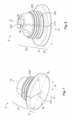
- Fig. 9 and 10 show an embodiment of the antenna sealing plug 2 (pre-mounting position) with an open slot-like passage 210.
- the feedthrough portion 110 may thus be arranged in the slot-like passage 210 and in the antenna sealing plug 2 in a simple and positionally accurate manner and the antenna sealing plug 2 may then be pre-mounted (for example with the securing means 290) or mounted (in the feed-through 9) in the final assembly.
- the open slot-like passage 210 extends, in particular, completely through the antenna sealing plug 2 in the axial direction Ar and, in particular, into the antenna sealing plug 2 in the radial direction Rr, wherein, in the pre-mounting position, the open slot-like passage 210 extends in the antenna sealing plug 2 such that it tapers in particular in the radial direction Rr. That is to say, the slot-like passage 210 opens outwards in the radial direction Rr.
- the open slot-like passage 210 has the approximate form of a triangle.
- the antenna sealing plug 2 may be configured with an open slot-like passage 210 as a rotationally symmetrical or only approximately rotationally symmetrical body; which may also apply to the other embodiments of the invention. If such an antenna sealing plug 2 is configured only as an approximately rotationally symmetrical body, it is preferably configured in such a way that it has a substantially rotationally symmetrical form when its slot-like passage 210 is closed.
- the open slot-like passage 210 is closed during mounting or pre-mounting of the antenna sealing plug 2. This closed position may be achieved and ensured by the securing means 290 and/or the feed-through 9.
- the open slot-like passage 210 can be combined, in particular, with the embodiments according to Fig. 6 to 8 .
- the antenna sealing plug 2 may furthermore have any desired form, so long as it may be arranged in the feed-through 9 such that the feedthrough portion 110 is sealed with respect to the sealing plug itself 2 and the sealing plug itself 2 is sealed.
- Fig. 9 and 10 furthermore each show an undulating slot-like passage 210.
- an undulation of the slot-like passage 210 is arranged within the antenna sealing plug 2 in at least one axial Ar outer (212) or inner (222) region of the antenna sealing plug 2 in such a way that the feedthrough portion 110 of the antenna interconnect device 1 can be guided or is guided in a desired direction.
- a passage portion 212, 222 of an outer or inner undulation (as seen in the axial direction) of the undulating slot-like passage 210 is arranged in the antenna sealing plug 2 in such a way that the passage portion 212, 222 allows the feedthrough portion 110 of the antenna sealing carrier 1 to face in the direction of an installation position.
- This can of course also be applied to slot-like passages 210 without undulations.
- a radius 212, 222, a progression 212, 222 or an end 212, 222 of an outer (212) and/or inner (222) undulation (passage portion 212, 222) located in the antenna sealing plug 2 or an outer and/or inner portion (passage portion 212, 222) for the feedthrough portion 110 in the antenna sealing plug 2 may be arranged in such a way that, on the one hand, the feedthrough portion 110 can be guided without deflections, for example with a large radius, or at a relatively small angle, with respect to the rest of the antenna interconnect device 1 (passage portion 212, c.f. Fig.
- Fig. 10 furthermore shows a coding 211 for the antenna sealing plug 2.
- the coding 211 here is configured as a coding 211 extending into the antenna sealing plug 2 in the radial direction Rr.
- a radial projection as a coding 211 can, of course, likewise be used.
- the coding 211 is arranged in/on the plug head 211; it may, of course, also be additionally or alternatively provided in/on the plug body 22, in/on the plug cap 25 and/or in/on the cup-like plug portion 26.
- the coding 211 may or may not be used in all embodiments of the invention.
Landscapes
- Engineering & Computer Science (AREA)
- Mechanical Engineering (AREA)
- Connector Housings Or Holding Contact Members (AREA)
- Fittings On The Vehicle Exterior For Carrying Loads, And Devices For Holding Or Mounting Articles (AREA)
- Support Of Aerials (AREA)
- Details Of Aerials (AREA)
Abstract
Description
- The invention relates to an antenna sealing plug for a flexible antenna interconnect device of an antenna device, for a vehicle, in particular a motor vehicle. The invention furthermore relates to an antenna device for a vehicle, in particular a motor vehicle; and a vehicle add-on part, in particular a motor vehicle add-on part, preferably a spoiler.
- Known antennas with flexible antenna interconnect devices, which may be used in a damp and/or wet region of a vehicle, in particular a motor vehicle, for example in a spoiler, are often sealed with respect to a feed-through, which guides the antenna interconnect device into the vehicle, by means of a hot melt adhesive. A problem with this is that, in many cases, the hot melt adhesive does not meet the increased temperature requirements on/in a vehicle, its sealing properties do not fully satisfy the product requirements and the processing time is long. A tool is furthermore required for supplying the hot melt adhesive.
-
CN 104 691 452 A discloses an installation device in a roof of a motor vehicle for an antenna feed, which guides the antenna feed into an interior of the motor vehicle and is intended to prevent water from penetrating into the motor vehicle. In this case, a hollow stud is mounted in the roof, in the outer end of which hollow stud a slot is arranged, through which the antenna feed is guided into the hollow stud and, from there, into the interior. A seal plug, through which the antenna feed is guided, is arranged in the hollow stud and is seated on an inner wall of the hollow stud in a sealing manner. A sealing material is furthermore provided in the outer portion of the hollow stud and a water-tight cap is mounted on the outside of the hollow stud. -
JP 2010-52499 A - The previous options for mounting an antenna device, for example in a spoiler on a vehicle, in particular a motor vehicle, do not always meet the vehicle requirements and the manufacturers' specifications. The conventional methods are furthermore time-consuming and costly. - An object of the invention, therefore, is to specify an improved antenna device and, on the basis of this, an improved vehicle add-on part, for example a spoiler.
- The object of the invention is achieved by means of an antenna sealing plug for a flexible antenna interconnect device of an antenna device, for a vehicle, in particular a motor vehicle; by means of an antenna device for a vehicle, in particular a motor vehicle; and by means of a vehicle add-on part, in particular a motor vehicle add-on part, preferably a spoiler. - Advantageous developments, additional features and/or advantages of the invention can be found in the dependent claims and the following description.
- The antenna sealing plug according to the invention comprises a sealing surface, extending substantially all the way round in the circumferential direction of the antenna sealing plug, for sealing a feed-through (through-recess, opening etc.) of the vehicle, which leads into the vehicle and through which a feedthrough portion of an antenna interconnect device may be guided or is guided, wherein the antenna sealing plug furthermore comprises a slot-like passage through which the feedthrough portion of the antenna interconnect device can be guided or is guided through the antenna sealing plug in a sealing manner. - Such a flexible antenna interconnect device comprises, for example, a flexible substrate as an interconnect device or antenna carrier, a flexible conductive circuit structure or antenna structure and a flexible, insulating cover layer. The antenna interconnect device may be configured in particular as a populated antenna interconnect device, or possibly also as an unpopulated antenna interconnect device.
- The antenna sealing plug is, in particular, not produced from a hot melt adhesive, but, for example, from a thermoplastic elastomer, terpolymer or synthetic rubber, whereby a material of the antenna sealing plug also meets increased requirements in terms of its environmental behaviour (temperature requirements, sealing properties etc.), durability and mechanical properties. This furthermore means that, for provision of the antenna sealing plug, i.e. for prefabricating an antenna device or mounting the antenna device, a production tool for the antenna sealing plug is not required. A sealing tool for processing the entire antenna in the final assembly phase is therefore not required. That is to say, rapid mounting may take place, wherein the antenna interconnect device (antenna foil) does not have to be placed in a tool.
- The antenna sealing plug may be configured in such a way that the slot-like passage leads in at/in a first outer region of the antenna sealing plug and leads out again at/in a second outer region of the antenna sealing plug. The antenna sealing plug may furthermore be configured in such a way that, at least in a mounting position of the antenna sealing plug, the slot-like passage is substantially completely surrounded by a material of the antenna sealing plug in its circumferential direction at at least one point along its path through the antenna sealing plug. The fact that the material of the antenna sealing plug extends completely around the feedthrough portion at at least one point guarantees a tightness of a region locally upstream of this point (for example outside the antenna sealing plug, for instance in a spoiler or another add-on part) with respect to a region locally downstream of this point (for example outside the antenna sealing plug, for instance in the vehicle).
- The sealing slot-like passage may itself be configured as a curved, linear and/or undulating slot-like passage. In a pre-mounting position, for example for prefabrication or final assembly, the slot-like passage may be configured as a slot-like passage which opens in the radial direction of the antenna sealing plug (c.f.
Fig. 9 and 10 ). The sealing slot-like passage may comprise, in an axial portion, at least one passage portion (radius, progression, end) in the installation direction for the feedthrough portion. Such an embodiment may be combined with a coding (c.f. below) of the antenna sealing plug and/or a linear or undulating slot-like passage; this may, of course, also be combined with other embodiments. - A longitudinal portion of the sealing slot-like passage may be completely closed in its circumferential direction (c.f.
Fig. 1 and 2 ), open on one side (c.f.Fig. 6 to 8 ) or open on two sides (c.f.Fig. 3 to 5 ). If the slot-like passage is open in the circumferential direction, when the feedthrough portion has been inserted into the slot-like passage and the antenna sealing plug has been mounted, the slot-like passage is closed in the circumferential direction in such a way that it is liquid-tight or substantially liquid-tight. - A cross section of the sealing slot-like passage may, or may not, be adapted to a cross section of the feedthrough portion. In the first case, analogously to an expanded rectangular cross section of the feedthrough portion, for example, the cross section of the slot-like passage has an analogous cross section, for example. In the second case, the slot-like passage is merely constituted by two substantially parallel surfaces, for example.
- The sealing slot-like passage may extend completely through the antenna sealing plug (c.f. for example
Fig. 1, 2 ,5 to 8 ). A centre line of the slot-like passage extending completely through the antenna sealing plug may furthermore extend through the antenna sealing plug in the radial direction and/or in the axial direction of the antenna sealing plug. The sealing slot-like passage may extend completely through the antenna sealing plug (c.f. for exampleFig. 6 to 8 ). Moreover, a centre line of the slot-like passage extending part way into the antenna sealing plug may extend into the antenna sealing plug substantially in the radial direction of the antenna sealing plug. - A surface which is spanned by the slot-like passage in the antenna sealing plug may extend within the antenna sealing plug in the radial direction and axial direction of the antenna sealing plug (c.f. for example
Fig. 1, 2 and5 ). This surface may be constituted as a curved surface within the antenna sealing plug, with a linear section as a generatrix. That is to say, the surface spanned by the slot-like passage is configured as a developable surface. This surface may furthermore extend within the antenna sealing plug at least partially in the circumferential direction of the antenna sealing plug. That is to say, the surface spanned by the slot-like passage is configured as a circumferential portion of a funnel or of a cone portion or as a funnel or a cone portion. - A curved surface which is spanned by the sealing slot-like passage in the antenna sealing plug may begin or end on the radial outer side of the antenna sealing plug, progress substantially in a radial direction in a radial outer region in the antenna sealing plug, bend increasingly within the antenna sealing plug in the axial direction of the antenna sealing plug, progress substantially in the axial direction in an axial outer region in the antenna sealing plug, and/or end or begin on the axial outer side of the antenna sealing plug.
- A surface which is spanned by the slot-like passage in the antenna sealing plug may extend into the antenna sealing plug from an axial outer position on the antenna sealing plug. The surface here may extend in the axial direction in the antenna sealing plug as a substantially planar or undulating surface. Furthermore, a linear section as a generatrix of the surface here may extend into the antenna sealing plug substantially only in the radial direction of the antenna sealing plug (c.f. for example
Fig. 6 to 8 ). The surface may furthermore reach as far as a centre axis of the antenna sealing plug or intersect this centre axis. That is to say, in the latter case, the surface extends into the antenna sealing plug beyond the centre axis. The surface may moreover also "pass by" the centre axis. - The antenna sealing plug may be composed of two mutually connectable or connected portions. The two portions here are separated from one another or can be separated from one another by a plane which extends substantially exclusively in the radial directions of the antenna sealing plug (c.f.
Fig. 3 to 5 ). Alternatively, the two portions may be separated from one another by a possibly curved, for example undulating, half plane, which starts inside the antenna sealing plug and extends in the radial direction and/or in the axial direction of the antenna sealing plug (c.f.Fig. 6 to 8 ). The two portions may be configured to complement one another, at least in part, and/or be joined together in a form-fitting manner, at least in part (c.f.Fig. 3 to 8 ). - The antenna sealing plug may substantially be composed of two portions, a plug head and a plug body adjoining the plug head. The plug body here may comprise the substantially completely circumferential sealing surface for sealing the feed-through. The plug head, or a transition portion from the plug body into the plug head, may furthermore comprise an end portion of the slot-like passage for the feedthrough portion. The slot-like passage may furthermore extend into the plug body, starting from the plug head, and through the two.
- The antenna sealing plug may comprise two mutually connectable parts, a plug cap and a cup-like plug portion. A dividing plane of the antenna sealing plug here may be located in the plug head, which dividing plane divides the antenna sealing plug into the plug cap and the cup-like plug portion. The plug cap and the cup-like plug portion may be conceived as two mutually separate components and produced separately from one another. The plug cap and the cup-like plug portion may furthermore be conceived as a single part and produced together. The plug cap and the cup-like plug portion may be connected to one another via a hinge, in particular a film hinge.
- The antenna sealing plug or the plug body may comprise a receptacle for a connector. The connector may be, in particular, that of the flexible antenna interconnect device. The antenna interconnect device here may comprise electrical terminals, in particular terminals which are crimped thereto and which are received in the connector. The receptacle of the antenna sealing plug may be configured to complement the connector, at least in part. The connector may be insertable or inserted or placeable or placed into the receptacle in a form-fitting manner, at least in part. At least one internal dimension of the receptacle here is smaller than a corresponding external dimension of the connector. As a result of the elastic material of the antenna sealing plug, the connector may be received in the receptacle in a simple, clamped manner. Depending on the requirements for receiving the connector in the antenna sealing plug, the material of this latter (in terms of its hardness and/or other properties) may be adapted to a property of the connector and/or a subsequent property on the component and/or vehicle. A unit comprising the antenna sealing plug with the antenna interconnect device and the connector may be sealed directly here and produce an electrical connection in the intended component or vehicle.
- The antenna sealing plug is preferably configured as a moulded part, for example in an injection moulding procedure. That is to say, the antenna sealing plug is produced before being mounted on a feedthrough portion of an antenna interconnect device (prefabrication) and, of course, before being mounted in the feed-through (final assembly) of the vehicle. Therefore, it does not have to be produced during the prefabrication of an antenna device or mounting of the antenna device. Therefore, in a normal procedure, if something goes wrong following the injection moulding process, the interconnect device as a whole is not defective; that is to say, the handling is improved.
- On the one hand, it is possible to assemble the antenna device just before it is mounted in the intended component. On the other hand, it is possible to deliver the antenna device, fully pre-mounted, to the customer, to the assembly line or for mounting, so that it only needs to be installed. In the case of a repair, in the worst case scenario, it is only necessary to replace the sealing plug, and not the entire antenna interconnect device. Recycling (disconnecting or dismantling the antenna device again for reuse or further use) is furthermore facilitated. All in all, costs are significantly reduced because processes are omitted and the sealing with hot melt adhesive is omitted.
- Furthermore, the antenna sealing plug preferably has an integral configuration. An integral configuration is understood to mean a configuration of the antenna sealing plug in which there is only one single component, which cannot be divided without being destroyed. The antenna sealing plug is manufactured from a single initial mass (plastic melt), which, for the antenna sealing plug, must itself be integral. Such a fully functional antenna sealing plug is merely held together by adhesion and/or cohesion. The antenna sealing plug may furthermore be configured in one part or multiple parts, in particular in two parts.
- The antenna sealing plug furthermore preferably does not comprise hot melt adhesive. The antenna sealing plug is produced in particular from an elastic material, preferably an elastomer. The antenna sealing plug, in its pre-mounting position on the flexible antenna interconnect device or the feedthrough portion thereof, may comprise a securing means, by means of which a mechanical contact pressure can be applied to the antenna interconnect device or the feedthrough portion thereof. Such a securing means may be formed, for example, as a securing ring, a snap ring, an O ring, a clamp, a (spring) clip, etc. A mounted securing means here is preferably mounted on the outside of the antenna sealing plug and extends around the outside of the antenna sealing plug, preferably at least over part of its circumference, in particular as an O ring.
- The material of the antenna sealing plug may be selected, for example, according to production specifications and/or subsequent requirements in terms of its hardness, flexibility, (permanent) elasticity, environmental requirements and/or temperature conditions, amongst other things. The antenna sealing plug here may be adapted to the requirements of the intended component. An interconnect device and/or signal carrier (ribbon conductor, printed cable, sensor line) may be arranged within the feedthrough portion, wherein an HBL with a flat ribbon cable is one possible application. - The antenna sealing plug is provided, pre-fastened, on the antenna interconnect device for rapid and easier mounting, wherein, apart from mounting the antenna sealing plug, additional sealing work is not required.
- A strain-relief device, positioning aid and/or fastening means may be integrated in the antenna interconnect device or a foil of the antenna interconnect device; this facilitates the mounting of the antenna interconnect device in the antenna sealing plug and/or ensures the position of the antenna interconnect device on/in the antenna sealing plug. The strain-relief device, positioning aid and/or fastening means may be provided or arranged in the feedthrough portion and/or in/on the feedthrough portion so as to be adjacent, in particular immediately adjacent, to the antenna sealing plug. This may be realized, for example, by means of at least one projection at the top of the antenna interconnect device in the axial direction and at the bottom of the antenna interconnect device in the axial direction in each case. The projections receive the antenna sealing plug between them, for example. The antenna device according to the invention comprises an antenna interconnect device and an antenna sealing plug, wherein the antenna sealing plug is configured according to the invention. The antenna sealing plug may be pre-mounted on a feedthrough portion of the antenna interconnect device. The feedthrough portion, and therefore the antenna interconnect device, may furthermore extend completely through the antenna sealing plug. The feedthrough portion may furthermore be arranged in the antenna sealing plug such that it is substantially or completely liquid-tight. That is to say, there is a region of the antenna sealing plug which extends substantially completely around the feedthrough portion and which remains substantially dry in the event of liquid acting on the antenna sealing plug as a whole.
- The vehicle add-on part according to the invention, in particular the motor vehicle add-on part according to the invention, preferably the spoiler, comprises an antenna sealing plug and/or an antenna device, wherein the antenna sealing plug and/or the antenna device is or are configured according to the invention. A vehicle is understood to be a motor vehicle (road vehicle), a rail vehicle, a water vehicle or an aircraft. The motor vehicle here may comprise an internal combustion engine and/or an electric traction engine.
- The invention is explained in greater detail below on the basis of exemplary embodiments with reference to the appended drawing which is diagrammatic and not to scale. Portions, elements, component parts, units, components and/or patterns which have an identical, unique or analogous configuration and/or function are identified by the same reference signs in the description of the figures (see below), the list of reference signs, the patent claims and in the figures (Figs) of the drawing. A possible alternative which is not explained in the description of the invention (see above), is not shown in the drawing and/or is not definitive, a static and/or kinematic reversal, a combination etc. with respect to the exemplary embodiments of the invention or a component, a pattern, a unit, a component part, an element or a portion thereof, can further be gathered from the list of reference signs and/or the description of the figures.
- In the case of the invention, a feature (portion, element, component part, unit, component, function, variable etc.) can be of positive configuration, that is to say present, or of negative configuration, that is to say absent. In this specification (description (description of the invention (see above), description of the figures (see below)), list of reference signs, patent claims, drawing), a negative feature is not explained explicitly as a feature if value is not placed on it being absent according to the invention. That is to say, the invention which is actually created, and not one constructed by the prior art, consists in omitting the said feature.
- A feature of this specification can be utilized not only in a specified manner and/or way, but rather also in another manner and/or way (isolation, combination, replacement, addition, on its own, omission, etc.). It is possible, in particular, in the description, the list of reference signs, the patent claims and/or the drawing, to replace, add or omit a feature in the patent claims and/or the description on the basis of a reference sign and a feature which is assigned to it, or vice versa. Furthermore, a feature in a patent claim can be interpreted and/or specified in greater detail as a result.
- The features of the description can also be interpreted as optional features (in view of the (initially mostly unknown) prior art); that is to say, each feature can be considered to be an optional, arbitrary or preferred feature, that is to say a feature which is not mandatory. Therefore, a separation of a feature, possibly including its periphery, from an exemplary embodiment is possible, it then being possible for the said feature to be transferred to a generalized inventive concept. The absence of a feature (negative feature) in an exemplary embodiment shows that the feature is optional in relation to the invention. Furthermore, in the case of a type term for a feature, a generic term for the feature can also be implicitly understood (possibly further hierarchical breakdown into subgenus, etc.), as a result of which a generalization of the feature is possible, for example with consideration of equivalent effect and/or equivalence.
- In the merely exemplary figures (Figs):
-
Fig. 1 and 2 show, in a two-dimensional side view (Fig. 1 ) and a perspective view (Fig. 2 ), a first embodiment of an antenna sealing plug according to the invention for a flexible antenna interconnect device, -
Fig. 3 to 5 show, in three two-dimensional side views, a second embodiment of the antenna sealing plug according to the invention in a closed (Fig. 3 and 4 , incl. the flexible antenna interconnect device) and an open state (Fig. 5 ), -
Fig. 6 shows, in a perspective view, a third embodiment of the antenna sealing plug according to the invention for a flexible feedthrough portion of the antenna interconnect device, -
Fig. 7 and 8 show, in perspective views, a fourth embodiment of the antenna sealing plug according to the invention, -
Fig. 9 and 10 show, in a two-dimensional side view (Fig. 9 ) and a plan view (Fig. 10 ), a fifth embodiment of an antenna sealing plug according to the invention, and -
Fig. 11 shows, in a perspective view, an antenna sealing plug according to the invention according to the third, fourth or fifth embodiment, wherein a region of the antenna interconnect device of an antenna device is shown. - The invention is explained in more detail below with reference to exemplary embodiments of five embodiments (
Fig. 1 and 2 ,Fig. 3 to 5 ,Fig. 6 ,Fig. 7 and 8 ,Fig. 9 and 10 ) of a variant of an elasticantenna sealing plug 2 for aflexible feedthrough portion 110 of a substantially flexible antenna interconnect device 1 (Fig. 11 ) for anantenna device 0 for a vehicle, in particular a motor vehicle. Theantenna interconnect device 1 comprises, in particular, an actual transmitter antenna and/or receiver antenna and is preferably configured as anantenna interconnect device 1 with a flat extent. The flexible and, itself, preferablyflat feedthrough portion 110 here should be mountable and mounted in a feed-through 9 of the vehicle which leads into the vehicle. Theantenna sealing plug 2 here should or must seal the feed-through 9 with respect to a liquid on the one hand and should or must seal thefeedthrough portion 110 with respect to a liquid on the other. - The
antenna device 0 with its flexible interconnect device 1 (c.f.Fig. 11 ) is mountable or mounted on/in a vehicle add-on part, in particular a motor vehicle add-on part, for example a spoiler or other add-on part. The vehicle add-on part is in turn mountable or mounted at/on/in a vehicle, wherein theflexible feedthrough portion 110 of theantenna interconnect device 1 is mountable or mounted in the feed-through 9 by means of theantenna sealing plug 2, wherein a portion of theantenna interconnect device 1 projects into the vehicle. In this case, the antenna interconnect device 1 - configured, for example, as a signal carrier, ribbon cable carrier, printed cable, sensor line etc. - preferably comprises aconnector 3, for example for on-board electronics of the vehicle. - Although the invention is described and illustrated further in greater detail by way of preferred exemplary embodiments, the invention is not restricted by way of the disclosed exemplary embodiments, but rather is of more fundamental nature. Other variations can be derived therefrom and/or from the above (description of the invention), without departing from the scope of protection of the invention. The explanation of the invention with reference to the drawing furthermore relates hereinafter to an axial direction Ar or a centre axis Ar, a radial direction Rr and a circumferential direction Ur of the
antenna sealing plug 2. The invention can be generally used in the field of vehicle antennas, in particular in external or integrated roof antenna modules for motor vehicles. The drawing shows only those spatial portions of the subject matter of the invention which are necessary for understanding the invention. - The antenna sealing plug 2 (c.f. the drawing) comprises two mutually separate sealing portions or regions. - On the one hand, the
antenna sealing plug 2 comprises a sealingsurface 220 extending substantially all the way round in the circumferential direction Ur for sealing with respect to the feed-through 9 of the vehicle. The form of the circumference here is fundamentally arbitrary, although a substantially circular or elliptical form is, of course, preferred. - On the other hand, the
antenna sealing plug 2 comprises a slot-like passage 210. Theflexible feedthrough portion 110 of theantenna interconnect device 1 can be guided or is guided through theantenna sealing plug 2 in a sealing manner via this slot-like passage 210. That is to say, when thefeedthrough portion 110 is mounted in the slot-like passage 210, a liquid cannot pass from one axial side of theantenna sealing plug 2 to the other axial side of theantenna sealing plug 2 through the slot-like passage 210. - The slot-
like passage 210 here may be arranged in theantenna sealing plug 2 in a variety of ways; four of these embodiments are explained in more detail below. - In this regard, it is, for example, possible (c.f.Fig. 1 and 2 ) to configure the slot-like passage 210 as a channel which is completely closed in its circumferential direction, at least in certain longitudinal portions, and which has an expanded rectangular cross section (c.f.Fig. 2 ), for example. The slot-like passage 210 here comprises at least or precisely two openings in theantenna sealing plug 2, wherein thefeedthrough portion 110, coming from one such opening, is moved through the slot-like passage 210 so as to be mounted. - The antenna sealing plug 2 (c.f.
Fig. 3 to 5 ) may furthermore be mainly or substantially formed in two parts. The slot-like passage 210 here can be arranged between these two parts of theantenna sealing plug 2, and is arranged between these two parts of theantenna sealing plug 2 when thefeedthrough portion 110 has been mounted. To this end, thefeedthrough portion 110 is placed in one of the two parts and the second part closes the first part so that theantenna sealing plug 2 is fully operational. - The slot-
like passage 210, which can be arranged between the two parts, may be suitable for only one circumferential position or a plurality of circumferential positions of thefeedthrough portion 110 with respect to theantenna sealing plug 2. For example, circumferential positions established between the two parts, which can be provided once or multiple times with an offset of ca.: 30°, 45°, 60° or 90°. It is furthermore possible to provide a continuous region for circumferential positions of thefeedthrough portion 110 of ca.: 45°, 60°, 90°, 135°, 150°, 180°, 225°, 270°, 315°, 360°, i.e. smaller than or up to 360°, in which thefeedthrough portion 110 may be arranged between the two parts. - It is, for example, furthermore possible (c.f.
Fig. 6 ) to configure the slot-like passage 210 of theantenna sealing plug 2 as a laterally open slot-like channel. The slot-like channel here extends laterally into theantenna sealing plug 2 in the radial direction Rr and preferably completely through theantenna sealing plug 2 in the axial direction Ar. The slot-like passage 210 here comprises three openings in theantenna sealing plug 2, wherein thefeedthrough portion 110, coming from one such opening, in particular the lateral opening, is moved into the antenna sealing plug 2 (lateral opening) or through the antenna sealing plug 2 (opening on an axial side). In the latter exemplary embodiment, theantenna sealing plug 2 may already be mounted in the feed-through 9. - Moreover, it is possible for the slot-
like passage 210, which is arranged substantially linearly in theantenna sealing plug 2 inFig. 6 , to not only be arranged linearly in theantenna sealing plug 2. C.f.Fig. 7 and 8 , in which the slot-like passage 210 ofFig. 6 is arranged in theantenna sealing plug 2 as an undulating slot-like passage 210. The number of undulations here is arbitrary and, of course, starts with one. - Other options for arranging a slot-like passage 210 in theantenna sealing plug 2 can, of course, be used according to the invention. - A preferred form of the antenna sealing plug 2 (c.f.
Fig. 1 to 8 ) is divided into at least two portions, aplug head 21 which is wider in the radial direction Rr and aplug body 22 which is narrower than the plug head in the radial direction Rr. This gives the antenna sealing plug 2 a mushroom-like appearance with a preferablyflat plug head 21, in which the outer diameters are preferably constant in the axial direction Ar, and a preferably somewhat narrower, and instead taller, plugbody 22, in which the outer diameters are preferably substantially constant in the axial direction Ar, at least in certain portions (sealing means). Theplug body 22 here preferably comprises, on the radial Rr outer side, the sealingsurface 220 extending substantially all the way round in the circumferential direction Ur for sealing the feed-through 9. The sealingsurface 220 may be arranged partially or substantially completely (not illustrated) over an entire axial Ar length on the outside of theplug body 22. The sealingsurface 220 comprises integral sealing means, e.g. sealing lips, sealing ribs etc., extending, for example, substantially all the way round in the circumferential direction Ur. - On the one hand, the slot-
like passage 210 enters at/in theplug head 21 or at/in a transition portion (not illustrated) of theplug head 21 and the plug body 22 (at the top in each case inFig. 1 to 6 and at the bottom in each case inFig. 7 and 8 , with reference to the orientated plane of the drawing). The slot-like passage 210 may lead in or out substantially radially Rr (c.f.Fig. 1 to 5 ) or substantially axially Ar (c.f.Fig. 6 to 8 ) at/in the opening into theplug head 21. A combination of a radial Rr and axial Ar, i.e. an angled or inclined (not illustrated) lead-in or lead-out into/out of theplug head 21 can, of course, also apply. - On the other hand, the slot-
like passage 210 enters at/in the plug body 22 (at the bottom in each case inFig. 1 to 6 and at the top in each case inFig. 7 to 8 , with reference to the orientated plane of the drawing). The slot-like passage 210 here may lead in or out substantially axially Ar (c.f. the drawing) at/in the opening into theplug head 21. A combination of a radial Rr and axial Ar, i.e. an angled or inclined (not illustrated) lead-in or lead-out into/out of theplug body 22 can, of course, also apply. In particular, the slot-like passage 210 on/in theplug body 22 leads within areceptacle 223 for the connector 3 (c.f.Fig. 1, 2 and7 to 10 ). - The
antenna sealing plug 2 may be conceived substantially as a single part (c.f.Fig. 1, 2 ,6 to 8 ) or substantially in two parts (c.f.Fig. 5 to 7 ). - In the case of the single-part, integral configuration, theantenna sealing plug 2 may be configured as anantenna sealing plug 2 in which a slot is made from the outside. A relevant slot which can be seen on the outside of the sealingplug 2, i.e. the slot-like passage 210, may show only radially Rr on the plug head 21 (c.f.Fig. 1 and 2 ) or on the transition portion of theplug head 21 and the plug body 22 (not illustrated), only axially Ar (c.f.Fig. 6 to 8 ) on theplug body 22, and possibly radially Rr on the plug body 22 (c.f.Fig. 6 to 8 , although it is not shown). - In the case of the two-part configuration, the
antenna sealing plug 2 may be constructed as an integral part (hinge 27, inparticular film hinge 27, c.f.Fig. 3 to 5 ) or from two pieces (not illustrated). Theantenna sealing plug 2 here (c.f.Fig. 3 to 5 ) may be divided into a plug cap 25; 25, 21 and a cup-like plug portion 26; 26, 21, 22. The plug cap 25 here may divide theplug head 21 into two axial Ar portions (dividing plane), wherein one portion of theplug head 21 forms the plug cap 25 and the other portion of theplug head 21, together with theplug body 22, forms the cup-like plug portion 26; 26, 21, 22. - In the case of the integral configuration of the plug cap 25 and cup-like plug portion 26 (c.f.
Fig. 3 to 5 ), theintegral hinge 27, in particular theintegral film hinge 27, may, on the one hand, be arranged on theantenna sealing plug 2 on a radial Ra and/or axial Ar outer side of the plug cap 25 and on a radial Ra and/or axial Ar outer side of the cup-like plug portion 26. In the case of the two-piece configuration of the plug cap 25 and cup-like plug portion 26, these may be configured with respect to one another in such a way that the plug cap 25 may be pushed onto/into the cup-like plug portion 26 in any circumferential position. - The plug cap 25 and the cup-like plug portion 26 are furthermore preferably configured with respect to one another in such a way that the plug cap 25, when pushed onto/into the cup-like plug portion 26, ensures that the two parts automatically remain connected to one another. That is to say, for example, in the joined-together state of the plug cap 25 and the cup-like plug portion 26, the plug cap 25 latches on/in the cup-like plug portion 26 and/or the two may be otherwise connected to one another in a mutually fixed manner.
- The slot-
like passage 210 in theantenna sealing plug 2 may begin or end on the radial Rr (c.f.Fig. 1 to 5 of the drawing) outer side or axial Ar (c.f.Fig. 6 to 8 of the drawing) outer side of theplug head 21. Analogously, the slot-like passage 210 may end or begin on the axial Ar (Fig. 1 to 8 ) outer side of theplug head 21, wherein the slot-like passage 210 may end or begin in thereceptacle 223 for theconnector 3. Between a beginning and end or an end and beginning of the slot-like passage 210 in theantenna sealing plug 2, the slot-like passage 210 may fundamentally lead through theantenna sealing plug 2 in any desired manner. - In particular, at the entry, in the passage and at the exit for the
feedthrough portion 110 into/through/from theantenna sealing plug 2, radii can be used to prevent thefeedthrough portion 110 from kinking. It is therefore possible, for example, (c.f.Fig. 1 and 2 (analogouslyFig. 3 to 5 )) to have the lead-throughportion 110 enter theantenna sealing plug 2 radially Rr at top. Within theantenna sealing plug 2, thefeedthrough portion 110 then bends increasingly in the axial direction Ar with a comparatively large or substantially maximum radius and exits theantenna sealing plug 2 substantially in the axial direction Ar. - The use of radii so that the slot-
like passage 210 does not kink may also depend, in particular, on an environment of the feed-through 9. For example, an embodiment according toFig. 6 to 8 can therefore be advantageously used if thefeedthrough portion 110 is coming from an axial direction Ar. An embodiment according toFig. 1 to 5 can, for example, then be more advantageously used (as shown inFig. 1 to 4 ) if thefeedthrough portion 110 comes from a radial direction Rr. Exceptions here are, of course,feedthrough portions 110 which may already be bent with small radii or already have such small radii (kinks). - The
plug body 22 may comprise, at its free axial Ar end portion, thereceptacle 223 for theconnector 3. Thereceptacle 223 here should preferably be configured in such a way that theconnector 3 may be clamped in thereceptacle 223. This may take place, for example, by configuring portions of thereceptacle 223 in a form-fitting manner with respect to theconnector 3. It is furthermore preferable for at least one internal dimension of thereceptacle 223 to be smaller than a corresponding external dimension of theconnector 3 so that theconnector 3 may be clamped, in particular clamped in a form-fitting manner, in thereceptacle 223 owing to the elastic material of thereceptacle 223. - The
antenna sealing plug 2 which is pre-mounted on thefeedthrough portion 110 and/or theantenna sealing plug 2 which has been mounted in the feed-through 9 during final assembly may furthermore comprise a securing means 290 (c.f above for examples), by means of which a mechanical contact pressure can be applied to thefeedthrough portion 110. This is only shown inFig. 8 , although it may apply to all embodiments of the invention. -
Fig. 9 and 10 show an embodiment of the antenna sealing plug 2 (pre-mounting position) with an open slot-like passage 210. Thefeedthrough portion 110 may thus be arranged in the slot-like passage 210 and in theantenna sealing plug 2 in a simple and positionally accurate manner and theantenna sealing plug 2 may then be pre-mounted (for example with the securing means 290) or mounted (in the feed-through 9) in the final assembly. - The open slot-
like passage 210 extends, in particular, completely through theantenna sealing plug 2 in the axial direction Ar and, in particular, into theantenna sealing plug 2 in the radial direction Rr, wherein, in the pre-mounting position, the open slot-like passage 210 extends in theantenna sealing plug 2 such that it tapers in particular in the radial direction Rr. That is to say, the slot-like passage 210 opens outwards in the radial direction Rr. In a plan view of theantenna sealing plug 2, the open slot-like passage 210 has the approximate form of a triangle. - None (not illustrated), at least one (represented approximately in
Fig. 10 ) or both inner flanks (not illustrated) of the open slot-like passage 210 may be aligned in the direction of the centre of the slot-like passage 210, reach the centre of the slot-like passage or extend beyond the centre of the slot-like passage (c.f.Fig. 10 ). In a specific form for its function, theantenna sealing plug 2 may be configured with an open slot-like passage 210 as a rotationally symmetrical or only approximately rotationally symmetrical body; which may also apply to the other embodiments of the invention. If such anantenna sealing plug 2 is configured only as an approximately rotationally symmetrical body, it is preferably configured in such a way that it has a substantially rotationally symmetrical form when its slot-like passage 210 is closed. - The open slot-
like passage 210 is closed during mounting or pre-mounting of theantenna sealing plug 2. This closed position may be achieved and ensured by the securing means 290 and/or the feed-through 9. The open slot-like passage 210 can be combined, in particular, with the embodiments according toFig. 6 to 8 . Theantenna sealing plug 2 may furthermore have any desired form, so long as it may be arranged in the feed-through 9 such that thefeedthrough portion 110 is sealed with respect to the sealing plug itself 2 and the sealing plug itself 2 is sealed. -
Fig. 9 and 10 furthermore each show an undulating slot-like passage 210. It is preferred here that an undulation of the slot-like passage 210 is arranged within theantenna sealing plug 2 in at least one axial Ar outer (212) or inner (222) region of theantenna sealing plug 2 in such a way that thefeedthrough portion 110 of theantenna interconnect device 1 can be guided or is guided in a desired direction. That is to say, apassage portion like passage 210 is arranged in theantenna sealing plug 2 in such a way that thepassage portion feedthrough portion 110 of theantenna sealing carrier 1 to face in the direction of an installation position. -This can of course also be applied to slot-like passages 210 without undulations. - For example, a
radius progression end passage portion 212, 222) located in theantenna sealing plug 2 or an outer and/or inner portion (passage portion 212, 222) for thefeedthrough portion 110 in theantenna sealing plug 2 may be arranged in such a way that, on the one hand, thefeedthrough portion 110 can be guided without deflections, for example with a large radius, or at a relatively small angle, with respect to the rest of the antenna interconnect device 1 (passage portion 212, c.f.Fig. 11 ), and/or, on the other hand, can be guided without deflections, for example with a comparatively large radius, to theconnector 3 in the antenna sealing plug 2 (c.f.Fig. 9 ), another connector (not illustrated) or a connection in the vehicle (not illustrated). -
Fig. 10 furthermore shows acoding 211 for theantenna sealing plug 2. Thecoding 211 here is configured as acoding 211 extending into theantenna sealing plug 2 in the radial direction Rr. A radial projection as acoding 211 can, of course, likewise be used. In the present case, thecoding 211 is arranged in/on theplug head 211; it may, of course, also be additionally or alternatively provided in/on theplug body 22, in/on the plug cap 25 and/or in/on the cup-like plug portion 26. Thecoding 211 may or may not be used in all embodiments of the invention. -
- 0
- Antenna device for a vehicle, in particular a motor vehicle
- 1
- (Flexible) antenna interconnect device of the
antenna device 0 - 2
- (Elastic) antenna sealing plug for the
antenna interconnect device 1 - 3
- Connector of the
antenna interconnect device 1 - 9
- Feed-through (leading into the vehicle)
- 110
- (Flexible) feedthrough portion of the
antenna interconnect device 1 - 21
- Plug head
- 22
- Plug body
- 25
- Plug cap
- 26
- Cup-like plug portion
- 27
- Hinge, in particular film hinge
- 210
- (Sealing) slot-like passage
- 211
- Coding
- 212
- Passage portion in the direction of the installation position
- 220
- (Substantially completely circumferential) sealing surface
- 222
- Passage portion in the direction of the insertion position
- 223
- Receptacle for
connector 3 - 290
- Securing means
- Ar
- Axial direction, centre axis of the
antenna sealing plug 2 - Rr
- Radial direction of the
antenna sealing plug 2 - Ur
- Circumferential direction of the
antenna sealing plug 2
Claims (15)
- Antenna sealing plug (2) for a flexible antenna interconnect device (1) of an antenna device (0) for a vehicle, in particular a motor vehicle, havinga sealing surface (220) extending substantially all the way round in the circumferential direction (Ur) of the antenna sealing plug (2) for sealing a feed-through (9) of the vehicle, which leads into the vehicle and through which a feedthrough portion (110) of the antenna interconnect device (1) can be guided or is guided, characterized in thatthe antenna sealing plug (2) furthermore comprises a slot-like passage (210), through which the feedthrough portion (110) of the antenna interconnect device (1) can be guided or is guided through the antenna sealing plug (2) in a sealing manner.
- Antenna sealing plug (2) according to the preceding claim, characterized in that the antenna sealing plug (2) is configured in such a way that the slot-like passage (210)leads in at/in a first outer region of the antenna sealing plug (2), and leads out again at/in a second outer region of the antenna sealing plug (2), and/or,at least in a mounting position of the antenna sealing plug (2), is substantially completely surrounded by a material of the antenna sealing plug (2) in its circumferential direction at at least at one point along its path through the antenna sealing plug (2).
- Antenna sealing plug (2) according to any one of the preceding claims, characterized in that:□ the sealing slot-like passage itself (210) may be configured as a curved, linear and/or undulating slot-like passage (210),□ in a pre-mounting position, the slot-like passage (210) is configured as a slot-like passage (210) which opens in the radial direction (Rr) of the antenna sealing plug (2),□ a longitudinal portion of the sealing slot-like passage (210) is completely closed in the circumferential direction, open on one side or open on two sides, and/or□ the sealing slot-like passage (210) comprises, in an axial (Ar) portion, at least one passage portion (212, 222) in the installation direction for the feedthrough portion (110).
- Antenna sealing plug (2) according to any one of the preceding claims, characterized in that:□ the sealing slot-like passage (210) extends completely through the antenna sealing plug (2),□ a centre line of the slot-like passage (210) extending completely through the antenna sealing plug (2) extends through the antenna sealing plug (2) in the radial direction (Rr) and/or in the axial direction (Ar) of the antenna sealing plug (2)□ the sealing slot-like passage (210) extends part way into the antenna sealing plug (2), and/or□ a centre line of the slot-like passage (210) extending part way into the antenna sealing plug (2) extends into the antenna sealing plug (2) substantially in the radial direction (Rr) of the antenna sealing plug (2).
- Antenna sealing plug (2) according to any one of the preceding claims, characterized in that a surface which is spanned by the slot-like passage (210) in the antenna sealing plug (2)□ extends within the antenna sealing plug (2) in the radial direction (Rr) and axial direction (Ar) of the antenna sealing plug (2),□ is constituted as a curved surface within the antenna sealing plug (2), with a linear section as a generatrix,□ extends within the antenna sealing plug (2) at least partially in the circumferential direction (Ur) of the antenna sealing plug (2).
- Antenna sealing plug (2) according to any one of the preceding claims, characterized in that a curved surface which is spanned by the sealing slot-like passage (210) in the antenna sealing plug (2):□ begins or ends on the radial (Rr) outer side of the antenna sealing plug (2),□ progresses substantially in a radial direction (Rr) in a radial (Rr) outer region in the antenna sealing plug (2)□ bends increasingly within the antenna sealing plug (2) in the axial direction (Ar) of the antenna sealing plug (2),□ progresses substantially in the axial direction (Ar) in an axial (Ar) outer region in the antenna sealing plug (2), and/or□ ends or begins on the axial (Ar) outer side of the antenna sealing plug (2).
- Antenna sealing plug (2) according to any one of the preceding claims, characterized in that a surface which is spanned by the slot-like passage (210) in the antenna sealing plug (2) extends into the antenna sealing plug (2) from an axial (Ar) outer position on the antenna sealing plug (2):□ extends in the axial direction (Ar) of the antenna sealing plug (2) as a substantially planar or undulating surface,□ and a linear section as a generatrix of the surface extends into the antenna sealing plug (2) substantially only in the radial direction (Rr) of the antenna sealing plug (2), and/or□ the surface reaches as far as a centre axis (Ar) of the antenna sealing plug (2) or intersects this centre axis.
- Antenna sealing plug (2) according to any one of the preceding claims, characterized in that the antenna sealing plug (2) is composed of two mutually connectable or connected portions, wherein:□ the two portions are separated from one another or can be separated from one another by a plane which extends substantially exclusively in the radial directions (Rr) of the antenna sealing plug (2),□ the two portions are separated from one another by a possibly curved half plane, which starts inside the antenna sealing plug (2) and extends in the radial direction (Rr) and/or in the axial direction (Ar) of the antenna sealing plug (2), and/or□ the two portions are configured to complement one another, at least in part, and may be joined together in a form-fitting manner, at least in part.
- Antenna sealing plug (2) according to any one of the preceding claims, characterized in that the antenna sealing plug (2) is substantially composed of two portions, a plug head (21) and a plug body (22) adjoining this plug head, wherein:□ the plug body (22) comprises the substantially completely circumferential sealing surface (220) for sealing the feed-through (9),□ the plug head (21) or a transition portion from the plug body (22) into the plug head (21) comprises an end portion of the slot-like passage (210) for the feedthrough portion (110), and/or□ the slot-like passage (210) extends into the plug body (22), starting from the plug head (21), and through the two.
- Antenna sealing plug (2) according to any one of the preceding claims, characterized in that the antenna sealing plug (2) comprises two mutually connectable parts, a plug cap (25) and a cup-like plug portion (26); wherein□ a dividing plane of the antenna sealing plug (2) is located in the plug head (21), which dividing plane divides the antenna sealing plug into the plug cap (25) and the cup-like plug portion (26),□ the plug cap (25) and the cup-like plug portion (26) are conceived as two mutually separate parts and produced separately from one another, and/or□ the plug cap (25) and the cup-like plug portion (26) are conceived as a single part and produced together, and/or□ the plug cap (25) and the cup-like plug portion (26) are connected to one another via a hinge (27), in particular a film hinge (27).
- Antenna sealing plug (2) according to any one of the preceding claims, characterized in that:□ the antenna sealing plug (2) or the plug body (22) comprises a receptacle (223) for a connector (3),□ the receptacle (223) is configured to complement the connector (3), at least in part,□ the connector (3) can be inserted or is inserted into the receptacle (223) in a form-fitting manner, at least in part, and/or□ at least one internal dimension of the receptacle (223) is smaller than a corresponding outer dimension of the connector (3).
- Antenna sealing plug (2) according to any one of the preceding claims, characterized in that the antenna sealing plug (2):□ is configured as a moulded part,□ has an integral or multi-part configuration,□ does not comprise hot melt adhesive,□ is produced from an elastic material, in particular an elastomer, and/or□ comprises a securing means (290), by means of which a mechanical contact pressure can be applied to the feedthrough portion (110).
- Antenna device (0) for a vehicle, in particular a motor vehicle, havingan antenna interconnect device (1) and an antenna sealing plug (2), characterized in thatthe antenna sealing plug (2) is configured according to one of the preceding claims.
- Antenna sealing plug (0) according to the preceding claim, characterized in that:□ the antenna sealing plug (2) is pre-mounted on a feedthrough portion (110) of the antenna interconnect device (1),□ the feedthrough portion (110), and therefore the antenna interconnect device (1), extends completely through the antenna sealing plug (2), and/or□ the feedthrough portion (110) is arranged in the antenna sealing plug (2) such that it is substantially or completely liquid-tight.
- Vehicle add-on part, in particular a motor vehicle add-on part, preferably a spoiler, havingan antenna sealing plug (2) and/or an antenna device (0), characterized in thatthe antenna sealing plug (2), and/or the antenna device (0), is configured according to any one of the preceding claims.
Applications Claiming Priority (2)
| Application Number | Priority Date | Filing Date | Title |
|---|---|---|---|
| DE102022106839 | 2022-03-23 | ||
| DE102022110557.1A DE102022110557A1 (en) | 2022-03-23 | 2022-04-29 | Antenna sealing plug and antenna device for a vehicle |
Publications (1)
| Publication Number | Publication Date |
|---|---|
| EP4249326A1 true EP4249326A1 (en) | 2023-09-27 |
Family
ID=85726696
Family Applications (1)
| Application Number | Title | Priority Date | Filing Date |
|---|---|---|---|
| EP23163819.8A Pending EP4249326A1 (en) | 2022-03-23 | 2023-03-23 | Antenna sealing plug and antenna device for a vehicle |
Country Status (4)
| Country | Link |
|---|---|
| US (1) | US12334621B2 (en) |
| EP (1) | EP4249326A1 (en) |
| JP (1) | JP7643664B2 (en) |
| KR (1) | KR102792521B1 (en) |
Citations (7)
| Publication number | Priority date | Publication date | Assignee | Title |
|---|---|---|---|---|
| US6064003A (en) * | 1998-04-16 | 2000-05-16 | Lear Automotive Dearborn, Inc | Grommet and connector seal for use with flat flexible cable |
| JP2010052499A (en) | 2008-08-27 | 2010-03-11 | Kojima Press Industry Co Ltd | Antenna assembly for vehicle |
| US20130323946A1 (en) * | 2012-05-31 | 2013-12-05 | Hi Rel Connectors, Inc. | Apparatus for electrically connecting a flexible circuit to a receiver |
| CN104691452A (en) | 2015-03-18 | 2015-06-10 | 北京北方华德尼奥普兰客车股份有限公司 | Automotive roof antenna cable installation device |
| GB2570458A (en) * | 2018-01-24 | 2019-07-31 | Jaguar Land Rover Ltd | Mounting module for a vehicle |
| US10461463B2 (en) * | 2018-01-26 | 2019-10-29 | Harting Electric Gmbh & Co. Kg | Sealing insert |
| GB2578597A (en) * | 2018-10-31 | 2020-05-20 | Dyson Automotive Res And Development Limited | Vehicle spoiler assembly |
Family Cites Families (14)
| Publication number | Priority date | Publication date | Assignee | Title |
|---|---|---|---|---|
| JPH0458034U (en) * | 1990-09-21 | 1992-05-19 | ||
| JPH07283557A (en) * | 1994-04-15 | 1995-10-27 | Sumitomo Wiring Syst Ltd | Fitting structure of flat flexible wiring board and grommet |
| JP3354289B2 (en) * | 1994-06-16 | 2002-12-09 | 古河電気工業株式会社 | Wiring fitting |
| EP1447878A1 (en) * | 2003-02-12 | 2004-08-18 | Hirschmann Electronics GmbH & Co. KG | Antenna for a radio central locking system |
| DE10313285B3 (en) | 2003-03-25 | 2005-01-13 | Lic Langmatz Gmbh | Cable feed-through device, comprises stopper with blind hole and head, and made of elastic material, for covering end of tube |
| JP2004328839A (en) | 2003-04-22 | 2004-11-18 | Yazaki Corp | Waterproof grommet |
| JP4178406B2 (en) | 2003-09-09 | 2008-11-12 | ミツミ電機株式会社 | PORTABLE ELECTRONIC DEVICE AND ANTENNA DEVICE USED FOR THE SAME |
| US7358910B2 (en) * | 2005-08-30 | 2008-04-15 | Hirschmann Car Communication Gmbh | Vehicle roof antenna with a mounting part for an antenna rod with simultaneous securing of a cover hood |
| US20070120755A1 (en) * | 2005-10-20 | 2007-05-31 | Hirschmann Car Communication Gmbh | Roof antenna for mounting on a vehicle roof with a central fastener between an outer cover and an intermediate cover |
| JP2010232054A (en) | 2009-03-27 | 2010-10-14 | Sumitomo Wiring Syst Ltd | Grommet, wire harness to which grommet is attached, and method of forming wire harness |
| JP2012121423A (en) | 2010-12-07 | 2012-06-28 | Suzuki Motor Corp | Windbreak member, attaching structure of windbreak member, and method for attaching windbreak member |
| DE102012208303B4 (en) | 2012-05-16 | 2014-05-15 | Continental Automotive Gmbh | Antenna module with transmitting and receiving antenna element |
| JP2017168938A (en) | 2016-03-14 | 2017-09-21 | 株式会社フジクラ | In-vehicle antenna device |
| DE202020100515U1 (en) | 2020-01-30 | 2020-02-11 | Dennis Krasemann | Sealing plug |
-
2023
- 2023-03-20 JP JP2023043789A patent/JP7643664B2/en active Active
- 2023-03-22 KR KR1020230037426A patent/KR102792521B1/en active Active
- 2023-03-23 US US18/188,522 patent/US12334621B2/en active Active
- 2023-03-23 EP EP23163819.8A patent/EP4249326A1/en active Pending
Patent Citations (7)
| Publication number | Priority date | Publication date | Assignee | Title |
|---|---|---|---|---|
| US6064003A (en) * | 1998-04-16 | 2000-05-16 | Lear Automotive Dearborn, Inc | Grommet and connector seal for use with flat flexible cable |
| JP2010052499A (en) | 2008-08-27 | 2010-03-11 | Kojima Press Industry Co Ltd | Antenna assembly for vehicle |
| US20130323946A1 (en) * | 2012-05-31 | 2013-12-05 | Hi Rel Connectors, Inc. | Apparatus for electrically connecting a flexible circuit to a receiver |
| CN104691452A (en) | 2015-03-18 | 2015-06-10 | 北京北方华德尼奥普兰客车股份有限公司 | Automotive roof antenna cable installation device |
| GB2570458A (en) * | 2018-01-24 | 2019-07-31 | Jaguar Land Rover Ltd | Mounting module for a vehicle |
| US10461463B2 (en) * | 2018-01-26 | 2019-10-29 | Harting Electric Gmbh & Co. Kg | Sealing insert |
| GB2578597A (en) * | 2018-10-31 | 2020-05-20 | Dyson Automotive Res And Development Limited | Vehicle spoiler assembly |
Also Published As
| Publication number | Publication date |
|---|---|
| KR102792521B1 (en) | 2025-04-04 |
| JP7643664B2 (en) | 2025-03-11 |
| JP2023143821A (en) | 2023-10-06 |
| KR20230138428A (en) | 2023-10-05 |
| US20230307816A1 (en) | 2023-09-28 |
| US12334621B2 (en) | 2025-06-17 |
Similar Documents
| Publication | Publication Date | Title |
|---|---|---|
| US11508499B2 (en) | Grommet with groove portion between pair of contact portions, and wire harness | |
| US11466714B2 (en) | Fastening arrangement with damping effect and component connection to the fastening arrangement | |
| US9107309B2 (en) | Sensor housing for a direct assembly of a wiring harness by machine | |
| US5444315A (en) | Bushing isolator for lead-through of electrical lines providing moisture sealing between two housings | |
| US11279302B2 (en) | Grommet and wire harness | |
| US6815615B1 (en) | Two-part grommet | |
| US7020931B1 (en) | Grommet and retainer | |
| EP3702221B1 (en) | Grommet and wire harness | |
| CN114256790A (en) | Grommet and wire harness | |
| CN111293456B (en) | Connector and method of manufacturing the same | |
| EP4249326A1 (en) | Antenna sealing plug and antenna device for a vehicle | |
| US5548996A (en) | Sensor for automobile | |
| US10952343B2 (en) | Assembled body | |
| US12586964B2 (en) | Grommet and inlet assembly | |
| WO2016167109A1 (en) | Waterproofing structure for electronic control unit | |
| CN116803764A (en) | Antenna sealing plugs and antenna devices for vehicles | |
| US20240162649A1 (en) | Grommet and inlet assembly | |
| JP4218203B2 (en) | Terminal protection device for vehicles | |
| US12506284B2 (en) | Waterproof electrical connector | |
| WO2023209178A1 (en) | Grommet apparatus for vehicle | |
| JP7538053B2 (en) | Grommet mounting structure and grommet | |
| US20240266773A1 (en) | Relay connector | |
| JP7755530B2 (en) | Grommet assembly and wiring harness | |
| JP2025032518A (en) | Grommet and grommet assembly method | |
| US20260031567A1 (en) | Relay connector |
Legal Events
| Date | Code | Title | Description |
|---|---|---|---|
| PUAI | Public reference made under article 153(3) epc to a published international application that has entered the european phase |
Free format text: ORIGINAL CODE: 0009012 |
|
| STAA | Information on the status of an ep patent application or granted ep patent |
Free format text: STATUS: THE APPLICATION HAS BEEN PUBLISHED |
|
| AK | Designated contracting states |
Kind code of ref document: A1 Designated state(s): AL AT BE BG CH CY CZ DE DK EE ES FI FR GB GR HR HU IE IS IT LI LT LU LV MC ME MK MT NL NO PL PT RO RS SE SI SK SM TR |
|
| STAA | Information on the status of an ep patent application or granted ep patent |
Free format text: STATUS: REQUEST FOR EXAMINATION WAS MADE |
|
| 17P | Request for examination filed |
Effective date: 20240126 |
|
| RBV | Designated contracting states (corrected) |
Designated state(s): AL AT BE BG CH CY CZ DE DK EE ES FI FR GB GR HR HU IE IS IT LI LT LU LV MC ME MK MT NL NO PL PT RO RS SE SI SK SM TR |
|
| STAA | Information on the status of an ep patent application or granted ep patent |
Free format text: STATUS: EXAMINATION IS IN PROGRESS |
|
| 17Q | First examination report despatched |
Effective date: 20250820 |