EP4249201A2 - Electronic device with injection molded display trim - Google Patents
Electronic device with injection molded display trim Download PDFInfo
- Publication number
- EP4249201A2 EP4249201A2 EP23178711.0A EP23178711A EP4249201A2 EP 4249201 A2 EP4249201 A2 EP 4249201A2 EP 23178711 A EP23178711 A EP 23178711A EP 4249201 A2 EP4249201 A2 EP 4249201A2
- Authority
- EP
- European Patent Office
- Prior art keywords
- display
- electronic device
- housing
- trim
- plastic
- Prior art date
- Legal status (The legal status is an assumption and is not a legal conclusion. Google has not performed a legal analysis and makes no representation as to the accuracy of the status listed.)
- Pending
Links
Images






Classifications
-
- G—PHYSICS
- G06—COMPUTING OR CALCULATING; COUNTING
- G06F—ELECTRIC DIGITAL DATA PROCESSING
- G06F1/00—Details not covered by groups G06F3/00 - G06F13/00 and G06F21/00
- G06F1/16—Constructional details or arrangements
- G06F1/1613—Constructional details or arrangements for portable computers
- G06F1/1633—Constructional details or arrangements of portable computers not specific to the type of enclosures covered by groups G06F1/1615 - G06F1/1626
- G06F1/1637—Details related to the display arrangement, including those related to the mounting of the display in the housing
-
- G—PHYSICS
- G06—COMPUTING OR CALCULATING; COUNTING
- G06F—ELECTRIC DIGITAL DATA PROCESSING
- G06F1/00—Details not covered by groups G06F3/00 - G06F13/00 and G06F21/00
- G06F1/16—Constructional details or arrangements
-
- B—PERFORMING OPERATIONS; TRANSPORTING
- B29—WORKING OF PLASTICS; WORKING OF SUBSTANCES IN A PLASTIC STATE IN GENERAL
- B29C—SHAPING OR JOINING OF PLASTICS; SHAPING OF MATERIAL IN A PLASTIC STATE, NOT OTHERWISE PROVIDED FOR; AFTER-TREATMENT OF THE SHAPED PRODUCTS, e.g. REPAIRING
- B29C45/00—Injection moulding, i.e. forcing the required volume of moulding material through a nozzle into a closed mould; Apparatus therefor
- B29C45/14—Injection moulding, i.e. forcing the required volume of moulding material through a nozzle into a closed mould; Apparatus therefor incorporating preformed parts or layers, e.g. injection moulding around inserts or for coating articles
-
- B—PERFORMING OPERATIONS; TRANSPORTING
- B29—WORKING OF PLASTICS; WORKING OF SUBSTANCES IN A PLASTIC STATE IN GENERAL
- B29C—SHAPING OR JOINING OF PLASTICS; SHAPING OF MATERIAL IN A PLASTIC STATE, NOT OTHERWISE PROVIDED FOR; AFTER-TREATMENT OF THE SHAPED PRODUCTS, e.g. REPAIRING
- B29C45/00—Injection moulding, i.e. forcing the required volume of moulding material through a nozzle into a closed mould; Apparatus therefor
- B29C45/14—Injection moulding, i.e. forcing the required volume of moulding material through a nozzle into a closed mould; Apparatus therefor incorporating preformed parts or layers, e.g. injection moulding around inserts or for coating articles
- B29C45/14336—Coating a portion of the article, e.g. the edge of the article
-
- B—PERFORMING OPERATIONS; TRANSPORTING
- B29—WORKING OF PLASTICS; WORKING OF SUBSTANCES IN A PLASTIC STATE IN GENERAL
- B29D—PRODUCING PARTICULAR ARTICLES FROM PLASTICS OR FROM SUBSTANCES IN A PLASTIC STATE
- B29D99/00—Subject matter not provided for in other groups of this subclass
- B29D99/006—Producing casings, e.g. accumulator cases
-
- G—PHYSICS
- G06—COMPUTING OR CALCULATING; COUNTING
- G06F—ELECTRIC DIGITAL DATA PROCESSING
- G06F1/00—Details not covered by groups G06F3/00 - G06F13/00 and G06F21/00
- G06F1/16—Constructional details or arrangements
- G06F1/18—Packaging or power distribution
- G06F1/181—Enclosures
-
- B—PERFORMING OPERATIONS; TRANSPORTING
- B29—WORKING OF PLASTICS; WORKING OF SUBSTANCES IN A PLASTIC STATE IN GENERAL
- B29K—INDEXING SCHEME ASSOCIATED WITH SUBCLASSES B29B, B29C OR B29D, RELATING TO MOULDING MATERIALS OR TO MATERIALS FOR MOULDS, REINFORCEMENTS, FILLERS OR PREFORMED PARTS, e.g. INSERTS
- B29K2101/00—Use of unspecified macromolecular compounds as moulding material
- B29K2101/12—Thermoplastic materials
-
- B—PERFORMING OPERATIONS; TRANSPORTING
- B29—WORKING OF PLASTICS; WORKING OF SUBSTANCES IN A PLASTIC STATE IN GENERAL
- B29L—INDEXING SCHEME ASSOCIATED WITH SUBCLASS B29C, RELATING TO PARTICULAR ARTICLES
- B29L2031/00—Other particular articles
- B29L2031/34—Electrical apparatus, e.g. sparking plugs or parts thereof
- B29L2031/3481—Housings or casings incorporating or embedding electric or electronic elements
Definitions
- This relates generally to electronic devices and, more particularly, to electronic devices with displays.
- Electronic devices often include displays.
- cellular telephones and portable computers include displays for presenting information to users.
- displays for example, cellular telephones and portable computers include displays for presenting information to users.
- An elastomeric trim may be used when mounting a display in an electronic device.
- the elastomeric trim may surround the periphery of the display and may prevent the display from becoming damaged by direct contact with the housing.
- the elastomeric trim may be larger than desired. This may make it difficult or impossible to reduce the border of the display as much as desired.
- An electronic device may be provided with a display.
- the electronic device may include a housing in which the display and other components are mounted.
- the housing may be formed from a material such as metal, plastic, glass, or fiber-based composites.
- a display trim may be formed from injection molded plastic that is molded directly onto the housing.
- An injection molding tool may heat thermoplastic elastomer pellets sufficiently to melt the plastic.
- Molten plastic may be formed in a desired trim shape using a channel in a mold die.
- the molded plastic trim may form a rectangular ring around the periphery of the housing.
- the housing may have angled or curved interior surfaces that are covered by the molded plastic trim.
- Computer-controlled positioners may be used to center the housing within the injection molding tool. Independently controlled positioners may also be used in capturing the housing between the lower die and the upper die in the injection molding tool.
- the injection molding tool may inject molten thermoplastic elastomer material into a channel in the upper die to form the plastic display trim while the lower die and upper die are pressed against the housing.
- Displays in electronic devices may be provided with trims.
- An elastomeric display trim may surround a display and prevent the display from becoming damaged by direct contact with a metal housing.
- a display trim may prevent the display from becoming damaged by contact with a metal computing device housing or other electronic device housing structure.
- the display trim may be formed from plastic that is molded onto electronic device structures such as housing structures.
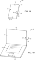
- FIGS. 1A and 1B Illustrative electronic devices of the type that may be provided with a display and a trim for the display are shown in FIGS. 1A and 1B .
- An electronic device such as electronic device10 of FIG. 1A or electronic device 10 of FIG. 1B may be computing device such as a laptop computer, a computer monitor containing an embedded computer, a tablet computer, a cellular telephone, a media player, or other handheld or portable electronic device, a smaller device such as a wrist-watch device, a pendant device, a headphone or earpiece device, or other wearable or miniature device, a television, a computer display that does not contain an embedded computer, a gaming device, a navigation device, an embedded system such as a system in which electronic equipment with a display is mounted in a kiosk or automobile, equipment that implements the functionality of two or more of these devices, or other electronic equipment.
- device 10 is a portable device such as a cellular telephone, media player, tablet computer, or other portable computing device.
- device 10 is a portable computing device such as a portable computer having an upper housing portion with a display and a housing that is attached to the upper housing by a hinge and that contains keyboard 23 and trackpad 24.
- FIGS. 1A and 1B are merely illustrative.
- Device 10 may have one or more displays such as display 14 mounted in housing structures such as housing 12.
- Housing 12 of device 10 which is sometimes referred to as a case, may be formed of materials such as plastic, glass, ceramics, carbon-fiber composites and other fiber-based composites, metal (e.g., machined aluminum, stainless steel, or other metals), other materials, or a combination of these materials.
- Device 10 may be formed using a unibody construction in which most or all of housing 12 is formed from a single structural element (e.g., a piece of machined metal or a piece of molded plastic) or may be formed from multiple housing structures (e.g., outer housing structures that have been mounted to internal frame elements or other internal housing structures).
- Display 14 may be a touch sensitive display that includes a touch sensor or may be insensitive to touch.
- Touch sensors for display 14 may be formed from an array of capacitive touch sensor electrodes, a resistive touch array, touch sensor structures based on acoustic touch, optical touch, or force-based touch technologies, or other suitable touch sensor components.
- Display 14 for device 10 includes display pixels formed from liquid crystal display (LCD) components or other suitable display pixel structures such as organic light-emitting diode display pixels, electrophoretic display pixels, plasma display pixels, etc.
- LCD liquid crystal display
- suitable display pixel structures such as organic light-emitting diode display pixels, electrophoretic display pixels, plasma display pixels, etc.
- a display cover layer may cover the surface of display 14 or a display layer such as a color filter layer (e.g., a layer formed from a clear substrate covered with patterned color filter elements) or other portion of a display may be used as the outermost (or nearly outermost) layer in display 14.
- the outermost display layer may be formed from a transparent glass sheet, a clear plastic layer, or other transparent member. If desired, openings may be formed in the outermost layer of display 14 to accommodate components such as button 16 and speaker port 18 of FIG. 1A (as examples). Buttons, connector ports, and other structures may also be accommodated using openings in housing 12.
- the display cover layer and/or other layers in display 14 may sometimes be formed from materials such as glass, whereas housing 12 of device 10 may sometimes be formed from materials such as metal.
- a plastic (polymer) trim may be interposed between the outer edge of display 14 (i.e., the rectangular periphery of display 14) and the opposing inner edge of housing 12.
- the trim may be formed from a plastic material that is softer than housing 12 (e.g., the trim may be formed from an elastomeric polymer).
- the trim may be molded onto housing 12 using injection molding (insert molding) techniques. The use of injection molding to form the trim may help in attaining tight tolerances and may simplify assembly. This may allow the size of the trim and therefore the width of the inactive border region in display 14 to be minimized, thereby enhancing device aesthetics.
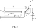
- FIG. 2 A cross-sectional side view of an illustrative electronic device such as device 10 of FIG. 1A or device 10 of FIG. 1B taken along line 20 of FIG. 1A or FIG. 1B and viewed in direction 22 of FIG. 1A or FIG. 1B is shown in FIG. 2 .
- display trim 24 may be molded onto inner surfaces 26 of housing 12. Inner surfaces 26 may form an inwardly facing peripheral ledge that runs around the periphery of housing 12.
- Display 14 may include outer display layer 30 and inner display layers 32. Display layers such as display layer 30 or other layers in display 14 may be supported by trim 24. In this arrangement, trim 24 may be interposed between the outer edge of display 14 and the opposing inner surface of housing 12 to help prevent damage to display 14.
- Outer display layer 30 of display 14 may be a layer of clear glass or plastic.
- display layer 30 may be a display cover glass layer or other display cover layer.
- Layers 32 may form a liquid crystal display, an organic light-emitting diode display, a plasma display, an electrophoretic display, or other display.
- layers 32 may include liquid crystal display layers such as a layer of liquid crystal material interposed between a color filter layer and a thin-film transistor layer and sandwiched between opposing upper and lower polarizers. If desired, the color filter layer or thin-film transistor layer may be used in place of display cover layer 30. Configurations for display 14 in which display 14 has a display cover layer are sometimes described herein as an example.
- Device 10 may include internal components 36 mounted on one or more substrates such as substrate 34.
- Internal components 36 may include integrated circuits, sensors, switches, connectors, and other electronic components.
- Substrate 34 may be a printed circuit board or other substrate.
- substrate 34 may be a rigid printed circuit board formed from a material such as fiberglass-filled epoxy or may be a flexible printed circuit board such as a flex circuit formed from a sheet of polyimide or a layer of other flexible polymer.
- Surfaces 26 in the example of FIG. 2 form an L-shaped ledge that supports molded trim 24.
- lower peripheral surface 40 of display cover layer 30 rests on surface 42 of trim 24 and outer edge surface 38 rests against surface 28 of trim 24.
- Other shapes and configurations for trim 24 and housing 12 may be used if desired.
- the illustrative configuration of FIG. 2 is merely illustrative.
- Trim 24 may be formed using an injection molding tool such as tool 42 in the perspective view of FIG. 3 .
- Tool 44 may have a reservoir for plastic pellets or other plastic material such as reservoir 44.
- the plastic may be, for example, a thermoplastic elastomer (TPE) such as a thermoplastic polyurethane, a thermoplastic polyamide, or other thermoplastic elastomer.
- Reservoir 44 may be used to provide the plastic pellets to heater 46 for melting. Heater 46 may raise the temperature of the plastic pellets above their melting temperature (e.g., to a temperature of greater than 250°C). Melted plastic may be forced into channels within a plastic molding structure such as upper die 50 through tubing 48 (as an example).
- Upper die 50 may mate with lower die 54.
- Plastic injection molding die structures such as upper die 50 and lower die 52 may be provided with alignment features such as illustrative pins 56 and mating openings 58 to help align portions of the die structures to each other and to workpiece 52.
- pins 56 may be used to help align upper die 50 with lower die 54.
- a workpiece such as workpiece 52 may be received within the die.
- workpiece 52 may be received within a cavity in the interior of upper die 50 and/or lower die 54, when die 50 and die 54 are joined.
- Workpiece 52 may be, for example, housing 12.
- Upper die 50 and lower die 54 may press against the surfaces of workpiece 52 (i.e., housing 12) to hold workpiece 52 in place during injection molding operations.
- trim 24 can be formed directly on housing 12. This may help trim 24 attach to housing 12 (e.g., by forming chemical bonds).
- the molding die may be maintained at a relatively low temperature relative to the temperature of heater 46 to help cool the plastic that forms trim 24.
- the molding die structures may be maintained at a temperature of about 30°C.
- FIG. 4 is a perspective view of an illustrative set of die structures for injection molding tool 42 of FIG. 4 .
- Tool 42 may have mating upper and lower injection molding die such as upper die 50 and lower die 54.
- Die 50 may be formed from one or more metal members and die 54 may be formed from one or more metal members. If desired, separate sections of each die may be independently positioned using computer-controlled positioners.
- the metal members or other structures that form the die 50 and die 54 may be pressed against the surfaces of housing 12 or other workpiece using computer-controlled positioners (actuators) to form seals that restrain the flow of molten plastic during injection molding.
- actuators computer-controlled positioners
- lower surface 62 of upper die 50 may be provided with a channel such as channel 60.
- Channel 60 may have the shape of a rectangular ring-shaped groove that matches the rectangular shape of the periphery of housing 12. Molten plastic may flow in channel 60 during molding.
- FIG. 5 is a top view of a portion of trim channel 60 of FIG. 4 in upper die 50 showing how channel 60 may have a locally enlarged portion such as locally enlarged portion 60' to accommodate injection of molded plastic when forming trim 24.
- Rectangular ring-shaped channel 60 in die 50 may be provided with one or more locally enlarged portions such as locally enlarged portion 60' (e.g., one or more locally enlarged portions 60', two or more locally enlarged portions 60', etc.).
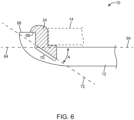
- FIG. 6 is a cross-sectional side view of a portion of device 10 in a configuration in which trim 24 and housing 12 have been provided with mating angled surface 70 on the inner surface of housing 12.
- Housing 12 may have a planar shape that runs parallel to horizontal axis 64 (in the orientation of FIG. 6 ). In this configuration, the planar shape of housing 12 may lie in a horizontal plane.
- Diagonal axis 72 may be oriented at a non-zero angle A with respect to horizontal axis 64 and the horizontal plane of housing 12.
- a portion of the inner edge of housing 12 i.e., a rectangular edge running around the rectangular periphery of housing 12 in region 70
- Trim 24 may likewise have an angled edge in region 70.
- inner surface 70 of housing 12 will be angled at a non-zero angle with respect to the horizontal plane containing housing 12 and will be angled at a non-zero axis with respect to horizontal axis 64.
- the length of region 70 along axis 72 will be longer than the length of a horizontally oriented lower surface on trim 24, so an angled lower surface configuration for trim 24 of the type shown in FIG. 6 may help increase surface area in contact region 70 between trim 24 and housing 12.
- the enhanced surface area in region 70 that is afforded by the non-zero angle A of axis 72 may create a large bonding surface that helps attach trim 24 securely to housing 12.
- Trim 24 may also have an upper lip portion that extends over inner edge 68 of upper housing edge surface 66 to help attach molded trim 24 to housing 12.
- region 70 of trim 24 and housing 12 is characterized by a smooth curved shape having a radius of curvature R that is greater than a minimum radius of curvature Rmin and that is less than a maximum radius of curvature Rmax.
- Minimum radius of curvature Rmin may be, for example, 10 mm, 5 mm, 1 mm, 0.5 mm, 0.1 mm, less than 0.1 mm, or other suitable size.
- Maximum radius of curvature Rmax may be 0.1 mm, 0.5 mm, 1 mm, 5mm, 10 mm, greater than 10 mm, or other suitable size.
- FIG. 8 shows how region 70 of trim 24 and housing 12 may be provided with a radius of curvature R that is between Rmin and Rmax while also orienting an extending part of region 70 along angled axis 72.
- Other configurations may be used for housing 12 and trim 24 if desired.
- the arrangements shown in FIGS. 6 , 7 , and 8 are merely illustrative.
- FIG. 9 is a perspective view of portions of injection molding tool 42.
- injection molding tool 42 may use computer-controlled positioners (actuators) to help control the lateral position of workpiece 52 (e.g., housing 12) relative to upper die 50 and lower die 54 (not shown in FIG. 9 ).
- computer-controlled positioner 74 may use sliding member 76 to press against edge 80 of workpiece 52 in direction 78 and opposing computer-controlled positioner 82 may use sliding member 84 to press against edge 88 of workpiece 54 in direction 86.
- Computer-controlled positioner 98 may use sliding member 100 to bear against surface 102 of workpiece 54 in direction 104 and opposing computer-controlled positioner 90 may use sliding structure 92 to press against edge 94 of workpiece 52 in direction 96. More positioners or fewer positioners may be used in injection molding tool 42 if desired. For example, vertical positioners may be used at each of the four corners of workpiece 52, combinations of vertical and horizontal (lateral) positioners may be used to adjust the position of workpiece 52, etc. The configuration of FIG. 9 in which two sets of opposing pairs of lateral positioners are used to adjust the lateral position of workpiece 52 is merely illustrative.
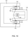
- FIG. 10 is a diagram showing how positioners in injection molding tool 42 may have geared surfaces such as straight geared surfaces 106 on members 114 and 116 and curved geared surfaces 108 on gears 110.
- Gears 110 may rotate around axes 112.
- Motors attached to gears 110 or a linear actuator such as linear actuator 120 may be used in moving member 114 relative to member 116, thereby moving sliding members or other structures in injection molding tool 42 against workpiece 52 (see, e.g., FIG. 9 ).
- Housing 12 may have the shape of a rectangular box or other suitable shape.
- housing 12 may have a rectangular box shape with curved corners, one or more curved edges, or other shapes.
- FIG. 11 is a top view of injection molding equipment 42 showing how injection molding tool 42 may have a segmented lower die.
- lower die 54 may have a central die portion 54-5 that has vacuum holes for holding workpiece 52 (housing 12) in place on central die portion 54-5.
- Lower die 54 may also have four corner portions 54-1, 54-2, 54-3, and 54-4.
- the vertical position (into and out of the page in the orientation of FIG. 11 ) of each of the portions of die 54 may be controlled independently to help ensure that the surfaces of lower die 54 conform to the exterior shape of housing 12.
- lower die sections 54-1, 54-2, 54-3, 54-4, and 54-5 may have mating curved surfaces that match the curved surfaces of the exterior of housing 12. This allows lower die 54 to place pressure vertically upward on the lower surfaces of housing 12 while avoiding any damage to housing 12 (i.e., workpiece 52) as upper die 50 applies pressure vertically downward to form a seal when injection molding plastic for trim 24.
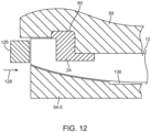
- FIG. 12 A cross-sectional side view of an edge portion of tool 24 of FIG. 11 taken along line 122 and viewed in direction 124 is shown in FIG. 12 .
- lower die portion 54-5 may have a central recess that forms a rectangular gap such as gap 130 under the center of housing 12. Gap 130 may provide clearance between the central upper surface of lower die 54 and the outer surface of housing 12 to avoid damaging housing 12.
- the upper surface of die portion 54-5 along the edge of housing 12 may have a curved shape that matches the curved shape of the exterior of housing 12.
- Lateral positioners such as positioner 126 may be used to adjust the lateral position of housing 12 relative to lower die 54 and upper die 50.
- lateral positioner 126 may press against the left edge of housing 12 in direction 128 and three other lateral positioners may press against three other edges of housing 12 to allow housing 12 to be centered or otherwise positioned within tool 42.
- Machine vision or other sensing techniques may be used to provide positioners in injection molding tool 42 with information on the position of dies 50 and 54 and workpiece 52.
- Upper die 50 may have a channel such as channel 60.
- molten plastic may be injected into channel 60 to form trim 24.
- trim 24 may form chemical bonds with mating surfaces of housing 12.
- Trim 24 may also be formed with a small size that satisfies desired tight tolerances due to the use of injection molding techniques to form trim 24 directly on housing 12 while aligning housing 12 relative to the die with computer-controlled positioners.
- FIG. 13 A flow chart of illustrative steps involved in forming an electronic device with an injection molded plastic display trim is shown in FIG. 13 .
- housing 12 may be located into lower die 54.
- Centering sliding members such as computer-controlled sliding members 76, 92, 82, and 100 of FIG. 9 or other lateral positioners may be used to center housing 12 within tool 42, thereby laterally positioning housing 12 in an accurate location with respect to lower die 54..
- upper die 50 may be lowered on top of housing 12 and lower die 54.
- Alignment features such as pins 56 and holes 58 of FIG. 3 may engage with each other to align upper die 50 and channel 60 with respect to housing 12.
- lower die positioners such as independent computer-controlled vertically traveling positioners coupled to lower die portions 54-1 , 54-2, 54-3, 54-4, and 54-5 may be moved vertically upwards against the lower surfaces of housing 12 to load the lower die and thereby press the upper and lower dies together to form a seal with housing 12.
- molten plastic from heater 46 may be injected into channel 60 in upper die 50, thereby overmolding trim 42 onto housing 12.
- Trim 42 may have a rectangular ring shape or may have other suitable shapes (e.g., trim 42 may be divided into multiple trim segments, trim 24 may have straight and/or curved trim sections, etc.).
- upper die 50 may be removed from housing 12.
- the lateral positioners of tool 42 may be released by moving them horizontally outward at step 144.
- housing 12 and integrally molded trim 42 may be removed from injection molding tool 42.
- Trim 42 is attached to housing 12 and surrounds a rectangular opening having dimensions matching the exterior lateral dimensions of display 14.
- Display 14 may be mounted in the rectangular opening in the center of trim 24 and display 14 (e.g., using a press fit, using adhesive, without using adhesive, and/or using other assembly techniques).
- Housing 12, display 14, and other components such as components 36 and substrate 34 of FIG. 2 may be assembled together to form a completed electronic device.
- a method of forming an electronic device includes injection molding a plastic display trim onto an electronic device housing structure for the electronic device using an injection molding tool, and mounting a display in the plastic display trim.
- injection molding the plastic display trim includes melting thermoplastic elastomer material to form plastic for the plastic display trim.
- the injection molding tool includes a die with a rectangular channel and injection molding the plastic display trim includes injecting the plastic into the rectangular channel.
- the electronic device housing lies in a plane and has an angled inner surface that is angled at a non-zero angle with respect to the plane and injection molding the plastic display trim includes injection molding the plastic display trim over the angled inner surface.
- the electronic device housing structure has a curved surface with a radius of curvature and injection molding the plastic display trim includes injection molding the plastic display trim over the curved surface.
- the radius of curvature is more than 0.1 mm and is less than 5 mm.
- the injection molding tool has upper die structures and lower die structures
- the method includes pressing the electronic device housing structure between the upper die structures and the lower die structures.
- the method includes laterally positioning the electronic device housing structure relative to the lower die structures using computer-controlled positioners.
- the lower die structures include a plurality of individually controlled sections, and pressing the electronic device housing structure between the upper die structures and the lower die structures includes moving each of the individually controlled sections against the electronic device housing structure.
- the individually controlled sections include four corner sections and pressing the electronic device housing structure between the upper and lower die structures include moving each of the four corner sections.
- apparatus in accordance with an embodiment, includes an electronic device housing, an overmolded plastic display trim that is injection molded onto the electronic device housing, and a display within the plastic display trim.
- the display includes a rectangular display cover glass mounted within the plastic display trim.
- the electronic device housing includes a planar metal housing and the overmolded plastic display trim is injection molded onto an inner surface of a peripheral portion of the planar metal housing.
- the overmolded plastic display trim has a rectangular ring shape with a rectangular opening in which the display is mounted.
- the electronic device housing lies in a plane and an angled interior surface of the housing lies along an axis that is oriented at a non-zero angle with respect to the plane and the overmolded plastic display trim is injected molded onto the angled interior surface.
- the electronic device housing lies in a plane and a curved interior surface of the electronic device housing is characterized by a radius of curvature of more than 0.1 mm and less than 5 mm and the overmolded plastic display trim is injected molded onto the curved interior surface.
- the apparatus includes a printed circuit, and electrical components mounted on the printed circuit, the printed circuit and the electrical components are located between the electronic device housing and the display.
- apparatus in accordance with an embodiment, includes a metal computing device housing structure, a plastic trim molded directly onto the metal computing device housing structure.
- the apparatus includes a display layer mounted within the plastic trim.
- the display layer includes a rectangular glass layer.
- a method of forming an electronic device comprising: injection molding a plastic display trim onto an electronic device housing structure for the electronic device using an injection molding tool; and mounting a display in the plastic display trim.
- injection molding the plastic display trim comprises melting thermoplastic elastomer material to form plastic for the plastic display trim.
- the injection molding tool comprises a die with a rectangular channel and wherein injection molding the plastic display trim comprises injecting the plastic into the rectangular channel.
- the electronic device housing lies in a plane and has an angled inner surface that is angled at a non-zero angle with respect to the plane and wherein injection molding the plastic display trim comprises injection molding the plastic display trim over the angled inner surface.
- the electronic device housing structure has a curved surface with a radius of curvature and wherein injection molding the plastic display trim comprises injection molding the plastic display trim over the curved surface.
- the radius of curvature is more than 0.1 mm and is less than 5 mm.
- the method further comprising: pressing the electronic device housing structure between the upper die structures and the lower die structures.
- the lower die structures include a plurality of individually controlled sections
- pressing the electronic device housing structure between the upper die structures and the lower die structures comprises moving each of the individually controlled sections against the electronic device housing structure
- the individually controlled sections comprise four corner sections and wherein pressing the electronic device housing structure between the upper and lower die structures comprises moving each of the four corner sections.
- an apparatus comprising: an electronic device housing; an overmolded plastic display trim that is injection molded onto the electronic device housing; and a display within the plastic display trim.
- the display comprises a rectangular display cover glass mounted within the plastic display trim.
- the electronic device housing comprises a planar metal housing and wherein the overmolded plastic display trim is injection molded onto an inner surface of a peripheral portion of the planar metal housing.
- the overmolded plastic display trim has a rectangular ring shape with a rectangular opening in which the display is mounted.
- the electronic device housing lies in a plane and wherein an angled interior surface of the housing lies along an axis that is oriented at a non-zero angle with respect to the plane and wherein the overmolded plastic display trim is injected molded onto the angled interior surface.
- the electronic device housing lies in a plane and wherein a curved interior surface of the electronic device housing is characterized by a radius of curvature of more than 0.1 mm and less than 5 mm and wherein the overmolded plastic display trim is injected molded onto the curved interior surface.
- a printed circuit a printed circuit
- electrical components mounted on the printed circuit, wherein the printed circuit and the electrical components are located between the electronic device housing and the display.
- an apparatus comprising: a metal computing device housing structure; a plastic trim molded directly onto the metal computing device housing structure.
- the display layer comprises a rectangular glass layer.
Landscapes
- Engineering & Computer Science (AREA)
- Theoretical Computer Science (AREA)
- Mechanical Engineering (AREA)
- Human Computer Interaction (AREA)
- Physics & Mathematics (AREA)
- General Engineering & Computer Science (AREA)
- General Physics & Mathematics (AREA)
- Computer Hardware Design (AREA)
- Manufacturing & Machinery (AREA)
- Power Engineering (AREA)
- Injection Moulding Of Plastics Or The Like (AREA)
- Moulds For Moulding Plastics Or The Like (AREA)
- Coils Or Transformers For Communication (AREA)
Abstract
Description
- This application claims priority to
United States patent application 13/967,595 filed August 15, 2013 - This relates generally to electronic devices and, more particularly, to electronic devices with displays.
- Electronic devices often include displays. For example, cellular telephones and portable computers include displays for presenting information to users.
- An elastomeric trim may be used when mounting a display in an electronic device. The elastomeric trim may surround the periphery of the display and may prevent the display from becoming damaged by direct contact with the housing.
- If care is not taken, the elastomeric trim may be larger than desired. This may make it difficult or impossible to reduce the border of the display as much as desired.
- Challenges may also arise when assembling a piece of thin trim into a device, because it may be difficult to control the orientation of the trim with respect to the structures in the device.
- It would therefore be desirable to be able to provide improved display trims for electronic devices with displays.
- An electronic device may be provided with a display. The electronic device may include a housing in which the display and other components are mounted. The housing may be formed from a material such as metal, plastic, glass, or fiber-based composites.
- A display trim may be formed from injection molded plastic that is molded directly onto the housing. An injection molding tool may heat thermoplastic elastomer pellets sufficiently to melt the plastic. Molten plastic may be formed in a desired trim shape using a channel in a mold die.
- The molded plastic trim may form a rectangular ring around the periphery of the housing. The housing may have angled or curved interior surfaces that are covered by the molded plastic trim.
- Computer-controlled positioners may be used to center the housing within the injection molding tool. Independently controlled positioners may also be used in capturing the housing between the lower die and the upper die in the injection molding tool. The injection molding tool may inject molten thermoplastic elastomer material into a channel in the upper die to form the plastic display trim while the lower die and upper die are pressed against the housing.
-
-
FIG. 1A is a perspective view of an illustrative electronic device such as a handheld computing device in accordance with an embodiment. -
FIG. 1B is a perspective view of an illustrative electronic device such as a portable computer or other portable computing device with a display in accordance with an embodiment. -
FIG. 2 is a cross-sectional side view of an illustrative electronic device with a display and display trim in accordance with an embodiment. -
FIG. 3 is an exploded perspective view of a molding tool that may be used in forming a display trim for an electronic device display in accordance with an embodiment. -
FIG. 4 is a perspective view of upper and lower molding dies in an illustrative molding tool having a groove in the upper die for forming an injection molded display on an electronic device housing in accordance with an embodiment. -
FIG. 5 is a top view of a portion of a molding die having a channel with a recess for accommodating injected molded plastic for a display trim on an electronic device housing in accordance with an embodiment. -
FIG. 6 is a cross-sectional side view of a portion of an electronic device housing showing how a molded display trim may have an angled lower surface in accordance with an embodiment. -
FIG. 7 is a cross-sectional side view of a portion of an electronic device showing how a molded display trim may have a curved portion that is characterized by a radius of curvature in accordance with an embodiment. -
FIG. 8 is cross-sectional side view of a portion of an electronic device showing how an illustrative molded display trim may have an angled lower surface and a curved portion that is characterized by a radius of curvature in accordance with an embodiment. -
FIG. 9 is a perspective view of two pairs of lateral actuators that are associated with an illustrative injection molding tool for forming a molded display trim for a display in accordance with an embodiment. -
FIG. 10 is a cross-sectional side view of an illustrative geared actuator that may be used in moving molding tool structures during the process of insert molding a display trim for a display in accordance with an embodiment. -
FIG. 11 is a top view of an illustrative display trim molding tool in accordance with an embodiment. -
FIG. 12 is a cross-sectional side view of an edge portion of the illustrative display trim molding tool ofFIG. 11 in accordance with an embodiment. -
FIG. 13 is a flow chart of illustrative steps involved in forming a molded plastic display trim for an electronic device display in accordance with an embodiment. - Displays in electronic devices may be provided with trims. An elastomeric display trim may surround a display and prevent the display from becoming damaged by direct contact with a metal housing. For example, a display trim may prevent the display from becoming damaged by contact with a metal computing device housing or other electronic device housing structure. The display trim may be formed from plastic that is molded onto electronic device structures such as housing structures. By accurately placing the trim on the housing, tolerances may be improved, thereby allowing the size of the trim to be minimized. Difficulties that might otherwise arise when attaching a thin separate trim member to a housing can also be avoided, thereby simplifying assembly operations.
- Illustrative electronic devices of the type that may be provided with a display and a trim for the display are shown in
FIGS. 1A and 1B . An electronic device such as electronic device10 ofFIG. 1A orelectronic device 10 ofFIG. 1B may be computing device such as a laptop computer, a computer monitor containing an embedded computer, a tablet computer, a cellular telephone, a media player, or other handheld or portable electronic device, a smaller device such as a wrist-watch device, a pendant device, a headphone or earpiece device, or other wearable or miniature device, a television, a computer display that does not contain an embedded computer, a gaming device, a navigation device, an embedded system such as a system in which electronic equipment with a display is mounted in a kiosk or automobile, equipment that implements the functionality of two or more of these devices, or other electronic equipment. In the illustrative configuration ofFIG. 1A ,device 10 is a portable device such as a cellular telephone, media player, tablet computer, or other portable computing device. In the illustrative configuration ofFIG. 1B ,device 10 is a portable computing device such as a portable computer having an upper housing portion with a display and a housing that is attached to the upper housing by a hinge and that containskeyboard 23 andtrackpad 24. Other configurations may be used fordevice 10 if desired. The examples ofFIGS. 1A and 1B are merely illustrative. -
Device 10 may have one or more displays such asdisplay 14 mounted in housing structures such ashousing 12.Housing 12 ofdevice 10, which is sometimes referred to as a case, may be formed of materials such as plastic, glass, ceramics, carbon-fiber composites and other fiber-based composites, metal (e.g., machined aluminum, stainless steel, or other metals), other materials, or a combination of these materials.Device 10 may be formed using a unibody construction in which most or all ofhousing 12 is formed from a single structural element (e.g., a piece of machined metal or a piece of molded plastic) or may be formed from multiple housing structures (e.g., outer housing structures that have been mounted to internal frame elements or other internal housing structures). -
Display 14 may be a touch sensitive display that includes a touch sensor or may be insensitive to touch. Touch sensors fordisplay 14 may be formed from an array of capacitive touch sensor electrodes, a resistive touch array, touch sensor structures based on acoustic touch, optical touch, or force-based touch technologies, or other suitable touch sensor components. -
Display 14 fordevice 10 includes display pixels formed from liquid crystal display (LCD) components or other suitable display pixel structures such as organic light-emitting diode display pixels, electrophoretic display pixels, plasma display pixels, etc. - A display cover layer may cover the surface of
display 14 or a display layer such as a color filter layer (e.g., a layer formed from a clear substrate covered with patterned color filter elements) or other portion of a display may be used as the outermost (or nearly outermost) layer indisplay 14. The outermost display layer may be formed from a transparent glass sheet, a clear plastic layer, or other transparent member. If desired, openings may be formed in the outermost layer ofdisplay 14 to accommodate components such asbutton 16 andspeaker port 18 ofFIG. 1A (as examples). Buttons, connector ports, and other structures may also be accommodated using openings inhousing 12. - The display cover layer and/or other layers in
display 14 may sometimes be formed from materials such as glass, whereashousing 12 ofdevice 10 may sometimes be formed from materials such as metal. To help prevent damage to display 14 that might otherwise arise due to direct contact between the glass or other materials indisplay 14 and the metal or other materials inhousing 12, a plastic (polymer) trim may be interposed between the outer edge of display 14 (i.e., the rectangular periphery of display 14) and the opposing inner edge ofhousing 12. The trim may be formed from a plastic material that is softer than housing 12 (e.g., the trim may be formed from an elastomeric polymer). The trim may be molded ontohousing 12 using injection molding (insert molding) techniques. The use of injection molding to form the trim may help in attaining tight tolerances and may simplify assembly. This may allow the size of the trim and therefore the width of the inactive border region indisplay 14 to be minimized, thereby enhancing device aesthetics. - A cross-sectional side view of an illustrative electronic device such as
device 10 ofFIG. 1A ordevice 10 ofFIG. 1B taken alongline 20 ofFIG. 1A or FIG. 1B and viewed indirection 22 ofFIG. 1A or FIG. 1B is shown inFIG. 2 . As shown inFIG. 2 , display trim 24 may be molded ontoinner surfaces 26 ofhousing 12.Inner surfaces 26 may form an inwardly facing peripheral ledge that runs around the periphery ofhousing 12.Display 14 may includeouter display layer 30 and inner display layers 32. Display layers such asdisplay layer 30 or other layers indisplay 14 may be supported bytrim 24. In this arrangement, trim 24 may be interposed between the outer edge ofdisplay 14 and the opposing inner surface ofhousing 12 to help prevent damage to display 14. -
Outer display layer 30 ofdisplay 14 may be a layer of clear glass or plastic. For example,display layer 30 may be a display cover glass layer or other display cover layer.Layers 32 may form a liquid crystal display, an organic light-emitting diode display, a plasma display, an electrophoretic display, or other display. For example, layers 32 may include liquid crystal display layers such as a layer of liquid crystal material interposed between a color filter layer and a thin-film transistor layer and sandwiched between opposing upper and lower polarizers. If desired, the color filter layer or thin-film transistor layer may be used in place ofdisplay cover layer 30. Configurations fordisplay 14 in which display 14 has a display cover layer are sometimes described herein as an example. -
Device 10 may include internal components 36 mounted on one or more substrates such assubstrate 34. Internal components 36 may include integrated circuits, sensors, switches, connectors, and other electronic components.Substrate 34 may be a printed circuit board or other substrate. For example,substrate 34 may be a rigid printed circuit board formed from a material such as fiberglass-filled epoxy or may be a flexible printed circuit board such as a flex circuit formed from a sheet of polyimide or a layer of other flexible polymer. -
Surfaces 26 in the example ofFIG. 2 form an L-shaped ledge that supports moldedtrim 24. Whendisplay 14 is mounted indevice 10, lowerperipheral surface 40 ofdisplay cover layer 30 rests onsurface 42 oftrim 24 andouter edge surface 38 rests againstsurface 28 oftrim 24. Other shapes and configurations fortrim 24 andhousing 12 may be used if desired. The illustrative configuration ofFIG. 2 is merely illustrative. -
Trim 24 may be formed using an injection molding tool such astool 42 in the perspective view ofFIG. 3 .Tool 44 may have a reservoir for plastic pellets or other plastic material such asreservoir 44. The plastic may be, for example, a thermoplastic elastomer (TPE) such as a thermoplastic polyurethane, a thermoplastic polyamide, or other thermoplastic elastomer.Reservoir 44 may be used to provide the plastic pellets toheater 46 for melting.Heater 46 may raise the temperature of the plastic pellets above their melting temperature (e.g., to a temperature of greater than 250°C). Melted plastic may be forced into channels within a plastic molding structure such as upper die 50 through tubing 48 (as an example). - Upper die 50 may mate with
lower die 54. Plastic injection molding die structures such asupper die 50 andlower die 52 may be provided with alignment features such asillustrative pins 56 andmating openings 58 to help align portions of the die structures to each other and to workpiece 52. For example, pins 56 may be used to help alignupper die 50 withlower die 54. - During injection molding operation, a workpiece such as
workpiece 52 may be received within the die. For example,workpiece 52 may be received within a cavity in the interior ofupper die 50 and/or lower die 54, when die 50 and die 54 are joined.Workpiece 52 may be, for example,housing 12. Upper die 50 andlower die 54 may press against the surfaces of workpiece 52 (i.e., housing 12) to holdworkpiece 52 in place during injection molding operations. As heated molten plastic fromreservoir 44 flows into the die, trim 24 can be formed directly onhousing 12. This may help trim 24 attach to housing 12 (e.g., by forming chemical bonds). The molding die may be maintained at a relatively low temperature relative to the temperature ofheater 46 to help cool the plastic that forms trim 24. For example, the molding die structures may be maintained at a temperature of about 30°C. -
FIG. 4 is a perspective view of an illustrative set of die structures forinjection molding tool 42 ofFIG. 4 .Tool 42 may have mating upper and lower injection molding die such asupper die 50 andlower die 54.Die 50 may be formed from one or more metal members and die 54 may be formed from one or more metal members. If desired, separate sections of each die may be independently positioned using computer-controlled positioners. - The metal members or other structures that form the
die 50 and die 54 may be pressed against the surfaces ofhousing 12 or other workpiece using computer-controlled positioners (actuators) to form seals that restrain the flow of molten plastic during injection molding. As shown in the example ofFIG. 4 ,lower surface 62 ofupper die 50 may be provided with a channel such aschannel 60.Channel 60 may have the shape of a rectangular ring-shaped groove that matches the rectangular shape of the periphery ofhousing 12. Molten plastic may flow inchannel 60 during molding. - During injection molding operations, a thermoplastic elastomer or other injection molded plastic in
channel 60 may be used to form an injection molded plastic trim such astrim 24 onhousing 12.FIG. 5 is a top view of a portion oftrim channel 60 ofFIG. 4 in upper die 50 showing howchannel 60 may have a locally enlarged portion such as locally enlarged portion 60' to accommodate injection of molded plastic when formingtrim 24. Rectangular ring-shapedchannel 60 indie 50 may be provided with one or more locally enlarged portions such as locally enlarged portion 60' (e.g., one or more locally enlarged portions 60', two or more locally enlarged portions 60', etc.). -
FIG. 6 is a cross-sectional side view of a portion ofdevice 10 in a configuration in which trim 24 andhousing 12 have been provided with mating angledsurface 70 on the inner surface ofhousing 12.Housing 12 may have a planar shape that runs parallel to horizontal axis 64 (in the orientation ofFIG. 6 ). In this configuration, the planar shape ofhousing 12 may lie in a horizontal plane. -
Diagonal axis 72 may be oriented at a non-zero angle A with respect tohorizontal axis 64 and the horizontal plane ofhousing 12. A portion of the inner edge of housing 12 (i.e., a rectangular edge running around the rectangular periphery ofhousing 12 in region 70) may lie in a plane that runs alongangled axis 72.Trim 24 may likewise have an angled edge inregion 70. As a result,inner surface 70 ofhousing 12 will be angled at a non-zero angle with respect to the horizontalplane containing housing 12 and will be angled at a non-zero axis with respect tohorizontal axis 64. - The length of
region 70 alongaxis 72 will be longer than the length of a horizontally oriented lower surface ontrim 24, so an angled lower surface configuration fortrim 24 of the type shown inFIG. 6 may help increase surface area incontact region 70 betweentrim 24 andhousing 12. The enhanced surface area inregion 70 that is afforded by the non-zero angle A ofaxis 72 may create a large bonding surface that helps attach trim 24 securely tohousing 12.Trim 24 may also have an upper lip portion that extends overinner edge 68 of upperhousing edge surface 66 to help attach moldedtrim 24 tohousing 12. - In the illustrative configuration of
FIG. 7 ,region 70 oftrim 24 andhousing 12 is characterized by a smooth curved shape having a radius of curvature R that is greater than a minimum radius of curvature Rmin and that is less than a maximum radius of curvature Rmax. Minimum radius of curvature Rmin may be, for example, 10 mm, 5 mm, 1 mm, 0.5 mm, 0.1 mm, less than 0.1 mm, or other suitable size. Maximum radius of curvature Rmax may be 0.1 mm, 0.5 mm, 1 mm, 5mm, 10 mm, greater than 10 mm, or other suitable size. By ensuring that the radius of curvature R is not too small, stresses intrim 24 can be minimized. Radius of curvature R is preferably not too large, so that the right angle bend between the vertical and horizontal portions of the inner surface ofhousing 12 can be formed compactly. -
FIG. 8 shows howregion 70 oftrim 24 andhousing 12 may be provided with a radius of curvature R that is between Rmin and Rmax while also orienting an extending part ofregion 70 alongangled axis 72. Other configurations may be used forhousing 12 and trim 24 if desired. The arrangements shown inFIGS. 6 ,7 , and8 are merely illustrative. -
FIG. 9 is a perspective view of portions ofinjection molding tool 42. As shown inFIG. 9 ,injection molding tool 42 may use computer-controlled positioners (actuators) to help control the lateral position of workpiece 52 (e.g., housing 12) relative toupper die 50 and lower die 54 (not shown inFIG. 9 ). For example, computer-controlledpositioner 74 may use slidingmember 76 to press againstedge 80 ofworkpiece 52 indirection 78 and opposing computer-controlledpositioner 82 may use slidingmember 84 to press againstedge 88 ofworkpiece 54 indirection 86. Computer-controlledpositioner 98 may use slidingmember 100 to bear againstsurface 102 ofworkpiece 54 indirection 104 and opposing computer-controlledpositioner 90 may use slidingstructure 92 to press againstedge 94 ofworkpiece 52 indirection 96. More positioners or fewer positioners may be used ininjection molding tool 42 if desired. For example, vertical positioners may be used at each of the four corners ofworkpiece 52, combinations of vertical and horizontal (lateral) positioners may be used to adjust the position ofworkpiece 52, etc. The configuration ofFIG. 9 in which two sets of opposing pairs of lateral positioners are used to adjust the lateral position ofworkpiece 52 is merely illustrative. -
FIG. 10 is a diagram showing how positioners ininjection molding tool 42 may have geared surfaces such as straight gearedsurfaces 106 onmembers surfaces 108 ongears 110.Gears 110 may rotate aroundaxes 112. Motors attached togears 110 or a linear actuator such aslinear actuator 120 may be used in movingmember 114 relative tomember 116, thereby moving sliding members or other structures ininjection molding tool 42 against workpiece 52 (see, e.g.,FIG. 9 ). -
Housing 12 may have the shape of a rectangular box or other suitable shape. For example,housing 12 may have a rectangular box shape with curved corners, one or more curved edges, or other shapes.FIG. 11 is a top view ofinjection molding equipment 42 showing howinjection molding tool 42 may have a segmented lower die. As shown inFIG. 11 ,lower die 54 may have a central die portion 54-5 that has vacuum holes for holding workpiece 52 (housing 12) in place on central die portion 54-5. Lower die 54 may also have four corner portions 54-1, 54-2, 54-3, and 54-4. The vertical position (into and out of the page in the orientation ofFIG. 11 ) of each of the portions ofdie 54 may be controlled independently to help ensure that the surfaces oflower die 54 conform to the exterior shape ofhousing 12. In configurations in whichhousing 12 has curved exterior surfaces, lower die sections 54-1, 54-2, 54-3, 54-4, and 54-5 may have mating curved surfaces that match the curved surfaces of the exterior ofhousing 12. This allowslower die 54 to place pressure vertically upward on the lower surfaces ofhousing 12 while avoiding any damage to housing 12 (i.e., workpiece 52) as upper die 50 applies pressure vertically downward to form a seal when injection molding plastic fortrim 24. - A cross-sectional side view of an edge portion of
tool 24 ofFIG. 11 taken alongline 122 and viewed indirection 124 is shown inFIG. 12 . As shown inFIG. 12 , lower die portion 54-5 may have a central recess that forms a rectangular gap such asgap 130 under the center ofhousing 12.Gap 130 may provide clearance between the central upper surface oflower die 54 and the outer surface ofhousing 12 to avoiddamaging housing 12. The upper surface of die portion 54-5 along the edge ofhousing 12 may have a curved shape that matches the curved shape of the exterior ofhousing 12. Lateral positioners such aspositioner 126 may be used to adjust the lateral position ofhousing 12 relative to lower die 54 andupper die 50. For example,lateral positioner 126 may press against the left edge ofhousing 12 indirection 128 and three other lateral positioners may press against three other edges ofhousing 12 to allowhousing 12 to be centered or otherwise positioned withintool 42. Machine vision or other sensing techniques may be used to provide positioners ininjection molding tool 42 with information on the position of dies 50 and 54 andworkpiece 52. - Upper die 50 may have a channel such as
channel 60. During injection molding operations, molten plastic may be injected intochannel 60 to formtrim 24. As part of the injection molding process, trim 24 may form chemical bonds with mating surfaces ofhousing 12.Trim 24 may also be formed with a small size that satisfies desired tight tolerances due to the use of injection molding techniques to form trim 24 directly onhousing 12 while aligninghousing 12 relative to the die with computer-controlled positioners. - A flow chart of illustrative steps involved in forming an electronic device with an injection molded plastic display trim is shown in
FIG. 13 . - At
step 132,housing 12 may be located intolower die 54. Centering sliding members such as computer-controlled slidingmembers FIG. 9 or other lateral positioners may be used to centerhousing 12 withintool 42, thereby laterally positioninghousing 12 in an accurate location with respect to lower die 54.. - At
step 136, upper die 50 may be lowered on top ofhousing 12 andlower die 54. Alignment features such aspins 56 and holes 58 ofFIG. 3 may engage with each other to alignupper die 50 andchannel 60 with respect tohousing 12. - At
step 138, lower die positioners such as independent computer-controlled vertically traveling positioners coupled to lower die portions 54-1 , 54-2, 54-3, 54-4, and 54-5 may be moved vertically upwards against the lower surfaces ofhousing 12 to load the lower die and thereby press the upper and lower dies together to form a seal withhousing 12. - At
step 140, molten plastic fromheater 46 may be injected intochannel 60 inupper die 50, thereby overmolding trim 42 ontohousing 12.Trim 42 may have a rectangular ring shape or may have other suitable shapes (e.g., trim 42 may be divided into multiple trim segments, trim 24 may have straight and/or curved trim sections, etc.). - At
step 142, upper die 50 may be removed fromhousing 12. - The lateral positioners of tool 42 (see, e.g.,
FIG. 9 ) may be released by moving them horizontally outward atstep 144. - At
step 146,housing 12 and integrally moldedtrim 42 may be removed frominjection molding tool 42.Trim 42 is attached tohousing 12 and surrounds a rectangular opening having dimensions matching the exterior lateral dimensions ofdisplay 14.Display 14 may be mounted in the rectangular opening in the center oftrim 24 and display 14 (e.g., using a press fit, using adhesive, without using adhesive, and/or using other assembly techniques).Housing 12,display 14, and other components such as components 36 andsubstrate 34 ofFIG. 2 may be assembled together to form a completed electronic device. - In accordance with an embodiment, a method of forming an electronic device is provided that includes injection molding a plastic display trim onto an electronic device housing structure for the electronic device using an injection molding tool, and mounting a display in the plastic display trim.
- In accordance with another embodiment, injection molding the plastic display trim includes melting thermoplastic elastomer material to form plastic for the plastic display trim.
- In accordance with another embodiment, the injection molding tool includes a die with a rectangular channel and injection molding the plastic display trim includes injecting the plastic into the rectangular channel.
- In accordance with another embodiment, the electronic device housing lies in a plane and has an angled inner surface that is angled at a non-zero angle with respect to the plane and injection molding the plastic display trim includes injection molding the plastic display trim over the angled inner surface.
- In accordance with another embodiment, the electronic device housing structure has a curved surface with a radius of curvature and injection molding the plastic display trim includes injection molding the plastic display trim over the curved surface.
- In accordance with another embodiment, the radius of curvature is more than 0.1 mm and is less than 5 mm.
- In accordance with another embodiment, the injection molding tool has upper die structures and lower die structures, the method includes pressing the electronic device housing structure between the upper die structures and the lower die structures.
- In accordance with another embodiment, the method includes laterally positioning the electronic device housing structure relative to the lower die structures using computer-controlled positioners.
- In accordance with another embodiment, the lower die structures include a plurality of individually controlled sections, and pressing the electronic device housing structure between the upper die structures and the lower die structures includes moving each of the individually controlled sections against the electronic device housing structure.
- In accordance with another embodiment, the individually controlled sections include four corner sections and pressing the electronic device housing structure between the upper and lower die structures include moving each of the four corner sections.
- In accordance with an embodiment, apparatus is provided that includes an electronic device housing, an overmolded plastic display trim that is injection molded onto the electronic device housing, and a display within the plastic display trim.
- In accordance with another embodiment, the display includes a rectangular display cover glass mounted within the plastic display trim.
- In accordance with another embodiment, the electronic device housing includes a planar metal housing and the overmolded plastic display trim is injection molded onto an inner surface of a peripheral portion of the planar metal housing.
- In accordance with another embodiment, the overmolded plastic display trim has a rectangular ring shape with a rectangular opening in which the display is mounted.
- In accordance with another embodiment, the electronic device housing lies in a plane and an angled interior surface of the housing lies along an axis that is oriented at a non-zero angle with respect to the plane and the overmolded plastic display trim is injected molded onto the angled interior surface.
- In accordance with another embodiment, the electronic device housing lies in a plane and a curved interior surface of the electronic device housing is characterized by a radius of curvature of more than 0.1 mm and less than 5 mm and the overmolded plastic display trim is injected molded onto the curved interior surface.
- In accordance with another embodiment, the apparatus includes a printed circuit, and electrical components mounted on the printed circuit, the printed circuit and the electrical components are located between the electronic device housing and the display.
- In accordance with an embodiment, apparatus is provided that includes a metal computing device housing structure, a plastic trim molded directly onto the metal computing device housing structure.
- In accordance with another embodiment, the apparatus includes a display layer mounted within the plastic trim.
- In accordance with another embodiment, the display layer includes a rectangular glass layer.
- The foregoing is merely illustrative and various modifications can be made by those skilled in the art without departing from the scope and spirit of the described embodiments. The foregoing embodiments may be implemented individually or in any combination.
- According to an aspect of the invention there is provided a method of forming an electronic device, comprising: injection molding a plastic display trim onto an electronic device housing structure for the electronic device using an injection molding tool; and mounting a display in the plastic display trim.
- Preferably, wherein injection molding the plastic display trim comprises melting thermoplastic elastomer material to form plastic for the plastic display trim.
- Preferably, wherein the injection molding tool comprises a die with a rectangular channel and wherein injection molding the plastic display trim comprises injecting the plastic into the rectangular channel.
- Preferably, wherein the electronic device housing lies in a plane and has an angled inner surface that is angled at a non-zero angle with respect to the plane and wherein injection molding the plastic display trim comprises injection molding the plastic display trim over the angled inner surface.
- Preferably, wherein the electronic device housing structure has a curved surface with a radius of curvature and wherein injection molding the plastic display trim comprises injection molding the plastic display trim over the curved surface.
- Preferably, wherein the radius of curvature is more than 0.1 mm and is less than 5 mm.
- Preferably, wherein the injection molding tool has upper die structures and lower die structures, the method further comprising: pressing the electronic device housing structure between the upper die structures and the lower die structures.
- Preferably, further comprising: laterally positioning the electronic device housing structure relative to the lower die structures using computer-controlled positioners.
- Preferably, wherein the lower die structures include a plurality of individually controlled sections, and wherein pressing the electronic device housing structure between the upper die structures and the lower die structures comprises moving each of the individually controlled sections against the electronic device housing structure.
- Preferably, wherein the individually controlled sections comprise four corner sections and wherein pressing the electronic device housing structure between the upper and lower die structures comprises moving each of the four corner sections.
- According to an aspect of the invention there is provided an apparatus, comprising: an electronic device housing; an overmolded plastic display trim that is injection molded onto the electronic device housing; and a display within the plastic display trim.
- Preferably, wherein the display comprises a rectangular display cover glass mounted within the plastic display trim.
- Preferably, wherein the electronic device housing comprises a planar metal housing and wherein the overmolded plastic display trim is injection molded onto an inner surface of a peripheral portion of the planar metal housing.
- Preferably, wherein the overmolded plastic display trim has a rectangular ring shape with a rectangular opening in which the display is mounted.
- Preferably, wherein the electronic device housing lies in a plane and wherein an angled interior surface of the housing lies along an axis that is oriented at a non-zero angle with respect to the plane and wherein the overmolded plastic display trim is injected molded onto the angled interior surface.
- Preferably, wherein the electronic device housing lies in a plane and wherein a curved interior surface of the electronic device housing is characterized by a radius of curvature of more than 0.1 mm and less than 5 mm and wherein the overmolded plastic display trim is injected molded onto the curved interior surface.
- Preferably, further comprising: a printed circuit; and electrical components mounted on the printed circuit, wherein the printed circuit and the electrical components are located between the electronic device housing and the display.
- According to an aspect of the invention there is provided an apparatus, comprising: a metal computing device housing structure; a plastic trim molded directly onto the metal computing device housing structure.
- Preferably, further comprising a display layer mounted within the plastic trim.
- Preferably, wherein the display layer comprises a rectangular glass layer.
Claims (15)
- An electronic device (10), comprising:a housing (12) having an inner surface (26) that forms a ledge;molded polymer (24) that is supported by the ledge, wherein the molded polymer (24) has a rectangular ring shape with a rectangular opening; anda display (14) having a display layer (30) that is supported by the molded polymer (24) and that is mounted within the rectangular opening.
- The electronic device (10) defined in claim 1 wherein the molded polymer comprises injection molded plastic.
- The electronic device (10) defined in claim 1 or claim 2 wherein the ledge comprises an L-shaped ledge.
- The electronic device (10) defined in claim 3 wherein the display layer has a lower peripheral surface (40) that rests on the molded polymer (24) and an outer edge surface (38) that rests against the molded polymer (24).
- The electronic device (10) defined in any preceding claim wherein the molded polymer (24) comprises thermoplastic polyurethane.
- The electronic device (10) defined in any preceding claim wherein the molded polymer (24) has a curved surface.
- The electronic device (10) defined in any preceding claim wherein the display (14) is attached to the molded polymer (24) without adhesive.
- The electronic device (10) defined in any preceding claim wherein the molded polymer (24) is molded onto the inner surface (26).
- The electronic device (10) defined in any preceding claim wherein the ledge extends around a periphery of the housing (12).
- The electronic device (10) defined in any preceding claim wherein the display layer (30) comprises a thin-film transistor layer.
- The electronic device (10) defined in any preceding claim wherein the display layer (30) comprises a color filter layer.
- The electronic device (10) defined in any preceding claim wherein the display (14) comprises an organic light-emitting diode display.
- The electronic device (10) defined in any preceding claim wherein the molded polymer (24) is interposed between an outer edge of the display layer (30) and the inner surface (26) of the housing (12).
- The electronic device (10) defined in any preceding claim wherein the molded polymer (24) comprises elastomeric polymer.
- The electronic device (10) defined in any preceding claim wherein the display layer (30) comprises a material selected from the group consisting of: glass and plastic.
Applications Claiming Priority (3)
| Application Number | Priority Date | Filing Date | Title |
|---|---|---|---|
| US13/967,595 US9547338B2 (en) | 2013-08-15 | 2013-08-15 | Electronic device with injection molded display trim |
| EP14750112.6A EP3014379B1 (en) | 2013-08-15 | 2014-07-24 | Electronic device with injection molded display trim |
| PCT/US2014/048054 WO2015023416A1 (en) | 2013-08-15 | 2014-07-24 | Electronic device with injection molded display trim |
Related Parent Applications (1)
| Application Number | Title | Priority Date | Filing Date |
|---|---|---|---|
| EP14750112.6A Division EP3014379B1 (en) | 2013-08-15 | 2014-07-24 | Electronic device with injection molded display trim |
Publications (2)
| Publication Number | Publication Date |
|---|---|
| EP4249201A2 true EP4249201A2 (en) | 2023-09-27 |
| EP4249201A3 EP4249201A3 (en) | 2023-12-27 |
Family
ID=51300886
Family Applications (2)
| Application Number | Title | Priority Date | Filing Date |
|---|---|---|---|
| EP14750112.6A Active EP3014379B1 (en) | 2013-08-15 | 2014-07-24 | Electronic device with injection molded display trim |
| EP23178711.0A Pending EP4249201A3 (en) | 2013-08-15 | 2014-07-24 | Electronic device with injection molded display trim |
Family Applications Before (1)
| Application Number | Title | Priority Date | Filing Date |
|---|---|---|---|
| EP14750112.6A Active EP3014379B1 (en) | 2013-08-15 | 2014-07-24 | Electronic device with injection molded display trim |
Country Status (5)
| Country | Link |
|---|---|
| US (1) | US9547338B2 (en) |
| EP (2) | EP3014379B1 (en) |
| JP (1) | JP6378339B2 (en) |
| CN (1) | CN105452980A (en) |
| WO (1) | WO2015023416A1 (en) |
Families Citing this family (15)
| Publication number | Priority date | Publication date | Assignee | Title |
|---|---|---|---|---|
| JP2015151449A (en) * | 2014-02-13 | 2015-08-24 | 早川ゴム株式会社 | Method for forming adhesive layer and article |
| JP6468927B2 (en) * | 2015-04-06 | 2019-02-13 | 株式会社サカイヤ | Molding method and molding die for sensor-integrated resin molded product |
| CN106132141A (en) * | 2016-08-03 | 2016-11-16 | 南昌欧菲光学技术有限公司 | Electronic product, glass shell and manufacture equipment thereof and method |
| US10405439B2 (en) * | 2017-01-09 | 2019-09-03 | Guangdong Oppo Mobile Telecommunications Corp., Ltd. | Display panel assembly and manufacturing method thereof |
| CN109429446B (en) * | 2017-08-25 | 2020-12-25 | 比亚迪股份有限公司 | 3D glass-metal composite, preparation method thereof and electronic product |
| CN107633777A (en) * | 2017-10-12 | 2018-01-26 | 深圳市创显光电有限公司 | A kind of led display devices and its manufacture method |
| US20190191266A1 (en) * | 2017-12-14 | 2019-06-20 | GM Global Technology Operations LLC | Method and apparatus for wireless vehicle communication |
| US11054861B2 (en) * | 2018-06-11 | 2021-07-06 | Apple Inc. | Electronic devices having displays with expanded edges |
| CN110875967A (en) * | 2018-09-03 | 2020-03-10 | 比亚迪股份有限公司 | Housing and preparation method thereof, electronic device and preparation method thereof |
| US11630485B2 (en) | 2018-09-10 | 2023-04-18 | Apple Inc. | Housing structures and input-output devices for electronic devices |
| US12353241B1 (en) * | 2019-09-25 | 2025-07-08 | Apple Inc. | Electronic devices with display support structures |
| CN113311688B (en) * | 2020-02-26 | 2022-08-12 | Oppo广东移动通信有限公司 | Middle frame and preparation method thereof, watch body and wearable device |
| US11775031B2 (en) * | 2021-01-04 | 2023-10-03 | Apple Inc. | Electronic device display |
| CN216352273U (en) * | 2021-10-08 | 2022-04-19 | 深圳市华胜软件技术有限公司 | Infrared touch screen and display device |
| CN114434732A (en) * | 2022-01-22 | 2022-05-06 | 宁波市全盛壳体有限公司 | Manufacturing process flow of IP68 high-protection electric energy meter terminal |
Family Cites Families (24)
| Publication number | Priority date | Publication date | Assignee | Title |
|---|---|---|---|---|
| JP3434345B2 (en) * | 1994-04-15 | 2003-08-04 | 大成プラス株式会社 | Mounting structure of plate-like body in handy type electronic equipment |
| US6474995B1 (en) | 2001-10-30 | 2002-11-05 | Hon Hai Precision Ind. Co., Ltd. | Low profile RF connector and method of manufacturing the RF connector |
| JP2004240239A (en) * | 2003-02-07 | 2004-08-26 | Sony Corp | Display device and method of manufacturing the same |
| JP4266789B2 (en) * | 2003-11-27 | 2009-05-20 | シャープ株式会社 | Mobile communication terminal |
| KR100603196B1 (en) * | 2004-06-21 | 2006-07-24 | 삼성전자주식회사 | LCD Module |
| FR2882960B1 (en) | 2005-03-08 | 2007-04-27 | Techpack Int Sa | METHOD AND DEVICE FOR OVERMOLDING A HOLLOW CONTAINER |
| JP4584210B2 (en) * | 2006-08-25 | 2010-11-17 | 京セラ株式会社 | Electronics |
| US8192815B2 (en) * | 2007-07-13 | 2012-06-05 | Apple Inc. | Methods and systems for forming a dual layer housing |
| JP2009109733A (en) * | 2007-10-30 | 2009-05-21 | Sharp Corp | Display device |
| TWI362527B (en) | 2007-11-13 | 2012-04-21 | Au Optronics Corp | Lcd and backlight module, front bezel, and back bezel thereof |
| TWI364588B (en) * | 2008-02-29 | 2012-05-21 | Au Optronics Corp | Backlight module with improved base structure and method for manufacturing the same |
| US20100245234A1 (en) * | 2009-03-31 | 2010-09-30 | Motorola, Inc. | Portable Electronic Device with Low Dexterity Requirement Input Means |
| CN102421597A (en) | 2009-05-08 | 2012-04-18 | 康宁股份有限公司 | Glass articles with polymer overmolds and methods for forming the same |
| JP2011093243A (en) | 2009-10-30 | 2011-05-12 | Nissha Printing Co Ltd | Resin molding with insert material and method for producing the same |
| KR101182266B1 (en) * | 2009-11-17 | 2012-09-12 | 삼성디스플레이 주식회사 | Container member, Fabrication method for the same and Display Device having the same |
| US9283698B2 (en) * | 2010-04-01 | 2016-03-15 | Flextronics Ap, Llc | System and method for preventing warpage of metal components during manufacturing processes |
| CN202205405U (en) * | 2010-08-30 | 2012-04-25 | 惠州Tcl移动通信有限公司 | Display screen protective structure |
| KR101230774B1 (en) | 2010-09-03 | 2013-02-06 | 알프스 덴키 가부시키가이샤 | Glass composite, electronic device using glass composite, and input device, and method for manufacturing glass composite |
| KR101716393B1 (en) | 2010-10-22 | 2017-03-15 | 삼성디스플레이 주식회사 | Display divce |
| JP2013005257A (en) * | 2011-06-17 | 2013-01-07 | Nec Saitama Ltd | Portable terminal equipment |
| CN102938986B (en) | 2011-08-15 | 2015-05-27 | 深圳富泰宏精密工业有限公司 | Casing and manufacturing method thereof |
| JP2013089879A (en) * | 2011-10-20 | 2013-05-13 | Nec Casio Mobile Communications Ltd | Housing of electronic apparatus, mold, insert molding device, molding method of housing of electronic apparatus, and electronic apparatus |
| US9047044B2 (en) * | 2012-10-19 | 2015-06-02 | Apple Inc. | Trimless glass enclosure interface |
| CN103078974B (en) * | 2013-01-07 | 2015-11-25 | 华为终端有限公司 | Hand-held electronic product |
-
2013
- 2013-08-15 US US13/967,595 patent/US9547338B2/en active Active
-
2014
- 2014-07-24 CN CN201480042559.9A patent/CN105452980A/en active Pending
- 2014-07-24 WO PCT/US2014/048054 patent/WO2015023416A1/en not_active Ceased
- 2014-07-24 JP JP2016534594A patent/JP6378339B2/en active Active
- 2014-07-24 EP EP14750112.6A patent/EP3014379B1/en active Active
- 2014-07-24 EP EP23178711.0A patent/EP4249201A3/en active Pending
Also Published As
| Publication number | Publication date |
|---|---|
| WO2015023416A1 (en) | 2015-02-19 |
| EP4249201A3 (en) | 2023-12-27 |
| JP2016528076A (en) | 2016-09-15 |
| US9547338B2 (en) | 2017-01-17 |
| EP3014379A1 (en) | 2016-05-04 |
| CN105452980A (en) | 2016-03-30 |
| JP6378339B2 (en) | 2018-08-22 |
| US20150049433A1 (en) | 2015-02-19 |
| EP3014379B1 (en) | 2023-06-14 |
Similar Documents
| Publication | Publication Date | Title |
|---|---|---|
| EP3014379B1 (en) | Electronic device with injection molded display trim | |
| KR102546133B1 (en) | Fused glass device housings | |
| CN102823338B (en) | Glass composite, electronic device using glass composite, and input device | |
| EP3176671B1 (en) | Display screen assembly and terminal | |
| KR102131962B1 (en) | Manufacturing device for a cover window and manufacturing method for the cover window | |
| KR20190057473A (en) | Curved surface display device and manufacturing method thereof | |
| US20140092346A1 (en) | Borderless Display with Light-Bending Structures | |
| TW201735756A (en) | Display cover mounting | |
| US9759936B2 (en) | Sealing frame, backlight module, display device | |
| US10935849B2 (en) | Electronic device displays with laser-welded edges | |
| US20160136937A1 (en) | Pressure-Sensing Stages For Lamination Systems | |
| KR101560058B1 (en) | Lamination systems with temperature-controlled lamination rollers | |
| US20170189957A1 (en) | Manufacturing method of middle frame for display screen, display screen and display device | |
| CN104924623A (en) | Molding process of display components | |
| WO2013018698A1 (en) | Manufacturing method for assembly of capacitance type touch panel, and display device provided with same | |
| EP3605216B1 (en) | Glue sealing method for display screen frame | |
| JP6144514B2 (en) | Slit nozzle, substrate processing apparatus, and manufacturing method of slit nozzle | |
| US20140085576A1 (en) | Light Guide Plates and Optical Films with Mating Alignment Features | |
| US9191475B2 (en) | Switches and switch mounting structures | |
| US20140118531A1 (en) | Methods for Assembling Display Structures | |
| US9303850B2 (en) | Backlight frame, backlight structure and LCD display device | |
| KR20130090579A (en) | Apparatus and method for attaching panels | |
| US9796147B2 (en) | Portable electronic device display assemblies and methods and apparatus for manufacturing the same | |
| KR102365455B1 (en) | Apparatus for folding a printed circuit board | |
| US20140071594A1 (en) | Components Having Breakaway Installation Handles |
Legal Events
| Date | Code | Title | Description |
|---|---|---|---|
| PUAI | Public reference made under article 153(3) epc to a published international application that has entered the european phase |
Free format text: ORIGINAL CODE: 0009012 |
|
| STAA | Information on the status of an ep patent application or granted ep patent |
Free format text: STATUS: REQUEST FOR EXAMINATION WAS MADE |
|
| 17P | Request for examination filed |
Effective date: 20230612 |
|
| AC | Divisional application: reference to earlier application |
Ref document number: 3014379 Country of ref document: EP Kind code of ref document: P |
|
| AK | Designated contracting states |
Kind code of ref document: A2 Designated state(s): AL AT BE BG CH CY CZ DE DK EE ES FI FR GB GR HR HU IE IS IT LI LT LU LV MC MK MT NL NO PL PT RO RS SE SI SK SM TR |
|
| REG | Reference to a national code |
Ref country code: DE Ref legal event code: R079 Free format text: PREVIOUS MAIN CLASS: B29C0045000000 Ipc: G06F0001160000 |
|
| PUAL | Search report despatched |
Free format text: ORIGINAL CODE: 0009013 |
|
| AK | Designated contracting states |
Kind code of ref document: A3 Designated state(s): AL AT BE BG CH CY CZ DE DK EE ES FI FR GB GR HR HU IE IS IT LI LT LU LV MC MK MT NL NO PL PT RO RS SE SI SK SM TR |
|
| RIC1 | Information provided on ipc code assigned before grant |
Ipc: B29C 45/00 20060101ALI20231117BHEP Ipc: G06F 1/16 20060101AFI20231117BHEP |
|
| STAA | Information on the status of an ep patent application or granted ep patent |
Free format text: STATUS: EXAMINATION IS IN PROGRESS |
|
| 17Q | First examination report despatched |
Effective date: 20260202 |