EP4249157A1 - Arc welding device for secondary battery, and welding method using same - Google Patents
Arc welding device for secondary battery, and welding method using same Download PDFInfo
- Publication number
- EP4249157A1 EP4249157A1 EP22756487.9A EP22756487A EP4249157A1 EP 4249157 A1 EP4249157 A1 EP 4249157A1 EP 22756487 A EP22756487 A EP 22756487A EP 4249157 A1 EP4249157 A1 EP 4249157A1
- Authority
- EP
- European Patent Office
- Prior art keywords
- fixing portion
- welding
- facing surface
- arc
- electrode
- Prior art date
- Legal status (The legal status is an assumption and is not a legal conclusion. Google has not performed a legal analysis and makes no representation as to the accuracy of the status listed.)
- Pending
Links
- 238000003466 welding Methods 0.000 title claims abstract description 134
- 238000000034 method Methods 0.000 title claims description 25
- 239000007789 gas Substances 0.000 claims description 14
- WFKWXMTUELFFGS-UHFFFAOYSA-N tungsten Chemical compound [W] WFKWXMTUELFFGS-UHFFFAOYSA-N 0.000 claims description 13
- 229910052721 tungsten Inorganic materials 0.000 claims description 13
- 239000010937 tungsten Substances 0.000 claims description 13
- 239000011261 inert gas Substances 0.000 claims description 12
- RYGMFSIKBFXOCR-UHFFFAOYSA-N Copper Chemical compound [Cu] RYGMFSIKBFXOCR-UHFFFAOYSA-N 0.000 claims description 8
- 229910052802 copper Inorganic materials 0.000 claims description 8
- 239000010949 copper Substances 0.000 claims description 8
- 229910045601 alloy Inorganic materials 0.000 claims description 4
- 239000000956 alloy Substances 0.000 claims description 4
- 239000000919 ceramic Substances 0.000 claims description 3
- 239000010453 quartz Substances 0.000 claims description 3
- VYPSYNLAJGMNEJ-UHFFFAOYSA-N silicon dioxide Inorganic materials O=[Si]=O VYPSYNLAJGMNEJ-UHFFFAOYSA-N 0.000 claims description 3
- 238000005516 engineering process Methods 0.000 description 6
- 239000000463 material Substances 0.000 description 5
- 230000007547 defect Effects 0.000 description 4
- 235000015110 jellies Nutrition 0.000 description 3
- 239000008274 jelly Substances 0.000 description 3
- 238000004519 manufacturing process Methods 0.000 description 3
- HBBGRARXTFLTSG-UHFFFAOYSA-N Lithium ion Chemical compound [Li+] HBBGRARXTFLTSG-UHFFFAOYSA-N 0.000 description 2
- MCMNRKCIXSYSNV-UHFFFAOYSA-N Zirconium dioxide Chemical compound O=[Zr]=O MCMNRKCIXSYSNV-UHFFFAOYSA-N 0.000 description 2
- QVGXLLKOCUKJST-UHFFFAOYSA-N atomic oxygen Chemical compound [O] QVGXLLKOCUKJST-UHFFFAOYSA-N 0.000 description 2
- 238000001816 cooling Methods 0.000 description 2
- 238000010586 diagram Methods 0.000 description 2
- 229910001416 lithium ion Inorganic materials 0.000 description 2
- 239000001301 oxygen Substances 0.000 description 2
- 229910052760 oxygen Inorganic materials 0.000 description 2
- 229910001111 Fine metal Inorganic materials 0.000 description 1
- WHXSMMKQMYFTQS-UHFFFAOYSA-N Lithium Chemical compound [Li] WHXSMMKQMYFTQS-UHFFFAOYSA-N 0.000 description 1
- 238000005452 bending Methods 0.000 description 1
- 230000000694 effects Effects 0.000 description 1
- 238000003912 environmental pollution Methods 0.000 description 1
- 230000007717 exclusion Effects 0.000 description 1
- 239000012467 final product Substances 0.000 description 1
- 239000002803 fossil fuel Substances 0.000 description 1
- 229910052747 lanthanoid Inorganic materials 0.000 description 1
- 150000002602 lanthanoids Chemical class 0.000 description 1
- 229910052744 lithium Inorganic materials 0.000 description 1
- 238000012986 modification Methods 0.000 description 1
- 230000004048 modification Effects 0.000 description 1
- 229920000642 polymer Polymers 0.000 description 1
- 238000003825 pressing Methods 0.000 description 1
- 230000001681 protective effect Effects 0.000 description 1
- 238000000926 separation method Methods 0.000 description 1
- 238000007493 shaping process Methods 0.000 description 1
- 238000003860 storage Methods 0.000 description 1
Images

Classifications
-
- B—PERFORMING OPERATIONS; TRANSPORTING
- B23—MACHINE TOOLS; METAL-WORKING NOT OTHERWISE PROVIDED FOR
- B23K—SOLDERING OR UNSOLDERING; WELDING; CLADDING OR PLATING BY SOLDERING OR WELDING; CUTTING BY APPLYING HEAT LOCALLY, e.g. FLAME CUTTING; WORKING BY LASER BEAM
- B23K9/00—Arc welding or cutting
- B23K9/16—Arc welding or cutting making use of shielding gas
- B23K9/167—Arc welding or cutting making use of shielding gas and of a non-consumable electrode
- B23K9/1675—Arc welding or cutting making use of shielding gas and of a non-consumable electrode making use of several electrodes
-
- B—PERFORMING OPERATIONS; TRANSPORTING
- B23—MACHINE TOOLS; METAL-WORKING NOT OTHERWISE PROVIDED FOR
- B23K—SOLDERING OR UNSOLDERING; WELDING; CLADDING OR PLATING BY SOLDERING OR WELDING; CUTTING BY APPLYING HEAT LOCALLY, e.g. FLAME CUTTING; WORKING BY LASER BEAM
- B23K9/00—Arc welding or cutting
- B23K9/10—Other electric circuits therefor; Protective circuits; Remote controls
- B23K9/1006—Power supply
-
- B—PERFORMING OPERATIONS; TRANSPORTING
- B23—MACHINE TOOLS; METAL-WORKING NOT OTHERWISE PROVIDED FOR
- B23K—SOLDERING OR UNSOLDERING; WELDING; CLADDING OR PLATING BY SOLDERING OR WELDING; CUTTING BY APPLYING HEAT LOCALLY, e.g. FLAME CUTTING; WORKING BY LASER BEAM
- B23K9/00—Arc welding or cutting
- B23K9/0026—Arc welding or cutting specially adapted for particular articles or work
- B23K9/0035—Arc welding or cutting specially adapted for particular articles or work of thin articles
-
- B—PERFORMING OPERATIONS; TRANSPORTING
- B23—MACHINE TOOLS; METAL-WORKING NOT OTHERWISE PROVIDED FOR
- B23K—SOLDERING OR UNSOLDERING; WELDING; CLADDING OR PLATING BY SOLDERING OR WELDING; CUTTING BY APPLYING HEAT LOCALLY, e.g. FLAME CUTTING; WORKING BY LASER BEAM
- B23K9/00—Arc welding or cutting
- B23K9/02—Seam welding; Backing means; Inserts
- B23K9/035—Seam welding; Backing means; Inserts with backing means disposed under the seam
-
- B—PERFORMING OPERATIONS; TRANSPORTING
- B23—MACHINE TOOLS; METAL-WORKING NOT OTHERWISE PROVIDED FOR
- B23K—SOLDERING OR UNSOLDERING; WELDING; CLADDING OR PLATING BY SOLDERING OR WELDING; CUTTING BY APPLYING HEAT LOCALLY, e.g. FLAME CUTTING; WORKING BY LASER BEAM
- B23K9/00—Arc welding or cutting
- B23K9/09—Arrangements or circuits for arc welding with pulsed current or voltage
-
- B—PERFORMING OPERATIONS; TRANSPORTING
- B23—MACHINE TOOLS; METAL-WORKING NOT OTHERWISE PROVIDED FOR
- B23K—SOLDERING OR UNSOLDERING; WELDING; CLADDING OR PLATING BY SOLDERING OR WELDING; CUTTING BY APPLYING HEAT LOCALLY, e.g. FLAME CUTTING; WORKING BY LASER BEAM
- B23K9/00—Arc welding or cutting
- B23K9/16—Arc welding or cutting making use of shielding gas
-
- H—ELECTRICITY
- H01—ELECTRIC ELEMENTS
- H01M—PROCESSES OR MEANS, e.g. BATTERIES, FOR THE DIRECT CONVERSION OF CHEMICAL ENERGY INTO ELECTRICAL ENERGY
- H01M50/00—Constructional details or processes of manufacture of the non-active parts of electrochemical cells other than fuel cells, e.g. hybrid cells
- H01M50/50—Current conducting connections for cells or batteries
- H01M50/531—Electrode connections inside a battery casing
- H01M50/536—Electrode connections inside a battery casing characterised by the method of fixing the leads to the electrodes, e.g. by welding
-
- B—PERFORMING OPERATIONS; TRANSPORTING
- B23—MACHINE TOOLS; METAL-WORKING NOT OTHERWISE PROVIDED FOR
- B23K—SOLDERING OR UNSOLDERING; WELDING; CLADDING OR PLATING BY SOLDERING OR WELDING; CUTTING BY APPLYING HEAT LOCALLY, e.g. FLAME CUTTING; WORKING BY LASER BEAM
- B23K2101/00—Articles made by soldering, welding or cutting
- B23K2101/18—Sheet panels
-
- B—PERFORMING OPERATIONS; TRANSPORTING
- B23—MACHINE TOOLS; METAL-WORKING NOT OTHERWISE PROVIDED FOR
- B23K—SOLDERING OR UNSOLDERING; WELDING; CLADDING OR PLATING BY SOLDERING OR WELDING; CUTTING BY APPLYING HEAT LOCALLY, e.g. FLAME CUTTING; WORKING BY LASER BEAM
- B23K2101/00—Articles made by soldering, welding or cutting
- B23K2101/36—Electric or electronic devices
- B23K2101/38—Conductors
-
- Y—GENERAL TAGGING OF NEW TECHNOLOGICAL DEVELOPMENTS; GENERAL TAGGING OF CROSS-SECTIONAL TECHNOLOGIES SPANNING OVER SEVERAL SECTIONS OF THE IPC; TECHNICAL SUBJECTS COVERED BY FORMER USPC CROSS-REFERENCE ART COLLECTIONS [XRACs] AND DIGESTS
- Y02—TECHNOLOGIES OR APPLICATIONS FOR MITIGATION OR ADAPTATION AGAINST CLIMATE CHANGE
- Y02E—REDUCTION OF GREENHOUSE GAS [GHG] EMISSIONS, RELATED TO ENERGY GENERATION, TRANSMISSION OR DISTRIBUTION
- Y02E60/00—Enabling technologies; Technologies with a potential or indirect contribution to GHG emissions mitigation
- Y02E60/10—Energy storage using batteries
-
- Y—GENERAL TAGGING OF NEW TECHNOLOGICAL DEVELOPMENTS; GENERAL TAGGING OF CROSS-SECTIONAL TECHNOLOGIES SPANNING OVER SEVERAL SECTIONS OF THE IPC; TECHNICAL SUBJECTS COVERED BY FORMER USPC CROSS-REFERENCE ART COLLECTIONS [XRACs] AND DIGESTS
- Y02—TECHNOLOGIES OR APPLICATIONS FOR MITIGATION OR ADAPTATION AGAINST CLIMATE CHANGE
- Y02P—CLIMATE CHANGE MITIGATION TECHNOLOGIES IN THE PRODUCTION OR PROCESSING OF GOODS
- Y02P70/00—Climate change mitigation technologies in the production process for final industrial or consumer products
- Y02P70/50—Manufacturing or production processes characterised by the final manufactured product
Definitions
- the present disclosure relates to an arc welding device for a secondary battery and a welding method using the same, and more particularly, to a welding device and method for applying arc welding in the case of welding an electrode tab and an electrode lead of a secondary battery.
- lithium secondary batteries such as lithium ion batteries and lithium ion polymer batteries, which have advantages such as high energy density, discharge voltage, and output stability.
- Secondary batteries may also be classified according to the structure of an electrode assembly in which a positive electrode, a negative electrode, and a separator interposed between the positive and negative electrodes are stacked.
- a jelly roll-type electrode assembly having a structure in which long sheet-shaped positive and negative electrodes are wound with a separator interposed therebetween
- a stack-type electrode assembly in which a plurality of positive and negative electrodes cut into units having a predetermined size are sequentially stacked with a separator interposed therebetween, and the like may be listed.
- a stack/folding-type electrode assembly having a structure in which unit cells with positive and negative electrodes of a predetermined unit stacked with a separator interposed therebetween are located on a separation film and sequentially wound, as a mixed type of the jelly roll type and the stack type, has been developed.
- secondary batteries may be classified into a cylindrical secondary battery in which an electrode assembly is built in a cylindrical case, a prismatic secondary battery in which an electrode assembly is built in a prismatic case, and a pouch-type secondary battery in which an electrode assembly is built in a pouch-type case of a laminate sheet.
- an electrode assembly in which a positive electrode, a negative electrode, and a separator disposed therebetween are stacked is accommodated in a pouch-type case.
- the plurality of electrode tabs connected to the respective electrodes are connected to an electrode lead by welding and electrically connected to an external component through an electrode lead exposed to the outside.
- a welding method specifically, an ultrasonic welding method and a laser welding method are generally used.
- fine metal foreign matter may occur due to friction with an oxide film during a welding process, and when the corresponding foreign matter is attached to a secondary battery, a short circuit defect may occur.
- laser welding which is widely used recently to avoid the disadvantages of ultrasonic welding, there is a problem of short-circuit failure due to spatter occurring during welding, and frequent replacement of jig or nozzle is required as these spatters are accumulated.
- An object of an exemplary embodiment of the present invention is to provide an arc welding device for a secondary battery and a welding method using the same, which may increase welding reliability, while reducing welding cost, without the occurrence of spatter in the case of welding an electrode tab and an electrode lead of a secondary battery.
- An arc welding device for a secondary battery includes an upper fixing portion in which a plurality of welding electrode units connected to one pole of a welding power are disposed and a lower fixing portion disposed to face the upper fixing portion with an object to be welded therebetween and connected to the other pole of the welding power, wherein the upper fixing portion includes a first facing surface facing the object to be welded and formed to be concave toward the object to be welded, the lower fixing portion includes a second facing surface facing the first facing face and formed to be convex to correspond to the concave shape of the first facing surface.
- An arc may be generated between the plurality of welding electrode units and the lower fixing portion by the supply of the welding power.
- the first facing surface may include a plurality of arc holes corresponding to the plurality of welding electrode units.
- the arc welding device may further include a first nozzle portion supplying an inert gas to an inside of the upper fixing portion.
- a plurality of gas supply holes may be formed in the second facing surface of the lower fixing portion, and the arc welding device may further include a second nozzle portion supplying an inert gas to an inside of the lower fixing portion.
- the object to be welded may be an electrode tab and an electrode lead of the secondary battery.
- the upper fixing portion may include one or more materials selected from copper, a copper-based alloy, ceramic, and quartz.
- the plurality of welding electrode units may include a plurality of tungsten electrodes.
- a welding method as a welding method using the aforementioned arc welding device for a secondary battery, includes: preparing an electrode assembly including a plurality of electrode tabs protruding to the outside, disposing the electrode tab and the electrode lead between the upper fixing portion and the lower fixing portion, adhering the first facing surface and the second facing surface to each other with the electrode tab and the electrode lead interposed therebetween, and generating an arc between the welding electrode unit and the lower fixing portion to perform gas tungsten arc welding (GTAW).
- GTAW gas tungsten arc welding
- a range of a base current supplied to the plurality of welding electrode units may be 2 A to 4 A, and a range of a peak current may be 4 A to 10 A.
- the GTAW may be performed as pulse welding having a frequency of 2000 Hz or higher.
- the arc welding device for a secondary battery and the welding method using the same which may increase welding reliability, while reducing welding costs, without causing spatter, when welding an electrode tab and an electrode lead of a secondary battery.
- the size and thickness of each component shown in the drawings may be arbitrarily shown for convenience of explanation, and therefore, the present technology is not necessarily limited to the shown exemplary embodiments in the drawings.
- the thickness of various layers, regions, etc. may be exaggerated for clarity.
- the thickness of partial layers and regions may be exaggerated for convenience of explanation.
- in plan view it means that a target element is viewed from above, and when it is referred to "in crosssectional view”, it means that a target element taken vertically is viewed from the side.
- FIGS. 1A , 1B , and 2 a welding device for a secondary battery and a welding method using the same according to an exemplary embodiment of the present invention will be described with reference to FIGS. 1A , 1B , and 2 .
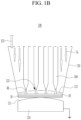
- FIGS. 1A and 1B are diagrams illustrating a schematic configuration of an arc welding device for a secondary battery according to an exemplary embodiment of the present invention.
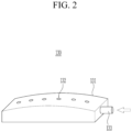
- FIG. 2 is an enlarged view showing a configuration of a lower fixing portion in FIGS. 1A and 1B .
- an arc welding device 100 for a secondary battery is a welding device 100 for bonding a plurality of electrode tabs 10 and an electrode lead 20 connected to an electrode of an electrode assembly and includes an upper fixing portion 120 and a lower fixing portion 130 disposed with the electrode tab 10 and the electrode lead 20 interposed therebetween.
- the arc welding device 100 for a secondary battery is a device for arc welding, not a configuration for ultrasonic welding or laser welding used for bonding the electrode tab 10 and the electrode lead 20 in the related art.
- arc welding also called gas tungsten arc welding
- inert gas such as Ar or He is used as a protective gas
- the arc welding is also called tungsten inert gas welding.
- the arc welding device 100 for a secondary battery allows this arc welding method to be applied to a welding method for bonding the electrode tab 10 and the electrode lead 20 to prevent an occurrence of spatter and foreign matter and damage to a battery.
- the upper fixing portion 120 includes a plurality of welding electrode units 200 connected to one pole of a welding power (not shown) therein.
- the welding electrode unit 200 may be a tungsten electrode, and may be disposed inside the upper fixing portion 120 such that an end thereof communicates with the outside through an arc hole 122 formed in the first facing surface 121 of the upper fixing portion 120. Power may be supplied through the welding electrode unit 200 to generate an arc AR.
- the tungsten electrode constituting the welding electrode unit 200 may include zirconia-based or lanthanide-based tungsten, but is not particularly limited.
- a first facing surface 121 formed to be concave toward an object to be welded, that is, the electrode lead 20 and the electrode tab 10, may be formed below the upper fixing portion 120.
- the first facing surface 121 may be in close contact with a second facing surface 131 of the lower fixing portion 130, which will be described later, to reliably fix the electrode lead 20 and the electrode tab 10, which are to be welded, during welding and minimize a gap therebetween.
- the upper fixing portion 120 may be formed in a chamber shape in which the welding electrode unit 200 is disposed, and the upper fixing portion 120 may further include a first nozzle portion 123 for supplying an inert gas IG at an upper portion thereof.
- the inert gas IG is supplied through the first nozzle portion 123 and passes through the inside of the upper fixing portion 120 to act as a shielding gas during welding through the arc hole 122 described above.
- the shielding gas a single or mixed gas selected from Ar, He, N 2 , etc. may be used, but is not particularly limited.
- As the inert gas IG is supplied to a welding portion during welding through the upper fixing portion 120, contact of the welding portion with oxygen may be blocked. In an exemplary embodiment of the present invention, such a structure may be simply provided through the upper fixing portion 120.
- the upper fixing portion 120 may include one or more materials selected from copper, a copper-based alloy, ceramic, and quartz. Accordingly, even if heat generated by the arc increases during arc welding, cooling may be performed quickly to enable repeated work, and since the material has heat resistance, it may be appropriately applied to arc welding.
- the lower fixing portion 130 connected to the other pole of the welding power with the object to be welded interposed therebetween is disposed below the upper fixing portion 120.
- the lower fixing portion 130 includes a second facing surface 131 facing the first facing surface 121 and formed to be convex to correspond to the concave shape of the first facing surface 121.
- An arrangement direction of the electrode tab 10 and the electrode lead 20 is not particularly limited. That is, as shown in FIG. 1A , the electrode tab 10 and the electrode lead 20 may be arranged such that convex shapes thereof correspond to each other in a length direction, or, as shown in FIG.
- the electrode tab 10 and the electrode lead 20 may be arranged in a width direction.
- additional shaping may be performed to have an appropriate shape by a subsequent pressing process, etc., and thus, such bending may not affect weld quality or performance of a final product.
- the electrode tab 10 and the electrode lead 20 to be welded may be disposed on the second facing surface 131, the first facing surface 121 of the upper fixing portion 120 may be brought into close contact with the second facing surface 131 to perform arc welding, and accordingly, a gap between the electrode tab 10 and the electrode lead 20 may be minimized and the electrode tab 10 and the electrode lead 20 may be stably supported during welding, whereby arc welding may be easily applied to the electrode tab 10 and the electrode lead 20 as well.
- a plurality of gas supply holes 132 may be further formed on the second facing surface 131.
- a second nozzle portion 133 communicating with the inside of the lower fixing portion 130 may be further provided to supply inert gas therethrough.
- the inert gas may be supplied through the gas supply hole 132 to further improve adhesion between the objects to be welded and block contact thereof with oxygen during welding.
- the lower fixing portion 130 may include copper or a copper-based alloy having good thermal conductivity. Thereby, rapid cooling may be achieved, but the present technology is not limited thereto.
- the welding device 100 for a secondary battery when used, arc welding that does not cause spatter may be applied in the bonding of the electrode tab 10 and the electrode lead 20 of the secondary battery, and as a result, the welding device may be simplified without adding an additional device (such as a suction device) for removing spatter, and a secondary battery may be manufactured without causing short circuit defects due to spatter.
- a suction device such as a suction device
- the welding electrode unit is included in the upper fixing portion, the upper fixing portion may serve as a fixing jig by itself together with the lower fixing portion, and the inert gas IG may also be easily supplied through the upper fixing portion, and therefore, costs for configuring the corresponding facility may be low to reduce overall equipment investment costs and suppress the occurrence of defects, thereby significantly improving the process efficiency.
- a plurality of electrode tabs connected to the respective electrodes and protruding outward and the electrode leads are aligned and disposed on the upper fixing portion 120 and the lower fixing portion 130. Thereafter, the first facing surface 121 of the upper fixing portion 120 and the second facing surface 131 of the lower fixing portion 130 are brought into close contact with each other with the electrode tab 10 and the electrode lead 20 interposed therebetween.
- the first facing surface 121 has a concave shape and the second facing surface 131 has a convex shape to correspond thereto, adhesion between the electrode lead 20 and the electrode tab 10 disposed therebetween may be improved and the electrode lead 20 and the electrode tab 10 may be fixed more stably.
- arc AR between the welding electrode unit 200 and the lower fixing portion 130
- welding i.e., gas tungsten arc welding (GTAW)
- GTAW gas tungsten arc welding
- the supplied power may have a base current in a range of 2 A to 4 A, and a peak current may be in a range of 4 A to 10 A. If the current value is smaller than this range, welding may not be sufficiently performed, and if the current value is larger, damage to the electrode lead 20 and the electrode tab 10 may occur. In particular, in the exemplary embodiment of the present invention, by supplying a relatively small base current and at the same time supplying a larger peak current, sufficient welding may be performed, without damage to the electrode lead 20 and the electrode tab 10.
- GTAW may be performed as pulse welding having a frequency of 2000 Hz or higher. Accordingly, welding may be performed without damage to the electrode lead 20 and the electrode tab 10.
- arc welding may be applied to a welding process for bonding the electrode tab 10 and the electrode lead 20 during the manufacture of a secondary battery, so that welding with high reliability may be performed even with simple facility, without causing spatter, thereby reducing a defect rate during manufacturing and reduce the process cost.
Landscapes
- Engineering & Computer Science (AREA)
- Physics & Mathematics (AREA)
- Plasma & Fusion (AREA)
- Mechanical Engineering (AREA)
- Chemical & Material Sciences (AREA)
- Chemical Kinetics & Catalysis (AREA)
- Electrochemistry (AREA)
- General Chemical & Material Sciences (AREA)
- Connection Of Batteries Or Terminals (AREA)
Abstract
Description
- The present application claims priority from
Korean Patent Application No. 10-2021-0022437 filed on February 19, 2021 - The present disclosure relates to an arc welding device for a secondary battery and a welding method using the same, and more particularly, to a welding device and method for applying arc welding in the case of welding an electrode tab and an electrode lead of a secondary battery.
- Recently, an increase in the price of an energy source and an interest in environmental pollution due to the depletion of fossil fuels have increased, demand for an eco-friendly alternative energy source has become an indispensable factor for future life. Accordingly, research on various power production technologies such as nuclear power, solar power, wind power, and tidal power has continued and power storage devices for using the produced energy more efficiently have been focused.
- In particular, as technology development and demand for mobile devices has increased, demand for batteries as an energy source has rapidly increased, and accordingly, a lot of research on batteries that may meet various needs has been conducted.
- Typically, there is high demand for lithium secondary batteries, such as lithium ion batteries and lithium ion polymer batteries, which have advantages such as high energy density, discharge voltage, and output stability.
- Secondary batteries may also be classified according to the structure of an electrode assembly in which a positive electrode, a negative electrode, and a separator interposed between the positive and negative electrodes are stacked. Typically, a jelly roll-type electrode assembly having a structure in which long sheet-shaped positive and negative electrodes are wound with a separator interposed therebetween, a stack-type electrode assembly in which a plurality of positive and negative electrodes cut into units having a predetermined size are sequentially stacked with a separator interposed therebetween, and the like may be listed. Recently, in order to solve the problems of the jelly roll-type electrode assembly and the stack-type electrode assembly, a stack/folding-type electrode assembly having a structure in which unit cells with positive and negative electrodes of a predetermined unit stacked with a separator interposed therebetween are located on a separation film and sequentially wound, as a mixed type of the jelly roll type and the stack type, has been developed.
- In addition, depending on a shape of a case, secondary batteries may be classified into a cylindrical secondary battery in which an electrode assembly is built in a cylindrical case, a prismatic secondary battery in which an electrode assembly is built in a prismatic case, and a pouch-type secondary battery in which an electrode assembly is built in a pouch-type case of a laminate sheet.
- In the case of the widely used pouch-type secondary batteries, an electrode assembly in which a positive electrode, a negative electrode, and a separator disposed therebetween are stacked is accommodated in a pouch-type case. Here, the plurality of electrode tabs connected to the respective electrodes are connected to an electrode lead by welding and electrically connected to an external component through an electrode lead exposed to the outside.
- When the electrode tab and the electrode lead are bonded, a welding method, specifically, an ultrasonic welding method and a laser welding method are generally used. However, in the case of ultrasonic welding applied here, fine metal foreign matter may occur due to friction with an oxide film during a welding process, and when the corresponding foreign matter is attached to a secondary battery, a short circuit defect may occur. In addition, even in the case of laser welding, which is widely used recently to avoid the disadvantages of ultrasonic welding, there is a problem of short-circuit failure due to spatter occurring during welding, and frequent replacement of jig or nozzle is required as these spatters are accumulated.
- An object of an exemplary embodiment of the present invention is to provide an arc welding device for a secondary battery and a welding method using the same, which may increase welding reliability, while reducing welding cost, without the occurrence of spatter in the case of welding an electrode tab and an electrode lead of a secondary battery.
- The problem to be solved by the present disclosure is not limited to the aforementioned problems, and the problems not mentioned will be clearly understood by those of ordinary skill in the art to which the present disclosure pertains from the present specification and the accompanying drawings.
- An arc welding device for a secondary battery according to an exemplary embodiment of the present invention includes an upper fixing portion in which a plurality of welding electrode units connected to one pole of a welding power are disposed and a lower fixing portion disposed to face the upper fixing portion with an object to be welded therebetween and connected to the other pole of the welding power, wherein the upper fixing portion includes a first facing surface facing the object to be welded and formed to be concave toward the object to be welded, the lower fixing portion includes a second facing surface facing the first facing face and formed to be convex to correspond to the concave shape of the first facing surface.
- An arc may be generated between the plurality of welding electrode units and the lower fixing portion by the supply of the welding power.
- The first facing surface may include a plurality of arc holes corresponding to the plurality of welding electrode units.
- The arc welding device may further include a first nozzle portion supplying an inert gas to an inside of the upper fixing portion.
- A plurality of gas supply holes may be formed in the second facing surface of the lower fixing portion, and the arc welding device may further include a second nozzle portion supplying an inert gas to an inside of the lower fixing portion.
- The object to be welded may be an electrode tab and an electrode lead of the secondary battery.
- The upper fixing portion may include one or more materials selected from copper, a copper-based alloy, ceramic, and quartz.
- The plurality of welding electrode units may include a plurality of tungsten electrodes.
- A welding method according to another exemplary embodiment of the present invention, as a welding method using the aforementioned arc welding device for a secondary battery, includes: preparing an electrode assembly including a plurality of electrode tabs protruding to the outside, disposing the electrode tab and the electrode lead between the upper fixing portion and the lower fixing portion, adhering the first facing surface and the second facing surface to each other with the electrode tab and the electrode lead interposed therebetween, and generating an arc between the welding electrode unit and the lower fixing portion to perform gas tungsten arc welding (GTAW).
- In the performing of the GTAW, a range of a base current supplied to the plurality of welding electrode units may be 2 A to 4 A, and a range of a peak current may be 4 A to 10 A.
- The GTAW may be performed as pulse welding having a frequency of 2000 Hz or higher.
- According to the exemplary embodiments, the arc welding device for a secondary battery and the welding method using the same, which may increase welding reliability, while reducing welding costs, without causing spatter, when welding an electrode tab and an electrode lead of a secondary battery.
- Aspects of the present invention are not limited to the aforementioned disclosure, and aspects not mentioned will be clearly understood by those of ordinary skill in the art to which the present disclosure pertains from the present specification and accompanying drawings.
-
-
FIGS. 1A and1B are diagrams illustrating a schematic configuration of an arc welding device for a secondary battery according to an exemplary embodiment of the present invention. -
FIG. 2 is an enlarged view showing a configuration of a lower fixing portion inFIGS. 1A and1B . - Hereinafter, exemplary embodiments of the present invention will be described in detail with reference to the accompanying drawings to allow those skilled in the art to practice the present technology. Exemplary embodiments of the present invention may be implemented in various different forms and is not limited to the examples as described herein.
- Portions unrelated to the description may be omitted in order to more clearly describe exemplary embodiments of the present invention, and the same or similar components may be denoted by the same reference numerals throughout the present specification.
- Further, the size and thickness of each component shown in the drawings may be arbitrarily shown for convenience of explanation, and therefore, the present technology is not necessarily limited to the shown exemplary embodiments in the drawings. In the drawings, the thickness of various layers, regions, etc., may be exaggerated for clarity. In the drawings, the thickness of partial layers and regions may be exaggerated for convenience of explanation.
- In addition, unless explicitly described to the contrary, the word "comprise", and variations such as "comprises" or "comprising", will be understood to imply the inclusion of stated elements but not the exclusion of any other elements.
- Throughout the specification, when it is referred to "in plan view", it means that a target element is viewed from above, and when it is referred to "in crosssectional view", it means that a target element taken vertically is viewed from the side.
- Hereinafter, a welding device for a secondary battery and a welding method using the same according to an exemplary embodiment of the present invention will be described with reference to
FIGS. 1A ,1B , and2 . -
FIGS. 1A and1B are diagrams illustrating a schematic configuration of an arc welding device for a secondary battery according to an exemplary embodiment of the present invention.FIG. 2 is an enlarged view showing a configuration of a lower fixing portion inFIGS. 1A and1B . - Referring to
FIGS. 1A and1B and2 , anarc welding device 100 for a secondary battery according to an exemplary embodiment of the present invention is awelding device 100 for bonding a plurality ofelectrode tabs 10 and anelectrode lead 20 connected to an electrode of an electrode assembly and includes anupper fixing portion 120 and alower fixing portion 130 disposed with theelectrode tab 10 and theelectrode lead 20 interposed therebetween. - In particular, the
arc welding device 100 for a secondary battery is a device for arc welding, not a configuration for ultrasonic welding or laser welding used for bonding theelectrode tab 10 and theelectrode lead 20 in the related art. In general, arc welding, also called gas tungsten arc welding, is a welding method in which a base material is melted and joined by arc heat generated using a tungsten electrode. Here, since inert gas such as Ar or He is used as a protective gas, the arc welding is also called tungsten inert gas welding. - The
arc welding device 100 for a secondary battery according to an exemplary embodiment of the present invention allows this arc welding method to be applied to a welding method for bonding theelectrode tab 10 and theelectrode lead 20 to prevent an occurrence of spatter and foreign matter and damage to a battery. - The
upper fixing portion 120 includes a plurality ofwelding electrode units 200 connected to one pole of a welding power (not shown) therein. Thewelding electrode unit 200 may be a tungsten electrode, and may be disposed inside theupper fixing portion 120 such that an end thereof communicates with the outside through anarc hole 122 formed in the first facingsurface 121 of theupper fixing portion 120. Power may be supplied through thewelding electrode unit 200 to generate an arc AR. The tungsten electrode constituting thewelding electrode unit 200 may include zirconia-based or lanthanide-based tungsten, but is not particularly limited. - A first facing
surface 121 formed to be concave toward an object to be welded, that is, theelectrode lead 20 and theelectrode tab 10, may be formed below theupper fixing portion 120. The first facingsurface 121 may be in close contact with a second facingsurface 131 of thelower fixing portion 130, which will be described later, to reliably fix theelectrode lead 20 and theelectrode tab 10, which are to be welded, during welding and minimize a gap therebetween. - In addition, the
upper fixing portion 120 may be formed in a chamber shape in which thewelding electrode unit 200 is disposed, and theupper fixing portion 120 may further include afirst nozzle portion 123 for supplying an inert gas IG at an upper portion thereof. The inert gas IG is supplied through thefirst nozzle portion 123 and passes through the inside of theupper fixing portion 120 to act as a shielding gas during welding through thearc hole 122 described above. As the shielding gas, a single or mixed gas selected from Ar, He, N2, etc. may be used, but is not particularly limited. As the inert gas IG is supplied to a welding portion during welding through theupper fixing portion 120, contact of the welding portion with oxygen may be blocked. In an exemplary embodiment of the present invention, such a structure may be simply provided through theupper fixing portion 120. - The
upper fixing portion 120 may include one or more materials selected from copper, a copper-based alloy, ceramic, and quartz. Accordingly, even if heat generated by the arc increases during arc welding, cooling may be performed quickly to enable repeated work, and since the material has heat resistance, it may be appropriately applied to arc welding. - The
lower fixing portion 130 connected to the other pole of the welding power with the object to be welded interposed therebetween is disposed below theupper fixing portion 120. Thelower fixing portion 130 includes a second facingsurface 131 facing the first facingsurface 121 and formed to be convex to correspond to the concave shape of the first facingsurface 121. On the second facingsurface 131, theelectrode tab 10 and theelectrode lead 20 to be welded are disposed. An arrangement direction of theelectrode tab 10 and theelectrode lead 20 is not particularly limited. That is, as shown inFIG. 1A , theelectrode tab 10 and theelectrode lead 20 may be arranged such that convex shapes thereof correspond to each other in a length direction, or, as shown inFIG. 1B , theelectrode tab 10 and theelectrode lead 20 may be arranged in a width direction. In addition, even if the shape of each of theelectrode tab 10 and theelectrode lead 20 is bent to correspond to a shape of a contact surface of the fixingportions - The
electrode tab 10 and theelectrode lead 20 to be welded may be disposed on the second facingsurface 131, the first facingsurface 121 of theupper fixing portion 120 may be brought into close contact with the second facingsurface 131 to perform arc welding, and accordingly, a gap between theelectrode tab 10 and theelectrode lead 20 may be minimized and theelectrode tab 10 and theelectrode lead 20 may be stably supported during welding, whereby arc welding may be easily applied to theelectrode tab 10 and theelectrode lead 20 as well. - Meanwhile, as shown in
FIG. 2 , a plurality of gas supply holes 132 may be further formed on the second facingsurface 131. In addition, asecond nozzle portion 133 communicating with the inside of thelower fixing portion 130 may be further provided to supply inert gas therethrough. The inert gas may be supplied through thegas supply hole 132 to further improve adhesion between the objects to be welded and block contact thereof with oxygen during welding. - The
lower fixing portion 130 may include copper or a copper-based alloy having good thermal conductivity. Thereby, rapid cooling may be achieved, but the present technology is not limited thereto. - As described above, when the
welding device 100 for a secondary battery according to an exemplary embodiment of the present invention is used, arc welding that does not cause spatter may be applied in the bonding of theelectrode tab 10 and theelectrode lead 20 of the secondary battery, and as a result, the welding device may be simplified without adding an additional device (such as a suction device) for removing spatter, and a secondary battery may be manufactured without causing short circuit defects due to spatter. In addition, the welding electrode unit is included in the upper fixing portion, the upper fixing portion may serve as a fixing jig by itself together with the lower fixing portion, and the inert gas IG may also be easily supplied through the upper fixing portion, and therefore, costs for configuring the corresponding facility may be low to reduce overall equipment investment costs and suppress the occurrence of defects, thereby significantly improving the process efficiency. - Meanwhile, in another exemplary embodiment of the present invention, there is provided a welding method using the aforementioned welding device for a secondary battery.
- That is, in the electrode assembly in which a positive electrode, a negative electrode, and a separator disposed between the positive electrode and the negative electrode are stacked, a plurality of electrode tabs connected to the respective electrodes and protruding outward and the electrode leads are aligned and disposed on the
upper fixing portion 120 and thelower fixing portion 130. Thereafter, the first facingsurface 121 of theupper fixing portion 120 and the second facingsurface 131 of thelower fixing portion 130 are brought into close contact with each other with theelectrode tab 10 and theelectrode lead 20 interposed therebetween. - At this time, as described above, since the first facing
surface 121 has a concave shape and the second facingsurface 131 has a convex shape to correspond thereto, adhesion between theelectrode lead 20 and theelectrode tab 10 disposed therebetween may be improved and theelectrode lead 20 and theelectrode tab 10 may be fixed more stably. - Subsequently, power is supplied to generate an arc AR between the
welding electrode unit 200 and thelower fixing portion 130, and welding (i.e., gas tungsten arc welding (GTAW)) is performed by the generated arc AR. That is, in a state in which theupper fixing portion 120 is in close contact with theelectrode lead 20 and theelectrode tab 10, thewelding electrode unit 200 is close to the object to be welded, and in this state, power is supplied to generate the arc AR so that a base material may be melted and welding is performed. - At this time, the supplied power may have a base current in a range of 2 A to 4 A, and a peak current may be in a range of 4 A to 10 A. If the current value is smaller than this range, welding may not be sufficiently performed, and if the current value is larger, damage to the
electrode lead 20 and theelectrode tab 10 may occur. In particular, in the exemplary embodiment of the present invention, by supplying a relatively small base current and at the same time supplying a larger peak current, sufficient welding may be performed, without damage to theelectrode lead 20 and theelectrode tab 10. - In addition, GTAW may be performed as pulse welding having a frequency of 2000 Hz or higher. Accordingly, welding may be performed without damage to the
electrode lead 20 and theelectrode tab 10. - As described above, according to the exemplary embodiments of the present invention, arc welding may be applied to a welding process for bonding the
electrode tab 10 and theelectrode lead 20 during the manufacture of a secondary battery, so that welding with high reliability may be performed even with simple facility, without causing spatter, thereby reducing a defect rate during manufacturing and reduce the process cost. - While the present disclosure has been described in connection with exemplary embodiments, it is to be understood that the technology is not limited to the disclosed exemplary embodiments, but, on the contrary, is intended to cover various modifications and equivalent arrangements included within the spirit and scope of the appended claims.
-
- 100: arc welding device for a secondary battery
- 200: welding electrode unit
- 120: upper fixing portion
- 130: lower fixing portion
- 121: first facing surface
- 131: second facing surface
- 10: electrode tab
- 20: electrode lead
Claims (11)
- An arc welding device for a secondary battery, the arc welding device comprising:an upper fixing portion, the upper fixing portion including a plurality of welding electrode units, the plurality of welding electrode units being connected to a first pole of a welding power; anda lower fixing portion disposed to face the upper fixing portion, wherein the lower facing portion is connected to a second pole of the welding power, wherein an object to be welded is configured to be disposed between the upper fixing portion and the lower fixing portion;wherein the upper fixing portion includes a first facing surface, the first facing surface being concave and the first facing surface being configured to face the object to be welded, andwherein the lower fixing portion includes a second facing surface, the second facing surface being convex, the convex second facing surface being configured to correspond to the concave shape of the first facing surface and the second facing surface being configured to face the first facing surface.
- The arc welding device of claim 1, wherein:
the arc welding device is configured to generate an arc between the plurality of welding electrode units and the lower fixing portion by supplying welding power. - The arc welding device of claim 1, wherein:
the first facing surface includes a plurality of arc holes, the plurality of arc holes being configured to correspond to a position of the plurality of welding electrode units, wherein the plurality of arc holes are configured to allow passage of the arc. - The arc welding device of claim 1, further comprising:
a first nozzle unit configured to supply an inert gas to an interior of the upper fixing portion. - The arc welding device of claim 1, wherein:a plurality of gas supply holes are disposed in the second facing surface of the lower fixing portion,wherein the arc welding device further comprises a second nozzle unit configured to supply an inert gas to an interior of the lower fixing portion.
- The arc welding device of claim 1, wherein:
the object to be welded includes an electrode tab and an electrode lead. - The arc welding device of claim 1, wherein:
the upper fixing portion includes one or more of copper, a copper-based alloy, ceramic, or quartz. - The arc welding device of claim 1, wherein:
the plurality of welding electrode units includes a plurality of tungsten electrodes. - A welding method using the arc welding device of claim 1, the welding method comprising:preparing an electrode assembly including a plurality of electrode tabs,disposing the plurality of electrode tabs and an electrode lead between the upper fixing portion and the lower fixing portion;positioning the first facing surface of the upper fixing portion and the second facing surface of the lower facing portion to face each other, wherein the plurality of electrode tabs and the electrode lead are interposed therebetween; andgenerating an arc between the plurality of welding electrode units and the lower fixing portion to perform gas tungsten arc welding.
- The welding method of claim 9, wherein:
in the performing of the gas tungsten arc welding, a range of a base current supplied to the plurality of welding electrode units is from 2 A to 4 A, and a range of a peak current is from 4 A to 10 A. - The welding method of claim 10, wherein:
the gas tungsten arc welding is performed as pulse welding having a frequency of 2000 Hz or higher.
Applications Claiming Priority (2)
| Application Number | Priority Date | Filing Date | Title |
|---|---|---|---|
| KR1020210022437A KR20220118699A (en) | 2021-02-19 | 2021-02-19 | Arc welding device for secondary battery, and welding method using the same |
| PCT/KR2022/002288 WO2022177289A1 (en) | 2021-02-19 | 2022-02-16 | Arc welding device for secondary battery, and welding method using same |
Publications (2)
| Publication Number | Publication Date |
|---|---|
| EP4249157A1 true EP4249157A1 (en) | 2023-09-27 |
| EP4249157A4 EP4249157A4 (en) | 2024-05-22 |
Family
ID=82930946
Family Applications (1)
| Application Number | Title | Priority Date | Filing Date |
|---|---|---|---|
| EP22756487.9A Pending EP4249157A4 (en) | 2021-02-19 | 2022-02-16 | Arc welding device for secondary battery, and welding method using same |
Country Status (5)
| Country | Link |
|---|---|
| US (1) | US20240139850A1 (en) |
| EP (1) | EP4249157A4 (en) |
| KR (1) | KR20220118699A (en) |
| CN (1) | CN116745057A (en) |
| WO (1) | WO2022177289A1 (en) |
Citations (4)
| Publication number | Priority date | Publication date | Assignee | Title |
|---|---|---|---|---|
| US3641309A (en) * | 1969-08-27 | 1972-02-08 | Kabel Metallwerke Ghh | Apparatus for welding thin metal sheets |
| US4341944A (en) * | 1977-12-21 | 1982-07-27 | Alcan Research And Development Limited | Reduction of arc blow in multi-electrode welding |
| US20110117420A1 (en) * | 2009-11-19 | 2011-05-19 | Sung-Bae Kim | Bus bar and battery module including the same |
| KR101418899B1 (en) * | 2012-12-27 | 2014-07-14 | 아마다미야찌코리아 주식회사 | Method for jointing metal foils in a superposed way and joint structure |
Family Cites Families (5)
| Publication number | Priority date | Publication date | Assignee | Title |
|---|---|---|---|---|
| JPH0688132B2 (en) * | 1989-06-06 | 1994-11-09 | スカイアルミニウム株式会社 | Lap welding of thin plates |
| JP2007061830A (en) * | 2005-08-29 | 2007-03-15 | Toyota Auto Body Co Ltd | Welding apparatus |
| KR20130042954A (en) * | 2011-10-19 | 2013-04-29 | 주식회사 엘지화학 | Secondary battery having improved safety characteristics and manufacturing method thereof |
| CN106141387A (en) * | 2016-08-24 | 2016-11-23 | 江苏阿斯美特精工科技有限公司 | Coaxial hollow tungsten electrode heating wire TIG welding gun, welder and welding method |
| KR102178729B1 (en) * | 2017-12-26 | 2020-11-13 | 주식회사 포스코 | Method for welding steel material |
-
2021
- 2021-02-19 KR KR1020210022437A patent/KR20220118699A/en active Search and Examination
-
2022
- 2022-02-16 CN CN202280008488.5A patent/CN116745057A/en active Pending
- 2022-02-16 EP EP22756487.9A patent/EP4249157A4/en active Pending
- 2022-02-16 US US18/272,139 patent/US20240139850A1/en active Pending
- 2022-02-16 WO PCT/KR2022/002288 patent/WO2022177289A1/en active Application Filing
Patent Citations (4)
| Publication number | Priority date | Publication date | Assignee | Title |
|---|---|---|---|---|
| US3641309A (en) * | 1969-08-27 | 1972-02-08 | Kabel Metallwerke Ghh | Apparatus for welding thin metal sheets |
| US4341944A (en) * | 1977-12-21 | 1982-07-27 | Alcan Research And Development Limited | Reduction of arc blow in multi-electrode welding |
| US20110117420A1 (en) * | 2009-11-19 | 2011-05-19 | Sung-Bae Kim | Bus bar and battery module including the same |
| KR101418899B1 (en) * | 2012-12-27 | 2014-07-14 | 아마다미야찌코리아 주식회사 | Method for jointing metal foils in a superposed way and joint structure |
Non-Patent Citations (1)
| Title |
|---|
| See also references of WO2022177289A1 * |
Also Published As
| Publication number | Publication date |
|---|---|
| US20240139850A1 (en) | 2024-05-02 |
| WO2022177289A1 (en) | 2022-08-25 |
| CN116745057A (en) | 2023-09-12 |
| EP4249157A4 (en) | 2024-05-22 |
| KR20220118699A (en) | 2022-08-26 |
Similar Documents
| Publication | Publication Date | Title |
|---|---|---|
| JP5044108B2 (en) | Battery connection device | |
| KR102366429B1 (en) | Electrodes with Improved Welding Characteristics of Electrode Tabs and Secondary Battery Using the same | |
| WO2008013371A1 (en) | Electrode assembly having electrode tabs of the same size in joint portion thereof and electrochemical cell containing the same | |
| WO2007004335A1 (en) | Inter-battery connection device | |
| JP6698869B2 (en) | Battery pack with electrode terminal connection plate | |
| US10749204B2 (en) | Electric power storage device and method of manufacturing the same | |
| US9979009B2 (en) | Energy storage device having a laser weld | |
| JP6650326B2 (en) | Battery pack and method of manufacturing battery pack | |
| KR101222284B1 (en) | Battery and method for producing the same | |
| KR20110058658A (en) | Rechargeable battery | |
| KR102157495B1 (en) | Pouch type battery cell and manufacturing method thereof | |
| JP3221324B2 (en) | Thin battery and manufacturing method thereof | |
| JP2004241150A (en) | Battery | |
| US8574756B1 (en) | Prismatic secondary battery | |
| EP4249157A1 (en) | Arc welding device for secondary battery, and welding method using same | |
| KR20130129837A (en) | Method for treating surface of electrode by laser irradiation | |
| KR101124964B1 (en) | Method for connecting between cathod lead or anode lead of secondary battery and external element | |
| KR101678810B1 (en) | Apparatus Comprising Jig Having Hole for Alignment of Welding Rods | |
| CN115398729A (en) | Battery pack having circuit board and electrode lead directly joined to each other by laser welding | |
| KR20210034963A (en) | Method for manufacturing cylindrical secondary battery | |
| KR101310441B1 (en) | Electrochemical capacitor | |
| KR100435038B1 (en) | Method for forming cathode terminal of Lithium ion secondary battery | |
| KR102697802B1 (en) | Method For Welding Electrode Tabs | |
| CN219832960U (en) | Battery and battery pack | |
| CN219759895U (en) | Battery and battery pack |
Legal Events
| Date | Code | Title | Description |
|---|---|---|---|
| STAA | Information on the status of an ep patent application or granted ep patent |
Free format text: STATUS: THE INTERNATIONAL PUBLICATION HAS BEEN MADE |
|
| PUAI | Public reference made under article 153(3) epc to a published international application that has entered the european phase |
Free format text: ORIGINAL CODE: 0009012 |
|
| STAA | Information on the status of an ep patent application or granted ep patent |
Free format text: STATUS: REQUEST FOR EXAMINATION WAS MADE |
|
| 17P | Request for examination filed |
Effective date: 20230620 |
|
| AK | Designated contracting states |
Kind code of ref document: A1 Designated state(s): AL AT BE BG CH CY CZ DE DK EE ES FI FR GB GR HR HU IE IS IT LI LT LU LV MC MK MT NL NO PL PT RO RS SE SI SK SM TR |
|
| A4 | Supplementary search report drawn up and despatched |
Effective date: 20240422 |
|
| RIC1 | Information provided on ipc code assigned before grant |
Ipc: B23K 101/38 20060101ALI20240416BHEP Ipc: B23K 9/167 20060101ALI20240416BHEP Ipc: B23K 9/035 20060101ALI20240416BHEP Ipc: B23K 9/00 20060101ALI20240416BHEP Ipc: B23K 101/18 20060101ALI20240416BHEP Ipc: B23K 101/36 20060101ALI20240416BHEP Ipc: B23K 9/09 20060101ALI20240416BHEP Ipc: B23K 9/16 20060101ALI20240416BHEP Ipc: B23K 9/10 20060101AFI20240416BHEP |
|
| DAV | Request for validation of the european patent (deleted) | ||
| DAX | Request for extension of the european patent (deleted) |