EP4249134A1 - Coating gasket and coating device - Google Patents
Coating gasket and coating device Download PDFInfo
- Publication number
- EP4249134A1 EP4249134A1 EP22848056.2A EP22848056A EP4249134A1 EP 4249134 A1 EP4249134 A1 EP 4249134A1 EP 22848056 A EP22848056 A EP 22848056A EP 4249134 A1 EP4249134 A1 EP 4249134A1
- Authority
- EP
- European Patent Office
- Prior art keywords
- gasket
- slurry
- coating
- flow channel
- outlet
- Prior art date
- Legal status (The legal status is an assumption and is not a legal conclusion. Google has not performed a legal analysis and makes no representation as to the accuracy of the status listed.)
- Granted
Links
Images


Classifications
-
- B—PERFORMING OPERATIONS; TRANSPORTING
- B05—SPRAYING OR ATOMISING IN GENERAL; APPLYING FLUENT MATERIALS TO SURFACES, IN GENERAL
- B05C—APPARATUS FOR APPLYING FLUENT MATERIALS TO SURFACES, IN GENERAL
- B05C5/00—Apparatus in which liquid or other fluent material is projected, poured or allowed to flow on to the surface of the work
- B05C5/02—Apparatus in which liquid or other fluent material is projected, poured or allowed to flow on to the surface of the work the liquid or other fluent material being discharged through an outlet orifice by pressure, e.g. from an outlet device in contact or almost in contact, with the work
- B05C5/0254—Coating heads with slot-shaped outlet
-
- B—PERFORMING OPERATIONS; TRANSPORTING
- B05—SPRAYING OR ATOMISING IN GENERAL; APPLYING FLUENT MATERIALS TO SURFACES, IN GENERAL
- B05C—APPARATUS FOR APPLYING FLUENT MATERIALS TO SURFACES, IN GENERAL
- B05C9/00—Apparatus or plant for applying liquid or other fluent material to surfaces by means not covered by any preceding group, or in which the means of applying the liquid or other fluent material is not important
- B05C9/06—Apparatus or plant for applying liquid or other fluent material to surfaces by means not covered by any preceding group, or in which the means of applying the liquid or other fluent material is not important for applying two different liquids or other fluent materials, or the same liquid or other fluent material twice, to the same side of the work
-
- H—ELECTRICITY
- H01—ELECTRIC ELEMENTS
- H01M—PROCESSES OR MEANS, e.g. BATTERIES, FOR THE DIRECT CONVERSION OF CHEMICAL ENERGY INTO ELECTRICAL ENERGY
- H01M10/00—Secondary cells; Manufacture thereof
- H01M10/04—Construction or manufacture in general
-
- H—ELECTRICITY
- H01—ELECTRIC ELEMENTS
- H01M—PROCESSES OR MEANS, e.g. BATTERIES, FOR THE DIRECT CONVERSION OF CHEMICAL ENERGY INTO ELECTRICAL ENERGY
- H01M4/00—Electrodes
- H01M4/02—Electrodes composed of, or comprising, active material
- H01M4/04—Processes of manufacture in general
-
- H—ELECTRICITY
- H01—ELECTRIC ELEMENTS
- H01M—PROCESSES OR MEANS, e.g. BATTERIES, FOR THE DIRECT CONVERSION OF CHEMICAL ENERGY INTO ELECTRICAL ENERGY
- H01M4/00—Electrodes
- H01M4/02—Electrodes composed of, or comprising, active material
- H01M4/04—Processes of manufacture in general
- H01M4/0402—Methods of deposition of the material
- H01M4/0409—Methods of deposition of the material by a doctor blade method, slip-casting or roller coating
-
- Y—GENERAL TAGGING OF NEW TECHNOLOGICAL DEVELOPMENTS; GENERAL TAGGING OF CROSS-SECTIONAL TECHNOLOGIES SPANNING OVER SEVERAL SECTIONS OF THE IPC; TECHNICAL SUBJECTS COVERED BY FORMER USPC CROSS-REFERENCE ART COLLECTIONS [XRACs] AND DIGESTS
- Y02—TECHNOLOGIES OR APPLICATIONS FOR MITIGATION OR ADAPTATION AGAINST CLIMATE CHANGE
- Y02E—REDUCTION OF GREENHOUSE GAS [GHG] EMISSIONS, RELATED TO ENERGY GENERATION, TRANSMISSION OR DISTRIBUTION
- Y02E60/00—Enabling technologies; Technologies with a potential or indirect contribution to GHG emissions mitigation
- Y02E60/10—Energy storage using batteries
Definitions
- the present application relates to the technical field of battery manufacturing, and in particular to a coating gasket and a coating device.
- the present application provides a coating gasket and a coating device, so as to form a clear boundary when an active material layer and an insulating layer are jointly coated on an electrode sheet of a battery.
- a first aspect of the present application provides a coating gasket for applying a first slurry and a second slurry to an object to be coated.
- the coating gasket includes: a first flow channel for applying the first slurry to the object to be coated to form a first coating layer; and a second flow channel for applying the second slurry to the object to be coated to form a second coating layer.
- the first flow channel has a first slurry outlet at a first end face of the gasket facing the object to be coated
- the second flow channel has a second slurry outlet at the first end face
- the first slurry outlet and the second slurry outlet are configured to partially overlap in a thickness direction of the gasket, such that the first coating layer and the second coating layer partially overlap in the thickness direction of the gasket.
- the first slurry outlet and the second slurry outlet partially overlap in the thickness direction of the gasket.
- the first coating layer partially covers the second coating layer, thereby reducing the problem of the unclear boundary between the first coating layer and the second coating layer at the adjacent position.
- the first slurry outlet is arranged spaced apart from the second slurry outlet.
- the first slurry and the second slurry can be fully layered, thereby reducing the possibility of the first slurry and the second slurry penetrating into and mixing with each other during coating, so that a well-defined boundary is formed between the first coating layer and the second coating layer.
- the height of the second slurry outlet in the thickness direction is less than the thickness of the gasket, so that the first slurry outlet can partially cover the second slurry outlet in the thickness direction of the gasket, thereby ensuring that the first slurry outlet partially overlaps with the second slurry outlet in the thickness direction of the gasket.
- the first slurry outlet and the second slurry outlet have an overlapping width of 0.1-9 mm in an arrangement direction of the first flow channel and the second flow channel.
- the overlapping width is set such that the first slurry outlet is lap jointed to the second slurry outlet, to enable an edge of the first coating layer to cover an edge of the second coating layer.
- the second flow channel comprises an opening portion extending to the second slurry outlet, the opening portion having a width in the arrangement direction of the first flow channel and the second flow channel that gradually increases in a direction from a slurry inlet of the second flow channel to the second slurry outlet.
- the width of the flow channel increases, but the flow rate of the second slurry remains unchanged, so that the depth of the second slurry in the opening portion in the thickness direction of the gasket becomes smaller, thereby making the second coating layer applied to the object to be coated thinner.
- the first flow channel has a side surface in the arrangement direction of the first flow channel and the second flow channel that comprises a slope portion and a step portion connected to each other, the slope portion partially overlapping with the second slurry outlet in the thickness direction of the gasket.
- the first slurry flowing out of the first flow channel through the slope portion is relatively thin, so that the coating thickness at the overlapping position of the first coating layer and the second coating layer will not be significantly increased to form a protrusion, and the overall thickness of the first coating layer thus remains uniform.
- the step portion has a height of 0.01-4.8 mm in the thickness direction of the gasket.
- the setting of the height of the step portion not only ensures that the slope portion partially overlaps with the second slurry outlet in the thickness direction of the gasket, but also ensures the structural strength of the coating gasket.
- the slope portion has a width in the arrangement direction of the first flow channel and the second flow channel that is not greater than 10 mm.
- the setting of the width of the slope portion can not only ensure that the slope portion fully covers the second slurry outlet, but can also ensure the width of the part of the second slurry outlet that is not covered by the slope portion, thereby ensuring that the first coating layer partially covers the second coating layer, and ensuring the width of the exposed part of the second coating layer.
- the slope portion has a length of 1-50 mm in an outflow direction of the first slurry.
- the length of the slope portion is set such that the slope portion covers, in a width direction, the edge of the second flow channel for a certain length, which can ensure that when flowing out, the first slurry covers the second slurry.
- the second flow channel comprises a groove portion for communicating the slurry inlet of the second flow channel and the second slurry outlet, and the slurry inlet penetrates the gasket in the thickness direction of the gasket.
- the slurry inlet is configured to penetrate the coating gasket, which can be applied to the situation where the second slurry flows into the coating gasket from an upper die or a lower die of the coating device, thereby increasing the application range of the coating gasket.
- the groove portion comprises an inlet section, an outlet section and a communication section; in the thickness direction of the gasket, the inlet section and the outlet section are respectively located on two sides of the gasket; and the inlet section is connected to the slurry inlet, the communication section is connected to the inlet section and the outlet section, and the outlet section is connected to the second slurry outlet.
- the flow channel of the second flow channel is adaptively shaped such that the coating gasket can adapt to different working conditions, thereby increasing the application range of the coating gasket.
- the gasket has a thickness of 0.2-5 mm, and the inlet section and the outlet section each have a depth of 5%-95% of the thickness of the gasket.
- the setting of the depth of the inlet section and the outlet section can make the second slurry flow out along the second flow channel, ensure the strength of the coating gasket, and ensure that the first slurry outlet and the second slurry outlet of the coating gasket partially overlap in the thickness direction of the gasket.
- a second aspect of the present application provides a coating device, including a lower die, an upper die, and the coating gasket as described above, the coating gasket being arranged between the upper die and the lower die.
- the first slurry outlet of the first flow channel and the second slurry outlet of the second flow channel partially overlap in the thickness direction of the gasket, so that the first coating layer and the second coating layer partially overlap in the thickness direction of the gasket.
- the first coating layer partially covers the second coating layer, thereby reducing the problem of the unclear boundary between the first coating layer and the second coating layer at the adjacent position.
- the applicant has found that when an existing coating device is used to jointly coat the active material layer and the insulating layer on a current collector of the electrode sheet of the battery, the active material layer and the insulating layer are likely to be mixed during a drying process, resulting in an unclear boundary position, which leads to deviation in the determination of the die-cutting position of the tab, and reduces the dimensional accuracy of the electrode sheet of the battery.
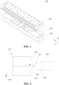
- Fig. 1 is an exploded structural schematic view of a coating device 100 according to an embodiment of the present application.
- the coating device 100 provided by the present application includes an upper die 200, a lower die 300, and a coating gasket 400 arranged between the upper die 200 and the lower die 300.
- Fig. 2 is a schematic view of an object 500 to be coated being coated by a coating device 100 according to an embodiment of the present application.
- an end face 101 of the coating device 100 perpendicular to a slurry outflow direction faces the object 500 to be coated, to perform a coating operation on the object 500 to be coated.
- the object 500 to be coated is transported on a drive roller 600, so that the object 500 to be coated is transported to the position of the end face 101 of the coating device 100, so as to realize continuous coating of the object 500 to be coated.
- the slurry outflow direction is defined as a width direction Y of the coating gasket 400, and the width direction Y mentioned herein is the slurry outflow direction.
- the coating device 100 can simultaneously apply two slurries to the object 500 to be coated, to form two different coatings.
- a first slurry is delivered from the lower die 300 to the coating gasket 400
- a second slurry is delivered from the upper die 200 or the lower die 300 to the coating gasket 400.
- the first slurry and the second slurry flow out, through outlets respectively provided on the coating gasket 400, to the end face 101 perpendicular to the width direction Y, and are applied to the object 500 to be coated.
- the second slurry may be delivered from the upper die 200 to the coating gasket 400, or from the lower die 300 to the coating gasket 400, which can be set according to the actual usage and the structure of the coating gasket 400.
- the object 500 to be coated is described in detail as a current collector of an electrode sheet of a battery.
- the present application is not limited to the coating of the current collector of the electrode sheet of the battery.
- the object 500 to be coated may be any carrier that needs to be coated with a coating.
- the first slurry may be an active material, which is applied to the current collector to form an active material layer; and the second slurry may be an insulating material, which is applied to the current collector to form an insulating layer.
- the current collector is a continuous foil, which is transported on the drive roller 600.
- a slurry flows out of a slurry outlet of the coating device 100 that is provided on the end face 101, and is applied to the current collector, such that a continuous coating layer is formed on the current collector.
- the current collector coated with the coating layer is die-cut according to the size of the electrode sheet of the battery, to obtain an electrode sheet of the battery of a predetermined size.
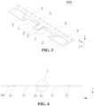
- Fig. 3 is a perspective structural schematic view of a coating gasket 400 according to an embodiment of the present application.
- a coating gasket 400 is used for applying a first slurry and a second slurry to an object 500 to be coated.
- the coating gasket 400 includes a first flow channel 1 and a second flow channel 2.
- the first flow channel 1 is used for applying the first slurry to the object 500 to be coated, to form a first coating layer
- the second flow channel 2 is used for applying the second slurry to the object 500 to be coated, to form a second coating layer.
- a plurality of mounting holes 3 are further provided in the coating gasket 400 for fixed connection with the upper die 200 and the lower die 300.
- Second flow channels 2 are respectively arranged on two sides of the first flow channel 1 of the coating gasket 400 in Fig. 3 .
- the respective arrangement of the second flow channels 2 on the two sides of the first flow channel 1 enables second coating layers to be coated to both sides of the first coating layer when the current collector is being coated.
- the current collector is die-cut in the middle of the first coating layer, so that two electrode sheets of the battery can be formed, each electrode sheet of the battery is coated with the first coating layer, and the edge of the first coating layer is coated with the second coating layer.
- two first flow channels 1 are arranged side-by-side on the coating gasket 400 in an arrangement direction of the first flow channels 1 and the second flow channels 2. In this way, it is possible to realize the coating of multiple electrode sheets of the battery for one current collector through one coating operation, improves the coating efficiency.
- first flow channels 1 are arranged side-by-side on the coating gasket 400, and second flow channels 2 are respectively arranged on two sides of each first flow channel 1, so that multiple electrode sheets of the battery are coated through one coating operation.
- the arrangement direction of the first flow channel 1 and the second flow channel 2 is defined as a length direction X of the coating gasket 400, and the length direction X mentioned herein is the arrangement direction of the first flow channel 1 and the second flow channel 2.
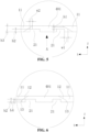
- Fig. 4 is a front view of a coating gasket 400 according to an embodiment of the present application.
- the coating gasket 400 has a first end face 401 on the side facing the object 500 to be coated.
- the first end face 401 is perpendicular to the width direction Y
- the first flow channel 1 has a first slurry outlet 11 at the first end face 401
- the second flow channel 2 has a second slurry outlet 21 at the first end face 401
- the first slurry outlet 11 and the second slurry outlet 21 are configured to have projections in a thickness direction Z of the gasket partially overlapping, so that projections of the first coating layer and the second coating layer partially overlap in the thickness direction Z of the gasket.
- the first slurry outlet 11 is partially located above the second slurry outlet 21.
- the first slurry flows out from the first slurry outlet 11
- the second slurry flows out from the second slurry outlet 21, such that the first slurry partially covers the second slurry, and the first slurry and the second slurry respectively form the first coating layer and the second coating layer applied to the foil of the current collector of the electrode sheet of the battery.
- the first coating layer partially covers the second coating layer, and during the drying process, the second slurry is prevented from penetrating towards the first slurry to an upper surface of the first coating layer, thereby avoiding the problem of the unclear boundary between the first coating layer and the second coating layer at the adjacent position.
- Fig. 5 is an enlarged view of part I of Fig. 4 .
- the projections of the first slurry outlet 11 and the second slurry outlet 21 partially overlap in the thickness direction Z of the gasket, but the first slurry outlet 11 is not in communication with the second slurry outlet 21.
- a distance h1 is reserved in the thickness direction Z of the gasket, and a distance w1 is reserved in the length direction X, so that the first slurry outlet 11 is arranged spaced apart from the second slurry outlet 21.
- the first flow channel 1 is arranged spaced apart from the second flow channel 2 to reduce the possibility of mixing between the first slurry and the second slurry due to contact.
- the second slurry outlet 21 has a height h2 of in the thickness direction Z of the gasket that is less than a thickness h3 of the coating gasket 400
- the first slurry outlet 11 has a height equal to the thickness h3 of the coating gasket 400. That is, the first slurry outlet 11 is an opening that runs through the entire thickness of the gasket. Since the height h2 of the second slurry outlet 21 is less than the thickness h3 of the coating gasket 400, the first slurry outlet 11 can be partially located above the second slurry outlet 21 in the thickness direction Z of the gasket, thereby ensuring that the first slurry outlet 11 partially overlaps with the second slurry outlet 21 in the thickness direction Z of the gasket.
- the thickness h3 of the coating gasket 400 is preferably 0.2-5 mm, and the height h2 of the second slurry outlet 21 is preferably 5%-95% of the thickness h3, so as to ensure the strength of the coating gasket 400, and ensure that the first slurry outlet 11 on the coating gasket 400 can partially overlap with the second slurry outlet 21 in the thickness direction Z of the gasket.
- the first slurry outlet 11 and the second slurry outlet 21 have an overlapping width w2 of 0.1-9 mm in the length direction X.
- the overlapping width w2 is set such that the first slurry flowing out of the first slurry outlet 11 is lap jointed to the second slurry flowing out of the second slurry outlet 21, to enable an edge of the first coating layer to cover an edge of the second coating layer.
- the size of the overlapping width w2 can be adjusted by changing the width and the position of the second slurry outlet 21.
- the overlapping width w2 does not exceed 20% of the width of the second slurry outlet 21, so as to not only ensure that the edge of the first coating layer covers the edge of the second coating layer and but also ensure the width of the second coating layer.
- Fig. 6 is a partial enlarged front view of a coating gasket 400 according to another embodiment.
- the first flow channel 1 has a side surface in the longitudinal direction X that includes a slope portion 12 and a step portion 13 connected to each other. Projections of the slope portion 12 and the second slurry outlet 21 partially overlap in the thickness direction Z of the gasket.
- a side end of the slope portion 12 is connected to an end of the step portion 13 in the thickness Z direction of the gasket, and the other side end thereof is inclined toward the second slurry outlet 21 in the length direction X, located above the second slurry outlet 21 in the thickness direction Z of the gasket, and makes the first slurry flowing out of the first flow channel 1 through the slope portion 12 thinner in the thickness direction Z of the gasket, so that the coating thickness where the first coating layer is lap jointed to the second coating layer will not be significantly increased to form a protrusion, and the overall thickness of the first coating layer thus remains uniform.
- the height of the step portion 13 and the angle of the slope portion 12 should be set to ensure that the projections of the slope portion 12 and the second slurry outlet 21 partially overlap in the thickness direction Z of the gasket, so as to ensure that the first coating layer partially covers the second coating layer when the first slurry and the second slurry are being applied to the object 500 to be coated.
- the thickness h3 of the coating gasket 400 is preferably 0.2-5 mm
- the height h4 of the step portion 13 in the thickness direction Z of the gasket is 0.01-4.8 mm
- the height of the step portion 13 is set to not only ensure that the projections of the slope portion 12 and the second slurry outlet 21 partially overlap in the thickness direction Z of the gasket, but also ensure the structural strength of the coating gasket 400.
- Fig. 7 is a partial schematic view of a specific embodiment in a direction A in Fig. 5 .
- the slope portion 12 extends toward the outer side of the first flow channel 1 in the length direction X, so that the projections of the slope portion and the second slurry outlet 21 partially overlap in the thickness direction Z of the gasket.
- the width of the first flow channel 1 at the position where the first slurry flows in is less than the width of the first slurry outlet 11. That is, the first flow channel 1 has an increased width at the position of the slope portion 12, so that after flowing to the slope portion 12, the first slurry flows out to the first slurry outlet 11 along the slope portion 12.
- Fig. 8 is a partial schematic view of another specific embodiment in the direction A in Fig. 5 .
- the slope portion 12 extends toward the inner side of the first flow channel 1 in the length direction X, so that the projections of the slope portion and the second slurry outlet 21 partially overlap in the thickness direction Z of the gasket.
- the width of the first flow channel 1 at the position where the first slurry flows in is greater than the width of the first slurry outlet 11. That is, the first flow channel 1 has a decreased width at the position of the slope portion 12, so that after flowing to the slope portion 12, the first slurry flows out to the first slurry outlet 11 along the slope portion 12.
- the extension direction of the slope portion 12 in the length direction X is set according to the positional relationship between the first flow channel 1 and the second flow channel 2 on the coating gasket 400 and the widths of the first slurry outlet 11 and the second slurry outlet 21, so as to realize the coating of the first coating layer and the second coating layer with predetermined widths, and realize that the first coating layer partially covers the second coating layer.
- the width w3 of the slope portion 12 in the length direction X is not greater than 10 mm.
- the setting of the width of the slope portion 12 can not only ensure that the slope portion 12 fully covers the second slurry outlet 21, but can also ensure the width of the part of the second slurry outlet 21 that is not covered by the slope portion 12, thereby ensuring that the first coating layer partially covers the second coating layer, and ensuring the width of the exposed part of the second coating layer.
- the slope portion 12 in the width direction Y (the outflow direction of the first slurry), has a length L less than that of the first flow channel. In a specific embodiment, the length L of the slope portion 12 is 1-50 mm. The length of the slope portion 13 is set such that the slope portion 12 covers, in the width direction Y, the edge of the second flow channel 2 for a certain length, which can ensure that when flowing out, the first slurry covers the second slurry.
- the second flow channel 2 comprises an opening portion 22.
- the opening portion 22 extends to the second slurry outlet 21, and the opening portion 22 has a width in the length direction X (the arrangement direction of the first flow channel and the second flow channel) that gradually increases in a direction from a slurry inlet 23 of the second flow channel 2 to the second slurry outlet 21.
- the width of the flow channel increases, but the flow rate of the second slurry remains unchanged, so that the depth of the second slurry in the opening portion 22 in the thickness direction Z of the gasket becomes smaller, thereby making the second coating layer applied from the second slurry outlet 21 to the object 500 to be coated thinner.
- the second flow channel 2 includes a groove portion 24 having a height in the thickness direction of the gasket that is less than the thickness of the gasket, the groove portion 24 communicates the slurry inlet 23 of the second flow channel 2 with the second slurry outlet 21, and the slurry inlet 23 penetrates the coating gasket 400 in the thickness direction Z of the gasket.
- the second slurry flows into the groove portion 24 from the slurry inlet 23, and flows to the second slurry outlet 21 through the opening portion 22, so as to apply the second coating layer to the object 500 to be coated.
- the slurry inlet 23 is configured to penetrate the coating gasket 400, which can be applied to the situation where the second slurry flows into the coating gasket 400 from the upper die 200 or the lower die 300 of the coating device 100, thereby increasing the application range of the coating gasket 400.
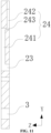
- Fig. 9 is a bottom view of a coating gasket 400 according to an embodiment of the present application
- Fig. 10 is a top view of a coating gasket 400 according to an embodiment of the present application
- Fig. 11 is a cross-sectional view along B-B in Fig. 9 .
- the groove portion 24 of the second flow channel 2 includes an inlet section 241, an outlet section 242 and a communication section 243; in the thickness direction Z of the gasket, the inlet section 241 and the outlet section 242 are respectively located on two sides of the coating gasket 400; and the inlet section 241 is connected to the slurry inlet 23, the communication section 243 is connected to the inlet section 241 and the outlet section 242, and the outlet section 242 is connected to the second slurry outlet 21.
- slurry inlets 23 penetrate the coating gasket 400 in the thickness direction Z of the gasket.
- the slurry inlets 23 of the second flow channel 2 that are located in the middle of the coating gasket 400 are strip-shaped through holes in the shape of a right angle, and the slurry inlets 23 of the second flow channel 2 that are located at two side ends of the gasket are circular through holes.
- the position and the specific shape of the slurry inlet 23 are specifically set according to the position where the slurry flows out of the upper die 200 or the lower die 300 and the function of the slurry inlet 23 is to introduce the second slurry stored in the upper die 200 or the lower die 300 into the second flow channel 2 to realize the coating of the second coating layer.
- the specific shape of the slurry inlet 23 is not limited in the present application, as long as the second slurry can be introduced.
- the inlet section 241 of the groove portion 24 is located on the same side of the gasket as the slope portion 12 of the first flow channel 1 in the thickness direction Z of the gasket. In the width direction Y, the inlet section 241 and the slope 12 keep a distance to prevent the second flow channel 2 from interfering with the first flow channel 1 to mix the first slurry and the second slurry.
- the inlet sections 241 of the second flow channel 2 that are located in the middle of the gasket are elongated groove bodies extending in the width direction Y, while the inlet sections 241 of the second flow channel 2 that are located at the two side ends of the gasket are inclined elongated groove bodies at an angle with respect to the width direction Y
- the position and the specific shape of the inlet section 241 are determined according to the specific position of the slurry inlet 23.
- the function of the inlet section 241 is to introduce the second slurry flowing in from the slurry inlet 23 into the communication section 243 and into the outlet section 242 through the communication section 243.
- the specific shape of the inlet section 241 is not limited in the present application.
- the outlet section 242 of the groove portion 24 is located on the side of the coating gasket 400 opposite to the inlet section 241 in the thickness direction Z of the gasket.
- One end of the outlet section 242 is connected to the communication section 243, and the other end thereof is connected to the second slurry outlet 21.
- the outlet sections 242 of the second flow channel 2 that are located in the middle of the gasket are strip-shaped groove bodies extending in the width direction Y, while the outlet sections 242 of the second flow channel 2 that are located at the two side ends of the gasket are bent groove bodies.
- the function of the outlet section 242 is to lead out the second slurry flowing out of the inlet section 241 to the second slurry outlet 21, so as to coat the object 500 to be coated.
- the position and the specific shape of the outlet section 242 are determined according to the positions and the shapes of the slurry inlet 23 and the inlet section 241, and it is necessary to make the projections of the first slurry outlet 11 and the second slurry outlet 21 partially overlap in the thickness direction Z of the gasket.
- the shape of the flow channel of the second flow channel 2 is adaptively set according to the outlet of the upper die 200 or the lower die 300 of the coating device 100 for the second slurry.
- the inlet section 241 and the outlet section 242 of the second flow channel 2 are respectively arranged on two sides of the gasket in the thickness direction Z of the gasket, so that the slurry flows out more smoothly and the application range of the coating gasket 400 is increased.
- the gasket has a thickness of 0.2-5 mm; and in the thickness direction Z of the gasket, the inlet section 241 and the outlet section 242 each have a depth of 5%-95% of the thickness of the gasket.
- the setting of the depth of the inlet section 241 and the outlet section 242 can make the second slurry flow out along the second flow channel 2, ensure the strength of the coating gasket 400, and ensure that the first slurry outlet 11 and the second slurry outlet 21 of the coating gasket 400 partially overlap in the thickness direction Z of the gasket.
- the present application also provides a coating device 100 using the coating gasket 400 described above.
- the coating device 100 includes an upper die 200 and a lower die 300, and the coating gasket 400 is arranged between the upper die 200 and the lower die 300.
- the coating gasket 400 of the present application is provided with a plurality of first flow channels 1 arranged side-by-side, second flow channels 2 are provided on two sides of each first flow channel 1, and the first slurry outlet 11 of the first flow channel 1 and the second slurry outlet 21 of the second flow channel 2 partially overlap in the thickness direction Z of the gasket, so that the first coating layer and the second coating layer partially overlap in the thickness direction Z of the gasket.
- the first coating layer partially covers the second coating layer.
- the second slurry is prevented from penetrating towards the first slurry to the upper surface of the first coating layer, thereby preventing the problem of the unclear boundary between the first coating layer and the second coating layer at the adjacent position.
- the first slurry is an active material, which is applied to the electrode sheet of the battery to form an active material layer; and the second slurry is an insulating material, which is applied to the electrode sheet of the battery to form an insulating layer.
- the active material layer covers the edge of the insulating layer to prevent the insulating layer from penetrating to the surface of the active material layer so that a clear boundary is formed.
- the die-cutting position of the tab is determined according to the clear boundary formed between the active material layer and the insulating layer, improving the dimensional accuracy of the electrode sheet.
Landscapes
- Engineering & Computer Science (AREA)
- Manufacturing & Machinery (AREA)
- Chemical & Material Sciences (AREA)
- Chemical Kinetics & Catalysis (AREA)
- Electrochemistry (AREA)
- General Chemical & Material Sciences (AREA)
- Coating Apparatus (AREA)
- Battery Electrode And Active Subsutance (AREA)
- Gasket Seals (AREA)
Abstract
Description
- The present application claims priority to
Chinese Patent Application No. 202110873212.0, entitled "COATING SHIM AND COATING DEVICE" and filed on July 30, 2021 - The present application relates to the technical field of battery manufacturing, and in particular to a coating gasket and a coating device.
- In the battery production process, it is necessary to coat an active material layer and an insulating layer on an electrode sheet of the battery. After the coating of the electrode sheet of the battery is completed, it is necessary to determine a die-cutting position of a tab according to a boundary position of the active material layer and the insulating layer. When an existing coating device is used to jointly coat the active material layer and the insulating layer on the electrode sheet of the battery, the active material layer and the insulating layer are likely to be mixed during a drying process, resulting in an unclear boundary position, which leads to deviation in the determination of the die-cutting position of the tab, and reduces the dimensional accuracy of the electrode sheet.
- The present application provides a coating gasket and a coating device, so as to form a clear boundary when an active material layer and an insulating layer are jointly coated on an electrode sheet of a battery.
- A first aspect of the present application provides a coating gasket for applying a first slurry and a second slurry to an object to be coated. The coating gasket includes: a first flow channel for applying the first slurry to the object to be coated to form a first coating layer; and a second flow channel for applying the second slurry to the object to be coated to form a second coating layer. The first flow channel has a first slurry outlet at a first end face of the gasket facing the object to be coated, the second flow channel has a second slurry outlet at the first end face, and the first slurry outlet and the second slurry outlet are configured to partially overlap in a thickness direction of the gasket, such that the first coating layer and the second coating layer partially overlap in the thickness direction of the gasket.
- The first slurry outlet and the second slurry outlet partially overlap in the thickness direction of the gasket. When the object to be coated is being coated, the first coating layer partially covers the second coating layer, thereby reducing the problem of the unclear boundary between the first coating layer and the second coating layer at the adjacent position.
- In some embodiments, the first slurry outlet is arranged spaced apart from the second slurry outlet.
- With the spaced arrangement between the first slurry outlet and the second slurry outlet, when the object to be coated is being coated, the first slurry and the second slurry can be fully layered, thereby reducing the possibility of the first slurry and the second slurry penetrating into and mixing with each other during coating, so that a well-defined boundary is formed between the first coating layer and the second coating layer.
- In some embodiments, the height of the second slurry outlet in the thickness direction is less than the thickness of the gasket, so that the first slurry outlet can partially cover the second slurry outlet in the thickness direction of the gasket, thereby ensuring that the first slurry outlet partially overlaps with the second slurry outlet in the thickness direction of the gasket.
- In some embodiments, the first slurry outlet and the second slurry outlet have an overlapping width of 0.1-9 mm in an arrangement direction of the first flow channel and the second flow channel.
- The overlapping width is set such that the first slurry outlet is lap jointed to the second slurry outlet, to enable an edge of the first coating layer to cover an edge of the second coating layer.
- In some embodiments, the second flow channel comprises an opening portion extending to the second slurry outlet, the opening portion having a width in the arrangement direction of the first flow channel and the second flow channel that gradually increases in a direction from a slurry inlet of the second flow channel to the second slurry outlet.
- With the provision of the opening portion extending to the second slurry outlet, when the second slurry flows to the opening portion along the second flow channel, the width of the flow channel increases, but the flow rate of the second slurry remains unchanged, so that the depth of the second slurry in the opening portion in the thickness direction of the gasket becomes smaller, thereby making the second coating layer applied to the object to be coated thinner.
- In some embodiments, the first flow channel has a side surface in the arrangement direction of the first flow channel and the second flow channel that comprises a slope portion and a step portion connected to each other, the slope portion partially overlapping with the second slurry outlet in the thickness direction of the gasket.
- With the provision of the side surface of the first flow channel with a slope portion, the first slurry flowing out of the first flow channel through the slope portion is relatively thin, so that the coating thickness at the overlapping position of the first coating layer and the second coating layer will not be significantly increased to form a protrusion, and the overall thickness of the first coating layer thus remains uniform.
- In some embodiments, the step portion has a height of 0.01-4.8 mm in the thickness direction of the gasket.
- The setting of the height of the step portion not only ensures that the slope portion partially overlaps with the second slurry outlet in the thickness direction of the gasket, but also ensures the structural strength of the coating gasket.
- In some embodiments, the slope portion has a width in the arrangement direction of the first flow channel and the second flow channel that is not greater than 10 mm.
- The setting of the width of the slope portion can not only ensure that the slope portion fully covers the second slurry outlet, but can also ensure the width of the part of the second slurry outlet that is not covered by the slope portion, thereby ensuring that the first coating layer partially covers the second coating layer, and ensuring the width of the exposed part of the second coating layer.
- In some embodiments, the slope portion has a length of 1-50 mm in an outflow direction of the first slurry.
- The length of the slope portion is set such that the slope portion covers, in a width direction, the edge of the second flow channel for a certain length, which can ensure that when flowing out, the first slurry covers the second slurry.
- In some embodiments, the second flow channel comprises a groove portion for communicating the slurry inlet of the second flow channel and the second slurry outlet, and the slurry inlet penetrates the gasket in the thickness direction of the gasket.
- The slurry inlet is configured to penetrate the coating gasket, which can be applied to the situation where the second slurry flows into the coating gasket from an upper die or a lower die of the coating device, thereby increasing the application range of the coating gasket.
- In some embodiments, the groove portion comprises an inlet section, an outlet section and a communication section; in the thickness direction of the gasket, the inlet section and the outlet section are respectively located on two sides of the gasket; and the inlet section is connected to the slurry inlet, the communication section is connected to the inlet section and the outlet section, and the outlet section is connected to the second slurry outlet.
- According to the outlet of the second slurry of the upper die or the lower die of the coating device, the flow channel of the second flow channel is adaptively shaped such that the coating gasket can adapt to different working conditions, thereby increasing the application range of the coating gasket.
- In some embodiments, the gasket has a thickness of 0.2-5 mm, and the inlet section and the outlet section each have a depth of 5%-95% of the thickness of the gasket.
- The setting of the depth of the inlet section and the outlet section can make the second slurry flow out along the second flow channel, ensure the strength of the coating gasket, and ensure that the first slurry outlet and the second slurry outlet of the coating gasket partially overlap in the thickness direction of the gasket.
- A second aspect of the present application provides a coating device, including a lower die, an upper die, and the coating gasket as described above, the coating gasket being arranged between the upper die and the lower die.
- In the coating gasket and the coating device of the present application, the first slurry outlet of the first flow channel and the second slurry outlet of the second flow channel partially overlap in the thickness direction of the gasket, so that the first coating layer and the second coating layer partially overlap in the thickness direction of the gasket. The first coating layer partially covers the second coating layer, thereby reducing the problem of the unclear boundary between the first coating layer and the second coating layer at the adjacent position. When the object to be coated is an electrode sheet of the battery, during die-cutting of a tab for the electrode sheet, the die-cutting position of the tab is determined according to the clear boundary formed between the first coating layer and the second coating layer, improving the dimensional accuracy of the electrode sheet.
- In order to more clearly illustrate the technical solutions of the embodiments of the present application, the drawings to be used in the embodiments of the present application will be described briefly below. It will be apparent that the drawings in the following description are merely particular embodiments of the present application. Those skilled in the art can obtain other drawings according to these drawings without any creative effort.
-
Fig. 1 is an exploded structural schematic view of a coating device according to an embodiment of the present application; -
Fig. 2 is a schematic view of an object to be coated being coated by a coating device according to an embodiment of the present application; -
Fig. 3 is a perspective structural schematic view of a coating gasket according to an embodiment of the present application. -
Fig. 4 is a front view of a coating gasket according to an embodiment of the present application. -
Fig. 5 is an enlarged view of part I ofFig. 4 ; -
Fig. 6 is a partial enlarged front view of a coating gasket according to another embodiment; -
Fig. 7 is a partial schematic view of a specific embodiment in a direction A inFig. 5 ; -
Fig. 8 is a partial schematic view of another specific embodiment in the direction A inFig. 5 ; -
Fig. 9 is a bottom view of a coating gasket according to an embodiment of the present application; -
Fig. 10 is a top view of a coating gasket according to an embodiment of the present application; and -
Fig. 11 is a cross-sectional view along B-B inFig. 9 . -
- 100. Coating device;
- 101. End face;
- 200. Upper die;
- 300. Lower die;
- 400. Coating gasket;
- 401. First end face;
- 500. Object to be coated;
- 600. Drive roller;
- 1. First flow channel;
- 11. First slurry outlet;
- 12. Slope portion;
- 13. Step portion;
- 2. Second flow channel;
- 21. Second slurry outlet;
- 22. Opening portion;
- 23. Slurry inlet;
- 24. Groove portion;
- 241. Inlet section;
- 242. Outlet section;
- 243. Communication section;
- 3. Mounting hole;
- X. Length direction of the coating gasket (arrangement direction of the first flow channel and the second flow channel);
- Y. Width direction of the coating gasket (slurry outflow direction);
- Z. Thickness direction of the gasket;
- h1. Distance between the first slurry outlet and the second slurry outlet in the thickness direction of the gasket;
- h2. Height of the second slurry outlet in the thickness direction of the gasket;
- h3. Thickness of the coating gasket;
- h4. Height of the step portion in the thickness direction of the gasket;
- w1. Distance between the first slurry outlet and the second slurry outlet in the length direction;
- w2. Overlapping width of the first slurry outlet and the second slurry outlet in the length direction;
- w3. Width of the slope portion in the length direction;
- L. Length of the slope portion in the width direction;
- The drawings herein, which are incorporated into and constitute a part of the specification, illustrate embodiments consistent with the present application and, together with the specification, are used to explain principles of the present application.
- In order to better understand the technical solutions of the present application, embodiments of the present application are described in detail below with reference to the accompanying drawings.
- It should be clear that the following embodiments are only some of the embodiments of the present application. All the other embodiments obtained by those skilled in the art based on the following embodiments without any creative effort shall fall within the scope of protection of the present application.
- The terms used in the embodiments of the present application are merely for the purpose of describing specific embodiments, and are not intended to limit the present application. The terms "a/an", "said", and "the" in the singular form used in the embodiments of the present application and the appended claims are also intended to include the plural form unless otherwise clearly indicated in the context.
- It should be understood that the term "and/or" used herein is only an association relationship for describing associated objects, indicating that three relationships may exist. For example, A and/or B may represent three situations: A exists alone, both A and B exist, and B exists alone. In addition, the character "/" herein generally indicates an "or" relationship between the associated objects.
- It should be noted that the orientation terms such as "upper", "lower", "left" and "right" described in embodiments of the present application are described from the angle shown in the accompanying drawings, and should not be construed as limiting the embodiments of the present application. In addition, in the context, it also needs to be understood that when it is mentioned that an element is connected to an "upper" or "lower" portion of another element, it can not only be directly connected to the "upper" or "lower" portion of the another element, but also indirectly connected to the "upper" or "lower" portion of the another element via an intermediate element.
- In the battery production process, it is necessary to coat an active material layer and an insulating layer on an electrode sheet of the battery. After the coating of the electrode sheet of the battery is completed, it is necessary to determine a die-cutting position of a tab according to a boundary position of the active material layer and the insulating layer.
- The applicant has found that when an existing coating device is used to jointly coat the active material layer and the insulating layer on a current collector of the electrode sheet of the battery, the active material layer and the insulating layer are likely to be mixed during a drying process, resulting in an unclear boundary position, which leads to deviation in the determination of the die-cutting position of the tab, and reduces the dimensional accuracy of the electrode sheet of the battery.
- Based on the above problems discovered by the applicant, the applicant improved the structure of the coating gasket of the coating device, and embodiments of the present application will be further described below.
-
Fig. 1 is an exploded structural schematic view of acoating device 100 according to an embodiment of the present application. - As shown in
Fig. 1 , thecoating device 100 provided by the present application includes anupper die 200, alower die 300, and acoating gasket 400 arranged between theupper die 200 and thelower die 300. -
Fig. 2 is a schematic view of anobject 500 to be coated being coated by acoating device 100 according to an embodiment of the present application. - As shown in
Fig. 2 , when thecoating device 100 performs a coating operation on theobject 500 to be coated, anend face 101 of thecoating device 100 perpendicular to a slurry outflow direction (the direction of the arrow in the figure) faces theobject 500 to be coated, to perform a coating operation on theobject 500 to be coated. Theobject 500 to be coated is transported on adrive roller 600, so that theobject 500 to be coated is transported to the position of theend face 101 of thecoating device 100, so as to realize continuous coating of theobject 500 to be coated. - In the following embodiments, the slurry outflow direction is defined as a width direction Y of the
coating gasket 400, and the width direction Y mentioned herein is the slurry outflow direction. - In this embodiment, the
coating device 100 can simultaneously apply two slurries to theobject 500 to be coated, to form two different coatings. For example, a first slurry is delivered from thelower die 300 to thecoating gasket 400, and a second slurry is delivered from theupper die 200 or thelower die 300 to thecoating gasket 400. The first slurry and the second slurry flow out, through outlets respectively provided on thecoating gasket 400, to theend face 101 perpendicular to the width direction Y, and are applied to theobject 500 to be coated. - The second slurry may be delivered from the
upper die 200 to thecoating gasket 400, or from thelower die 300 to thecoating gasket 400, which can be set according to the actual usage and the structure of thecoating gasket 400. - In this embodiment, the
object 500 to be coated is described in detail as a current collector of an electrode sheet of a battery. Of course, the present application is not limited to the coating of the current collector of the electrode sheet of the battery. Theobject 500 to be coated may be any carrier that needs to be coated with a coating. The first slurry may be an active material, which is applied to the current collector to form an active material layer; and the second slurry may be an insulating material, which is applied to the current collector to form an insulating layer. - The current collector is a continuous foil, which is transported on the
drive roller 600. When the current collector is conveyed to theend face 101 of thecoating device 100, a slurry flows out of a slurry outlet of thecoating device 100 that is provided on theend face 101, and is applied to the current collector, such that a continuous coating layer is formed on the current collector. After the coating is completed, the current collector coated with the coating layer is die-cut according to the size of the electrode sheet of the battery, to obtain an electrode sheet of the battery of a predetermined size. -
Fig. 3 is a perspective structural schematic view of acoating gasket 400 according to an embodiment of the present application. - As shown in
Fig. 3 , acoating gasket 400 according to an embodiment of the present application is used for applying a first slurry and a second slurry to anobject 500 to be coated. Thecoating gasket 400 includes afirst flow channel 1 and asecond flow channel 2. Thefirst flow channel 1 is used for applying the first slurry to theobject 500 to be coated, to form a first coating layer, and thesecond flow channel 2 is used for applying the second slurry to theobject 500 to be coated, to form a second coating layer. A plurality of mountingholes 3 are further provided in thecoating gasket 400 for fixed connection with theupper die 200 and thelower die 300. -
Second flow channels 2 are respectively arranged on two sides of thefirst flow channel 1 of thecoating gasket 400 inFig. 3 . The respective arrangement of thesecond flow channels 2 on the two sides of thefirst flow channel 1 enables second coating layers to be coated to both sides of the first coating layer when the current collector is being coated. After the coating is completed, the current collector is die-cut in the middle of the first coating layer, so that two electrode sheets of the battery can be formed, each electrode sheet of the battery is coated with the first coating layer, and the edge of the first coating layer is coated with the second coating layer. - Moreover, as shown in
Fig. 3 , twofirst flow channels 1 are arranged side-by-side on thecoating gasket 400 in an arrangement direction of thefirst flow channels 1 and thesecond flow channels 2. In this way, it is possible to realize the coating of multiple electrode sheets of the battery for one current collector through one coating operation, improves the coating efficiency. - Similarly, it is also possible that, according to the sizes of the current collector and the electrode sheet of the battery, a plurality of
first flow channels 1 are arranged side-by-side on thecoating gasket 400, andsecond flow channels 2 are respectively arranged on two sides of eachfirst flow channel 1, so that multiple electrode sheets of the battery are coated through one coating operation. - In the following embodiments, the arrangement direction of the
first flow channel 1 and thesecond flow channel 2 is defined as a length direction X of thecoating gasket 400, and the length direction X mentioned herein is the arrangement direction of thefirst flow channel 1 and thesecond flow channel 2. -
Fig. 4 is a front view of acoating gasket 400 according to an embodiment of the present application. - As shown in
Fig. 4 , thecoating gasket 400 has afirst end face 401 on the side facing theobject 500 to be coated. Thefirst end face 401 is perpendicular to the width direction Y Thefirst flow channel 1 has afirst slurry outlet 11 at thefirst end face 401, thesecond flow channel 2 has asecond slurry outlet 21 at thefirst end face 401, and thefirst slurry outlet 11 and thesecond slurry outlet 21 are configured to have projections in a thickness direction Z of the gasket partially overlapping, so that projections of the first coating layer and the second coating layer partially overlap in the thickness direction Z of the gasket. - As shown in
Fig. 4 , thefirst slurry outlet 11 is partially located above thesecond slurry outlet 21. When theobject 500 to be coated is being coated, the first slurry flows out from thefirst slurry outlet 11, and the second slurry flows out from thesecond slurry outlet 21, such that the first slurry partially covers the second slurry, and the first slurry and the second slurry respectively form the first coating layer and the second coating layer applied to the foil of the current collector of the electrode sheet of the battery. The first coating layer partially covers the second coating layer, and during the drying process, the second slurry is prevented from penetrating towards the first slurry to an upper surface of the first coating layer, thereby avoiding the problem of the unclear boundary between the first coating layer and the second coating layer at the adjacent position. -
Fig. 5 is an enlarged view of part I ofFig. 4 . - As shown in
Fig. 5 , the projections of thefirst slurry outlet 11 and thesecond slurry outlet 21 partially overlap in the thickness direction Z of the gasket, but thefirst slurry outlet 11 is not in communication with thesecond slurry outlet 21. A distance h1 is reserved in the thickness direction Z of the gasket, and a distance w1 is reserved in the length direction X, so that thefirst slurry outlet 11 is arranged spaced apart from thesecond slurry outlet 21. - In some embodiments, the
first flow channel 1 is arranged spaced apart from thesecond flow channel 2 to reduce the possibility of mixing between the first slurry and the second slurry due to contact. - As shown in
Fig. 5 , thesecond slurry outlet 21 has a height h2 of in the thickness direction Z of the gasket that is less than a thickness h3 of thecoating gasket 400, and thefirst slurry outlet 11 has a height equal to the thickness h3 of thecoating gasket 400. That is, thefirst slurry outlet 11 is an opening that runs through the entire thickness of the gasket. Since the height h2 of thesecond slurry outlet 21 is less than the thickness h3 of thecoating gasket 400, thefirst slurry outlet 11 can be partially located above thesecond slurry outlet 21 in the thickness direction Z of the gasket, thereby ensuring that thefirst slurry outlet 11 partially overlaps with thesecond slurry outlet 21 in the thickness direction Z of the gasket. - In a specific embodiment, the thickness h3 of the
coating gasket 400 is preferably 0.2-5 mm, and the height h2 of thesecond slurry outlet 21 is preferably 5%-95% of the thickness h3, so as to ensure the strength of thecoating gasket 400, and ensure that thefirst slurry outlet 11 on thecoating gasket 400 can partially overlap with thesecond slurry outlet 21 in the thickness direction Z of the gasket. - In a specific embodiment, the
first slurry outlet 11 and thesecond slurry outlet 21 have an overlapping width w2 of 0.1-9 mm in the length direction X. The overlapping width w2 is set such that the first slurry flowing out of thefirst slurry outlet 11 is lap jointed to the second slurry flowing out of thesecond slurry outlet 21, to enable an edge of the first coating layer to cover an edge of the second coating layer. - The size of the overlapping width w2 can be adjusted by changing the width and the position of the
second slurry outlet 21. In a specific embodiment, in the length direction X, the overlapping width w2 does not exceed 20% of the width of thesecond slurry outlet 21, so as to not only ensure that the edge of the first coating layer covers the edge of the second coating layer and but also ensure the width of the second coating layer. -
Fig. 6 is a partial enlarged front view of acoating gasket 400 according to another embodiment. - As shown in
Fig. 6 , thefirst flow channel 1 has a side surface in the longitudinal direction X that includes aslope portion 12 and astep portion 13 connected to each other. Projections of theslope portion 12 and thesecond slurry outlet 21 partially overlap in the thickness direction Z of the gasket. With the provision of theslope portion 12 and thestep portion 13 connected to each other on the side surface of thefirst flow channel 1 in the length direction X, a side end of theslope portion 12 is connected to an end of thestep portion 13 in the thickness Z direction of the gasket, and the other side end thereof is inclined toward thesecond slurry outlet 21 in the length direction X, located above thesecond slurry outlet 21 in the thickness direction Z of the gasket, and makes the first slurry flowing out of thefirst flow channel 1 through theslope portion 12 thinner in the thickness direction Z of the gasket, so that the coating thickness where the first coating layer is lap jointed to the second coating layer will not be significantly increased to form a protrusion, and the overall thickness of the first coating layer thus remains uniform. The height of thestep portion 13 and the angle of theslope portion 12 should be set to ensure that the projections of theslope portion 12 and thesecond slurry outlet 21 partially overlap in the thickness direction Z of the gasket, so as to ensure that the first coating layer partially covers the second coating layer when the first slurry and the second slurry are being applied to theobject 500 to be coated. - In some embodiments, the height h2 of the
second slurry outlet 21 is preferably 5%-95% of the thickness h3, that is, h2 = (5%-95%) × h3; and the height h4 of thestep portion 13 is less than the height h2 of thesecond slurry outlet 21 in the thickness direction Z of the gasket, that is, h4 < h2. - In a specific embodiment, the thickness h3 of the
coating gasket 400 is preferably 0.2-5 mm, the height h4 of thestep portion 13 in the thickness direction Z of the gasket is 0.01-4.8 mm, and the height of thestep portion 13 is set to not only ensure that the projections of theslope portion 12 and thesecond slurry outlet 21 partially overlap in the thickness direction Z of the gasket, but also ensure the structural strength of thecoating gasket 400. -
Fig. 7 is a partial schematic view of a specific embodiment in a direction A inFig. 5 . - As shown in
Fig. 7 , in a specific embodiment, theslope portion 12 extends toward the outer side of thefirst flow channel 1 in the length direction X, so that the projections of the slope portion and thesecond slurry outlet 21 partially overlap in the thickness direction Z of the gasket. In this embodiment, in the length direction X, the width of thefirst flow channel 1 at the position where the first slurry flows in is less than the width of thefirst slurry outlet 11. That is, thefirst flow channel 1 has an increased width at the position of theslope portion 12, so that after flowing to theslope portion 12, the first slurry flows out to thefirst slurry outlet 11 along theslope portion 12. -
Fig. 8 is a partial schematic view of another specific embodiment in the direction A inFig. 5 . - As shown in
Fig. 8 , in another specific embodiment, theslope portion 12 extends toward the inner side of thefirst flow channel 1 in the length direction X, so that the projections of the slope portion and thesecond slurry outlet 21 partially overlap in the thickness direction Z of the gasket. In this embodiment, in the length direction X, the width of thefirst flow channel 1 at the position where the first slurry flows in is greater than the width of thefirst slurry outlet 11. That is, thefirst flow channel 1 has a decreased width at the position of theslope portion 12, so that after flowing to theslope portion 12, the first slurry flows out to thefirst slurry outlet 11 along theslope portion 12. - The extension direction of the
slope portion 12 in the length direction X is set according to the positional relationship between thefirst flow channel 1 and thesecond flow channel 2 on thecoating gasket 400 and the widths of thefirst slurry outlet 11 and thesecond slurry outlet 21, so as to realize the coating of the first coating layer and the second coating layer with predetermined widths, and realize that the first coating layer partially covers the second coating layer. - In a specific embodiment, the width w3 of the
slope portion 12 in the length direction X (the arrangement direction of thefirst flow channel 1 and the second flow channel 2) is not greater than 10 mm. The setting of the width of theslope portion 12 can not only ensure that theslope portion 12 fully covers thesecond slurry outlet 21, but can also ensure the width of the part of thesecond slurry outlet 21 that is not covered by theslope portion 12, thereby ensuring that the first coating layer partially covers the second coating layer, and ensuring the width of the exposed part of the second coating layer. - In some embodiments, in the width direction Y (the outflow direction of the first slurry), the
slope portion 12 has a length L less than that of the first flow channel. In a specific embodiment, the length L of theslope portion 12 is 1-50 mm. The length of theslope portion 13 is set such that theslope portion 12 covers, in the width direction Y, the edge of thesecond flow channel 2 for a certain length, which can ensure that when flowing out, the first slurry covers the second slurry. - As shown in
Figs. 7 and 8 , in some embodiments, thesecond flow channel 2 comprises an openingportion 22. The openingportion 22 extends to thesecond slurry outlet 21, and the openingportion 22 has a width in the length direction X (the arrangement direction of the first flow channel and the second flow channel) that gradually increases in a direction from aslurry inlet 23 of thesecond flow channel 2 to thesecond slurry outlet 21. With the provision of the openingportion 22 extending to thesecond slurry outlet 21, when the second slurry flows to the openingportion 22 along thesecond flow channel 2, the width of the flow channel increases, but the flow rate of the second slurry remains unchanged, so that the depth of the second slurry in the openingportion 22 in the thickness direction Z of the gasket becomes smaller, thereby making the second coating layer applied from thesecond slurry outlet 21 to theobject 500 to be coated thinner. - In some embodiments, as shown in
Figs. 5 to 8 , thesecond flow channel 2 includes agroove portion 24 having a height in the thickness direction of the gasket that is less than the thickness of the gasket, thegroove portion 24 communicates theslurry inlet 23 of thesecond flow channel 2 with thesecond slurry outlet 21, and theslurry inlet 23 penetrates thecoating gasket 400 in the thickness direction Z of the gasket. The second slurry flows into thegroove portion 24 from theslurry inlet 23, and flows to thesecond slurry outlet 21 through the openingportion 22, so as to apply the second coating layer to theobject 500 to be coated. Theslurry inlet 23 is configured to penetrate thecoating gasket 400, which can be applied to the situation where the second slurry flows into thecoating gasket 400 from theupper die 200 or thelower die 300 of thecoating device 100, thereby increasing the application range of thecoating gasket 400. -
Fig. 9 is a bottom view of acoating gasket 400 according to an embodiment of the present application;Fig. 10 is a top view of acoating gasket 400 according to an embodiment of the present application; andFig. 11 is a cross-sectional view along B-B inFig. 9 . - In a specific embodiment, as shown in
Figs. 9 to 11 , thegroove portion 24 of thesecond flow channel 2 includes aninlet section 241, anoutlet section 242 and acommunication section 243; in the thickness direction Z of the gasket, theinlet section 241 and theoutlet section 242 are respectively located on two sides of thecoating gasket 400; and theinlet section 241 is connected to theslurry inlet 23, thecommunication section 243 is connected to theinlet section 241 and theoutlet section 242, and theoutlet section 242 is connected to thesecond slurry outlet 21. - As shown in
Fig. 9 ,slurry inlets 23 penetrate thecoating gasket 400 in the thickness direction Z of the gasket. The slurry inlets 23 of thesecond flow channel 2 that are located in the middle of thecoating gasket 400 are strip-shaped through holes in the shape of a right angle, and theslurry inlets 23 of thesecond flow channel 2 that are located at two side ends of the gasket are circular through holes. In the present application, the position and the specific shape of theslurry inlet 23 are specifically set according to the position where the slurry flows out of theupper die 200 or thelower die 300 and the function of theslurry inlet 23 is to introduce the second slurry stored in theupper die 200 or thelower die 300 into thesecond flow channel 2 to realize the coating of the second coating layer. The specific shape of theslurry inlet 23 is not limited in the present application, as long as the second slurry can be introduced. - The
inlet section 241 of thegroove portion 24 is located on the same side of the gasket as theslope portion 12 of thefirst flow channel 1 in the thickness direction Z of the gasket. In the width direction Y, theinlet section 241 and theslope 12 keep a distance to prevent thesecond flow channel 2 from interfering with thefirst flow channel 1 to mix the first slurry and the second slurry. In the length direction X, theinlet sections 241 of thesecond flow channel 2 that are located in the middle of the gasket are elongated groove bodies extending in the width direction Y, while theinlet sections 241 of thesecond flow channel 2 that are located at the two side ends of the gasket are inclined elongated groove bodies at an angle with respect to the width direction Y In the present application, the position and the specific shape of theinlet section 241 are determined according to the specific position of theslurry inlet 23. The function of theinlet section 241 is to introduce the second slurry flowing in from theslurry inlet 23 into thecommunication section 243 and into theoutlet section 242 through thecommunication section 243. The specific shape of theinlet section 241 is not limited in the present application. - The
outlet section 242 of thegroove portion 24 is located on the side of thecoating gasket 400 opposite to theinlet section 241 in the thickness direction Z of the gasket. One end of theoutlet section 242 is connected to thecommunication section 243, and the other end thereof is connected to thesecond slurry outlet 21. In the length direction X, theoutlet sections 242 of thesecond flow channel 2 that are located in the middle of the gasket are strip-shaped groove bodies extending in the width direction Y, while theoutlet sections 242 of thesecond flow channel 2 that are located at the two side ends of the gasket are bent groove bodies. In the present application, the function of theoutlet section 242 is to lead out the second slurry flowing out of theinlet section 241 to thesecond slurry outlet 21, so as to coat theobject 500 to be coated. The position and the specific shape of theoutlet section 242 are determined according to the positions and the shapes of theslurry inlet 23 and theinlet section 241, and it is necessary to make the projections of thefirst slurry outlet 11 and thesecond slurry outlet 21 partially overlap in the thickness direction Z of the gasket. - The shape of the flow channel of the
second flow channel 2 is adaptively set according to the outlet of theupper die 200 or thelower die 300 of thecoating device 100 for the second slurry. For a structure in which the distance between theslurry inlet 23 and thesecond slurry outlet 21 is relatively large, theinlet section 241 and theoutlet section 242 of thesecond flow channel 2 are respectively arranged on two sides of the gasket in the thickness direction Z of the gasket, so that the slurry flows out more smoothly and the application range of thecoating gasket 400 is increased. - In a specific embodiment, the gasket has a thickness of 0.2-5 mm; and in the thickness direction Z of the gasket, the
inlet section 241 and theoutlet section 242 each have a depth of 5%-95% of the thickness of the gasket. The setting of the depth of theinlet section 241 and theoutlet section 242 can make the second slurry flow out along thesecond flow channel 2, ensure the strength of thecoating gasket 400, and ensure that thefirst slurry outlet 11 and thesecond slurry outlet 21 of thecoating gasket 400 partially overlap in the thickness direction Z of the gasket. - The present application also provides a
coating device 100 using thecoating gasket 400 described above. Thecoating device 100 includes anupper die 200 and alower die 300, and thecoating gasket 400 is arranged between theupper die 200 and thelower die 300. - The
coating gasket 400 of the present application is provided with a plurality offirst flow channels 1 arranged side-by-side,second flow channels 2 are provided on two sides of eachfirst flow channel 1, and thefirst slurry outlet 11 of thefirst flow channel 1 and thesecond slurry outlet 21 of thesecond flow channel 2 partially overlap in the thickness direction Z of the gasket, so that the first coating layer and the second coating layer partially overlap in the thickness direction Z of the gasket. The first coating layer partially covers the second coating layer. During the drying process, the second slurry is prevented from penetrating towards the first slurry to the upper surface of the first coating layer, thereby preventing the problem of the unclear boundary between the first coating layer and the second coating layer at the adjacent position. When theobject 500 to be coated is an electrode sheet of the battery, the first slurry is an active material, which is applied to the electrode sheet of the battery to form an active material layer; and the second slurry is an insulating material, which is applied to the electrode sheet of the battery to form an insulating layer. The active material layer covers the edge of the insulating layer to prevent the insulating layer from penetrating to the surface of the active material layer so that a clear boundary is formed. During die-cutting of a tab for the electrode sheet of the battery, the die-cutting position of the tab is determined according to the clear boundary formed between the active material layer and the insulating layer, improving the dimensional accuracy of the electrode sheet. - What are described above are only preferred embodiments of the present application and are not intended to limit the present application. For those skilled in the art, the present application may have various modifications and changes. Any modifications, equivalent substitutions, improvements, etc. made within the spirit and principles of the present application shall fall into the scope of protection of the present application.
Claims (13)
- A coating gasket (400) for applying a first slurry and a second slurry to an object to be coated, the coating gasket (400) comprising:a first flow channel (1) for applying the first slurry to the object to be coated to form a first coating layer; anda second flow channel (2) for applying the second slurry to the object to be coated to form a second coating layer,wherein the first flow channel (1) has a first slurry outlet (11) at a first end face (401) of the gasket facing the object to be coated, the second flow channel (2) has a second slurry outlet (21) at the first end face (401), and the first slurry outlet (11) and the second slurry outlet (21) are configured to partially overlap in a thickness direction of the gasket, such that the first coating layer and the second coating layer partially overlap in the thickness direction of the gasket.
- The coating gasket (400) according to claim 1, wherein the first slurry outlet (11) is arranged spaced apart from the second slurry outlet (21).
- The coating gasket (400) according to claim 1 or 2, wherein the height of the second slurry outlet (21) in the thickness direction of the gasket is less than the thickness of the gasket.
- The coating gasket (400) according to any one of claims 1-3, wherein the first slurry outlet (11) and the second slurry outlet (21) have an overlapping width of 0.1-9 mm in an arrangement direction of the first flow channel (1) and the second flow channel (2).
- The coating gasket (400) according to any one of claims 1-4, wherein the second flow channel (2) comprises an opening portion (22) extending to the second slurry outlet (21), the opening portion (22) having a width in the arrangement direction of the first flow channel (1) and the second flow channel (2) that gradually increases in a direction from a slurry inlet (23) of the second flow channel (2) to the second slurry outlet (21).
- The coating gasket (400) according to any one of claims 1-5, wherein the first flow channel (1) has a side surface in the arrangement direction of the first flow channel (1) and the second flow channel (2) that comprises a slope portion (12) and a step portion (13) connected to each other, the slope portion (12) partially overlapping with the second slurry outlet (21) in the thickness direction of the gasket.
- The coating gasket (400) according to claim 6, wherein the step portion (13) has a height of 0.01-4.8 mm in the thickness direction of the gasket.
- The coating gasket (400) according to claim 6 or 7, wherein the slope portion (12) has a width in the arrangement direction of the first flow channel (1) and the second flow channel (2) that is not greater than 10 mm.
- The coating gasket (400) according to any one of claims 6-8, wherein the slope portion (12) has a length of 1-50 mm in an outflow direction of the first slurry.
- The coating gasket (400) according to any one of claims 1-9, wherein the second flow channel (2) comprises a groove portion (24) for communicating the slurry inlet (23) of the second flow channel (2) and the second slurry outlet (21), and the slurry inlet (23) penetrates the gasket in the thickness direction of the gasket.
- The coating gasket (400) according to claim 10, wherein the groove portion (24) comprises an inlet section (241), an outlet section (242) and a communication section (243); in the thickness direction of the gasket, the inlet section (241) and the outlet section (242) are respectively located on two sides of the gasket; and the inlet section (241) is connected to the slurry inlet (23), the communication section (243) is connected to the inlet section (241) and the outlet section (242), and the outlet section (242) is connected to the second slurry outlet (21).
- The coating gasket (400) according to claim 11, wherein the gasket has a thickness of 0.2-5 mm, and the inlet section (241) and the outlet section (242) each have a depth of 5%-95% of the thickness of the gasket.
- A coating device (100), comprising:a lower die (300),an upper die (200), andthe coating gasket (400) of any one of claims 1-12, which is arranged between the upper die (200) and the lower die (300).
Applications Claiming Priority (2)
| Application Number | Priority Date | Filing Date | Title |
|---|---|---|---|
| CN202110873212.0A CN115672655B (en) | 2021-07-30 | 2021-07-30 | Coated gaskets and coating equipment |
| PCT/CN2022/097946 WO2023005447A1 (en) | 2021-07-30 | 2022-06-09 | Coating gasket and coating device |
Publications (4)
| Publication Number | Publication Date |
|---|---|
| EP4249134A1 true EP4249134A1 (en) | 2023-09-27 |
| EP4249134A4 EP4249134A4 (en) | 2024-07-31 |
| EP4249134C0 EP4249134C0 (en) | 2025-09-10 |
| EP4249134B1 EP4249134B1 (en) | 2025-09-10 |
Family
ID=85058834
Family Applications (1)
| Application Number | Title | Priority Date | Filing Date |
|---|---|---|---|
| EP22848056.2A Active EP4249134B1 (en) | 2021-07-30 | 2022-06-09 | Coating gasket and coating device |
Country Status (6)
| Country | Link |
|---|---|
| US (2) | US11975355B2 (en) |
| EP (1) | EP4249134B1 (en) |
| CN (1) | CN115672655B (en) |
| ES (1) | ES3054747T3 (en) |
| MX (1) | MX2023007542A (en) |
| WO (1) | WO2023005447A1 (en) |
Cited By (2)
| Publication number | Priority date | Publication date | Assignee | Title |
|---|---|---|---|---|
| EP4670854A1 (en) * | 2024-06-27 | 2025-12-31 | Samsung Sdi Co., Ltd. | SLOTTED NOZZLE COATER |
| EP4711048A1 (en) * | 2024-09-11 | 2026-03-18 | Samsung Sdi Co., Ltd. | Apparatus and method for coating electrode plate of secondary battery, and slot die used in the apparatus and the method |
Families Citing this family (4)
| Publication number | Priority date | Publication date | Assignee | Title |
|---|---|---|---|---|
| KR102865379B1 (en) * | 2021-11-12 | 2025-09-25 | 주식회사 엘지에너지솔루션 | Apparatus and method for electrode coating |
| ES3064316T3 (en) * | 2023-01-28 | 2026-04-23 | Contemporary Amperex Technology Hong Kong Ltd | Coating die head, coating device and battery production device |
| WO2024174139A1 (en) * | 2023-02-22 | 2024-08-29 | 宁德时代新能源科技股份有限公司 | Coating pad, coating device and coating method |
| CN115945358B (en) * | 2023-03-02 | 2023-07-28 | 江苏时代新能源科技有限公司 | Extrusion coating head, coating equipment and coating method |
Family Cites Families (25)
| Publication number | Priority date | Publication date | Assignee | Title |
|---|---|---|---|---|
| JPH078879A (en) * | 1993-06-23 | 1995-01-13 | Hirata Corp | Fluid coating device |
| JP4031635B2 (en) * | 2001-11-08 | 2008-01-09 | Tdk株式会社 | Electrochemical devices |
| US9233500B2 (en) * | 2010-02-08 | 2016-01-12 | 3M Innovative Properties Company | Method of co-extruding, co-extrusion die, and extruded articles made therefrom |
| JP6096077B2 (en) * | 2013-07-25 | 2017-03-15 | オートモーティブエナジーサプライ株式会社 | Coating head and coating apparatus using the same |
| JP6021775B2 (en) * | 2013-09-30 | 2016-11-09 | 株式会社日立ハイテクノロジーズ | Lithium ion secondary battery manufacturing method and lithium ion secondary battery manufacturing apparatus |
| CN204034968U (en) * | 2014-08-13 | 2014-12-24 | 宁德新能源科技有限公司 | Apparatus for coating |
| JP6539069B2 (en) * | 2015-03-09 | 2019-07-03 | 東レエンジニアリング株式会社 | Coating device |
| JP6965162B2 (en) * | 2015-11-06 | 2021-11-10 | 三洋電機株式会社 | Manufacturing method of electrode plate for power storage device |
| CN110198792B (en) * | 2017-02-03 | 2021-10-26 | 日本汽车能源株式会社 | Coating die, coating device, coating method, and method for manufacturing secondary battery |
| EP3609625B1 (en) * | 2017-04-10 | 2025-07-02 | Roche Diabetes Care GmbH | Slot die apparatus and method for applying a plurality of wet films to a substrate using said appratus |
| CN208173722U (en) * | 2017-08-24 | 2018-11-30 | 日立汽车系统株式会社 | Secondary cell |
| JP6927846B2 (en) * | 2017-10-23 | 2021-09-01 | 株式会社ヒラノテクシード | Coating equipment |
| JP2019087305A (en) * | 2017-11-01 | 2019-06-06 | 株式会社日立ハイテクファインシステムズ | Separator slurry, electrode of secondary battery and manufacturing method thereof, and secondary battery |
| CN208527155U (en) * | 2018-05-29 | 2019-02-22 | 安徽力信能源科技有限责任公司 | It is a kind of to be coated with uniform extrusion coating machine die head gasket and die head |
| CN108816565A (en) * | 2018-06-28 | 2018-11-16 | 合肥国轩高科动力能源有限公司 | Anti-mixing dispensing ceramic coating device and method |
| CN209318048U (en) * | 2018-09-30 | 2019-08-30 | 中兴高能技术有限责任公司 | A kind of miniature extrusion coated head |
| JP7155881B2 (en) * | 2018-10-31 | 2022-10-19 | トヨタ自動車株式会社 | Electrode plate, battery using same, method for manufacturing electrode plate, method for manufacturing battery using same, die head |
| CN209406724U (en) * | 2018-12-03 | 2019-09-20 | 银隆新能源股份有限公司 | Die head gasket of extrusion coating machine |
| CN109482428A (en) * | 2018-12-05 | 2019-03-19 | 深圳市曼恩斯特科技有限公司 | Slot coated head |
| CN209544514U (en) * | 2018-12-24 | 2019-10-25 | 江苏时代新能源科技有限公司 | A kind of gasket and its device for battery pole piece coating |
| CN209631524U (en) * | 2019-02-01 | 2019-11-15 | 昆山聚创新能源科技有限公司 | The gasket of extrusion coated device and extrusion coated device with it |
| JP7368125B2 (en) * | 2019-07-05 | 2023-10-24 | 株式会社Aescジャパン | Coating device and method for manufacturing electrodes for batteries |
| JP6781967B1 (en) * | 2020-05-25 | 2020-11-11 | 株式会社タンガロイ | Die head |
| CN213133858U (en) * | 2020-07-02 | 2021-05-07 | 欣旺达电动汽车电池有限公司 | Coated gasket |
| CN213612390U (en) * | 2020-09-30 | 2021-07-06 | 蜂巢能源科技有限公司 | Die head gasket and coating machine for material coating |
-
2021
- 2021-07-30 CN CN202110873212.0A patent/CN115672655B/en active Active
-
2022
- 2022-06-09 WO PCT/CN2022/097946 patent/WO2023005447A1/en not_active Ceased
- 2022-06-09 ES ES22848056T patent/ES3054747T3/en active Active
- 2022-06-09 MX MX2023007542A patent/MX2023007542A/en unknown
- 2022-06-09 EP EP22848056.2A patent/EP4249134B1/en active Active
-
2023
- 2023-07-07 US US18/348,370 patent/US11975355B2/en active Active
-
2024
- 2024-04-01 US US18/623,068 patent/US20240238829A1/en active Pending
Cited By (2)
| Publication number | Priority date | Publication date | Assignee | Title |
|---|---|---|---|---|
| EP4670854A1 (en) * | 2024-06-27 | 2025-12-31 | Samsung Sdi Co., Ltd. | SLOTTED NOZZLE COATER |
| EP4711048A1 (en) * | 2024-09-11 | 2026-03-18 | Samsung Sdi Co., Ltd. | Apparatus and method for coating electrode plate of secondary battery, and slot die used in the apparatus and the method |
Also Published As
| Publication number | Publication date |
|---|---|
| EP4249134A4 (en) | 2024-07-31 |
| EP4249134C0 (en) | 2025-09-10 |
| WO2023005447A1 (en) | 2023-02-02 |
| ES3054747T3 (en) | 2026-02-05 |
| CN115672655A (en) | 2023-02-03 |
| EP4249134B1 (en) | 2025-09-10 |
| US20240238829A1 (en) | 2024-07-18 |
| US20230347373A1 (en) | 2023-11-02 |
| US11975355B2 (en) | 2024-05-07 |
| MX2023007542A (en) | 2023-07-10 |
| CN115672655B (en) | 2024-03-19 |
Similar Documents
| Publication | Publication Date | Title |
|---|---|---|
| EP4249134A1 (en) | Coating gasket and coating device | |
| US20220062944A1 (en) | Coating die, coating device, coating method, and method for manufacturing secondary cell | |
| KR102666576B1 (en) | Slot die coater | |
| EP4410439A1 (en) | Coating die head, and coating device for battery electrode plate | |
| EP4190456B1 (en) | Dual slot die coater including air vent | |
| KR102874374B1 (en) | Slot die coater | |
| CN213133858U (en) | Coated gasket | |
| KR20190096114A (en) | The Die Coater And The Shim For Thereof | |
| EP4154991B1 (en) | Multi-slot die coater with improved manifold | |
| CN114192346B (en) | Coating gasket and coating die | |
| CN116174245B (en) | Coating device | |
| CN217569429U (en) | A coating gasket, die head, pole piece material belt and battery | |
| CN114733714A (en) | Double-layer adhesive dispensing gasket and coating die head | |
| CN217094122U (en) | Coating machine die head gasket and coating machine | |
| CN214812291U (en) | Coating die head | |
| CN117181528A (en) | Coating die head and coating equipment | |
| CN223113430U (en) | Coating gasket and coating machine | |
| KR102893037B1 (en) | Spacer Shim, Slot Die Coater and Coating Method Using the Same | |
| CN117042888A (en) | Insert for tool for slot nozzle coating, tool for slot nozzle coating and method for manufacturing coating | |
| CN222355432U (en) | WIFI ANTENNA | |
| CN222984767U (en) | Gasket assembly, coating device and coating machine | |
| CN223055966U (en) | Coating gasket, coating die head and coating machine | |
| CN222174647U (en) | Coating gasket and coating machine | |
| CN217664306U (en) | Coating gasket and coating die head | |
| KR20260035758A (en) | Coating apparatus |
Legal Events
| Date | Code | Title | Description |
|---|---|---|---|
| STAA | Information on the status of an ep patent application or granted ep patent |
Free format text: STATUS: THE INTERNATIONAL PUBLICATION HAS BEEN MADE |
|
| PUAI | Public reference made under article 153(3) epc to a published international application that has entered the european phase |
Free format text: ORIGINAL CODE: 0009012 |
|
| STAA | Information on the status of an ep patent application or granted ep patent |
Free format text: STATUS: REQUEST FOR EXAMINATION WAS MADE |
|
| 17P | Request for examination filed |
Effective date: 20230620 |
|
| AK | Designated contracting states |
Kind code of ref document: A1 Designated state(s): AL AT BE BG CH CY CZ DE DK EE ES FI FR GB GR HR HU IE IS IT LI LT LU LV MC MK MT NL NO PL PT RO RS SE SI SK SM TR |
|
| A4 | Supplementary search report drawn up and despatched |
Effective date: 20240701 |
|
| RIC1 | Information provided on ipc code assigned before grant |
Ipc: H01M 4/04 20060101ALI20240625BHEP Ipc: B05C 5/02 20060101ALI20240625BHEP Ipc: B05C 9/06 20060101AFI20240625BHEP |
|
| RAP1 | Party data changed (applicant data changed or rights of an application transferred) |
Owner name: CONTEMPORARY AMPEREX TECHNOLOGY(HONG KONG) LIMITED |
|
| DAV | Request for validation of the european patent (deleted) | ||
| DAX | Request for extension of the european patent (deleted) | ||
| GRAP | Despatch of communication of intention to grant a patent |
Free format text: ORIGINAL CODE: EPIDOSNIGR1 |
|
| STAA | Information on the status of an ep patent application or granted ep patent |
Free format text: STATUS: GRANT OF PATENT IS INTENDED |
|
| INTG | Intention to grant announced |
Effective date: 20250403 |
|
| GRAS | Grant fee paid |
Free format text: ORIGINAL CODE: EPIDOSNIGR3 |
|
| GRAA | (expected) grant |
Free format text: ORIGINAL CODE: 0009210 |
|
| STAA | Information on the status of an ep patent application or granted ep patent |
Free format text: STATUS: THE PATENT HAS BEEN GRANTED |
|
| AK | Designated contracting states |
Kind code of ref document: B1 Designated state(s): AL AT BE BG CH CY CZ DE DK EE ES FI FR GB GR HR HU IE IS IT LI LT LU LV MC MK MT NL NO PL PT RO RS SE SI SK SM TR |
|
| REG | Reference to a national code |
Ref country code: GB Ref legal event code: FG4D |
|
| REG | Reference to a national code |
Ref country code: CH Ref legal event code: EP |
|
| REG | Reference to a national code |
Ref country code: DE Ref legal event code: R096 Ref document number: 602022021371 Country of ref document: DE |
|
| REG | Reference to a national code |
Ref country code: IE Ref legal event code: FG4D |
|
| U01 | Request for unitary effect filed |
Effective date: 20251003 |
|
| U07 | Unitary effect registered |
Designated state(s): AT BE BG DE DK EE FI FR IT LT LU LV MT NL PT RO SE SI Effective date: 20251014 |
|
| PG25 | Lapsed in a contracting state [announced via postgrant information from national office to epo] |
Ref country code: NO Free format text: LAPSE BECAUSE OF FAILURE TO SUBMIT A TRANSLATION OF THE DESCRIPTION OR TO PAY THE FEE WITHIN THE PRESCRIBED TIME-LIMIT Effective date: 20251210 |
|
| PG25 | Lapsed in a contracting state [announced via postgrant information from national office to epo] |
Ref country code: HR Free format text: LAPSE BECAUSE OF FAILURE TO SUBMIT A TRANSLATION OF THE DESCRIPTION OR TO PAY THE FEE WITHIN THE PRESCRIBED TIME-LIMIT Effective date: 20250910 |
|
| PG25 | Lapsed in a contracting state [announced via postgrant information from national office to epo] |
Ref country code: GR Free format text: LAPSE BECAUSE OF FAILURE TO SUBMIT A TRANSLATION OF THE DESCRIPTION OR TO PAY THE FEE WITHIN THE PRESCRIBED TIME-LIMIT Effective date: 20251211 |
|
| PG25 | Lapsed in a contracting state [announced via postgrant information from national office to epo] |
Ref country code: PL Free format text: LAPSE BECAUSE OF FAILURE TO SUBMIT A TRANSLATION OF THE DESCRIPTION OR TO PAY THE FEE WITHIN THE PRESCRIBED TIME-LIMIT Effective date: 20250910 |
|
| PG25 | Lapsed in a contracting state [announced via postgrant information from national office to epo] |
Ref country code: RS Free format text: LAPSE BECAUSE OF FAILURE TO SUBMIT A TRANSLATION OF THE DESCRIPTION OR TO PAY THE FEE WITHIN THE PRESCRIBED TIME-LIMIT Effective date: 20251210 |
|
| REG | Reference to a national code |
Ref country code: ES Ref legal event code: FG2A Ref document number: 3054747 Country of ref document: ES Kind code of ref document: T3 Effective date: 20260205 |
|
| PG25 | Lapsed in a contracting state [announced via postgrant information from national office to epo] |
Ref country code: SM Free format text: LAPSE BECAUSE OF FAILURE TO SUBMIT A TRANSLATION OF THE DESCRIPTION OR TO PAY THE FEE WITHIN THE PRESCRIBED TIME-LIMIT Effective date: 20250910 |
|
| PG25 | Lapsed in a contracting state [announced via postgrant information from national office to epo] |
Ref country code: IS Free format text: LAPSE BECAUSE OF FAILURE TO SUBMIT A TRANSLATION OF THE DESCRIPTION OR TO PAY THE FEE WITHIN THE PRESCRIBED TIME-LIMIT Effective date: 20260110 |
|
| PG25 | Lapsed in a contracting state [announced via postgrant information from national office to epo] |
Ref country code: CZ Free format text: LAPSE BECAUSE OF FAILURE TO SUBMIT A TRANSLATION OF THE DESCRIPTION OR TO PAY THE FEE WITHIN THE PRESCRIBED TIME-LIMIT Effective date: 20250910 |
|
| PG25 | Lapsed in a contracting state [announced via postgrant information from national office to epo] |
Ref country code: SK Free format text: LAPSE BECAUSE OF FAILURE TO SUBMIT A TRANSLATION OF THE DESCRIPTION OR TO PAY THE FEE WITHIN THE PRESCRIBED TIME-LIMIT Effective date: 20250910 |