EP4248909A2 - Ersatzbürstenkopf und mundhygienevorrichtung - Google Patents
Ersatzbürstenkopf und mundhygienevorrichtung Download PDFInfo
- Publication number
- EP4248909A2 EP4248909A2 EP23162575.7A EP23162575A EP4248909A2 EP 4248909 A2 EP4248909 A2 EP 4248909A2 EP 23162575 A EP23162575 A EP 23162575A EP 4248909 A2 EP4248909 A2 EP 4248909A2
- Authority
- EP
- European Patent Office
- Prior art keywords
- brush head
- transmission
- replacement brush
- housing
- transmission shaft
- Prior art date
- Legal status (The legal status is an assumption and is not a legal conclusion. Google has not performed a legal analysis and makes no representation as to the accuracy of the status listed.)
- Granted
Links
Images


Classifications
-
- A—HUMAN NECESSITIES
- A61—MEDICAL OR VETERINARY SCIENCE; HYGIENE
- A61C—DENTISTRY; APPARATUS OR METHODS FOR ORAL OR DENTAL HYGIENE
- A61C17/00—Devices for cleaning, polishing, rinsing or drying teeth, teeth cavities or prostheses; Saliva removers; Dental appliances for receiving spittle
- A61C17/16—Power-driven cleaning or polishing devices
- A61C17/22—Power-driven cleaning or polishing devices with brushes, cushions, cups, or the like
- A61C17/32—Power-driven cleaning or polishing devices with brushes, cushions, cups, or the like reciprocating or oscillating
- A61C17/34—Power-driven cleaning or polishing devices with brushes, cushions, cups, or the like reciprocating or oscillating driven by electric motor
- A61C17/3409—Power-driven cleaning or polishing devices with brushes, cushions, cups, or the like reciprocating or oscillating driven by electric motor characterized by the movement of the brush body
- A61C17/3436—Rotation around the axis perpendicular to the plane defined by the bristle holder
-
- A—HUMAN NECESSITIES
- A61—MEDICAL OR VETERINARY SCIENCE; HYGIENE
- A61C—DENTISTRY; APPARATUS OR METHODS FOR ORAL OR DENTAL HYGIENE
- A61C17/00—Devices for cleaning, polishing, rinsing or drying teeth, teeth cavities or prostheses; Saliva removers; Dental appliances for receiving spittle
- A61C17/16—Power-driven cleaning or polishing devices
- A61C17/22—Power-driven cleaning or polishing devices with brushes, cushions, cups, or the like
- A61C17/222—Brush body details, e.g. the shape thereof or connection to handle
Definitions
- the present invention relates to the technical field of oral hygiene supply device, in particular to a replacement brush head and an oral hygiene device.
- the oral hygiene device is generally divided into a replaceable brush head and a handle, and a mechanical movement of the handle is transmitted to the brush head, so as to cause the brush head to move, and then bristles on the brush head to swing to realize the function of cleaning the teeth.
- control degrees of swing arc and swing frequency of the oral hygiene device on the market are different, resulting in different effects on the cleaning degree of the oral cavity.
- the present invention provides a replacement brush head and an oral hygiene device, which solve the technical problems of difficulty in controlling the rotation angle, swing frequency and smooth transmission of the brush head, loud noise in the transmission process and high cost in assembly assistance.
- the present invention provides the following technical solutions:
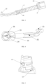
- a replacement brush head comprises: a bristle head 5, a housing 6, a transmission shaft 3 and a tail cover 1, the transmission shaft 3 is arranged inside the housing 6, and the bristle head 5 is arranged in a transmission manner at a top end of the housing 6 through the transmission shaft 3, and the tail cover 1 is arranged at a tail end of the housing 6.
- the transmission shaft 3 includes a transmission rod 30, a top end of the transmission rod 30 is provided with a transmission convex column 32, and the transmission rod 30 is provided with a cross guide groove 31.
- a damping spring 4 is sheathed on the transmission rod 30.
- a tail end of the transmission rod 30 is composed of a peripheral wall and a cavity formed by the peripheral wall, and a plane limiter 36 is provided on an outer side of the peripheral wall, and an assembly positioning groove 35 is provided on an outer side surface adjacent to the plane limiter 36.
- the peripheral wall is further provided with a glue dispensing port 33, and an inner side of the peripheral wall is further provided with a glue overflow groove 34.
- a guide rib 61 and a spring limiting rib 62 are provided on an inner side of the housing 6.
- an outer wall of the tail cover 1 is provided with a convex point 11 and a rib 15 on one side, and an elastic damping arm 13 and the boss 14 on an opposite side, and a recess 12 is provided at a bottom end of the tail cover 1.
- the top end of the housing 6 is provided with a bristle head defining rib 64, a bristle head positioning column 63 and a fixing hole 65 at a connection with the bristle head 5.
- a bottom step of the bristle head 5 is provided with a central hole 51 and an eccentric transmission hole 52, a side of the step is provided with a limiting groove 53, and the bristle head is provided with soft bristles 54.
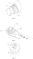
- An oral hygiene device comprises the replacement brush head of any of the above-mentioned embodiments, a magnetic electroplated iron block 2 and a handle 8, and the handle is provided therein with a handle transmission shaft 81, the handle transmission shaft 81 is connected to the replacement brush head in a transmission manner through the magnetic electroplated iron block 2.
- the replacement brush head and oral hygiene device converts a linear motion of the transmission shaft device into a rotary motion, effectively controlling the rotation angle and swing frequency of the brush head, realizing the smooth transmission of the brush head, and meanwhile reducing the noise caused by the transmission process, and has the technical effect of convenient, fast and low-cost assembly.
- the present invention provides a replacement brush head, as shown in FIGs. 1-2 , comprising: a bristle head 5, a housing 6, a transmission shaft 3 and a tail cover 1, the transmission shaft 3 is arranged inside the housing 6, and the bristle head 5 is arranged in a transmission manner at a top end of the housing 6 through the transmission shaft 3, and the tail cover 1 is arranged at a tail end of the housing 6.
- the transmission shaft 3 includes a transmission rod 30, a top end of the transmission rod 30 is provided with a transmission convex column 32, and the transmission rod 30 is provided with a cross guide groove 31, a damping spring 4 is sheathed on the transmission rod 30, and preferably, a guide rib 61 and a spring limiting rib 62 are provided on an inner side of the housing 6.
- the cross guide groove 31 of the transmission shaft and the guide rib 61 inside the outer cover prevent the transmission shaft from deflecting during its front-back reciprocating movement inside the replacement brush head, such that the transmission process is more stable.
- the damping spring 4 sheathed on the transmission shaft 3, when the transmission shaft is assembled into the housing, the damping spring is in a compressed state due to the spring limiting rib 62 on an inner wall of the housing, so that the transmission shaft body is suspended inside the housing, and the transmission shaft will not collide with the inner wall of the housing during its high-frequency front-back movement, which can effectively reduce noise and make the transmission more stable.
- the damping spring 4 can effectively reduce the inertial kinetic energy generated by the high-frequency front-back transmission of the transmission shaft, and convert the kinetic energy into elastic potential energy, resulting in more stable transmission, effectively reducing the transmission noise, reducing the wear between the transmission shaft and the bristle head due to long-term transmission, and improving the service life.
- a tail end of the transmission rod 30 is composed of a peripheral wall and a cavity formed by the peripheral wall, and a plane limiter 36 is provided on an outer side of the peripheral wall, and an assembly positioning groove 35 is provided on an outer side surface adjacent to the plane limiter 36.
- the plane limiter 36 and the assembly positioning groove 35 at the tail of the transmission shaft, enable automatic production of the assembly process, improve production efficiency and reduce production cost.
- a convex point 11 and a circle of ribs 15 are arranged on a middle wall of the tail cover body, which cause the tail cover to tightly fit with the housing.
- An elastic damping arm 13 on the tail cover realizes a better damping feel during a long-term replacement and pull-plug process of the handle 8 and the replacement brush head, so that the handle 8 and the replacement brush head fit more tightly.
- a front end of the elastic damping arm 13 is provided with a boss 14, and a recess 12 at a bottom of the tail cover and the boss 14 ensure that there will be no left-right offset during the assembly process of the tail cover and the housing, and after the assembly, there will be no misalignment and the fit is more tightly, and the tail cover position and the housing position are effectively prevented from rotating.
- the entire oral hygiene device is ensured to be in the working state, the internal transmission is stable and does not shake, the use is more stable, and the replacement brush head housing remains stationary in the oral cavity, and only the bristle part of the brush head rotates, reducing transmission noise and improving user experience.
- the outer wall of the tail cover 1 is provided with a convex point 11 and a rib 15 on one side, and an elastic damping arm 13 and the boss 14 on the opposite side, and a recess 12 is provided at the bottom end of the tail cover 1.
- the top end of the housing 6 is provided with a bristle head defining rib 64, a bristle head positioning column 63 and a fixing hole 65 at a connection with the bristle head 5.
- the bottom step of the bristle head 5 is provided with a central hole 51 and an eccentric transmission hole 52, a side of the step is provided with a limiting groove 53, and the bristle head is provided with soft bristles 54.
- the central hole 51 of the bottom step of the bristle head is assembled with the positioning column 63 of the housing, so that the bristle head rotates and reciprocates around the positioning column 63 in the working state.
- the eccentric transmission hole 52 is assembled with the transmission convex column 32 of the transmission shaft, so that the front-back reciprocating motion of the transmission shaft is converted into a rotary motion through the transmission of an eccentric shaft.
- a fixing nail 7 is inserted into the limiting groove 53 of the bristle head 5 through the fixing hole 65 of the housing, so that the bristle head does not jump during the swing working process and the transmission is more stable.
- the transmission convex column 32 at a front end of the transmission shaft cooperates with the eccentric transmission hole 52 of the bristle head to assemble the bristle head on the housing, and the transmission shaft drives the bristle head to rotate, thereby achieving the effect of cleaning the oral cavity.
- This embodiment also provides an oral hygiene device, as shown in FIG. 11 , comprising the replacement brush head of any of the above-mentioned embodiments, a magnetic electroplated iron block 2 and a handle 8, and the handle is provided therein with a handle transmission shaft 81, the handle transmission shaft 81 is connected to the replacement brush head in a transmission manner through the magnetic electroplated iron block 2.
- the transmission shaft is assembled with a magnetic electroplated iron block 2, as shown in FIGs. 1-2 , and after the handle is assembled with the replacement brush head, the magnetic electroplated iron block 2 connects the handle transmission shaft 81 on the handle to the transmission shaft in a transmission manner, thereby driving the bristle head to swing.
- a glue dispensing port 33 and a glue overflow groove 34 on the peripheral wall are configured such that the magnetic electroplated iron block 2 more stably arranged in the cavity at a tail end of the transmission shaft, and further, the magnetic electroplated iron block 2 and the transmission shaft are more closely connected to prevent the transmission shaft from falling off during transmission or generating abnormal noise due to assembly clearance.
- the oral hygiene device converts the linear motion of the transmission shaft device into the rotary motion, effectively controlling the rotation angle and swing frequency of the brush head, realizing the smooth transmission of the brush head, and meanwhile reducing the noise caused by the transmission process, and has the technical effect of convenient, fast and low-cost assembly.
Landscapes
- Health & Medical Sciences (AREA)
- Dentistry (AREA)
- Epidemiology (AREA)
- Life Sciences & Earth Sciences (AREA)
- Animal Behavior & Ethology (AREA)
- General Health & Medical Sciences (AREA)
- Public Health (AREA)
- Veterinary Medicine (AREA)
- Brushes (AREA)
Applications Claiming Priority (1)
| Application Number | Priority Date | Filing Date | Title |
|---|---|---|---|
| CN202220621513.4U CN217525467U (zh) | 2022-03-22 | 2022-03-22 | 一种替换刷头及口腔卫生装置 |
Publications (4)
| Publication Number | Publication Date |
|---|---|
| EP4248909A2 true EP4248909A2 (de) | 2023-09-27 |
| EP4248909A3 EP4248909A3 (de) | 2023-11-29 |
| EP4248909B1 EP4248909B1 (de) | 2026-02-25 |
| EP4248909C0 EP4248909C0 (de) | 2026-02-25 |
Family
ID=83427895
Family Applications (1)
| Application Number | Title | Priority Date | Filing Date |
|---|---|---|---|
| EP23162575.7A Active EP4248909B1 (de) | 2022-03-22 | 2023-03-17 | Ersatzbürstenkopf und mundhygienevorrichtung |
Country Status (2)
| Country | Link |
|---|---|
| EP (1) | EP4248909B1 (de) |
| CN (1) | CN217525467U (de) |
Cited By (1)
| Publication number | Priority date | Publication date | Assignee | Title |
|---|---|---|---|---|
| US12036079B2 (en) | 2022-01-31 | 2024-07-16 | Braun Gmbh | Attachment for an oral care device handle |
Families Citing this family (1)
| Publication number | Priority date | Publication date | Assignee | Title |
|---|---|---|---|---|
| CN114557788A (zh) * | 2022-03-22 | 2022-05-31 | 深圳市雅贝康科技有限公司 | 一种替换刷头及口腔卫生装置 |
Family Cites Families (2)
| Publication number | Priority date | Publication date | Assignee | Title |
|---|---|---|---|---|
| US20040049868A1 (en) * | 2002-09-13 | 2004-03-18 | Ng Wai Fun | Electric toothbrush with 3-dimensional brush head movements |
| PL2550937T3 (pl) * | 2011-07-25 | 2014-07-31 | Braun Gmbh | Magnetyczne połączenie pomiędzy uchwytem szczoteczki do zębów i główką szczoteczki do zębów |
-
2022
- 2022-03-22 CN CN202220621513.4U patent/CN217525467U/zh not_active Ceased
-
2023
- 2023-03-17 EP EP23162575.7A patent/EP4248909B1/de active Active
Cited By (2)
| Publication number | Priority date | Publication date | Assignee | Title |
|---|---|---|---|---|
| US12036079B2 (en) | 2022-01-31 | 2024-07-16 | Braun Gmbh | Attachment for an oral care device handle |
| US12440321B2 (en) | 2022-01-31 | 2025-10-14 | Braun Gmbh | Attachment for an oral care device handle |
Also Published As
| Publication number | Publication date |
|---|---|
| EP4248909A3 (de) | 2023-11-29 |
| EP4248909B1 (de) | 2026-02-25 |
| EP4248909C0 (de) | 2026-02-25 |
| CN217525467U (zh) | 2022-10-04 |
Similar Documents
| Publication | Publication Date | Title |
|---|---|---|
| US12303019B2 (en) | Replacement brush head and oral hygiene device | |
| EP4248909A2 (de) | Ersatzbürstenkopf und mundhygienevorrichtung | |
| US6447293B1 (en) | Drive mechanism for interproximal flossing device | |
| US8336155B2 (en) | Replacement head for electric toothbrush | |
| US10952833B2 (en) | Spring mechanism for power device | |
| CN1306915C (zh) | 电动牙刷 | |
| EP4467098A2 (de) | Rotierende ersatzkopfvorrichtung für elektrische zahnbürste | |
| JP4596891B2 (ja) | 電動歯ブラシ | |
| KR200499647Y1 (ko) | 전동 칫솔 회전 교체 헤드 장치 | |
| CN218922846U (zh) | 一种牙刷头及电动牙刷 | |
| US20050008986A1 (en) | Multi-directional motion flosser | |
| WO2026067251A1 (zh) | 一种刷头及电动牙刷 | |
| CN106901857B (zh) | 一种拉拽式电动牙刷的驱动机构 | |
| US20220168084A1 (en) | Drive mechanism for power device | |
| US11903782B1 (en) | Electric toothbrush connecting member and electric toothbrush | |
| CN113440293A (zh) | 一种左右旋转的电动牙刷 | |
| US12186149B1 (en) | Electric toothbrush head | |
| RU223863U1 (ru) | Узел вращающейся головки для электрической зубной щетки | |
| CN221866084U (zh) | 电动口腔清洁工具 | |
| CN223586067U (zh) | 牙刷头及电动牙刷 | |
| CN222676515U (zh) | 清洁组件和传动结构 | |
| JP3253298U (ja) | 電動歯ブラシ | |
| CN204723206U (zh) | 一种电动牙刷 | |
| CN217137711U (zh) | 一种多功能食品加工机 | |
| CN220706159U (zh) | 一种电动牙刷头连接结构 |
Legal Events
| Date | Code | Title | Description |
|---|---|---|---|
| PUAI | Public reference made under article 153(3) epc to a published international application that has entered the european phase |
Free format text: ORIGINAL CODE: 0009012 |
|
| STAA | Information on the status of an ep patent application or granted ep patent |
Free format text: STATUS: REQUEST FOR EXAMINATION WAS MADE |
|
| 17P | Request for examination filed |
Effective date: 20230317 |
|
| AK | Designated contracting states |
Kind code of ref document: A2 Designated state(s): AL AT BE BG CH CY CZ DE DK EE ES FI FR GB GR HR HU IE IS IT LI LT LU LV MC ME MK MT NL NO PL PT RO RS SE SI SK SM TR |
|
| PUAL | Search report despatched |
Free format text: ORIGINAL CODE: 0009013 |
|
| AK | Designated contracting states |
Kind code of ref document: A3 Designated state(s): AL AT BE BG CH CY CZ DE DK EE ES FI FR GB GR HR HU IE IS IT LI LT LU LV MC ME MK MT NL NO PL PT RO RS SE SI SK SM TR |
|
| RIC1 | Information provided on ipc code assigned before grant |
Ipc: A61C 17/34 20060101ALI20231020BHEP Ipc: A61C 17/22 20060101AFI20231020BHEP |
|
| STAA | Information on the status of an ep patent application or granted ep patent |
Free format text: STATUS: EXAMINATION IS IN PROGRESS |
|
| 17Q | First examination report despatched |
Effective date: 20241010 |
|
| GRAP | Despatch of communication of intention to grant a patent |
Free format text: ORIGINAL CODE: EPIDOSNIGR1 |
|
| STAA | Information on the status of an ep patent application or granted ep patent |
Free format text: STATUS: GRANT OF PATENT IS INTENDED |
|
| INTG | Intention to grant announced |
Effective date: 20251127 |
|
| GRAS | Grant fee paid |
Free format text: ORIGINAL CODE: EPIDOSNIGR3 |
|
| GRAA | (expected) grant |
Free format text: ORIGINAL CODE: 0009210 |
|
| STAA | Information on the status of an ep patent application or granted ep patent |
Free format text: STATUS: THE PATENT HAS BEEN GRANTED |
|
| AK | Designated contracting states |
Kind code of ref document: B1 Designated state(s): AL AT BE BG CH CY CZ DE DK EE ES FI FR GB GR HR HU IE IS IT LI LT LU LV MC ME MK MT NL NO PL PT RO RS SE SI SK SM TR |
|
| REG | Reference to a national code |
Ref country code: CH Ref legal event code: F10 Free format text: ST27 STATUS EVENT CODE: U-0-0-F10-F00 (AS PROVIDED BY THE NATIONAL OFFICE) Effective date: 20260225 Ref country code: GB Ref legal event code: FG4D |
|
| REG | Reference to a national code |
Ref country code: DE Ref legal event code: R096 Ref document number: 602023012409 Country of ref document: DE |
|
| REG | Reference to a national code |
Ref country code: IE Ref legal event code: FG4D |
|
| PGFP | Annual fee paid to national office [announced via postgrant information from national office to epo] |
Ref country code: AT Payment date: 20260301 Year of fee payment: 4 |
|
| U01 | Request for unitary effect filed |
Effective date: 20260316 |
|
| U07 | Unitary effect registered |
Designated state(s): AT BE BG DE DK EE FI FR IT LT LU LV MT NL PT RO SE SI Effective date: 20260320 |