EP4248059B1 - Verbesserungen in bezug auf unterbodenheizgeräte und verfahren zum betrieb solcher - Google Patents
Verbesserungen in bezug auf unterbodenheizgeräte und verfahren zum betrieb solcher Download PDFInfo
- Publication number
- EP4248059B1 EP4248059B1 EP21815638.8A EP21815638A EP4248059B1 EP 4248059 B1 EP4248059 B1 EP 4248059B1 EP 21815638 A EP21815638 A EP 21815638A EP 4248059 B1 EP4248059 B1 EP 4248059B1
- Authority
- EP
- European Patent Office
- Prior art keywords
- deflector
- alloy
- downhole
- tubular body
- annular seal
- Prior art date
- Legal status (The legal status is an assumption and is not a legal conclusion. Google has not performed a legal analysis and makes no representation as to the accuracy of the status listed.)
- Active
Links
Images


Classifications
-
- E—FIXED CONSTRUCTIONS
- E21—EARTH OR ROCK DRILLING; MINING
- E21B—EARTH OR ROCK DRILLING; OBTAINING OIL, GAS, WATER, SOLUBLE OR MELTABLE MATERIALS OR A SLURRY OF MINERALS FROM WELLS
- E21B33/00—Sealing or packing boreholes or wells
- E21B33/10—Sealing or packing boreholes or wells in the borehole
- E21B33/13—Methods or devices for cementing, for plugging holes, crevices or the like
-
- E—FIXED CONSTRUCTIONS
- E21—EARTH OR ROCK DRILLING; MINING
- E21B—EARTH OR ROCK DRILLING; OBTAINING OIL, GAS, WATER, SOLUBLE OR MELTABLE MATERIALS OR A SLURRY OF MINERALS FROM WELLS
- E21B29/00—Cutting or destroying pipes, packers, plugs or wire lines, located in boreholes or wells, e.g. cutting of damaged pipes, of windows; Deforming of pipes in boreholes or wells; Reconditioning of well casings while in the ground
- E21B29/02—Cutting or destroying pipes, packers, plugs or wire lines, located in boreholes or wells, e.g. cutting of damaged pipes, of windows; Deforming of pipes in boreholes or wells; Reconditioning of well casings while in the ground by explosives or by thermal or chemical means
-
- E—FIXED CONSTRUCTIONS
- E21—EARTH OR ROCK DRILLING; MINING
- E21B—EARTH OR ROCK DRILLING; OBTAINING OIL, GAS, WATER, SOLUBLE OR MELTABLE MATERIALS OR A SLURRY OF MINERALS FROM WELLS
- E21B31/00—Fishing for or freeing objects in boreholes or wells
- E21B31/08—Fishing for or freeing objects in boreholes or wells using junk baskets or the like
-
- E—FIXED CONSTRUCTIONS
- E21—EARTH OR ROCK DRILLING; MINING
- E21B—EARTH OR ROCK DRILLING; OBTAINING OIL, GAS, WATER, SOLUBLE OR MELTABLE MATERIALS OR A SLURRY OF MINERALS FROM WELLS
- E21B33/00—Sealing or packing boreholes or wells
- E21B33/10—Sealing or packing boreholes or wells in the borehole
- E21B33/12—Packers; Plugs
- E21B33/128—Packers; Plugs with a member expanded radially by axial pressure
-
- E—FIXED CONSTRUCTIONS
- E21—EARTH OR ROCK DRILLING; MINING
- E21B—EARTH OR ROCK DRILLING; OBTAINING OIL, GAS, WATER, SOLUBLE OR MELTABLE MATERIALS OR A SLURRY OF MINERALS FROM WELLS
- E21B36/00—Heating, cooling or insulating arrangements for boreholes or wells, e.g. for use in permafrost zones
- E21B36/008—Heating, cooling or insulating arrangements for boreholes or wells, e.g. for use in permafrost zones using chemical heat generating means
-
- E—FIXED CONSTRUCTIONS
- E21—EARTH OR ROCK DRILLING; MINING
- E21B—EARTH OR ROCK DRILLING; OBTAINING OIL, GAS, WATER, SOLUBLE OR MELTABLE MATERIALS OR A SLURRY OF MINERALS FROM WELLS
- E21B29/00—Cutting or destroying pipes, packers, plugs or wire lines, located in boreholes or wells, e.g. cutting of damaged pipes, of windows; Deforming of pipes in boreholes or wells; Reconditioning of well casings while in the ground
Definitions
- the present invention relates to the technical field of downhole operations in oil/gas wellbores, and in particular to remedial operations associated with repairing faults in annular seals, such as annular packers and cement seals, found within oil/gas wellbores.
- Additional tubing in the form of well lining or well casing, may also be deployed in locations where the underground formation is unstable and needs to be held back to maintain the integrity of the oil/gas well.
- US 2018/0003001 A1 relates to an apparatus and a method for repairing a leaking annular seal located within an annulus that encircles an oil/gas wellbore tubular body.
- the present invention seeks to provide an alternative approach to repairing leaks that may have developed in an existing annular seal that is located in an annular space encircling a tubular body within an oil/gas wellbore.
- Typical annular seals include cement seals and annular packers.
- the invention is defined by claims 1 and 9; other aspects of the invention are given in the dependent claims 2 to 8 and 10 to 18.
- a method of repairing a leaking annular seal located within an annulus that encircles an oil/gas wellbore tubular body comprising: deploying a heating tool comprising at least one heater downhole via the tubular body to a downhole target region that is proximal to the annular seal; positioning a deflector in the downhole target region so that the deflector is up-hole of the annular seal and the heating tool and down-hole of a portion of the tubular body wall that comprises one or more openings; delivering alloy beads to the downhole target region via the tubular body such that the deflector redirects the alloy beads radially outwards towards said one or more openings and into the annulus, wherein the alloy beads accumulate on top of the annular seal; and operating said heating tool to increase the temperature within the downhole target region to a temperature that is sufficient to melt the alloy beads accumulated within the annulus before allowing the molten alloy to cool and form an alloy plug that repairs the leaking annul
- the annular seal being repaired may comprise an annular packer and/or a cement seal.
- 'up-hole' and 'down-hole' used herein are intended to denote the relative positioning of the various elements present in the wellbore. That is to say, 'up-hole' denotes that a first element is closer to the surface of the wellbore than a second element, (i.e. the first element is located between the surface and the second element).
- 'down-hole' denotes that the first element is further away from the surface of the wellbore than the second element (i.e. the second element is located between the surface and the first element).
- the method of the present invention utilises the innermost wellbore tubular body to achieve the majority of the alloy's journey to a downhole target region. In this way it is possible to make use of the cleaner internal diameter of the innermost tubular body, which typically has less restrictions than the annulus not least due to the absence of couplings that project into the annulus.
- alloy beads that are deployed down the annulus can land on the upper surfaces of the couplings and in so doing be prevented from reaching the downhole target region.
- the loss of alloy beads in transit due to obstructions within the annulus can be significant over the full distance from the surface to the target region.
- the passage of the alloy (which is provided in the form of beads, balls or shot) through the wall of the innermost tubular body into the annulus is achieved via one or more openings provided in the tubular body at a location that is up-hole of the annular seal.
- pre-existing openings include valves, such as: sliding sleeve valves, gas lift mandrel valves, and pressure diverter subs.
- valves such as: sliding sleeve valves, gas lift mandrel valves, and pressure diverter subs.
- hole making equipment may be employed to create one or more openings in the tubular body.
- the method employs a deflector that is also delivered downhole via the tubular body to a location that is down-hole of said one or more openings.
- the positioning and configuration of the deflector is such that when the alloy beads are deployed within the tubular body they contact the deflector and are redirected radially outwards towards said one or more openings and out into the annulus, wherein the alloy beads accumulate on top of the up-hole face of the annular seal.
- a heating tool which is also deployed downhole via the tubular body, is operated to increase the temperature within the target region to a level that is sufficient to melt the alloy beads. Following the operation of the heating tool the molten alloy is allowed to cool, wherein the alloy solidifies within the annulus as an alloy plug that effectively repairs any leaks within the annular seal.
- the method of the present invention is considered particularly suitable for use in a single trip annular seal repair. That is to say, the various stages of the repair method can be achieved using a single annular seal repair assembly that is deployed downhole via the tubular body only once.
- the heating tool can be deployed to any location that is within heating range of the up-hole face of the annular seal, preferably said heating tool is deployed to a location within the wellbore tubular body that is proximal to and up-hole of the annular seal.
- the heating tool comprises multiple heaters that are operated independently to provide heat at different times. This use of multiple, independently controllable heaters provides the operator with much greater control of the heating levels within the downhole target region.
- said heaters are independently operated to: a) commence generating heat before the heating tool reaches the downhole target region; b) pre-heat the alloy beads before they are redirected into the annulus by the deflector; c) pre-heat the downhole target region before the alloy beads are accumulated on top of the annular seal; d) provide the alloy melting temperature within the downhole target region after the alloy beads have begun to accumulate on top of the annular seal; and/or e) provide the alloy melting temperature within the downhole target region once the alloy beads have accumulated on top of the annular seal.
- the heating tool and the deflector are provided as an annular seal repair tool assembly that is deployed downhole via a common delivery support that is connected to delivery means located above-ground at the surface of the wellbore.
- annular seal repair tool assembly that combines all of the main tools required to carry out the main steps of the repair method facilitates the formation of an alloy plug within the annulus in a single trip.
- Achieving the deployment of an alloy plug using a single combined assembly has the potential to speed up the repair process by avoiding the need for deploying and retrieving a different tool for each step of the method.
- the single trip approach thereby offers cost efficiencies as a result of the quicker repair times and the need for fewer downhole tool deployments.
- the common delivery support used to deploy the annular seal repair tool downhole may be selected from: coiled tubing, pipe, slick line and wireline.
- the delivery of the alloy beads may be achieved by dumping the alloy beads into the wellbore tubular body from a location above-ground at the surface of the wellbore.
- This approach has the benefit of being relatively low cost, because the alloy beads are simply dropped into the innermost tubular body.
- the delivery of the alloy beads may be achieved by a dump bailer deployed downhole via the tubular body, said dump bailer forming part of the annular seal repair tool assembly.
- This approach has the benefit of providing a more controlled deployment of the alloy beads onto the deflector.
- the delivery of the alloy beads may be achieved via the coiled tubing or pipe that is used to deploy the annular seal repair tool assembly downhole.
- this approach provides a more controlled deployment of the alloy beads onto the deflector.
- the method of the present invention makes use of pre-existing openings in the well bore tubular body to facilitate the passage of the alloy beads from within the tubular body to the surrounding annulus.
- the method may preferably further comprise forming one or more openings in the portion of the tubular body wall that is located up-hole from the annular seal, wherein said one or more openings are formed prior to the delivery of the alloy beads using a hole making tool that forms part of the annular seal repair tool assembly.
- the downhole target region may be agitated in order to assist the passage of the alloy beads through said one or more openings into the annulus.
- the deflector is vibrated to agitate the downhole target region.
- the tubular body is vibrated to agitate the downhole target region.
- the deflector will also act to reduce the flow of heating fluids upwards within the tubular body and in so doing reduce the amount of heat being lost from the downhole target region. Reducing heat loss in this way also helps to make more efficient use of the heating tool.
- the deflector may comprise insulating means configured to restrict the passage of conducted heat through the deflector.
- the deflector not only acts to reduce the amount of heat lost as a result of heated fluids rising within the tubular body, but is also prevents heat being transferred across the deflector via a process of conduction.
- the deflector may be deployed downhole in an unexpanded or partially expanded state and then expanded towards the tubular body wall in the downhole target region so as to increase the extent to which the deflector redirects the alloy beads. It is appreciated that expanding the deflector in this way will also further restrict the upward flow of heating fluids within the wellbore.
- the deflector is easier to deliver downhole in situations of restricted access (e.g. when the tubular body is of smaller diameter and/or the tubular body has one or more obstructions within it).
- the heating tool comprises one or more chemical reaction heaters.
- the chemical reaction heaters preferably employ thermite or thermite based mixes for the generation of heat that is suitable to melt the alloy beads.
- the alloy beads are provided in the form of a low melting alloy that has melting point of less than 300°C.
- These low melting alloys are sometimes also referred to as fusible alloys.
- the alloy beads may be provided in the form of bismuth based alloys. It is envisioned that the bismuth based alloys may be eutectic or non-eutectic in nature and may also qualify as low melting alloys.
- the present invention provides a downhole annular seal repair tool assembly for use in forming an alloy plug on an existing annular seal that substantially encircles an oil/gas wellbore tubular body, said assembly comprising: a delivery support connection point, by which the assembly is connectable to delivery means via a delivery support such that the assembly can be delivered to and retrieved from a downhole target region of the wellbore via the tubular body; a heating tool having at least one heater, said heating tool configured to increase the temperature within the downhole target region to temperature that is sufficient to melt alloy beads accumulated within the annulus so as to enable the formation of the alloy plug on the existing annular seal; and a deflector arranged up-hole of said heating tool, wherein the deflector is configured to obstruct alloy beads delivered downhole and redirect them radially outwards towards the walls of the wellbore tubular body.
- the assembly can be used to deliver the annular seal repair method of the present invention in a single trip. That is to say, all of the components needed to carry out the steps of the described repair method are either provided by the assembly or otherwise present without the need to retrieve the assembly and deploy a second tool downhole.
- the present invention is considered particularly suitable for repairing leaks in annular cement seals and annular packers.
- the heating tool may comprise multiple heaters that are independently controlled. In this way each of the heaters can be operated in unison at the same time or separately according to a predetermined sequence.
- the deflector comprises an up-hole facing surface that comprises at least one sloped region.
- the alloy beads hit the deflector they are re-directed radially outwards towards the wall of the tubular body in which said one or more openings are located.
- the up-hole facing surface of the deflector is cone-shaped or domed. Further, the apex of the cone or the dome is preferably located on a central axis running through the deflector.
- the assembly may further comprise an agitation mechanism configured to agitate and/or vibrate the downhole target region of the wellbore.
- an agitation mechanism configured to agitate and/or vibrate the downhole target region of the wellbore.
- agitating the downhole target region helps to prevent the alloy beads from becoming jammed in said one or more openings in the tubular body wall, which would otherwise prevent the alloy beads from passing through into the annulus.
- the agitation mechanism is configured to vibrate the deflector.
- the agitation mechanism is configured to vibrate the tubular body within the downhole target region of the wellbore.
- the deflector may be configured to be expandable radially outwards towards the tubular body wall. In this way the deflector can be delivered downhole in a smaller form and then, once in position, increased in size to make it more effective at re-directing the alloy beads.
- the mechanism by which the expansion of the deflector is achieved is selected from hydraulic means, pneumatic means, mechanical means and combinations thereof.
- the deflector may preferably be urged to expand and/or contract by way of one or more resilient biasing means. Further preferably the deflector may comprise a canopy of flexible material connected to an umbrella spring mechanism.
- the deflector may comprise insulating means configured to restrict the passage of conducted heat through the deflector.
- insulating means configured to restrict the passage of conducted heat through the deflector.
- the assembly may further comprise a delivery support selected from: coiled tubing, pipe, slick line and wireline.
- a delivery support selected from: coiled tubing, pipe, slick line and wireline.
- such delivery supports are configured to deliver alloy beads to the downhole target region of the wellbore.
- the alloy beads can be delivered onto the deflector via the same coiled tubing/pipe that is used to deploy the deflector and the heating tool.
- the assembly may further comprise alloy bead delivery means in the form of a dump bailer arranged up-hole of the deflector and said heating tool.
- alloy beads can be delivered downhole on-board the assembly and then, once the deflector is in position adjacent to said one or more openings in the wall of the tubular body, released onto the deflector.
- alloy beads may also be simply dumped onto the deflector from a location at the surface of the wellbore. In such situations neither the dump bailer nor the specific delivery supports are essential.
- tubular body wall does not include suitable openings to facilitate the passage of the alloy beads out of the tubular body into the annulus, it is envisioned that it will be necessary to form openings in the wall of the tubular body before the alloy beads are deployed.
- assembly of the present invention preferably further comprises hole making equipment configured to form one or more opening in the walls of the wellbore tubular body.
- the hole making equipment is preferably selected from: a drill, a mechanical punch, a perforating gun, a saw or any other suitable cutting tools such as chemical cutters and fluid jet cutters.
- the assembly may further comprise a junk basket positioned at a leading end of the assembly.
- a junk basket positioned at a leading end of the assembly.
- the junk basket is considered particularly useful for catching any alloy beads that are not re-directed into the annulus by the deflector. With that said, another material that might be caught is the swarf created by the operation of the hole making equipment.
- the heating tool may comprise one or more chemical reaction heaters.
- the chemical reaction heaters preferably employ thermite or thermite based mixes for the generation of heat that is suitable to melt the alloy beads.
- each embodiment employs an annular seal repair tool assembly that comprises the core components of a heating tool and a deflector, wherein the deflector is located up-hole of the heating tool.
- the annular seal repair tool assembly shown in each embodiment comprises certain other preferable components.
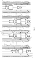
- Figure 1 shows the application of the annular seal repair method of the present invention in a wellbore target region where only a single annulus is present.
- the annulus 3 is defined by the outer casing 1 and the inner tubular body 2.
- an annular packer 4 Within the annulus 3 is provided an annular packer 4.
- the annular packer 4 shown in Figure 1 has a fault line which is causing the packer 4 to leak, hence the application of the annular seal repair method.
- the wellbore tubular body 2 has pre-openings 5 in the tubing wall of the inner tubular body. It is envisioned that the pre-existing holes may be the result of a previous downhole operation or could be provided by components already present on the tubular body 2; such as valves (e.g. sliding sleeve valves, gas lift mandrel valves, and pressure diverter subs).
- valves e.g. sliding sleeve valves, gas lift mandrel valves, and pressure diverter subs.
- annular seal repair tool assembly 6 is delivered downhole and brought into close proximity with the pre-existing openings 5.
- the annular seal repair tool assembly 6 comprises a heating tool 7 that is located at the leading end of the assembly 6 at a position down-hole of a deflector 8.
- the annular seal repair tool assembly 6 is deployed downhole using a common delivery support that is connected to delivery means located above-ground at the surface of the wellbore.
- the delivery means are not shown in Figure 1 , but it will be appreciated by the skilled person that standard delivery means can be utilised to achieve the deployment of the assembly 6 to the downhole target region in which the openings 5 are located.
- delivery support is not shown in any detail, it will be appreciated that suitable types of delivery support include coiled tubing, pipe, slick line and wireline. It is appreciated that any combination of delivery support and delivery means can be employed provided it facilitates the controlled deployment of the annular seal repair tool assembly 6 to the downhole target region via the interior of the tubular body 2.
- the deflector 8 which is located down-hole of the openings 5, is expanded so that is extends radially outwards towards the surrounding wall of the tubular body 2.
- the expansion of the deflector 8 can be achieved by way of hydraulic means, pneumatic means, mechanical means and combinations thereof.
- the expansion of the deflector 8 towards the wall of the tubular body 2 greatly reduces the possibility that alloy beads 9 will fall past the assembly 6 without coming into contact with the deflector 8.
- alloy beads 9 are delivered to the downhole target region.
- the alloy beads are delivered by a process of dumping the alloy beads into the wellbore tubular body 2 at the surface of the wellbore above ground (not shown).
- dumped alloy beads 9 fall down the wellbore via the inner tubular body until they come into contact with the deflector 8, at which point they are re-directed radially outward towards the openings 5 in the wellbore tubular body 2 and out into the annulus 3.
- the alloy beads 9 then accumulate on the up-hole surface of the annular packer 4.
- the alloy beads can be formed from any alloy, provided the alloy melts at a temperature above that found within the downhole environment (e.g. around 5 to 50°C). This is important because it enables the alloy to form a stable solid plug within the annulus.
- the alloy beads 9 are formed from a low melting alloy that has a melting point that is no more than about 300°C and which further preferably comprises bismuth.
- Bismuth is preferred component because it its alloys tend to contract upon melting and expand upon re-solidification, which is considered beneficial when forming alloy plugs.
- the alloy beads will have a diameter in the range of 0.76 to 127mm (about 0.030 to 0.5 inches). However, ultimately the size of the beads will be determined by the openings in the tubular body wall and any other restrictions that might exist because the alloy beads must be able to pass downhole and through the openings into the annulus with relative freedom.
- the deflector 8 has an upper face that is dome-shaped such that alloy beads striking the deflector are re-directed radially outward. It is appreciated that the upper surface of the deflector may comprise different shapes, ranging from cone-shaped to single flat sloped faces, and that any face shapes that help re-direct the alloy beads towards the tubular body wall are preferable.
- the upper face of the deflector it is not considered essential for the upper face of the deflector to be sloped because the process of redirecting the alloy beads towards the wall of the tubular body could also be achieved by agitating the downhole target region to help shake the alloy beads through the openings and into the annulus (see Figure 3 ).
- heating tool 7 shown in Figure 1 comprises only a single heater, it is envisaged that the heating tool 7 may comprise multiple individually operable heaters. Employing multiple heaters in this way provides the option to operate the heaters sequentially or in unison to achieve different heating programs.
- one possible heating program might employ a first heater to preheat but not necessarily melt the alloy beads before they are deployed onto the deflector. Once the pre-heated alloy beads have been delivered to the annulus via the deflector a second heater could be operated to ensure complete melting of the alloy. This is considered particularly beneficial in the downhole environments where there is a significant difference between the ambient temperature in the target region and the melting point of the alloy.
- the heating tool 7 comprises a single heater that is operated once the whole load of alloy beads has been delivered to the annulus 3.
- the heating tool comprises at least one chemical heater that generates heat from a thermite based reaction.
- the molten alloy is allowed to cool and as it does the alloy resolidifies on top of the existing annular packer 4 to form a plug 10 which acts to seal any fissures/cracks in the packer.
- the annular seal repair tool assembly 6 can be retrieved from the wellbore using the common delivery support and the above-ground delivery means.
- the downhole target region shown in Figure 2 comprises two annuli.
- the first annulus is defined by the outer casing 1 and the intermediate well tubing 2a and the second annulus 3 is defined by the intermediate well tubing 2a and the wellbore tubular body 2.
- the failing annular packer 4 is provided in the second annulus.
- annular seal repair tool assembly 11 employed in this embodiment of the repair method is provided with an alternative construction to that shown in Figure 1 . With that said, the heating tool 7 and the deflector (albeit in a different form 12) are maintained in the assembly 11.
- annular seal repair tool assembly 11 comprises a heating tool 7 with a deflector mounted above it in an up-hole location.
- hole making equipment 13 is provided up-hole of both the heating tool and the deflector.
- the hole making equipment 13 is in the form of a perforation gun.
- suitable types of hole making equipment that might alternatively be employed to form the required openings in the wall of the tubular body 2 include a drill, a mechanical punch, a saw or indeed any other suitable cutting tools such as chemical cutters.
- a junk basket 14 At the leading end of the assembly 11, below the rest of the assembly's components is provided a junk basket 14.
- the junk basket is configured to be expandable towards the tubular body wall so as to maximise its ability to capture any materials that fall past the assembly 11 during the operation of the repair method.
- the assembly is delivered down hole to the downhole target region.
- the delivery can be achieved using a range of common support devices and above-ground delivery means.
- the comments made regarding the delivery of the annular seal repair tool assembly of Figure 1 also apply to the assembly shown in Figure 2 .
- the positioning of the assembly 11 in the first stage is such that, when the hole making equipment is operated, the one or more openings 15 that are formed in a portion of the tubular body wall that is located up-hole of the annular packer 4.
- the assembly 11 can be partially raised back up the wellbore by the delivery means until the deflector 12 is positioned adjacent (albeit slightly down hole) the openings 15 ready for the second stage of the method.
- alloy beads 9 are delivered to the downhole target region via the tubular body 2. As before, the alloy beads 9 are dumped downhole from dumping means located at the surface of the wellbore.
- the alloy beads 9 descend the wellbore within the tubular body and those that strike the deflector 12 are re-directed towards the openings 15 and out into the annulus 3, where they accumulate on the up-hole face of the annular packer 4.
- the deflector 12 employed in the assembly 11 shown in Figure 2 is not expandable. As a result, some of the alloy beads 9 miss the deflector and continue to descend past the heating tool 7. In such situations the alloy beads 9 that are not redirected into the annulus 3 are caught by the junk basket 14 located at the leading end of the assembly 11.
- the heating tool 7 is operated to heat the downhole target region to a temperature that is sufficient to melt the alloy beads 9. Once melted, the alloy beads are allowed to cool and re-solidify to form an alloy plug 10 within the annulus 3, which sits on top of the annular packer 4 and seals any leaks therein.
- the annular seal repair tool assembly 11 can then be retrieved from the wellbore using the above-ground delivery means.
- Figure 3 show a third preferred embodiment of the annular seal repair method of the present invention.
- the downhole target region comprises two annuli.
- the inner wellbore tubular body 2 is provided with pre-existing openings 5. It will be appreciated that if the openings were not present, or were unsuitable to facilitate the passage of the alloy beads from the tubular body to the annulus, hole making equipment could be employed on the annular seal repair tool assembly 20.
- the annular seal repair tool assembly 20 employed in the method shown in Figure 3 comprises a heating tool 7 with a deflector mounted to it in an up-hole location. It is appreciated that the clearance between the heating tool 7 and the deflector 22 can range from 0 to 20 metres. This preferred range is applicable to all of the embodiments described herein.
- the deflector 22 provided on the assembly employed in the method shown in Figure 3 does not have a sloped upper face. Instead the deflector is provided with agitation means that are configured to shake the alloy beads towards the openings 5 and into the annulus 3.
- the deflector 22 shown in Figure 3 is configured to be expandable radially outwards towards the tubular body wall; possibility in a manner similar to than achieved by a bridge plug.
- the deflector may comprise heat insulating means that are configured to minimise the passage of heat through the deflector 22.
- the deflector can serve a dual purpose of achieving alloy bead re-direction and also lowering the amount of heat lost from the downhole target region due to the upward flow of heated wellbore fluids.
- the assembly 20 is provided with a dump bailer 21.
- the dump bailer 21 is located up-hole of both the deflector 22 and the heating tool 7.
- the dump bailer is used to deliver the alloy beads down hole with the assembly so that the alloy can be deployed locally onto the deflector rather than by dumping the alloy from the surface of the wellbore.
- the dump bailer 21 can be operated and the alloy beads can be deployed onto the upper face of the deflector 22. Although some of the alloy beads will naturally pass through the openings 5, the redirection of the majority of the alloy beads will be achieved by the application of an agitating force within the downhole target region.
- the agitation force is provided by vibrating the deflector 22 to shake the alloy beads through the openings 5.
- the tubular body may also be agitated either alone or in combination with the deflector to assist the re-direction of the alloy beads towards the openings in the wall of the tubular body and into the annulus.
- the deflectors are being either shaped (e.g. domed-shaped, cone-shaped) so as to re-direct alloy beads towards the openings or subject to vibrations to agitate the alloy beads, it is envisioned that both approaches may be used in concert to facilitate efficient re-direction of the alloy beads into the annulus 3.
- the heating tool is operated to melt the alloy within the annulus.
- the molten alloy is left to cool and re-solidify to form an alloy plug within the annulus on top of the existing annular packer.
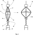
- Figure 4 shows a partial view of a preferred embodiment of the annular seal repair tool assembly 30 of the present invention in both an unexpanded state and an expanded state in which the deflector extends beyond the outer diameter of the heating tool 32.
- the heater 11, of which only the uppermost portion is shown, is provided with a setting tool 33 that essentially houses the control mechanisms for operating the heater (e.g. ignition means in the case of a chemical heater).
- a setting tool 33 that essentially houses the control mechanisms for operating the heater (e.g. ignition means in the case of a chemical heater).
- the setting tool is then connected via a delivery support connection point 34 to a delivery support, which is shown as a wireline 35 but could be any suitable connection line, pipe or coil.
- the deflector 31 is located between the connection point 34 and the setting tool 33 of the heater 32.
- the deflector 31 comprises a central shaft 36 that is connected between the setting tool 33 of the heater 32 and the delivery support connection point 34.
- a collar 37 is fixed in position on the shaft 36. Attached to the collar 37 is a web of flexible material 38 that essentially forms a canopy that is capable of changing shape to accommodate the expansion and contraction of the deflector 31.
- the flexible material should be resistant to the downhole environment within which the assembly 30 is to be deployed. It is envisaged that a suitable flexible material for use in the deflector is a heat resistant canvas or a silicone rubber. However the skilled person will appreciate that other flexible materials could suitably be employed.
- the deflector 31 further comprises a plurality of resiliently biased expansion bands 40 that are secured at their respective ends to the connection point 34 and a moveable collar 39, which is slidably mounted on the central shaft 36. In this way the unsecured middle portions of the bands are free to bend and flex in a radial direction relative to the central shaft.
- resiliently biased expansion bands 40 may be formed from flexible strips of a suitable spring metal.
- an alternative resilient material may be employed without departing from the scope of the present invention.
- the moveable collar 39 is urged away from the setting tool 33 by way of actuation means 41, which may take the form of a coiled spring. It is envisaged that the actuation means 41 can be used to control the distance between the connection point 34 and the collar 39, which in turn will control the extent to which the resiliently biased expansion bands 40 can be deformed.
- actuation means 41 can limit the extent to which the collar 39 can move up and down the central shaft, which in turn limits the extent to which deflector 31 can be expanded or contracted.
- the central portion of the canopy of flexible material 38 is attached to the fixed collar 37 whilst the periphery of the canopy is attached to each of the plurality of resiliently biased expansion bands 40.
- the deflector By connecting the flexible material to the middle portions of the resiliently biased expansion bands 40, the deflector can be operated to expand and contract the flexible material so that the extent to which it can deflect the alloy beads is varied and also restrict the flow of fluid past the deflector.
- the resiliently biased expansion bands 40 When the resiliently biased expansion bands 40 are forced radially outwards they pull the flexible material outwards to form an expanded blocking structure that may extend across a large portion, if not all, of the inner diameter of the wellbore tubular body. Also, when the resiliently biased expansion bands 40 move radially inwards they pull in the flexible material and contract the deflector 31.
- the bands 40 will extend outwards beyond the outer diameter of the rest of the heater assembly 32 so that the canopy of flexible material will at least partially block the borehole and, in so doing, restrict the flow of fluids within the borehole.
- the flexible nature of the bands allows the deflector to compress, as necessary, to accommodate narrowed portions of the borehole that might be encountered during the annular seal repair tool assembly's deployment. Once past the narrowed portion of a borehole, the resilient nature of the bands will cause the baffle to once again return to its expanded state, in which the deflector restricts the movement of alloy beads and fluid within the wellbore tubular body.
- the canopy may be caused to expand even further under the influence of heated fluids rising within the borehole. That is rising fluid could become trapped by partially opened canopy and then urge it to open further.
- the actuation means 41 may be operated to force moveable collar 39 to slide up the shaft 36, thereby urging the resiliently biased expansion bands 40 outwards and opening the canopy.
Landscapes
- Life Sciences & Earth Sciences (AREA)
- Geology (AREA)
- Engineering & Computer Science (AREA)
- Mining & Mineral Resources (AREA)
- Geochemistry & Mineralogy (AREA)
- Fluid Mechanics (AREA)
- Environmental & Geological Engineering (AREA)
- General Life Sciences & Earth Sciences (AREA)
- Physics & Mathematics (AREA)
- Marine Sciences & Fisheries (AREA)
- Chemical & Material Sciences (AREA)
- Chemical Kinetics & Catalysis (AREA)
- General Chemical & Material Sciences (AREA)
- Earth Drilling (AREA)
- Pipe Accessories (AREA)
- Gasket Seals (AREA)
Claims (18)
- Verfahren zum Reparieren einer undichten ringförmigen Dichtung (4), die sich innerhalb eines Ringraums (3) befindet, der einen Öl-/Gasbohrlochrohrkörper (2) umschließt, wobei das Verfahren umfasst:Einbringen eines Heizwerkzeugs (7, 32) umfassend mindestens ein Heizelement lochabwärts über den Rohrkörper in einen lochabwärtigen Zielbereich, der nahe und vorzugsweise lochaufwärts der ringförmigen Dichtung (4) ist;Positionieren eines Deflektors (8, 12, 22, 31) in dem lochabwärtigen Zielbereich, so dass der Deflektor lochabwärts eines Abschnitts der Rohrkörperwand ist, der eine oder mehrere Öffnungen (5) umfasst;Zuführen von Legierungskügelchen (9) zu dem lochabwärtigen Zielbereich über den Rohrkörper (2), so dass der Deflektor (8, 12, 22, 31) die Legierungskügelchen (9) radial nach außen hin zu der einen oder mehreren Öffnungen (5) und in den Ringraum (3) umleitet, wobei sich die Legierungskügelchen auf der Oberseite der ringförmigen Dichtung (4) ansammeln; undBetreiben des Heizwerkzeugs (7, 32), um die Temperatur innerhalb des lochabwärtigen Zielbereichs auf eine Temperatur zu erhöhen, die ausreicht, um die innerhalb des Ringraums (3) angesammelten Legierungskügelchen (9) zu schmelzen, bevor die geschmolzene Legierung abkühlen und einen Legierungsstopfen (10) bilden kann, der die undichte ringförmige Dichtung (4) repariert; undgekennzeichnet durch Positionieren des Deflektors (8, 12, 22, 31) in dem lochabwärtigen Zielbereich, so dass der Deflektor lochaufwärts der ringförmigen Dichtung (4) und des Heizwerkzeugs (7, 32) ist.
- Verfahren nach Anspruch 1, wobei das Heizwerkzeug (7, 32) mehrere Heizelemente umfasst, die unabhängig betrieben werden, um zu unterschiedlichen Zeiten Wärme bereitzustellen; wobei vorzugsweise die Heizelemente unabhängig betrieben werden zum:a) Beginnen mit der Wärmeerzeugung, bevor das Heizwerkzeug (7, 32) den lochabwärtigen Zielbereich erreicht;b) Vorwärmen der Legierungskügelchen (9), bevor sie durch den Deflektor (8, 12, 22, 31) in den Ringraum (3) umgeleitet werden;c) Vorwärmen des lochabwärtigen Zielbereichs, bevor die Legierungskügelchen (9) oben auf der ringförmigen Dichtung (4) angesammelt werden;d) Bereitstellen der Legierungsschmelztemperatur innerhalb des lochabwärtigen Zielbereichs, nachdem die Legierungskügelchen (9) begonnen haben, sich oben auf der ringförmigen Dichtung (4) anzusammeln; und/odere) Bereitstellen der Legierungsschmelztemperatur innerhalb des lochabwärtigen Zielbereichs, sobald sich die Legierungskügelchen (9) oben auf der ringförmigen Dichtung (4) angesammelt haben.
- Verfahren nach einem der Ansprüche 1 bis 2, wobei das Heizwerkzeug (7, 32) und der Deflektor (8, 12, 22, 31) als eine Ringdichtungs-Reparaturwerkzeuganordnung (6, 11, 20, 30) bereitgestellt werden, die lochabwärts über einen gemeinsamen Zuführungsträger eingebracht wird, der mit Zuführungsmitteln verbunden ist, die sich über Tage an der Oberfläche des Bohrlochs befinden; und
wobei vorzugsweise der gemeinsame Zuführungsträger, der verwendet wird, um die Ringdichtungs-Reparaturwerkzeuganordnung lochabwärts einzubringen, ausgewählt ist aus: Rohrschlange, Rohr, Gleitleitung und Drahtleitung. - Verfahren nach einem der Ansprüche 1 bis 3, wobei die Zuführung der Legierungskügelchen (9) erreicht wird durch entweder:a) Kippen der Legierungskügelchen (9) in den Bohrlochrohrkörper (2) von einer Stelle über Tage an der Oberfläche des Bohrlochs;b) einen Kipper (21), der lochabwärts über den Rohrkörper (2) eingebracht wird, wobei der Kipper Bestandteil der Ringdichtungs-Reparaturwerkzeuganordnung (20) ist; oderc) die Rohrschlange oder das Rohr, die/das verwendet wird, um die Ringdichtungs-Reparaturwerkzeuganordnung lochabwärts einzubringen.
- Verfahren nach einem der vorhergehenden Ansprüche, ferner umfassend das Bilden einer oder mehrerer Öffnungen (5) in dem Abschnitt der Rohrkörperwand, der sich lochaufwärts der ringförmigen Dichtung (4) befindet, wobei die eine oder mehreren Öffnungen vor der Zuführung der Legierungskügelchen (9) unter Verwendung eines Lochherstellungswerkzeugs gebildet werden, das Bestandteil der Ringdichtungs-Reparaturwerkzeuganordnung (11) ist.
- Verfahren nach einem der vorhergehenden Ansprüche, wobei der lochabwärtige Zielbereich agitiert wird, um den Durchgang der Legierungskügelchen (9) durch die eine oder mehreren Öffnungen (5) in den Ringraum (3) zu unterstützen;
wobei vorzugsweise der Deflektor (8, 12, 22, 31) und/oder der Rohrkörper (2) vibriert wird, um den lochabwärtigen Zielbereich zu agitieren. - Verfahren nach einem der vorhergehenden Ansprüche, wobei der Deflektor (8, 12, 22, 31) Isolierungsmittel umfasst, die dazu konfiguriert sind, den Durchgang von geleiteter Wärme durch den Deflektor einzuschränken; und/oder
der Deflektor (8, 22, 31) lochabwärts in einem nicht expandierten oder teilweise expandierten Zustand eingebracht und dann hin zu der Rohrkörperwand in dem lochabwärtigen Zielbereich expandiert wird, um so das Ausmaß zu erhöhen, in dem der Deflektor die Legierungskügelchen (9) umleitet. - Verfahren nach einem der vorhergehenden Ansprüche, wobei die Legierungskügelchen (9) in Form einer niedrigschmelzenden Legierung bereitgestellt werden, die einen Schmelzpunkt von weniger als 300 °C aufweist; und wobei vorzugsweise die Legierungskügelchen in Form einer wismutbasierten Legierung bereitgestellt werden.
- Lochabwärtige Ringdichtungs-Reparaturwerkzeuganordnung (6, 11, 20, 30) zur Verwendung beim Bilden eines Legierungsstopfens (10) auf einer existierenden ringförmigen Dichtung (4), die im Wesentlichen einen Öl-/Gasbohrlochrohrkörper (2) umschließt, wobei die Anordnung umfasst:einen Zuführungsträger-Verbindungspunkt, durch den die Anordnung über einen Zuführungsträger mit Zuführungsmitteln verbindbar ist, so dass die Anordnung über den Rohrkörper (2) einem lochabwärtigen Zielbereich des Bohrlochs zugeführt und aus diesem herausgeholt werden kann;ein Heizwerkzeug (7, 32) mit mindestens einem Heizelement, wobei das Heizwerkzeug dazu konfiguriert ist, die Temperatur innerhalb des lochabwärtigen Zielbereichs auf eine Temperatur zu erhöhen, die ausreicht, um innerhalb des Ringraums (3) angesammelte Legierungskügelchen (9) zu schmelzen, um so die Bildung des Legierungsstopfens (10) auf der existierenden ringförmigen Dichtung (4) zu ermöglichen; undgekennzeichnet durch einen Deflektor (8, 12, 22, 31), der lochaufwärts des Heizwerkzeugs (7, 32) angeordnet ist, wobei der Deflektor konfiguriert ist zum Blockieren von Legierungskügelchen (9), die lochabwärts zugeführt werden, und deren Umleitung radial nach außen hin zu den Wänden des Bohrlochrohrkörpers.
- Anordnung nach Anspruch 9, wobei das Heizwerkzeug (7, 32) mehrere Heizelemente umfasst, die unabhängig gesteuert werden.
- Anordnung nach Anspruch 9 oder 10, wobei der Deflektor (8, 12, 31) eine lochaufwärts weisende Oberfläche umfasst, die mindestens einen geneigten Bereich umfasst; und
wobei vorzugsweise die lochaufwärts weisende Oberfläche des Deflektors kegelförmig ist und vorzugsweise die Spitze des Kegels an der zentralen Achse des Deflektors befindlich ist. - Anordnung nach einem der Ansprüche 9 bis 11, ferner umfassend einen Agitationsmechanismus, der dazu konfiguriert ist, den lochabwärtigen Zielbereich in dem Bohrloch zu agitieren und/oder zu vibrieren;
wobei vorzugsweise der Agitationsmechanismus dazu konfiguriert ist, den Deflektor (8, 12, 22, 31) und/oder den Rohrkörper (2) innerhalb des lochabwärtigen Zielbereichs des Bohrlochs zu vibrieren. - Anordnung nach einem der Ansprüche 9 bis 12, wobei der Deflektor (8, 22, 31) dazu konfiguriert ist, radial nach außen hin zu der Rohrkörperwand expandierbar zu sein;wobei vorzugsweise der Mechanismus, durch den die Expansion des Deflektors erreicht wird, aus hydraulischen Mitteln, pneumatischen Mitteln, mechanischen Mitteln und Kombinationen davon ausgewählt ist;wobei der ferner vorzugsweise Deflektor mittels eines oder mehrerer elastischer Vorspannmittel zum Expandieren und/oder Kontrahieren gebracht wird; undwobei noch weiter bevorzugt der Deflektor (31) eine Abdeckung aus flexiblem Material (38) umfasst, die mit einem Schirmfedermechanismus (40) verbunden ist.
- Anordnung nach einem der Ansprüche 9 bis 13, wobei der Deflektor (8, 12, 22, 31) Isolierungsmittel umfasst, die dazu konfiguriert sind, den Durchgang von geleiteter Wärme durch den Deflektor zu begrenzen.
- Anordnung nach einem der Ansprüche 9 bis 14, ferner umfassend einen Zuführungsträger, der ausgewählt ist aus: Rohrschlange, Rohr, Gleitleitung und Drahtleitung;
wobei vorzugsweise der Zuführungsträger entweder eine Rohrschlange oder ein Rohr und somit dazu konfiguriert ist, dem lochabwärtigen Zielbereich des Bohrlochs Legierungskügelchen zuzuführen. - Anordnung nach einem der Ansprüche 9 bis 14, ferner umfassend Legierungskügelchen-Zuführungsmittel in Form eines Kippers (21), der lochaufwärts des Deflektors (22) und des Heizwerkzeugs (7) angeordnet ist.
- Anordnung nach einem der Ansprüche 9 bis 16, ferner umfassend Lochherstellungsausrüstung (13), die dazu konfiguriert ist, eine oder mehrere Öffnungen in den Wänden des Bohrlochrohrkörpers zu bilden;
wobei vorzugsweise die Lochherstellungsausrüstung ausgewählt ist aus: einem Bohrer, einer mechanischen Stanze, einer Perforierpistole, einer Säge oder beliebigen anderen geeigneten Schneidwerkzeugen wie z. B. chemischen Schneidvorrichtungen und Fluidstrahlschneidvorrichtungen. - Anordnung nach einem der Ansprüche 9 bis 17, ferner umfassend einen Abfallkorb (14), der an einem vorderen Ende der Anordnung positioniert ist.
Applications Claiming Priority (3)
| Application Number | Priority Date | Filing Date | Title |
|---|---|---|---|
| GB2018390.1A GB2601185B (en) | 2020-11-23 | 2020-11-23 | Improvements relating to downhole heater assemblies and methods of operating such |
| GB2111408.7A GB2603561B (en) | 2020-11-23 | 2021-08-06 | Single trip annular seal repair method and associated equipment |
| PCT/GB2021/053017 WO2022106848A1 (en) | 2020-11-23 | 2021-11-22 | Single trip annular seal repair method and associated equipment |
Publications (2)
| Publication Number | Publication Date |
|---|---|
| EP4248059A1 EP4248059A1 (de) | 2023-09-27 |
| EP4248059B1 true EP4248059B1 (de) | 2025-02-19 |
Family
ID=78806557
Family Applications (1)
| Application Number | Title | Priority Date | Filing Date |
|---|---|---|---|
| EP21815638.8A Active EP4248059B1 (de) | 2020-11-23 | 2021-11-22 | Verbesserungen in bezug auf unterbodenheizgeräte und verfahren zum betrieb solcher |
Country Status (5)
| Country | Link |
|---|---|
| US (1) | US20230417121A1 (de) |
| EP (1) | EP4248059B1 (de) |
| AU (1) | AU2021382394A1 (de) |
| DK (1) | DK4248059T3 (de) |
| WO (1) | WO2022106848A1 (de) |
Families Citing this family (3)
| Publication number | Priority date | Publication date | Assignee | Title |
|---|---|---|---|---|
| GB202112492D0 (en) * | 2021-09-02 | 2021-10-20 | Head Philip | All metal-to-metal casing patch |
| US12338713B2 (en) * | 2022-09-07 | 2025-06-24 | Bisn Tec Ltd. | One trip system to set an alloy seal and mill through |
| US12264550B1 (en) | 2023-09-29 | 2025-04-01 | Halliburton Energy Services, Inc. | Downhole tool for sealing in openhole washouts |
Family Cites Families (3)
| Publication number | Priority date | Publication date | Assignee | Title |
|---|---|---|---|---|
| US6384389B1 (en) | 2000-03-30 | 2002-05-07 | Tesla Industries Inc. | Eutectic metal sealing method and apparatus for oil and gas wells |
| US10597970B2 (en) * | 2015-01-27 | 2020-03-24 | Schlumberger Technology Corporation | Downhole cutting and sealing apparatus |
| GB2586759B (en) * | 2018-04-03 | 2022-09-28 | Schlumberger Technology Bv | Methods, apparatus and systems for creating wellbore plugs for abandoned wells |
-
2021
- 2021-11-22 DK DK21815638.8T patent/DK4248059T3/da active
- 2021-11-22 WO PCT/GB2021/053017 patent/WO2022106848A1/en not_active Ceased
- 2021-11-22 AU AU2021382394A patent/AU2021382394A1/en active Pending
- 2021-11-22 US US18/038,204 patent/US20230417121A1/en active Pending
- 2021-11-22 EP EP21815638.8A patent/EP4248059B1/de active Active
Also Published As
| Publication number | Publication date |
|---|---|
| DK4248059T3 (da) | 2025-05-12 |
| US20230417121A1 (en) | 2023-12-28 |
| EP4248059A1 (de) | 2023-09-27 |
| AU2021382394A1 (en) | 2023-06-29 |
| WO2022106848A1 (en) | 2022-05-27 |
| AU2021382394A9 (en) | 2025-01-16 |
Similar Documents
| Publication | Publication Date | Title |
|---|---|---|
| US12359528B2 (en) | Expandable eutectic alloy based downhole tool and methods of deploying such | |
| US11525329B2 (en) | Apparatus for use in well abandonment | |
| EP4248060B1 (de) | Verbesserungen in bezug auf unterbodenheizgeräte und verfahren zum betrieb solcher | |
| US20230417121A1 (en) | Single trip annular seal repair method and associated equipment | |
| EP3455450B1 (de) | Schutz eines verbrauchsartikelpackerelements für verbesserte einlaufzeiten | |
| US20200256165A1 (en) | Expandable liner | |
| GB2603561A (en) | Single trip annular seal repair method and associated equipment | |
| WO2016023864A1 (en) | Assembly and method for creating an expanded tubular element in a borehole | |
| WO2020031010A1 (en) | Centralizer having atmospheric chamber for expansion in response to hydrostatic pressure | |
| EP4506535A1 (de) | Bohrlochabschlusssystem | |
| EP1381750B1 (de) | Bohrvorrichtung mit expandierbarer hülse | |
| US11885191B2 (en) | Patch for joining downhole ends of pipes | |
| EP4359638B1 (de) | Im bohrloch fräsbarer permanentstopfen und verfahren zum setzen eines im bohrloch fräsbaren permanentstopfens | |
| GB2608269A (en) | An expandable eutectic alloy based downhole tool and methods of deploying such |
Legal Events
| Date | Code | Title | Description |
|---|---|---|---|
| STAA | Information on the status of an ep patent application or granted ep patent |
Free format text: STATUS: UNKNOWN |
|
| STAA | Information on the status of an ep patent application or granted ep patent |
Free format text: STATUS: THE INTERNATIONAL PUBLICATION HAS BEEN MADE |
|
| PUAI | Public reference made under article 153(3) epc to a published international application that has entered the european phase |
Free format text: ORIGINAL CODE: 0009012 |
|
| STAA | Information on the status of an ep patent application or granted ep patent |
Free format text: STATUS: REQUEST FOR EXAMINATION WAS MADE |
|
| 17P | Request for examination filed |
Effective date: 20230612 |
|
| AK | Designated contracting states |
Kind code of ref document: A1 Designated state(s): AL AT BE BG CH CY CZ DE DK EE ES FI FR GB GR HR HU IE IS IT LI LT LU LV MC MK MT NL NO PL PT RO RS SE SI SK SM TR |
|
| DAV | Request for validation of the european patent (deleted) | ||
| DAX | Request for extension of the european patent (deleted) | ||
| GRAP | Despatch of communication of intention to grant a patent |
Free format text: ORIGINAL CODE: EPIDOSNIGR1 |
|
| STAA | Information on the status of an ep patent application or granted ep patent |
Free format text: STATUS: GRANT OF PATENT IS INTENDED |
|
| INTG | Intention to grant announced |
Effective date: 20240424 |
|
| GRAJ | Information related to disapproval of communication of intention to grant by the applicant or resumption of examination proceedings by the epo deleted |
Free format text: ORIGINAL CODE: EPIDOSDIGR1 |
|
| STAA | Information on the status of an ep patent application or granted ep patent |
Free format text: STATUS: REQUEST FOR EXAMINATION WAS MADE |
|
| GRAP | Despatch of communication of intention to grant a patent |
Free format text: ORIGINAL CODE: EPIDOSNIGR1 |
|
| STAA | Information on the status of an ep patent application or granted ep patent |
Free format text: STATUS: GRANT OF PATENT IS INTENDED |
|
| INTC | Intention to grant announced (deleted) | ||
| INTG | Intention to grant announced |
Effective date: 20240910 |
|
| GRAS | Grant fee paid |
Free format text: ORIGINAL CODE: EPIDOSNIGR3 |
|
| GRAA | (expected) grant |
Free format text: ORIGINAL CODE: 0009210 |
|
| STAA | Information on the status of an ep patent application or granted ep patent |
Free format text: STATUS: THE PATENT HAS BEEN GRANTED |
|
| RBV | Designated contracting states (corrected) |
Designated state(s): AL AT BE BG CH CY CZ DE DK EE ES FI FR GR HR HU IE IS IT LI LT LU LV MC MK MT NL NO PL PT RO RS SE SI SK SM TR |
|
| RIN1 | Information on inventor provided before grant (corrected) |
Inventor name: TALAPATRA, DIDHITI Inventor name: DEARMON, JAKE Inventor name: CARRAGHER, PAUL |
|
| AK | Designated contracting states |
Kind code of ref document: B1 Designated state(s): AL AT BE BG CH CY CZ DE DK EE ES FI FR GR HR HU IE IS IT LI LT LU LV MC MK MT NL NO PL PT RO RS SE SI SK SM TR |
|
| REG | Reference to a national code |
Ref country code: CH Ref legal event code: EP |
|
| REG | Reference to a national code |
Ref country code: IE Ref legal event code: FG4D |
|
| REG | Reference to a national code |
Ref country code: DE Ref legal event code: R096 Ref document number: 602021026475 Country of ref document: DE |
|
| REG | Reference to a national code |
Ref country code: DK Ref legal event code: T3 Effective date: 20250506 |
|
| REG | Reference to a national code |
Ref country code: NL Ref legal event code: MP Effective date: 20250219 |
|
| PG25 | Lapsed in a contracting state [announced via postgrant information from national office to epo] |
Ref country code: RS Free format text: LAPSE BECAUSE OF FAILURE TO SUBMIT A TRANSLATION OF THE DESCRIPTION OR TO PAY THE FEE WITHIN THE PRESCRIBED TIME-LIMIT Effective date: 20250519 |
|
| PG25 | Lapsed in a contracting state [announced via postgrant information from national office to epo] |
Ref country code: FI Free format text: LAPSE BECAUSE OF FAILURE TO SUBMIT A TRANSLATION OF THE DESCRIPTION OR TO PAY THE FEE WITHIN THE PRESCRIBED TIME-LIMIT Effective date: 20250219 |
|
| PG25 | Lapsed in a contracting state [announced via postgrant information from national office to epo] |
Ref country code: PL Free format text: LAPSE BECAUSE OF FAILURE TO SUBMIT A TRANSLATION OF THE DESCRIPTION OR TO PAY THE FEE WITHIN THE PRESCRIBED TIME-LIMIT Effective date: 20250219 |
|
| PG25 | Lapsed in a contracting state [announced via postgrant information from national office to epo] |
Ref country code: ES Free format text: LAPSE BECAUSE OF FAILURE TO SUBMIT A TRANSLATION OF THE DESCRIPTION OR TO PAY THE FEE WITHIN THE PRESCRIBED TIME-LIMIT Effective date: 20250219 |
|
| REG | Reference to a national code |
Ref country code: LT Ref legal event code: MG9D |
|
| PG25 | Lapsed in a contracting state [announced via postgrant information from national office to epo] |
Ref country code: IS Free format text: LAPSE BECAUSE OF FAILURE TO SUBMIT A TRANSLATION OF THE DESCRIPTION OR TO PAY THE FEE WITHIN THE PRESCRIBED TIME-LIMIT Effective date: 20250619 |
|
| PG25 | Lapsed in a contracting state [announced via postgrant information from national office to epo] |
Ref country code: NL Free format text: LAPSE BECAUSE OF FAILURE TO SUBMIT A TRANSLATION OF THE DESCRIPTION OR TO PAY THE FEE WITHIN THE PRESCRIBED TIME-LIMIT Effective date: 20250219 |
|
| PG25 | Lapsed in a contracting state [announced via postgrant information from national office to epo] |
Ref country code: HR Free format text: LAPSE BECAUSE OF FAILURE TO SUBMIT A TRANSLATION OF THE DESCRIPTION OR TO PAY THE FEE WITHIN THE PRESCRIBED TIME-LIMIT Effective date: 20250219 |
|
| PG25 | Lapsed in a contracting state [announced via postgrant information from national office to epo] |
Ref country code: PT Free format text: LAPSE BECAUSE OF FAILURE TO SUBMIT A TRANSLATION OF THE DESCRIPTION OR TO PAY THE FEE WITHIN THE PRESCRIBED TIME-LIMIT Effective date: 20250620 Ref country code: LV Free format text: LAPSE BECAUSE OF FAILURE TO SUBMIT A TRANSLATION OF THE DESCRIPTION OR TO PAY THE FEE WITHIN THE PRESCRIBED TIME-LIMIT Effective date: 20250219 |
|
| PG25 | Lapsed in a contracting state [announced via postgrant information from national office to epo] |
Ref country code: BG Free format text: LAPSE BECAUSE OF FAILURE TO SUBMIT A TRANSLATION OF THE DESCRIPTION OR TO PAY THE FEE WITHIN THE PRESCRIBED TIME-LIMIT Effective date: 20250219 Ref country code: GR Free format text: LAPSE BECAUSE OF FAILURE TO SUBMIT A TRANSLATION OF THE DESCRIPTION OR TO PAY THE FEE WITHIN THE PRESCRIBED TIME-LIMIT Effective date: 20250520 |
|
| REG | Reference to a national code |
Ref country code: AT Ref legal event code: MK05 Ref document number: 1768435 Country of ref document: AT Kind code of ref document: T Effective date: 20250219 |
|
| PG25 | Lapsed in a contracting state [announced via postgrant information from national office to epo] |
Ref country code: SE Free format text: LAPSE BECAUSE OF FAILURE TO SUBMIT A TRANSLATION OF THE DESCRIPTION OR TO PAY THE FEE WITHIN THE PRESCRIBED TIME-LIMIT Effective date: 20250219 |
|
| PG25 | Lapsed in a contracting state [announced via postgrant information from national office to epo] |
Ref country code: SM Free format text: LAPSE BECAUSE OF FAILURE TO SUBMIT A TRANSLATION OF THE DESCRIPTION OR TO PAY THE FEE WITHIN THE PRESCRIBED TIME-LIMIT Effective date: 20250219 |
|
| PG25 | Lapsed in a contracting state [announced via postgrant information from national office to epo] |
Ref country code: IT Free format text: LAPSE BECAUSE OF FAILURE TO SUBMIT A TRANSLATION OF THE DESCRIPTION OR TO PAY THE FEE WITHIN THE PRESCRIBED TIME-LIMIT Effective date: 20250219 |
|
| PG25 | Lapsed in a contracting state [announced via postgrant information from national office to epo] |
Ref country code: AT Free format text: LAPSE BECAUSE OF FAILURE TO SUBMIT A TRANSLATION OF THE DESCRIPTION OR TO PAY THE FEE WITHIN THE PRESCRIBED TIME-LIMIT Effective date: 20250219 |
|
| PG25 | Lapsed in a contracting state [announced via postgrant information from national office to epo] |
Ref country code: EE Free format text: LAPSE BECAUSE OF FAILURE TO SUBMIT A TRANSLATION OF THE DESCRIPTION OR TO PAY THE FEE WITHIN THE PRESCRIBED TIME-LIMIT Effective date: 20250219 Ref country code: CZ Free format text: LAPSE BECAUSE OF FAILURE TO SUBMIT A TRANSLATION OF THE DESCRIPTION OR TO PAY THE FEE WITHIN THE PRESCRIBED TIME-LIMIT Effective date: 20250219 |
|
| PG25 | Lapsed in a contracting state [announced via postgrant information from national office to epo] |
Ref country code: RO Free format text: LAPSE BECAUSE OF FAILURE TO SUBMIT A TRANSLATION OF THE DESCRIPTION OR TO PAY THE FEE WITHIN THE PRESCRIBED TIME-LIMIT Effective date: 20250219 |
|
| PG25 | Lapsed in a contracting state [announced via postgrant information from national office to epo] |
Ref country code: SK Free format text: LAPSE BECAUSE OF FAILURE TO SUBMIT A TRANSLATION OF THE DESCRIPTION OR TO PAY THE FEE WITHIN THE PRESCRIBED TIME-LIMIT Effective date: 20250219 |
|
| REG | Reference to a national code |
Ref country code: DE Ref legal event code: R097 Ref document number: 602021026475 Country of ref document: DE |
|
| PLBE | No opposition filed within time limit |
Free format text: ORIGINAL CODE: 0009261 |
|
| STAA | Information on the status of an ep patent application or granted ep patent |
Free format text: STATUS: NO OPPOSITION FILED WITHIN TIME LIMIT |
|
| PGFP | Annual fee paid to national office [announced via postgrant information from national office to epo] |
Ref country code: NO Payment date: 20251125 Year of fee payment: 5 |
|
| PGFP | Annual fee paid to national office [announced via postgrant information from national office to epo] |
Ref country code: DK Payment date: 20251125 Year of fee payment: 5 |
|
| 26N | No opposition filed |
Effective date: 20251120 |