EP4247708B1 - Elektrisch angetriebener motor - Google Patents
Elektrisch angetriebener motor Download PDFInfo
- Publication number
- EP4247708B1 EP4247708B1 EP21816024.0A EP21816024A EP4247708B1 EP 4247708 B1 EP4247708 B1 EP 4247708B1 EP 21816024 A EP21816024 A EP 21816024A EP 4247708 B1 EP4247708 B1 EP 4247708B1
- Authority
- EP
- European Patent Office
- Prior art keywords
- rotor
- electrically powered
- fan engine
- powered fan
- rim
- Prior art date
- Legal status (The legal status is an assumption and is not a legal conclusion. Google has not performed a legal analysis and makes no representation as to the accuracy of the status listed.)
- Active
Links
Images


Classifications
-
- B—PERFORMING OPERATIONS; TRANSPORTING
- B64—AIRCRAFT; AVIATION; COSMONAUTICS
- B64D—EQUIPMENT FOR FITTING IN OR TO AIRCRAFT; FLIGHT SUITS; PARACHUTES; ARRANGEMENT OR MOUNTING OF POWER PLANTS OR PROPULSION TRANSMISSIONS IN AIRCRAFT
- B64D27/00—Arrangement or mounting of power plants in aircraft; Aircraft characterised by the type or position of power plants
- B64D27/02—Aircraft characterised by the type or position of power plants
- B64D27/24—Aircraft characterised by the type or position of power plants using steam or spring force
-
- B—PERFORMING OPERATIONS; TRANSPORTING
- B64—AIRCRAFT; AVIATION; COSMONAUTICS
- B64C—AEROPLANES; HELICOPTERS
- B64C11/00—Propellers, e.g. of ducted type; Features common to propellers and rotors for rotorcraft
- B64C11/001—Shrouded propellers
-
- B—PERFORMING OPERATIONS; TRANSPORTING
- B64—AIRCRAFT; AVIATION; COSMONAUTICS
- B64C—AEROPLANES; HELICOPTERS
- B64C11/00—Propellers, e.g. of ducted type; Features common to propellers and rotors for rotorcraft
-
- B—PERFORMING OPERATIONS; TRANSPORTING
- B64—AIRCRAFT; AVIATION; COSMONAUTICS
- B64C—AEROPLANES; HELICOPTERS
- B64C11/00—Propellers, e.g. of ducted type; Features common to propellers and rotors for rotorcraft
- B64C11/46—Arrangements of, or constructional features peculiar to, multiple propellers
- B64C11/48—Units of two or more coaxial propellers
-
- H—ELECTRICITY
- H02—GENERATION; CONVERSION OR DISTRIBUTION OF ELECTRIC POWER
- H02K—DYNAMO-ELECTRIC MACHINES
- H02K1/00—Details of the magnetic circuit
- H02K1/06—Details of the magnetic circuit characterised by the shape, form or construction
- H02K1/22—Rotating parts of the magnetic circuit
- H02K1/27—Rotor cores with permanent magnets
- H02K1/2706—Inner rotors
-
- H—ELECTRICITY
- H02—GENERATION; CONVERSION OR DISTRIBUTION OF ELECTRIC POWER
- H02K—DYNAMO-ELECTRIC MACHINES
- H02K1/00—Details of the magnetic circuit
- H02K1/06—Details of the magnetic circuit characterised by the shape, form or construction
- H02K1/22—Rotating parts of the magnetic circuit
- H02K1/32—Rotating parts of the magnetic circuit with channels or ducts for flow of cooling medium
-
- H—ELECTRICITY
- H02—GENERATION; CONVERSION OR DISTRIBUTION OF ELECTRIC POWER
- H02K—DYNAMO-ELECTRIC MACHINES
- H02K16/00—Machines with more than one rotor or stator
- H02K16/02—Machines with one stator and two or more rotors
-
- H—ELECTRICITY
- H02—GENERATION; CONVERSION OR DISTRIBUTION OF ELECTRIC POWER
- H02K—DYNAMO-ELECTRIC MACHINES
- H02K7/00—Arrangements for handling mechanical energy structurally associated with dynamo-electric machines, e.g. structural association with mechanical driving motors or auxiliary dynamo-electric machines
- H02K7/006—Structural association of a motor or generator with the drive train of a motor vehicle
-
- B—PERFORMING OPERATIONS; TRANSPORTING
- B64—AIRCRAFT; AVIATION; COSMONAUTICS
- B64D—EQUIPMENT FOR FITTING IN OR TO AIRCRAFT; FLIGHT SUITS; PARACHUTES; ARRANGEMENT OR MOUNTING OF POWER PLANTS OR PROPULSION TRANSMISSIONS IN AIRCRAFT
- B64D27/00—Arrangement or mounting of power plants in aircraft; Aircraft characterised by the type or position of power plants
- B64D27/02—Aircraft characterised by the type or position of power plants
- B64D27/30—Aircraft characterised by electric power plants
- B64D27/34—All-electric aircraft
-
- Y—GENERAL TAGGING OF NEW TECHNOLOGICAL DEVELOPMENTS; GENERAL TAGGING OF CROSS-SECTIONAL TECHNOLOGIES SPANNING OVER SEVERAL SECTIONS OF THE IPC; TECHNICAL SUBJECTS COVERED BY FORMER USPC CROSS-REFERENCE ART COLLECTIONS [XRACs] AND DIGESTS
- Y02—TECHNOLOGIES OR APPLICATIONS FOR MITIGATION OR ADAPTATION AGAINST CLIMATE CHANGE
- Y02T—CLIMATE CHANGE MITIGATION TECHNOLOGIES RELATED TO TRANSPORTATION
- Y02T50/00—Aeronautics or air transport
- Y02T50/60—Efficient propulsion technologies, e.g. for aircraft
Definitions
- the subject-matter of the present disclosure relates to an electrically powered fan engine.
- GB1282485 describes an electric motor driven fan assembly.
- the present inventor is unaware of any production examples of the device described in GB1282485 . This is most likely due to how inefficient the fan assembly would be in practice.
- the dual rotor electric machine comprises: a stator having one or more slots and one or more stator windings.
- the dual rotor electric machine further comprises a first rotor arranged to rotate relative to the stator with an airgap therebetween.
- the first rotor comprises a first rotor excitation element having one or more magnetic pole pairs arranged to interact with the stator windings, the first rotor configured to rotate about an axis.
- the dual rotor electric machine further comprises a second rotor arranged to rotate relative to the stator with an airgap therebetween.
- the second rotor comprises a second rotor excitation element having one or more magnetic pole pairs arranged to interact with the stator windings, the second rotor being configured to rotate about the axis.
- One or both of the first and second rotor excitation elements comprises a permanent magnetic material
- the number of magnetic pole pairs on the first rotor is different from the number of magnetic pair poles on the second rotor.
- the first rotor is arranged to rotate about the axis in an opposite direction and at a different speed to the second rotor.
- a first electric motor is configured to drive the first propulsor
- a second electric motor is configured to drive the second propulsor.
- the first electric motor comprising a rotor radially inwardly of the stator
- the second electric motor comprises a rotor radially outwardly of the stator.
- the stator of the first electric motor is mounted to the stator of the second electric motor.
- US9143023 describes an electromagnetic propulsive motor having a rotor capable of rotation around a shaft and having a plurality of radially disposed blades including blade tip portions for compressing a working fluid.
- a stator having a case frame, and a plurality of radially disposed vanes extending generally between said case frame and said shaft for directing the working fluid are also provided.
- a plurality of electromagnetic elements disposed within said rotor blades proximate the tip portions thereof interact electromagnetically with a plurality of electromagnetic elements disposed in said stator case frame to drive said rotor.
- an electrically powered fan engine according to Claim 1.
- Optional features of the electrically powered fan engine are provided in dependent Claims 2 to 15.
- an aircraft comprising the aforementioned electrically powered fan engine.
- an electrically powered fan engine 10 is provided in the form of an aircraft engine.
- the electrically powered fan engine 10 includes an intake 12 (or inlet), an energiser chamber 14, an exhaust nozzle 16 (or exhaust), and a pylon attachment 18.
- the intake 12 is substantially circular.
- the intake 12 includes a rim 20, having a dome shaped cross-section.
- the rim 20 surrounds the intake 12 to allow a fluid, e.g. air, to enter the energiser chamber 14.
- the energiser chamber 14 is between the intake 12 and the exhaust 16 nozzle, and is surrounded by a wall 22.
- the wall 22 is substantially cylindrical.
- the pylon attachment 18 is attached to the wall 22.
- the pylon attachment 18 includes a plate 24 fixed to an upper section of the wall 22 when in-use.
- the plate 24 is substantially integrally formed with the wall 22.
- the plate 24 is attached to the wall 22 with bolts.
- a plurality of flanges 26 are attached to the plate 24. There are three flanges 26 in this embodiment. Other embodiments may include more or fewer flanges 26.
- the flanges 26 include a through-hole 28, and a dome shaped head 30.
- the through-holes 28 allow through-passage of an attachment device, such as a bolt, to attach to electrically powered fan engine 10 to a wing of an aircraft being propelled by it or to provide lift if vertical take-off and landing is desired.
- the exhaust nozzle 16 extends rearwards from the energiser chamber 14.
- the exhaust nozzle 16 is a converging nozzle.
- the electrically powered fan engine 10 also includes the electric fan assembly 34 in the energiser chamber 14.
- the electric fan assembly 34 is surrounded by the wall 22, and includes a nose cone 36, a first rotor 38, a static guide vane 40, a second rotor 42, and an exhaust fairing 44.
- the first rotor 38, the static guide vane 40, and the second rotor 42, are positioned in axial alignment.
- the nose 36 and the exhaust fairing 44 are also in axial alignment with the first rotor 38, the static guide vane 40, and the second rotor 42.
- the nose 36 may be made from an elastomer, such as rubber. Rubber is used to provide an anti-icing function.
- the nose 36 is substantially conical and protrudes into the intake into an in-coming air stream.
- the first rotor 38 may also be called a front rotor due to it being in front of the static guide vane 40.
- the first rotor 38 includes a plurality of radially extending blades 46.
- the blades 46 are configured to receive a fluid from the inlet 12.
- the blades 46 have an aerofoil cross-section and have an angle of inclination with respect to the on-coming airflow.
- the blades 46 extend from a first hub 48 (or front hub) at the centre and a first rim 50.
- the engine also includes a shaft 52 on bearings 54.
- a front bearing track 56 and a rear bearing track 58 are provided to house the bearings 54.
- the shaft 52 is divided into a front stub axle and a rear stub axle.
- the front hub 48 is thus journalled about the front stub axle.
- the first hub 48 is substantially trapezoidal in cross-section in shape and continues the profile of the conical nose 36, when viewed in cross-section.
- the first rim 50 is substantially cylindrical.
- the first rim 50 supports a plurality of permanent magnets 60 and a front rotor-iron 62.
- the permanent magnets 60 are separated from one another circumferentially around the first rim 50.
- the magnets 60 may be arranged in a Halbach array.
- the motors are radial motors. In other embodiments, the motors can equally be axial motors.
- the electrically powered fan engine 10 also includes a front stator iron 64 and a plurality of motor windings 66.
- the front stator iron may be a laminated stator iron 64.
- the front stator iron 64 is attached to an interior surface of the wall 22, whilst maintaining a fluid flow path between the wall 22 and the front stator iron 64 (see below on by-pass duct).
- the front stator irons 64 and the motor windings 66 are configured to the slotless. In other embodiments, they could by slotted.
- the motor windings 66 may be made from an electrically conductive material, for example copper or aluminium.
- the motor windings 66 may be energised by an electrical supply provided from a remote source.
- the remote source may be located external to the electrically powered fan engine, e.g. within the aircraft.
- the motor windings 66 may be energised by a direct current (DC) supply or, more likely, an alternating current (AC) supply. Where an AC supply is used, the supply may be single phase or, more likely, a polyphase supply. For example, a three-phase AC supply is used in this example.
- the front stator iron 64, the plurality of motor windings 66, the front rotor iron 62, and the permanent magnets 60 form an electromagnetic circuit configured to drive the rim (in this case, a front motor).
- the electromagnetic circuit may comprise an electric motor.
- the electrically powered fan engine 10 may be called an electric rim-driven fan.
- the electric motor may operate synchronously.
- the electric motor may be configured as a permanent magnet synchronous motor although a fan device may also be configured as an induction motor or a switched reluctance motor or a hybrid combination of such motor technologies.
- the static guide vane 40 includes a plurality of blades 70.
- Each blade has an aerofoil cross-section, and is inclined into the oncoming airflow. In this way, a pitch of the blades 70 may be different to a pitch of the blades 46 of the first rotor 38.
- the blades 70 extend radially between a central hub 72 and a central rim 74.
- the central hub 72 is substantially trapezoidal in cross-section, and follows a profile of the nose 36 and the first hub 48.
- the central hub 72 has a fluid passage 75 having a step 76 at a section where an interior diameter of the fluid passage 75 decreases from a first diameter to a second diameter.
- the shaft 52 includes a wall 78, or a flange.
- the wall 78 has an outer diameter between the first and second diameters of the central bore 75. In this way, the shaft 52 can fit within the central bore of the central hub 72, and the wall 78 can be attached to the step 76. In this way, the shaft 52 may be fixed in position relative to the static guide vane 40. In other words, the shaft 52 may be configured so it does not rotate.
- An axial extent of the shaft 52 is greater than that of the central hub 72 such that the shaft 52 provides a front stub axle and a rear stub axle upon which the front hub 48 and a rear hub 86 are journalled.
- the central rim 74 has a substantially I-shaped cross-section having a body 80 extending between opposing ends 82, where the body 80 has a comparatively narrow width compared to the ends 82.
- the central rim 74 is attached to the wall 22 by the outer end 82.
- the static guide vane 40 is coupled to the pylon attachment 18 indirectly via the wall 22. Accordingly, thrust forces are transmitted through the static guide vane 40 to the pylon attachment 18 through the respective attachments to the wall 22.
- the wall 22 may include a hole such that the central rim 74 is connected directly to the pylon attachment 18, again coupling the static guide vane to the pylon attachment 18.
- the second rotor 42 may also be called a rear rotor due to it being aft of the static guide vane 40.
- the second rotor 42 includes a plurality of radially extending blades 84.
- the blades 84 have an aerofoil cross-section and are inclined into the on-coming airflow.
- the blades 84 extend from a third hub 86 (or rear hub 86) at the centre and a third rim 88 (or rear rim 88).
- a front bearing track 56 and a rear bearing track 58 are provided to house the bearings 54.
- the front hub 48 is thus journalled about the front stub axle.
- the first hub 48 is substantially trapezoidal in cross-section in shape and continues the profile of the conical nose 36, when viewed in cross-section.
- the rear hub 86 is journalled about the rear stub-axle.
- the rear hub 86 is substantially trapezoidal in cross-section and continues the profile of the conical nose 36, the first hub 48, and the central hub 72, when viewed in cross-section.
- the front hub 48, the central hub 72, and the rear hub 86 combine to form a substantially frusto-conical hub, having a surface area that gradually increases axially from the inlet 12 to the exhaust 16.
- the substantially frusto-conical hub also forms a substantially conical fairing due to its interaction with the fluid flowing through the energiser camber 14.
- the rear rim 88 is substantially cylindrical.
- the rear rim 88 supports a plurality of permanent magnets 90 and a rear rotor-iron 92.
- the permanent magnets 90 are separated from one another circumferentially around the rear rim 88.
- the magnets 90 may be arranged in a Halbach array.
- the electrically powered fan engine 10 also includes a rear stator iron 94 and a plurality of motor windings 96.
- the rear stator iron 94 may be a laminated stator iron 94.
- the rear stator iron 94 is attached to an interior surface of the wall 22 as are the plurality of motor windings 96.
- the rear stator irons 94 and the motor windings 96 are configured to the slotless. In other embodiments, they may also be slotted.
- the motor windings 96 may be made from an electrically conductive material, for example copper or aluminium.
- the motor windings 96 may be energised by an electrical supply provided from a remote source.
- the remote source may be located external to the electrically powered fan engine, e.g. within the aircraft.
- the motor windings 96 may be energised by a direct current (DC) supply or, more likely, an alternating current (AC) supply. Where an AC supply is used, the supply may be single phase or, more likely, a polyphase supply. For example, a three-phase AC supply is used in this example.
- the electromagnetic circuit may comprise an electric motor.
- the electrically powered fan engine may be called an electric rim-driven fan.
- the electric motor may operate synchronously.
- the electric motor may be configured as a permanent magnet synchronous motor although a fan device may also be configured as an induction motor or a switched reluctance motor or a hybrid combination of such motor technologies.
- the electrical supply to the front motor and the rear motor may be independent.
- Sealing devices may be provided between the front rim 50 and the central rim 74, and between the central rim 74 and the rear rim 88.
- An example of a sealing device may include a dynamic seal such as an elastomeric ring. Examples includes a washer or an O-ring. Sealing devices may also be provided between the rim 20 and the front rim 50 and the rear rim 88 and the exhaust nozzle 16 (specifically the nozzle wall 109 as introduced below).
- the exhaust fairing 44 may be substantially bullet shaped, or dome shaped.
- the front rim 50, the central rim 74, and the rear rim 88 combine with the front hub 48, the central hub 72, and the rear hub 86, to provide the energiser chamber 14.
- an interior outer surface of the energiser chamber 14 is provided by cooperation of the front rim 50, the central rim 74, and the rear rim 88.
- An interior inner surface of the energiser chamber 14 is provided by the front hub 48, the central hub 72, and the rear hub 86.
- the electrically powered fan engine 10 includes a by-pass 100.
- the by-pass 100 includes a by-pass inlet 102, a by-pass duct 104, and a by-pass outlet 106.
- the by-pass inlet 102 may be a ram-air inlet.
- the rim 20 may include a ramped section 101 where the radius of an outer surface decreases.
- the by-pass inlet 102 is formed by the ramped section 101 of the rim 20 and an annular ramp 103 concentrically arranged outside the ramped section 101.
- the annular ramp 103 is attached to the rim 20 by means of radially extending brackets (not shown for brevity).
- the annular ramp 103 is attached to the wall 22 by including a recess for receiving the wall 22. In this way, exterior surfaces of the wall 22 and the annual ramp 103 are aligned and form a continuous surface.
- the by-pass duct 104 includes a channel extending from the by-pass inlet 102 positioned upstream of the first rotor and the by-pass outlet positioned downstream of the second rotor. More specifically, the by-pass outlet 106 is positioned within the exhaust nozzle.
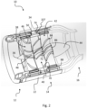
- the central rim 74 includes a hole 107 (see Fig. 2 ) within the body 80 extending from fore to aft.
- the hole 107 may be a plurality of holes arranged circumferentially. In this way, the by-pass duct 104 is able to pass air from the inlet 102 to the outlet 106.
- the outlet 104 is provided as a channel formed between the wall 22 and the exhaust nozzle 16.
- the by-pass outlet 106 is formed by the exhaust nozzle.
- the exhaust nozzle 16 includes an interior nozzle wall 109 and an exterior nozzle wall 111.
- the interior nozzle wall 109 is attached to the exterior nozzle wall 111 by means of brackets (not shown for brevity) arranged circumferentially around the nozzle.
- the exterior nozzle wall 109 is attached to the wall 22.
- the exterior nozzle wall 109 includes a recess at a fore end to receive the wall 22. Exterior surfaces of the wall 22 and the exterior nozzle wall 109 are aligned and form a continuous surface.
- the interior 109 and exterior 111 nozzle walls form the by-pass outlet 106 therebetween.
- the front motor and the rear motor are positioned within the by-pass duct 102. More specifically, the front and rear rotor irons 62, 92, the magnets 60, 90, the front and rear stator irons 64, 94, and the motor windings 66, 96, are provided within the by-pass duct 102. In this way, by-pass air is able to reduce the temperature of the front and rear motor components.
- rotational velocity of the front and rear rotors 38, 42 are independent. Velocity is taken herein to mean the angular speed and the direction. For example, the same velocity requires both speed and direction of rotation to be the same, whereas a different velocity requires at least one of the speed or the direction of rotation to be different.
- the first rotor 38 may be associated with a first direction, a first speed and a first velocity.
- the second rotor 42 may be associated with a first direction, a second speed and a second velocity.
- the first velocity may be different from the second velocity when the first and second directions differ and/or when the first and second speeds differ.
- the first velocity is the same as the second velocity when the first speed and the second speed are the same and when the first direction and the second direction are the same.
- the increase in pressure across the front rotor 38 can be controlled separately to the pressure increased across the rear rotor 42, since the rotors are independently driven.
- the front rotor 38 may be driven in an opposite direction to the rear rotor 42.
- the rotors 38, 42 may contra-rotate.
- Contra-rotating rotors 38, 42 increases the efficiency of the electrically powered fan engine 10 by increasing the pressure gain, and reducing swirl momentum in the fluid flow in the energiser chamber 14 compared to a case where the rotors 38, 42, rotate in the same direction as is the case with GB1282485 where the front and rear rotors are driven dependent on each other.
- the frusto-conical hub formed by the front hub 48, the central hub 72, and the rear hub 86 reduces a cross-sectional area of a fluid flow path through the energiser chamber 14.
- the front rim 50, the central rim 74, and the rear rim 88, in addition to the front hub 48, the central hub 72, and the rear hub 86 cooperate to reduce the flow area through the energiser chamber.
- the front rim 50, the central rim 74, and the rear rim 88, in addition to the front hub 48, the central hub 72, and the rear hub 86 cooperate to reduce the flow area through the energiser chamber 14.
- the reduction in cross-sectional area is gradual and substantially consistent along an axial length of the energiser chamber 14.
- the reduction in cross-sectional area of the annulus helps to maintain the pressure increase induced in the fluid stream by rotation of the front rotor 38 and the rear rotor 42.
- the bullet shaped exhaust fairing 44 compliments an interior convergence of the interior exhaust nozzle 109. In this way, the exhaust fairing 44 and the exhaust nozzle 16 cooperate the maintain the cross-sectional flow area substantially constant in the exhaust 16. This reduces the risk of the air decelerating.
- the guide vane 40 serves to direct the fluid flow to a leading edge of the blades 84 of the rear rotor 42 at an angle of incidence that increases the pressure gain induced by the blades 84. In this way, the blades 84 of the rear rotor 42 are less likely to operate in an aerodynamically stalled condition.
- the sealing devices help maintain the pressure increase by reducing air leakage paths between the rotors 38, 42, and the adjacent static structures.
- the bearings 54 being located within the front and rear bearing tracks 56 and 58 around the shaft 52, locates the bearing structures out of the airflow.
- a reduction in drag occurs compared to GB1282485 where the central shaft rotates as one with the rotors being fixed to it.
- the arrangement in GB1282485 requires bearing arrangements at either end of the central shaft within the airflow causing a drag increase and efficiency reduction of the electrically powered fan engine 10.
- the arrangement of the present disclosure also reduces structural effects such as vibration where the shaft can vibrate and wobble due to its inherent length and the moment applied to the shaft during rotation of the rotors as would be the case with GB1282485 .
- the device 10 may include two axially aligned rotors or may be an assembly of three or more axially aligned rotors wherein each rotor is located in front of or behind a static guide vane.
- FIGS. 1 , 2 and 3 show a fan device of the invention having a forward intake section a central energiser section and an aft exhaust nozzle section.
- the central energiser section houses a forward fan rotor and an aft fan rotor.
- the fan-rotors are able to rotate, by means of bearings which are supported on a shaft fixed to a static guide vane structure which is attached to the duct casing.
- a rim Around the periphery of each fan rotor is a rim that supports the permanent magnets and the rotor back-irons.
- the rotor magnets are arranged in a Halbach array.
- Attached to the duct casing are the laminated stator irons and the conductor windings of the motor circuits.
- the stator irons and conductor windings are configured to be slotless.
- the hub regions of the fan rotors and the guide vane structure are conical in form and tapered in order to progressively reduce the air-flow annulus-area from the nose cone, located at the ducted fan intake, to the bullet fairing located at the ducted fan outlet.
- an air-inlet aperture is located around the external peripheral surface of the ducted fan device between the intake lip and the duct casing.
- the cooling air is exhausted into the fan efflux air by means of the double-walled air channel.
- the fan rotors are caused to rotate in opposite directions (contra-rotate) by the energisation of the electrical motor circuitry acting on the rims of the fan rotors.
- the fan rotors may be provided with sealing devices to minimise air leakage paths between the rotating fans and their adjacent static structures.
Landscapes
- Engineering & Computer Science (AREA)
- Aviation & Aerospace Engineering (AREA)
- Power Engineering (AREA)
- Structures Of Non-Positive Displacement Pumps (AREA)
- Jet Pumps And Other Pumps (AREA)
Claims (15)
- Elektrisch betriebenes Mantelstromtriebwerk (10), das Folgendes beinhaltet:einen Einlass (12), eine Auslassdüse (16);einen Bypass (100), der einen Bypasseinlass (102), einen Bypasskanal (104) und einen Bypassauslass (104) umfasst;eine Energiequellenkammer (14) zwischen dem Einlass (12) und der Auslassdüse (16) des elektrisch betriebenen Mantelstromtriebwerks;einen ersten Rotor (38) innerhalb der Energiequellenkammer, wobei der erste Rotor mehrere Schaufeln (46) beinhaltet und dazu ausgelegt ist, ein Fluid von dem Einlass aufzunehmen, und dazu ausgelegt ist, sich mit einer ersten Geschwindigkeit zu drehen; undeinen zweiten Rotor (42) innerhalb der Energiequellenkammer, wobei der zweite Rotor mehrere Schaufeln (84) beinhaltet und dazu ausgelegt ist, das Fluid nach Durchlaufen des ersten Rotors aufzunehmen, und dazu ausgelegt ist, sich mit einer zweiten Geschwindigkeit zu drehen,wobei sich die erste Geschwindigkeit von der zweiten Geschwindigkeit unterscheidet,wobei der erste Rotor einen Rand (50) beinhaltet und der zweite Rotor einen Rand (88) beinhaltet,wobei das elektrisch betriebene Mantelstromtriebwerk ferner einen ersten elektromagnetischen Schaltkreis, der dazu ausgelegt ist, den Rand des ersten Rotors anzutreiben, und einen zweiten elektromagnetischen Schaltkreis, der dazu ausgelegt ist, den Rand des zweiten Rotors anzutreiben, umfasst,wobei sich der Bypasskanal (104) zwischen dem Bypasseinlass (102) und dem Bypassauslass (106) erstreckt,wobei der Bypasseinlass stromaufwärts des ersten Rotors positioniert ist, und wobei der Bypassauslass in der Auslassdüse positioniert ist, unddadurch gekennzeichnet, dass der erste elektromagnetische Schaltkreis und der zweite elektromagnetische Schaltkreis jeweils innerhalb des Bypasskanals zur Kühlung im Einsatz vorgesehen sind.
- Elektrisch betriebenes Mantelstromtriebwerk nach Anspruch 1, wobei der erste Rotor dazu ausgelegt ist, sich in einer ersten Richtung zu drehen, der zweite Rotor dazu ausgelegt ist, sich in einer zweiten Richtung zu drehen, und wobei sich die erste Richtung von der zweiten Richtung unterscheidet.
- Elektrisch betriebenes Mantelstromtriebwerk nach Anspruch 1 oder Anspruch 2, wobei der erste Rotor und der zweite Rotor unabhängig angetrieben werden, und wobei sich eine erste Drehzahl des ersten Rotors von einer zweiten Drehzahl des zweiten Rotors unterscheidet.
- Elektrisch betriebenes Mantelstromtriebwerk nach einem der vorhergehenden Ansprüche, wobei der erste Rotor und der zweite Rotor axial ausgerichtet sind.
- Elektrisch betriebenes Mantelstromtriebwerk nach einem der vorhergehenden Ansprüche, ferner umfassend eine statische Leitschaufel (40) zwischen dem ersten Rotor und dem zweiten Rotor, wobei die statische Leitschaufel mehrere Schaufeln (70) umfasst, die dazu ausgelegt sind, einen Einfallswinkel des Fluids auf die Schaufeln des zweiten Rotors zu steuern.
- Elektrisch betriebenes Mantelstromtriebwerk nach Anspruch 5, wobei der erste Rotor, die statische Leitschaufel und der zweite Rotor jeweils eine Nabe (48, 72, 86) beinhalten, von der sich die jeweiligen Schaufeln radial erstrecken.
- Elektrisch betriebenes Mantelstromtriebwerk nach Anspruch 6, wobei die Naben jeweils des ersten Rotors, der statischen Leitschaufel und des zweiten Rotors mit einer Innenfläche der Energiequellenkammer zusammenwirken, um eine Querschnittsfläche der Energiequellenkammer vom Einlass zum Auslass allmählich zu verringern.
- Elektrisch betriebenes Mantelstromtriebwerk nach Anspruch 7, wobei sich die Naben jeweils des ersten Rotors, der statischen Leitschaufel und des zweiten Rotors verbinden, um eine im Wesentlichen kegelstumpfförmige Oberfläche mit einem Durchmesser zu bilden, der allmählich vom Einlass zu einem Auslass zunimmt.
- Elektrisch betriebenes Mantelstromtriebwerk nach einem der Ansprüche 6 bis 8, wobei die Nabe der statischen Leitschaufel einen vorderen Achsstummel und einen hinteren Achsstummel beinhaltet, die sich jeweils davon nach vorne und hinten erstrecken, und wobei die Nabe des ersten Rotors und die Nabe des zweiten Rotors um den jeweiligen vorderen und hinteren Achsstummel gelagert sind.
- Elektrisch betriebenes Mantelstromtriebwerk nach einem der vorhergehenden Ansprüche, ferner umfassend eine Auslassdüse (16) am Auslass und eine Auslassverkleidung, die sich von der Nabe des zweiten Rotors erstreckt, wobei die Auslassdüse und die Auslassverkleidung zusammenwirken, um eine Querschnittsfläche des Auslasses von der Energiequellenkammer Richtung stromabwärts beizubehalten.
- Elektrisch betriebenes Mantelstromtriebwerk nach Anspruch 10, wobei die Auslassdüse konvergent ist und die Auslassverkleidung im Wesentlichen kugelförmig ist.
- Elektrisch betriebenes Mantelstromtriebwerk nach Anspruch 1, wobei der erste elektromagnetische Schaltkreis mehrere Wicklungen (66) und ein Statoreisen (64), das an einer Wand (22) montiert ist, die die Energiequellenkammer umgibt, und ein Rotoreisen (62) und mehrere Magnete, die am Rand des ersten Rotors montiert sind, beinhaltet, und wobei der zweite elektromagnetische Schaltkreis mehrere Wicklungen (96) und ein Statoreisen (94), das an der Wand montiert ist, die die Energiequellenkammer umgibt, und ein Rotoreisen (92) und mehrere Wicklungen (96), die am Rand des zweiten Rotors montiert sind, beinhaltet.
- Elektrisch betriebenes Mantelstromtriebwerk nach Anspruch 1, wobei die statische Leitschaufel einen Rand (74) beinhaltet, der mit einer Innenfläche der Wand gekoppelt ist, wobei der Rand einen Fluiddurchlass beinhaltet, um zu ermöglichen, dass Fluid von dem Bypasseinlass zu dem Bypassauslass strömt.
- Elektrisch betriebenes Mantelstromtriebwerk nach Anspruch 5 oder einem davon abhängigen Anspruch, ferner umfassend eine Pylonbefestigung (18), wobei die statische Leitschaufel mit der Pylonbefestigung gekoppelt ist, um eine Schubkraft darauf zu übertragen.
- Elektrisch betriebenes Mantelstromtriebwerk nach einem der vorhergehenden Ansprüche, wobei das elektrisch betriebene Mantelstromtriebwerk zum Bereitstellen von Schub und/oder Auftrieb zu einem Luftfahrzeug dient.
Applications Claiming Priority (3)
| Application Number | Priority Date | Filing Date | Title |
|---|---|---|---|
| GBGB2018240.8A GB202018240D0 (en) | 2020-11-19 | 2020-11-19 | Rim driven fan device |
| GB2107186.5A GB2601209B (en) | 2020-11-19 | 2021-05-19 | Electrically powered fan engine |
| PCT/EP2021/082382 WO2022106664A1 (en) | 2020-11-19 | 2021-11-19 | Electrically powered engine |
Publications (2)
| Publication Number | Publication Date |
|---|---|
| EP4247708A1 EP4247708A1 (de) | 2023-09-27 |
| EP4247708B1 true EP4247708B1 (de) | 2025-04-23 |
Family
ID=74046849
Family Applications (1)
| Application Number | Title | Priority Date | Filing Date |
|---|---|---|---|
| EP21816024.0A Active EP4247708B1 (de) | 2020-11-19 | 2021-11-19 | Elektrisch angetriebener motor |
Country Status (5)
| Country | Link |
|---|---|
| US (1) | US12237751B2 (de) |
| EP (1) | EP4247708B1 (de) |
| CA (1) | CA3201454A1 (de) |
| GB (2) | GB202018240D0 (de) |
| WO (1) | WO2022106664A1 (de) |
Families Citing this family (3)
| Publication number | Priority date | Publication date | Assignee | Title |
|---|---|---|---|---|
| WO2018175349A1 (en) * | 2017-03-19 | 2018-09-27 | Zunum Aero, Inc. | Hybrid-electric aircraft, and methods, apparatus and systems for facilitating same |
| GB2613541A (en) * | 2021-11-30 | 2023-06-14 | Airbus Sas | Shielding arrangement for aircraft wiring |
| CN114313219B (zh) * | 2022-02-18 | 2023-03-24 | 南京航空航天大学 | 一种新型对转风扇推进结构 |
Family Cites Families (8)
| Publication number | Priority date | Publication date | Assignee | Title |
|---|---|---|---|---|
| GB1282485A (en) | 1968-07-25 | 1972-07-19 | Ludwig F Meditz | Electric motor driven ducted fan assembly |
| DE102006023681B4 (de) | 2006-05-19 | 2009-07-02 | Knorr-Bremse Systeme für Nutzfahrzeuge GmbH | Verfahren zum Steuern beziehungsweise Regeln des Luftdrucks in einer Druckluftversorgungseinrichtung |
| US9143023B1 (en) * | 2010-05-17 | 2015-09-22 | Richard Christopher Uskert | Electromagnetic propulsive motor |
| RU2017131217A (ru) * | 2015-02-06 | 2019-03-06 | Флорида Турбин Текнолоджиз, Инк. | Устройство и способ переоснащения силовой установки комбинированного цикла |
| US11649049B2 (en) * | 2018-06-28 | 2023-05-16 | Justin Wesley Green | Unmanned coaxial rotor aerial vehicle for transport of heavy loads |
| GB201814869D0 (en) * | 2018-09-03 | 2018-10-31 | Rolls Royce Plc | Aircraft Propulsion System |
| GB201900478D0 (en) * | 2019-01-14 | 2019-02-27 | Rolls Royce Plc | Turbomachine |
| US11739694B2 (en) * | 2020-04-15 | 2023-08-29 | General Electric Company | Embedded electric motor assembly |
-
2020
- 2020-11-19 GB GBGB2018240.8A patent/GB202018240D0/en not_active Ceased
-
2021
- 2021-05-19 GB GB2107186.5A patent/GB2601209B/en active Active
- 2021-11-19 US US18/036,689 patent/US12237751B2/en active Active
- 2021-11-19 EP EP21816024.0A patent/EP4247708B1/de active Active
- 2021-11-19 WO PCT/EP2021/082382 patent/WO2022106664A1/en not_active Ceased
- 2021-11-19 CA CA3201454A patent/CA3201454A1/en active Pending
Also Published As
| Publication number | Publication date |
|---|---|
| GB202018240D0 (en) | 2021-01-06 |
| US12237751B2 (en) | 2025-02-25 |
| WO2022106664A1 (en) | 2022-05-27 |
| CA3201454A1 (en) | 2022-05-27 |
| EP4247708A1 (de) | 2023-09-27 |
| US20230415903A1 (en) | 2023-12-28 |
| GB202107186D0 (en) | 2021-06-30 |
| GB2601209B (en) | 2023-01-18 |
| GB2601209A (en) | 2022-05-25 |
Similar Documents
| Publication | Publication Date | Title |
|---|---|---|
| EP3626611B1 (de) | Flugzeugantriebssystem | |
| US11059599B2 (en) | Electric aircraft propulsion system | |
| US12237751B2 (en) | Electrically powered engine | |
| GB2565886B (en) | Electric engine | |
| CN109071030B (zh) | 用于飞行器的推进发动机 | |
| US12246842B2 (en) | Motor-integrated fluid machine and vertical take-off and landing aircraft | |
| WO2007001372A2 (en) | Ducted spinner for engine cooling | |
| CN108488082B (zh) | 飞行器用电驱扭矩自平衡无轴涵道风扇或无轴涵道桨叶 | |
| WO2020122056A1 (ja) | モータ一体型ファン及び垂直離着陸機 | |
| JP7358280B2 (ja) | ダクテッドファン及び航空機 | |
| US11952133B2 (en) | Motor-integrated fluid machine and vertical takeoff and landing aircraft | |
| CN216887200U (zh) | 一种单涵道飞行器 | |
| CN113978740B (zh) | 航空用的双转子轮缘驱动型内外涵道式推进器 | |
| US12395023B2 (en) | Rotor for an electric aircraft motor and a method for manufacturing | |
| WO2020158361A1 (ja) | モータ一体型流体機械及び垂直離着陸機 | |
| CN114476048B (zh) | 一种基于轮缘驱动技术的翼缘融合推进结构 | |
| JP2022129157A (ja) | 流体機械および垂直離着陸機 | |
| US12107459B2 (en) | Rotor for an electric aircraft motor comprising a plurality of magnets | |
| EP4163497A1 (de) | Mehrstufiger axialkompressorantriebsmotor für ein flugzeug mit elektroantrieb | |
| WO2023286785A1 (ja) | 電動ファンおよび電動垂直離着陸機 | |
| CN114789787A (zh) | 一种单涵道飞行器 | |
| KR20230059377A (ko) | 비행용 전기추진장치 |
Legal Events
| Date | Code | Title | Description |
|---|---|---|---|
| STAA | Information on the status of an ep patent application or granted ep patent |
Free format text: STATUS: UNKNOWN |
|
| STAA | Information on the status of an ep patent application or granted ep patent |
Free format text: STATUS: THE INTERNATIONAL PUBLICATION HAS BEEN MADE |
|
| PUAI | Public reference made under article 153(3) epc to a published international application that has entered the european phase |
Free format text: ORIGINAL CODE: 0009012 |
|
| STAA | Information on the status of an ep patent application or granted ep patent |
Free format text: STATUS: REQUEST FOR EXAMINATION WAS MADE |
|
| 17P | Request for examination filed |
Effective date: 20230530 |
|
| AK | Designated contracting states |
Kind code of ref document: A1 Designated state(s): AL AT BE BG CH CY CZ DE DK EE ES FI FR GB GR HR HU IE IS IT LI LT LU LV MC MK MT NL NO PL PT RO RS SE SI SK SM TR |
|
| DAV | Request for validation of the european patent (deleted) | ||
| DAX | Request for extension of the european patent (deleted) | ||
| GRAP | Despatch of communication of intention to grant a patent |
Free format text: ORIGINAL CODE: EPIDOSNIGR1 |
|
| STAA | Information on the status of an ep patent application or granted ep patent |
Free format text: STATUS: GRANT OF PATENT IS INTENDED |
|
| INTG | Intention to grant announced |
Effective date: 20241114 |
|
| GRAS | Grant fee paid |
Free format text: ORIGINAL CODE: EPIDOSNIGR3 |
|
| GRAA | (expected) grant |
Free format text: ORIGINAL CODE: 0009210 |
|
| STAA | Information on the status of an ep patent application or granted ep patent |
Free format text: STATUS: THE PATENT HAS BEEN GRANTED |
|
| RAP3 | Party data changed (applicant data changed or rights of an application transferred) |
Owner name: BOLAM, ROBERT CAMERON |
|
| RIN1 | Information on inventor provided before grant (corrected) |
Inventor name: BOLAM, ROBERT CAMERON |
|
| AK | Designated contracting states |
Kind code of ref document: B1 Designated state(s): AL AT BE BG CH CY CZ DE DK EE ES FI FR GB GR HR HU IE IS IT LI LT LU LV MC MK MT NL NO PL PT RO RS SE SI SK SM TR |
|
| REG | Reference to a national code |
Ref country code: GB Ref legal event code: FG4D |
|
| REG | Reference to a national code |
Ref country code: CH Ref legal event code: EP |
|
| REG | Reference to a national code |
Ref country code: DE Ref legal event code: R096 Ref document number: 602021029717 Country of ref document: DE |
|
| REG | Reference to a national code |
Ref country code: IE Ref legal event code: FG4D |
|
| P01 | Opt-out of the competence of the unified patent court (upc) registered |
Free format text: CASE NUMBER: APP_30750/2025 Effective date: 20250626 |
|
| REG | Reference to a national code |
Ref country code: NL Ref legal event code: MP Effective date: 20250423 |
|
| PG25 | Lapsed in a contracting state [announced via postgrant information from national office to epo] |
Ref country code: NL Free format text: LAPSE BECAUSE OF FAILURE TO SUBMIT A TRANSLATION OF THE DESCRIPTION OR TO PAY THE FEE WITHIN THE PRESCRIBED TIME-LIMIT Effective date: 20250423 |
|
| REG | Reference to a national code |
Ref country code: AT Ref legal event code: MK05 Ref document number: 1787564 Country of ref document: AT Kind code of ref document: T Effective date: 20250423 |
|
| PG25 | Lapsed in a contracting state [announced via postgrant information from national office to epo] |
Ref country code: FI Free format text: LAPSE BECAUSE OF FAILURE TO SUBMIT A TRANSLATION OF THE DESCRIPTION OR TO PAY THE FEE WITHIN THE PRESCRIBED TIME-LIMIT Effective date: 20250423 Ref country code: PT Free format text: LAPSE BECAUSE OF FAILURE TO SUBMIT A TRANSLATION OF THE DESCRIPTION OR TO PAY THE FEE WITHIN THE PRESCRIBED TIME-LIMIT Effective date: 20250825 Ref country code: ES Free format text: LAPSE BECAUSE OF FAILURE TO SUBMIT A TRANSLATION OF THE DESCRIPTION OR TO PAY THE FEE WITHIN THE PRESCRIBED TIME-LIMIT Effective date: 20250423 |
|
| REG | Reference to a national code |
Ref country code: LT Ref legal event code: MG9D |
|
| PG25 | Lapsed in a contracting state [announced via postgrant information from national office to epo] |
Ref country code: NO Free format text: LAPSE BECAUSE OF FAILURE TO SUBMIT A TRANSLATION OF THE DESCRIPTION OR TO PAY THE FEE WITHIN THE PRESCRIBED TIME-LIMIT Effective date: 20250723 Ref country code: GR Free format text: LAPSE BECAUSE OF FAILURE TO SUBMIT A TRANSLATION OF THE DESCRIPTION OR TO PAY THE FEE WITHIN THE PRESCRIBED TIME-LIMIT Effective date: 20250724 |
|
| PG25 | Lapsed in a contracting state [announced via postgrant information from national office to epo] |
Ref country code: PL Free format text: LAPSE BECAUSE OF FAILURE TO SUBMIT A TRANSLATION OF THE DESCRIPTION OR TO PAY THE FEE WITHIN THE PRESCRIBED TIME-LIMIT Effective date: 20250423 |
|
| PG25 | Lapsed in a contracting state [announced via postgrant information from national office to epo] |
Ref country code: BG Free format text: LAPSE BECAUSE OF FAILURE TO SUBMIT A TRANSLATION OF THE DESCRIPTION OR TO PAY THE FEE WITHIN THE PRESCRIBED TIME-LIMIT Effective date: 20250423 |
|
| PG25 | Lapsed in a contracting state [announced via postgrant information from national office to epo] |
Ref country code: HR Free format text: LAPSE BECAUSE OF FAILURE TO SUBMIT A TRANSLATION OF THE DESCRIPTION OR TO PAY THE FEE WITHIN THE PRESCRIBED TIME-LIMIT Effective date: 20250423 |
|
| PG25 | Lapsed in a contracting state [announced via postgrant information from national office to epo] |
Ref country code: AT Free format text: LAPSE BECAUSE OF FAILURE TO SUBMIT A TRANSLATION OF THE DESCRIPTION OR TO PAY THE FEE WITHIN THE PRESCRIBED TIME-LIMIT Effective date: 20250423 |
|
| PG25 | Lapsed in a contracting state [announced via postgrant information from national office to epo] |
Ref country code: RS Free format text: LAPSE BECAUSE OF FAILURE TO SUBMIT A TRANSLATION OF THE DESCRIPTION OR TO PAY THE FEE WITHIN THE PRESCRIBED TIME-LIMIT Effective date: 20250723 |
|
| PG25 | Lapsed in a contracting state [announced via postgrant information from national office to epo] |
Ref country code: IS Free format text: LAPSE BECAUSE OF FAILURE TO SUBMIT A TRANSLATION OF THE DESCRIPTION OR TO PAY THE FEE WITHIN THE PRESCRIBED TIME-LIMIT Effective date: 20250823 |
|
| PG25 | Lapsed in a contracting state [announced via postgrant information from national office to epo] |
Ref country code: LV Free format text: LAPSE BECAUSE OF FAILURE TO SUBMIT A TRANSLATION OF THE DESCRIPTION OR TO PAY THE FEE WITHIN THE PRESCRIBED TIME-LIMIT Effective date: 20250423 |
|
| PGFP | Annual fee paid to national office [announced via postgrant information from national office to epo] |
Ref country code: DE Payment date: 20251119 Year of fee payment: 5 |
|
| PG25 | Lapsed in a contracting state [announced via postgrant information from national office to epo] |
Ref country code: SM Free format text: LAPSE BECAUSE OF FAILURE TO SUBMIT A TRANSLATION OF THE DESCRIPTION OR TO PAY THE FEE WITHIN THE PRESCRIBED TIME-LIMIT Effective date: 20250423 Ref country code: DK Free format text: LAPSE BECAUSE OF FAILURE TO SUBMIT A TRANSLATION OF THE DESCRIPTION OR TO PAY THE FEE WITHIN THE PRESCRIBED TIME-LIMIT Effective date: 20250423 |
|
| PGFP | Annual fee paid to national office [announced via postgrant information from national office to epo] |
Ref country code: FR Payment date: 20251126 Year of fee payment: 5 |
|
| PG25 | Lapsed in a contracting state [announced via postgrant information from national office to epo] |
Ref country code: CZ Free format text: LAPSE BECAUSE OF FAILURE TO SUBMIT A TRANSLATION OF THE DESCRIPTION OR TO PAY THE FEE WITHIN THE PRESCRIBED TIME-LIMIT Effective date: 20250423 |
|
| PG25 | Lapsed in a contracting state [announced via postgrant information from national office to epo] |
Ref country code: EE Free format text: LAPSE BECAUSE OF FAILURE TO SUBMIT A TRANSLATION OF THE DESCRIPTION OR TO PAY THE FEE WITHIN THE PRESCRIBED TIME-LIMIT Effective date: 20250423 |
|
| REG | Reference to a national code |
Ref country code: DE Ref legal event code: R097 Ref document number: 602021029717 Country of ref document: DE |
|
| PG25 | Lapsed in a contracting state [announced via postgrant information from national office to epo] |
Ref country code: SK Free format text: LAPSE BECAUSE OF FAILURE TO SUBMIT A TRANSLATION OF THE DESCRIPTION OR TO PAY THE FEE WITHIN THE PRESCRIBED TIME-LIMIT Effective date: 20250423 |
|
| PG25 | Lapsed in a contracting state [announced via postgrant information from national office to epo] |
Ref country code: IT Free format text: LAPSE BECAUSE OF FAILURE TO SUBMIT A TRANSLATION OF THE DESCRIPTION OR TO PAY THE FEE WITHIN THE PRESCRIBED TIME-LIMIT Effective date: 20250423 |
|
| PLBE | No opposition filed within time limit |
Free format text: ORIGINAL CODE: 0009261 |
|
| STAA | Information on the status of an ep patent application or granted ep patent |
Free format text: STATUS: NO OPPOSITION FILED WITHIN TIME LIMIT |
|
| REG | Reference to a national code |
Ref country code: CH Ref legal event code: L10 Free format text: ST27 STATUS EVENT CODE: U-0-0-L10-L00 (AS PROVIDED BY THE NATIONAL OFFICE) Effective date: 20260304 |
|
| PG25 | Lapsed in a contracting state [announced via postgrant information from national office to epo] |
Ref country code: RO Free format text: LAPSE BECAUSE OF FAILURE TO SUBMIT A TRANSLATION OF THE DESCRIPTION OR TO PAY THE FEE WITHIN THE PRESCRIBED TIME-LIMIT Effective date: 20250423 |
|
| 26N | No opposition filed |
Effective date: 20260126 |
|
| PGFP | Annual fee paid to national office [announced via postgrant information from national office to epo] |
Ref country code: GB Payment date: 20260123 Year of fee payment: 5 |