EP4247296B1 - Saugvorrichtung - Google Patents
Saugvorrichtung Download PDFInfo
- Publication number
- EP4247296B1 EP4247296B1 EP21823365.8A EP21823365A EP4247296B1 EP 4247296 B1 EP4247296 B1 EP 4247296B1 EP 21823365 A EP21823365 A EP 21823365A EP 4247296 B1 EP4247296 B1 EP 4247296B1
- Authority
- EP
- European Patent Office
- Prior art keywords
- suction device
- suction
- shell
- external shell
- openings
- Prior art date
- Legal status (The legal status is an assumption and is not a legal conclusion. Google has not performed a legal analysis and makes no representation as to the accuracy of the status listed.)
- Active
Links
Images


Classifications
-
- A—HUMAN NECESSITIES
- A61—MEDICAL OR VETERINARY SCIENCE; HYGIENE
- A61C—DENTISTRY; APPARATUS OR METHODS FOR ORAL OR DENTAL HYGIENE
- A61C17/00—Devices for cleaning, polishing, rinsing or drying teeth, teeth cavities or prostheses; Saliva removers; Dental appliances for receiving spittle
- A61C17/06—Saliva removers; Accessories therefor
- A61C17/08—Aspiration nozzles
-
- A—HUMAN NECESSITIES
- A61—MEDICAL OR VETERINARY SCIENCE; HYGIENE
- A61C—DENTISTRY; APPARATUS OR METHODS FOR ORAL OR DENTAL HYGIENE
- A61C17/00—Devices for cleaning, polishing, rinsing or drying teeth, teeth cavities or prostheses; Saliva removers; Dental appliances for receiving spittle
- A61C17/14—Dental appliances for receiving spittle, with or without rinsing means therefor, e.g. dental basins, spittoons, cuspidors
Definitions
- the present invention relates to a suction device configured to suck a fluid or an aerosol going out from a patient's mouth during a dental procedure.
- suction devices capable of sucking the fluids present in the working area or the aerosol outgoing from a patient's mouth.
- a suction device for dental use of known type comprises a cannula, configured to be inserted, upon need, in a patient's mouth, to allow the localized suction of fluids such as water, saliva, blood, and so on.
- the cannula is configured to be connected to a suction source and along its tract it has a shield configured to intercept possible particles, biological material or solid debris thrown outside a patient's mouth and to convey them towards the suction openings delimited along the cannula itself.
- Such device has a limited capability of intercepting the aerosol cloud outgoing from a patient's mouth. Consequently, even the capability of guaranteeing an operator safety in proximity of the working area results to be limited and so as not to reduce drastically the risk of professional exposure.
- US4865545A discloses a fluid and debris-removing aspirator for use by dentists, comprising a cup-shaped double-wall receptacle providing a container to receive excess drips.
- An additional suction device of known type comprises the use of a fixed shield connected through a suction orifice to a suction source.
- the fixed shield is installed at the chair whereon a patient is positioned, distant from the patient's mouth.
- the object of the present invention is to allow in a simple, ergonomic, effective and unexpensive way to suck the aerosol produced during a dental procedure to avoid the biological and chemical risks connected thereto, thus by optimizing the working conditions.
- An additional object of the present invention is to provide a suction device capable of guaranteeing an effective suction action, so as to allow to intercept wholly the aerosol cloud emitted by a patient's mouth, as from the immediate proximity of the mouth itself.
- Another object of the present invention is to provide a suction device which is easy to be implemented and lasting.
- Another object of the present invention is to provide a suction device which is of practical use and configured to keep the working area free and accessible.
- An additional object of the present invention is to provide a suction device configured to be connected to a suction device already available in a dental environment, for example with reference to a suction device with which a dental chair is equipped, then within an extremely flexible use solution and which does not require any additional machinery with respect to those available for its use.
- the invention specifically relates to a suction device configured as a concave body comprising opposite lateral portions which define a bottom edge and a front edge, wherein the bottom edge and the front edge delimit the access to an inner cavity of the suction device, the suction device comprising an external shell and an internal shell mutually coupled in a spaced position so as to delimit between them an interspace, a suction port which extends externally to the suction device starting from the external shell, the suction port being configured to be connected to a suction source and being in fluid communication with the interspace, the internal shell delimiting a plurality of through-openings which are in fluid communication with the suction port through the interspace, wherein the suction device is configured to be positioned at a patient's chin or nose.
- the openings of the plurality of through-openings can have the same size or different sizes depending upon their positioning along the internal shell.
- the suction port delimits at least one opening passing through the external shell.
- the suction port can be sealingly connected to the external shell.
- the external shell and the internal shell can be mutually sealed at the bottom edge and the front edge.
- the external shell and the internal shell can be made of plastic or resin.
- the suction device can include at least one spacer element interposed between the external shell and the internal shell.
- the bottom edge and the front edge can lie respectively on a bottom surface and a front surface, wherein the bottom surface and the front surface intersect each other.
- At least one of the bottom surface and the front surface can be at least partially flat.
- the suction device according to the invention is configured to be positioned at a patient's mouth while carrying out a dental procedure, in the immediate proximity of the mouth, and to guarantee an effective suction action.
- the suction device allows to capture the aerosol cloud generated during the procedure, by intercepting it immediately when it outgoes from the patient's mouth, thus preventing the spread of biological and chemical contaminants contained therein.
- the suction device guarantees an effective suction of the aerosol which is produced, by allowing to perform a procedure in complete safety not only for the operators but even for the patient himself/herself.
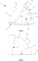
- FIG. 1 a preferred embodiment of a suction device according to the invention, designated as a whole with 1, can be observed.
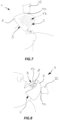
- the suction device 1 is configured like a mask or substantially like a mask which can be positioned at a patient's mandible or nose (see Figure 7 ) or jaw or chin (see Figure 8 ).
- the same suction device 1 can be positioned in two different portions of a patient's face, by resulting extremely flexible in its use.
- the suction device 1 is configured as truncated concave body or truncated cup delimiting an inner cavity.
- the suction device 1 has opposite lateral portions which define a bottom edge 2 and a front edge 3 (see for example Figures 1 and 2 ).
- the bottom edge 2 and the front edge 3 lie respectively on a bottom surface 4 and on a front surface 5.
- the bottom surface 4 and the front surface 5 are illustrated flat while meaning that one or both of them can be configured curved depending upon the shape one wishes to confer to the suction device 1 and, in particular, to the bottom edge 2 and the front edge 3.
- At least one of the bottom surface 4 and the front surface 5 is at least partially flat.
- the bottom surface 4 and the front surface 5 intersect each other and delimit an angle 6.
- the angle 6 has a value equal to 90° or substantially equal to 90°, higher or lower than 90°, but anyway around 90°.
- angle 6 is comprised between 90° and 150° or between 45° and 90°, depending upon specific use needs, to allow the implementation of a suction device 1 suitable to the anatomic measures of several patients.
- the bottom edge 2 and the front edge 3 are configured like an arc, vault or the like.
- the bottom edge 2 and the front edge 3 delimit the access to the inner cavity of the suction device 1 or a resting counterpart.
- the bottom edge 2 and the front edge 3 can be shaped so as to be compatible with the shape of a patient's mandible or jaw portion, respectively, to allow as said the positioning of the suction device 1 respectively at the chin or nose.
- the suction device 1 comprises an external shell 7 and an internal shell 8 mutually coupled in a spaced position therebetween.
- the external shell 7 and the internal shell 8 are overlapped to each other, mutually spaced apart.
- the external shell 7 and the internal shell 8 delimit an interspace 9 therebetween.
- the external shell 7 and the internal shell 8 are mutually sealingly connected at least at the bottom edge 2 and the front edge 3 (see Figure 1 ).
- the suction device 1 comprises a suction port 10 which extends externally to the suction device 1 starting from the external shell 7.
- connection between the suction port 10 and the external shell 7 is sealed, meaning that it has no leakages at the interface existing between them.
- the suction port 10 delimits at least an opening 11 which develops passing through the external shell 7. Therefore, the suction port 10 is in fluid communication with the inside of the interspace 9.
- the suction port 10 is configured to be operatively connected to a source for the vacuum, not illustrated in the enclosed Figures.
- the suction port 10 extends from the external shell 7 along a direction orthogonal to the external shell 7 or tilted direction, without any limitation, depending upon the use needs.
- suction port 10 is configured to be sealingly connected to a connector 12 of standard type in turn connected to an aspirator according to the modes within the comprehension of a person skilled in the art, which will not be described in details.
- the suction port 10 can be connected to a suction tube of a suction unit existing in a dental chair, without requiring the use of additional machinery.
- the internal shell 8 has a plurality of through-openings 13.
- the plurality of through-openings 13 is implemented along the internal shell 8 except an inner portion 14 facing at least on the opening 11 of the suction port 10.
- the inner portion 14 extends on a surface at least equal or larger than that delimited by the at least one opening 11.
- the inner portion 14 allows to distribute the suction action through the plurality of through-openings.
- the plurality of through-openings 13 comprises through-openings 13 having the same or different sizes depending upon their positioning along the internal shell 8, with the purpose of optimizing the suction action through the inner cavity of the suction device 1.
- the plurality of through-openings 13 is in fluid communication with the interspace 9.
- the interspace 9 is in fluid communication with the outside of the suction device 1 on one side through the suction port 10 and on the other side through the plurality of through-openings 13. It means that the plurality of through-openings 13 is in fluid communication with the suction port 10 through the interspace 9.
- the arrangement of the plurality of through-openings 13 allows to distribute effectively the suction action through the internal shell 8.
- the external shell 7 and the internal shell 8 can be made of plastic or resin or, more generally, a material usually used by dentists to implement dental devices such as braces, bites or the like, thus limiting the production costs of the suction device 1.
- the suction device 1 can be implemented in different sizes, for example standardized in small, average or big size, so as to reduce the production costs of the same.
- the suction device 1 can be equally custom-made, based upon a patient's conformation, to better adapt to the anatomy of the latter.
- the enclosed Figures 1 to 4 show a suction device 1 which has an angular shape at a top portion thereof, whereas the enclosed Figures 5 to 8 show a more rounded suction device 1, while meaning that both embodiments are capable of pursuing the same object.
- the suction device 1 comprises at least one spacer element 15 interposed between the external shell 7 and the internal shell 8 (see Figure 1 ).
- the at least one spacer element 15 is comprised inside the interspace 9 and it acts as stiffening element, configured to keep the external shell 7 and the internal shell 8 spaced thereapart and to avoid to squeeze the internal shell 8 against the external shell 7, for example under the suction action.
- Such squeezing in fact, reduces the free section of the interspace 9, by compromising the air passage and, thus, by limiting the suction action through the internal shell 8.
- At least the internal shell 8 can has a reduced thickness to the advantage of a greater lightness of the suction device 1.
- the at least one spacer element 15 is configured to limit the pressure losses inside the interspace 9.
- the at least one spacer element 15 is configured cylindrical.
- the overall dimension of the suction device 1 is limited and therefore it does not obstacle the motion freedom of an operator during a dental procedure.
- the suction device 1 is configured to be able to be positioned at the chin and, then, below with respect to a patient's mouth or at the nose and, then, above with respect to the patient's mouth, thus providing a wide use flexibility.
Landscapes
- Health & Medical Sciences (AREA)
- Dentistry (AREA)
- Epidemiology (AREA)
- Life Sciences & Earth Sciences (AREA)
- Animal Behavior & Ethology (AREA)
- General Health & Medical Sciences (AREA)
- Public Health (AREA)
- Veterinary Medicine (AREA)
- Oral & Maxillofacial Surgery (AREA)
- Dental Tools And Instruments Or Auxiliary Dental Instruments (AREA)
Claims (8)
- Saugvorrichtung (1), die als konkaver Körper konfiguriert ist, umfassend gegenüberliegende seitliche Abschnitte, die eine unteren Rand (2) und einen vorderen Rand (3) definieren, wobei der untere Rand (2) und der vordere Rand (3) den Zugang zu einem inneren Hohlraum der Saugvorrichtung (1) begrenzen, wobei die Saugvorrichtung (1) eine Außenschale (7) und eine Innenschale (8) umfasst, die in einer beabstandeten Position miteinander verbunden sind, um zwischen ihnen einen Zwischenraum (9) abzugrenzen, wobei sich ein Sauganschluss (10) ausgehend von der Außenschale (7) außerhalb der Saugvorrichtung (1) erstreckt, wobei der Sauganschluss (10) so konfiguriert ist, dass er an eine Saugquelle angeschlossen werden kann und in Fluidverbindung mit dem Zwischenraum (9) steht, wobei die Innenschale (8) eine Vielzahl von Durchgangsöffnungen (13) begrenzt, die durch den Zwischenraum (9) in Fluidverbindung mit dem Sauganschluss (10) stehen, wobei die Saugvorrichtung (1) so konfiguriert ist, dass sie am Kinn oder an der Nase eines Patienten positioniert werden kann,wobei der Sauganschluss (10) mindestens eine Öffnung (11) begrenzt, die durch die Außenschale (7) verläuft,und wobei die Innenschale (8) einen Innenabschnitt (14) ohne Durchgangsöffnungen (13) aufweist, wobei der Innenabschnitt (14) mindestens der mindestens einen Öffnung (11) zugewandt ist.
- Saugvorrichtung (1) nach Anspruch 1, wobei die Öffnungen der Vielzahl von Durchgangsöffnungen (13) je nach ihrer Positionierung entlang der Innenschale (8) gleiche oder unterschiedliche Größen aufweisen.
- Saugvorrichtung (1) nach einem der vorstehenden Ansprüche, wobei die Saugöffnung (10) abdichtend mit der Außenhülle (7) verbunden ist.
- Saugvorrichtung (1) nach Anspruch 1, wobei die Außenschale (7) und die Innenschale (8) am unteren Rand (2) und dem vorderen Rand (3) gegenseitig abgedichtet sind.
- Saugvorrichtung (1) nach einem der vorstehenden Ansprüche, wobei die Außenschale (7) und die Innenschale (8) aus Kunststoff oder Harz hergestellt sind.
- Saugvorrichtung (1) nach einem der vorstehenden Ansprüche, die mindestens ein Abstandselement (15) umfasst, das zwischen der Außenschale (7) und der Innenschale (8) angeordnet ist.
- Saugvorrichtung (1) nach einem der vorstehenden Ansprüche, wobei der untere Rand (2) und der vordere Rand (3) jeweils auf einer unteren Oberfläche (4) und einer vorderen Oberfläche (5) liegen, wobei die untere Oberfläche (4) und die vordere Oberfläche (5) einander überschneiden.
- Saugvorrichtung (1) nach Anspruch 7, wobei mindestens eine der unteren Oberfläche (4) und der vorderen Oberfläche (5) mindestens teilweise flach ist.
Applications Claiming Priority (2)
| Application Number | Priority Date | Filing Date | Title |
|---|---|---|---|
| IT202000027789 | 2020-11-19 | ||
| PCT/IB2021/060609 WO2022106995A1 (en) | 2020-11-19 | 2021-11-16 | Suction device |
Publications (3)
| Publication Number | Publication Date |
|---|---|
| EP4247296A1 EP4247296A1 (de) | 2023-09-27 |
| EP4247296C0 EP4247296C0 (de) | 2024-09-18 |
| EP4247296B1 true EP4247296B1 (de) | 2024-09-18 |
Family
ID=74592424
Family Applications (1)
| Application Number | Title | Priority Date | Filing Date |
|---|---|---|---|
| EP21823365.8A Active EP4247296B1 (de) | 2020-11-19 | 2021-11-16 | Saugvorrichtung |
Country Status (2)
| Country | Link |
|---|---|
| EP (1) | EP4247296B1 (de) |
| WO (1) | WO2022106995A1 (de) |
Family Cites Families (3)
| Publication number | Priority date | Publication date | Assignee | Title |
|---|---|---|---|---|
| US4865545A (en) * | 1988-07-27 | 1989-09-12 | Rocca Nina | Dental aspirator |
| DE102005016531A1 (de) * | 2005-04-08 | 2006-10-12 | Georg Schick Dental Gmbh | Absaugwanne für Werkstoffbearbeitungsmaschinen, insbesondere für Dentalfräsgeräte |
| US9358086B2 (en) * | 2014-05-22 | 2016-06-07 | Innerlite, Inc. | Intraoral device and method of use |
-
2021
- 2021-11-16 WO PCT/IB2021/060609 patent/WO2022106995A1/en not_active Ceased
- 2021-11-16 EP EP21823365.8A patent/EP4247296B1/de active Active
Also Published As
| Publication number | Publication date |
|---|---|
| EP4247296C0 (de) | 2024-09-18 |
| WO2022106995A1 (en) | 2022-05-27 |
| EP4247296A1 (de) | 2023-09-27 |
Similar Documents
| Publication | Publication Date | Title |
|---|---|---|
| US3781994A (en) | Arrangement for separating an area of operation or treatment in the oral cavity | |
| US5224940A (en) | Device and method for protecting health personnel from body fluid backsplash | |
| US12383388B2 (en) | Dental aerosol protection system | |
| CN210494258U (zh) | 一种用于口腔手术操作的防护隔离罩 | |
| US20210338377A1 (en) | Dental dam frame and methods of use thereof | |
| US20210353395A1 (en) | Suction system | |
| US20210346134A1 (en) | Lip retractor and suction head for high-volume evacuator | |
| US3735491A (en) | Dental shielding device | |
| US4976254A (en) | Endoscopy shield | |
| EP4153089A2 (de) | Flexible gesichtsmaske für verschiedene dentale und medizinische anwendungen | |
| US20230149138A1 (en) | Cheek retractor | |
| US12310797B2 (en) | Oral treatment protective operation device | |
| US4848322A (en) | Endoscopy shield | |
| IT202000009058A1 (it) | Dispositivo d'aspirazione odontoiatrico | |
| EP4247296B1 (de) | Saugvorrichtung | |
| KR20210002958U (ko) | 구강 치료 보조 장치 | |
| AU2020101499A4 (en) | A clear material splash guard attached to dental suction tubes to suppress air borne pathogens. | |
| CN212728881U (zh) | 一种牙科手术防护面罩 | |
| WO2022004897A1 (ja) | 内視鏡用保護具および内視鏡用保護システム | |
| CN214549710U (zh) | 一次性洁治密闭口罩 | |
| US20210338363A1 (en) | Mask For Use In Endoscopic Procedures | |
| JPH06169940A (ja) | 口腔外吸引装置 | |
| CN115426976A (zh) | 用于外科应用的保护装置 | |
| JPH0446735Y2 (de) | ||
| CN213489473U (zh) | 一种牙科专用护具 |
Legal Events
| Date | Code | Title | Description |
|---|---|---|---|
| STAA | Information on the status of an ep patent application or granted ep patent |
Free format text: STATUS: UNKNOWN |
|
| STAA | Information on the status of an ep patent application or granted ep patent |
Free format text: STATUS: THE INTERNATIONAL PUBLICATION HAS BEEN MADE |
|
| PUAI | Public reference made under article 153(3) epc to a published international application that has entered the european phase |
Free format text: ORIGINAL CODE: 0009012 |
|
| STAA | Information on the status of an ep patent application or granted ep patent |
Free format text: STATUS: REQUEST FOR EXAMINATION WAS MADE |
|
| 17P | Request for examination filed |
Effective date: 20230515 |
|
| AK | Designated contracting states |
Kind code of ref document: A1 Designated state(s): AL AT BE BG CH CY CZ DE DK EE ES FI FR GB GR HR HU IE IS IT LI LT LU LV MC MK MT NL NO PL PT RO RS SE SI SK SM TR |
|
| DAV | Request for validation of the european patent (deleted) | ||
| DAX | Request for extension of the european patent (deleted) | ||
| GRAP | Despatch of communication of intention to grant a patent |
Free format text: ORIGINAL CODE: EPIDOSNIGR1 |
|
| STAA | Information on the status of an ep patent application or granted ep patent |
Free format text: STATUS: GRANT OF PATENT IS INTENDED |
|
| INTG | Intention to grant announced |
Effective date: 20240627 |
|
| GRAS | Grant fee paid |
Free format text: ORIGINAL CODE: EPIDOSNIGR3 |
|
| GRAA | (expected) grant |
Free format text: ORIGINAL CODE: 0009210 |
|
| STAA | Information on the status of an ep patent application or granted ep patent |
Free format text: STATUS: THE PATENT HAS BEEN GRANTED |
|
| AK | Designated contracting states |
Kind code of ref document: B1 Designated state(s): AL AT BE BG CH CY CZ DE DK EE ES FI FR GB GR HR HU IE IS IT LI LT LU LV MC MK MT NL NO PL PT RO RS SE SI SK SM TR |
|
| REG | Reference to a national code |
Ref country code: GB Ref legal event code: FG4D |
|
| REG | Reference to a national code |
Ref country code: CH Ref legal event code: EP |
|
| REG | Reference to a national code |
Ref country code: IE Ref legal event code: FG4D |
|
| REG | Reference to a national code |
Ref country code: DE Ref legal event code: R096 Ref document number: 602021019085 Country of ref document: DE |
|
| U01 | Request for unitary effect filed |
Effective date: 20241001 |
|
| U07 | Unitary effect registered |
Designated state(s): AT BE BG DE DK EE FI FR IT LT LU LV MT NL PT RO SE SI Effective date: 20241007 |
|
| U20 | Renewal fee for the european patent with unitary effect paid |
Year of fee payment: 4 Effective date: 20241001 |
|
| PG25 | Lapsed in a contracting state [announced via postgrant information from national office to epo] |
Ref country code: NO Free format text: LAPSE BECAUSE OF FAILURE TO SUBMIT A TRANSLATION OF THE DESCRIPTION OR TO PAY THE FEE WITHIN THE PRESCRIBED TIME-LIMIT Effective date: 20241218 |
|
| PG25 | Lapsed in a contracting state [announced via postgrant information from national office to epo] |
Ref country code: GR Free format text: LAPSE BECAUSE OF FAILURE TO SUBMIT A TRANSLATION OF THE DESCRIPTION OR TO PAY THE FEE WITHIN THE PRESCRIBED TIME-LIMIT Effective date: 20241219 |
|
| PG25 | Lapsed in a contracting state [announced via postgrant information from national office to epo] |
Ref country code: HR Free format text: LAPSE BECAUSE OF FAILURE TO SUBMIT A TRANSLATION OF THE DESCRIPTION OR TO PAY THE FEE WITHIN THE PRESCRIBED TIME-LIMIT Effective date: 20240918 |
|
| PG25 | Lapsed in a contracting state [announced via postgrant information from national office to epo] |
Ref country code: RS Free format text: LAPSE BECAUSE OF FAILURE TO SUBMIT A TRANSLATION OF THE DESCRIPTION OR TO PAY THE FEE WITHIN THE PRESCRIBED TIME-LIMIT Effective date: 20241218 |
|
| PG25 | Lapsed in a contracting state [announced via postgrant information from national office to epo] |
Ref country code: RS Free format text: LAPSE BECAUSE OF FAILURE TO SUBMIT A TRANSLATION OF THE DESCRIPTION OR TO PAY THE FEE WITHIN THE PRESCRIBED TIME-LIMIT Effective date: 20241218 Ref country code: NO Free format text: LAPSE BECAUSE OF FAILURE TO SUBMIT A TRANSLATION OF THE DESCRIPTION OR TO PAY THE FEE WITHIN THE PRESCRIBED TIME-LIMIT Effective date: 20241218 Ref country code: HR Free format text: LAPSE BECAUSE OF FAILURE TO SUBMIT A TRANSLATION OF THE DESCRIPTION OR TO PAY THE FEE WITHIN THE PRESCRIBED TIME-LIMIT Effective date: 20240918 Ref country code: GR Free format text: LAPSE BECAUSE OF FAILURE TO SUBMIT A TRANSLATION OF THE DESCRIPTION OR TO PAY THE FEE WITHIN THE PRESCRIBED TIME-LIMIT Effective date: 20241219 |
|
| PG25 | Lapsed in a contracting state [announced via postgrant information from national office to epo] |
Ref country code: IS Free format text: LAPSE BECAUSE OF FAILURE TO SUBMIT A TRANSLATION OF THE DESCRIPTION OR TO PAY THE FEE WITHIN THE PRESCRIBED TIME-LIMIT Effective date: 20250118 |
|
| PG25 | Lapsed in a contracting state [announced via postgrant information from national office to epo] |
Ref country code: SM Free format text: LAPSE BECAUSE OF FAILURE TO SUBMIT A TRANSLATION OF THE DESCRIPTION OR TO PAY THE FEE WITHIN THE PRESCRIBED TIME-LIMIT Effective date: 20240918 |
|
| PG25 | Lapsed in a contracting state [announced via postgrant information from national office to epo] |
Ref country code: ES Free format text: LAPSE BECAUSE OF FAILURE TO SUBMIT A TRANSLATION OF THE DESCRIPTION OR TO PAY THE FEE WITHIN THE PRESCRIBED TIME-LIMIT Effective date: 20240918 |
|
| PG25 | Lapsed in a contracting state [announced via postgrant information from national office to epo] |
Ref country code: CZ Free format text: LAPSE BECAUSE OF FAILURE TO SUBMIT A TRANSLATION OF THE DESCRIPTION OR TO PAY THE FEE WITHIN THE PRESCRIBED TIME-LIMIT Effective date: 20240918 Ref country code: PL Free format text: LAPSE BECAUSE OF FAILURE TO SUBMIT A TRANSLATION OF THE DESCRIPTION OR TO PAY THE FEE WITHIN THE PRESCRIBED TIME-LIMIT Effective date: 20240918 |
|
| PG25 | Lapsed in a contracting state [announced via postgrant information from national office to epo] |
Ref country code: SK Free format text: LAPSE BECAUSE OF FAILURE TO SUBMIT A TRANSLATION OF THE DESCRIPTION OR TO PAY THE FEE WITHIN THE PRESCRIBED TIME-LIMIT Effective date: 20240918 |
|
| REG | Reference to a national code |
Ref country code: CH Ref legal event code: PL |
|
| PG25 | Lapsed in a contracting state [announced via postgrant information from national office to epo] |
Ref country code: MC Free format text: LAPSE BECAUSE OF FAILURE TO SUBMIT A TRANSLATION OF THE DESCRIPTION OR TO PAY THE FEE WITHIN THE PRESCRIBED TIME-LIMIT Effective date: 20240918 |
|
| REG | Reference to a national code |
Ref country code: CH Ref legal event code: PL |
|
| PG25 | Lapsed in a contracting state [announced via postgrant information from national office to epo] |
Ref country code: CH Free format text: LAPSE BECAUSE OF NON-PAYMENT OF DUE FEES Effective date: 20241130 |
|
| PLBE | No opposition filed within time limit |
Free format text: ORIGINAL CODE: 0009261 |
|
| STAA | Information on the status of an ep patent application or granted ep patent |
Free format text: STATUS: NO OPPOSITION FILED WITHIN TIME LIMIT |
|
| 26N | No opposition filed |
Effective date: 20250619 |
|
| PG25 | Lapsed in a contracting state [announced via postgrant information from national office to epo] |
Ref country code: IE Free format text: LAPSE BECAUSE OF NON-PAYMENT OF DUE FEES Effective date: 20241116 |
|
| U20 | Renewal fee for the european patent with unitary effect paid |
Year of fee payment: 5 Effective date: 20251119 |