EP4247096A2 - Transmissions flexibles de liaison montante/descendante dans un système de communication sans fil - Google Patents
Transmissions flexibles de liaison montante/descendante dans un système de communication sans fil Download PDFInfo
- Publication number
- EP4247096A2 EP4247096A2 EP23190554.8A EP23190554A EP4247096A2 EP 4247096 A2 EP4247096 A2 EP 4247096A2 EP 23190554 A EP23190554 A EP 23190554A EP 4247096 A2 EP4247096 A2 EP 4247096A2
- Authority
- EP
- European Patent Office
- Prior art keywords
- uplink
- downlink
- frame period
- period length
- information
- Prior art date
- Legal status (The legal status is an assumption and is not a legal conclusion. Google has not performed a legal analysis and makes no representation as to the accuracy of the status listed.)
- Pending
Links
- 238000004891 communication Methods 0.000 title claims abstract description 47
- 230000005540 biological transmission Effects 0.000 title abstract description 69
- 238000000034 method Methods 0.000 claims abstract description 69
- 230000011664 signaling Effects 0.000 claims description 39
- 238000010586 diagram Methods 0.000 description 29
- 230000036961 partial effect Effects 0.000 description 26
- 230000006870 function Effects 0.000 description 10
- 230000003287 optical effect Effects 0.000 description 3
- 230000006978 adaptation Effects 0.000 description 2
- 238000003491 array Methods 0.000 description 2
- 230000000694 effects Effects 0.000 description 2
- 208000028626 extracranial carotid artery aneurysm Diseases 0.000 description 2
- 230000000670 limiting effect Effects 0.000 description 2
- 239000000463 material Substances 0.000 description 2
- 230000007246 mechanism Effects 0.000 description 2
- 230000001105 regulatory effect Effects 0.000 description 2
- 239000004065 semiconductor Substances 0.000 description 2
- 238000001228 spectrum Methods 0.000 description 2
- 230000000007 visual effect Effects 0.000 description 2
- 229930091051 Arenine Natural products 0.000 description 1
- 230000033228 biological regulation Effects 0.000 description 1
- 230000000903 blocking effect Effects 0.000 description 1
- 230000003247 decreasing effect Effects 0.000 description 1
- 238000001514 detection method Methods 0.000 description 1
- 238000005516 engineering process Methods 0.000 description 1
- 230000010354 integration Effects 0.000 description 1
- 230000007774 longterm Effects 0.000 description 1
- 238000004519 manufacturing process Methods 0.000 description 1
- 238000012544 monitoring process Methods 0.000 description 1
- 229920001690 polydopamine Polymers 0.000 description 1
- 230000002441 reversible effect Effects 0.000 description 1
- 239000004984 smart glass Substances 0.000 description 1
- 230000003068 static effect Effects 0.000 description 1
- 230000001360 synchronised effect Effects 0.000 description 1
Images


Classifications
-
- H—ELECTRICITY
- H04—ELECTRIC COMMUNICATION TECHNIQUE
- H04L—TRANSMISSION OF DIGITAL INFORMATION, e.g. TELEGRAPHIC COMMUNICATION
- H04L1/00—Arrangements for detecting or preventing errors in the information received
- H04L1/0001—Systems modifying transmission characteristics according to link quality, e.g. power backoff
- H04L1/0006—Systems modifying transmission characteristics according to link quality, e.g. power backoff by adapting the transmission format
- H04L1/0007—Systems modifying transmission characteristics according to link quality, e.g. power backoff by adapting the transmission format by modifying the frame length
-
- H—ELECTRICITY
- H04—ELECTRIC COMMUNICATION TECHNIQUE
- H04W—WIRELESS COMMUNICATION NETWORKS
- H04W72/00—Local resource management
- H04W72/20—Control channels or signalling for resource management
- H04W72/23—Control channels or signalling for resource management in the downlink direction of a wireless link, i.e. towards a terminal
-
- H—ELECTRICITY
- H04—ELECTRIC COMMUNICATION TECHNIQUE
- H04W—WIRELESS COMMUNICATION NETWORKS
- H04W72/00—Local resource management
- H04W72/04—Wireless resource allocation
- H04W72/044—Wireless resource allocation based on the type of the allocated resource
- H04W72/0446—Resources in time domain, e.g. slots or frames
-
- H—ELECTRICITY
- H04—ELECTRIC COMMUNICATION TECHNIQUE
- H04W—WIRELESS COMMUNICATION NETWORKS
- H04W72/00—Local resource management
- H04W72/20—Control channels or signalling for resource management
Definitions
- the subject matter disclosed herein relates generally to wireless communications and more particularly relates to flexible uplink/downlink transmissions in a wireless communication system.
- LAA In Wireless Communications networks, for example, in LTE systems using LAA, an unlicensed spectrum is used with assistance from a licensed carrier. LAA may facilitate a fair coexistence with other technologies over the unlicensed spectrum and satisfy various regulatory requirements in different countries and regions.
- ETSI has specified two channel access mechanism (i.e., FBE and LBE).
- FBE and LBE may perform a CCA check by using energy detection with the CCA observation time not less than 20 microseconds ("us"). If the energy level in the channel does not exceed a predefined threshold corresponding to the power level, the equipment may consider the operating channel to be clear and may transmit immediately. In contrast, the equipment may consider the operating channel to be occupied and may continue to perform the CCA check.
- FBE the equipment may continue to perform the CCA check at an end of a frame period.
- LBE the equipment may start performing ECCA immediately until it can grab the channel. In some situations, LBE may have a higher channel access probability than FBE.
- LBE may have a higher channel access probability than FBE
- FBE may be more appropriate for LAA LTL.
- FBE can follow the LTE LTL framework that a LTE's LTL transmission should be permitted by a serving eNB
- FBE can avoid inter-LTE blocking and enable UL multiplexing of multiple UEs in one subframe by FDMA and MU-MIMO
- FBE does not require a reservation signal
- FBE has a fixed timing relationship and LTL transmission can always start from the first OFDM symbol of a subframe.
- FBE may be used as a baseline for LAA LTL operation.
- LBE may be more appropriate for LAA DL.
- FBE may have certain drawbacks.
- the frame period in FBE is related to the performance of LAA UL.
- fixed LAA DL/UL scheduling may decrease throughput.
- long frame periods may limit opportunities to use the unlicensed band.
- FBE may have a large overhead due to the reservation of the idle period at the end of each frame period.
- TDD uplink/downlink configurations with 5 millisecond ("ms") or 10 ms DL-to-UL switching-point periodicity have been defined for TDD systems.
- ms millisecond
- 10 ms DL-to-UL switching-point periodicity have been defined for TDD systems.
- the seven existing TDD uplink/downlink configurations may not facilitate efficient DL and UL resource usage in LAA.
- the apparatus includes a processor and a memory that stores code executable by the processor.
- the code includes code that determines a frame period length for communication with a user equipment.
- the code includes code that determines an uplink/downlink split pattern to use with the determined frame period length.
- the code includes code that forms at least one message indicating the frame period length and the uplink/downlink split pattern.
- the apparatus may include a transmitter that provides the at least one message to the user equipment.
- the code that determines the frame period length for communication with the user equipment includes code that selects the frame period length from multiple frame period lengths.
- the code that determines the uplink/downlink split pattern to use with the frame period length includes code that selects the uplink/downlink split pattern from multiple uplink/downlink split patterns.
- each uplink/downlink split pattern includes consecutive uplink subframes grouped together followed by consecutive downlink subframes grouped together with no gap between the uplink subframes and the downlink subframes.
- the at least one message comprises a downlink grant message having a bit that indicates whether a last downlink subframe in a frame period is a full subframe for downlink transmission or a partial subframe for downlink transmission.
- a method for flexible uplink/downlink transmission includes determining, by use of a processor, a frame period length for communication with a user equipment. In some embodiments, the method includes determining an uplink/downlink split pattern to use with the determined frame period length. In a further embodiment, the method includes forming at least one message indicating the frame period length and the uplink/downlink split pattern. In certain embodiments, the method includes providing the at least one message to the user equipment.
- determining the frame period length for communication with the user equipment includes selecting the frame period length from predefined or RRC signaling configured sets comprising multiple frame period lengths.
- determining the uplink/downlink split pattern to use with the frame period length includes selecting the uplink/downlink split pattern from multiple uplink/downlink split patterns.
- each uplink/downlink split pattern includes consecutive uplink subframes grouped together and consecutive downlink subframes grouped together without a gap between the uplink and downlink subframes.
- the uplink/downlink split pattern is indicated in downlink grant signaling or uplink grant signaling to one user equipment or in common search space of predefined subframes of one predefined licensed carrier to more than one user equipment. In other embodiments, each uplink/downlink split pattern begins with an uplink subframe.
- the multiple uplink/downlink split patterns include: a first pattern including ten uplink subframes; a second pattern including nine uplink subframes followed by one downlink subframe; a third pattern including eight uplink subframes followed by two downlink subframes; a fourth pattern including seven uplink subframes followed by three downlink subframes; a fifth pattern including six uplink subframes followed by four downlink subframes; a sixth pattern including five uplink subframes followed by five downlink subframes; a seventh pattern including four uplink subframes followed by six downlink subframes; an eighth pattern including three uplink subframes followed by seven downlink subframes; a ninth pattern including two uplink subframes followed by eight downlink subframes; a tenth pattern including one uplink subframe followed by nine downlink subframes; and an eleventh pattern including ten downlink subframes.
- forming the at least one message indicating the frame period length and the uplink/downlink split pattern includes forming an L1 signaling message indicating the frame period length and the uplink/downlink split pattern.
- the method includes forming the at least one message to indicate whether a last downlink subframe in a frame period is a full subframe for downlink transmission or a partial subframe for downlink transmission.
- the method includes determining whether the last downlink subframe in the frame period is a full subframe for downlink transmission or a partial subframe for downlink transmission.
- the last downlink subframe in the frame period is determined to be a full subframe for downlink transmission if a first subframe in a next frame period that follows the frame period is a downlink subframe and the last downlink subframe in the frame period is determined to be a partial subframe for downlink transmission if the first subframe in the next frame is an uplink subframe.
- an apparatus includes a receiver that receives at least one message, a processor, and a memory.
- the memory may store code executable by the processor.
- the code may include code that determines a frame period length for communication based on the at least one message.
- the code may include code that determines an uplink/downlink split pattern based on the at least one message.
- the apparatus in one embodiment, includes a transmitter that transmits uplink subframes based on the frame period length and the uplink/downlink split pattern.
- the receiver receives downlink subframes based on the frame period length and the uplink/downlink split pattern.
- Another method for flexible uplink/downlink transmission includes receiving, by use of a processor, at least one message.
- the method includes determining a frame period length for communication based on the at least one message.
- the method includes determining an uplink/downlink split pattern based on the at least one message.
- the method includes transmitting uplink subframes based on the frame period length and the uplink/downlink split pattern.
- the method includes receiving downlink subframes based on the frame period length and the uplink/downlink split pattern.
- the uplink/downlink split pattern includes consecutive uplink subframes grouped together and consecutive downlink subframes grouped together with no gap between the uplink subframes and the downlink subframes.
- the at least one message indicates whether a last downlink subframe in a frame period is a full subframe for downlink transmission or a partial subframe for downlink transmission.
- the uplink/downlink split pattern is indicated in downlink grant signaling or uplink grant signaling to one user equipment or in common search space of predefined subframes of one predefined licensed carrier to more than one user equipment.
- embodiments may be embodied as a system, apparatus, method, or program product. Accordingly, embodiments may take the form of an entirely hardware embodiment, an entirely software embodiment (including firmware, resident software, micro-code, etc.) or an embodiment combining software and hardware aspects that may all generally be referred to herein as a "circuit," "module” or “system.” Furthermore, embodiments may take the form of a program product embodied in one or more computer readable storage devices storing machine readable code, computer readable code, and/or program code, referred hereafter as code. The storage devices may be tangible, non-transitory, and/or non-transmission. The storage devices may not embody signals. In a certain embodiment, the storage devices only employ signals for accessing code.
- modules may be implemented as a hardware circuit comprising custom very-large-scale integration ("VLSI") circuits or gate arrays, off-the-shelf semiconductors such as logic chips, transistors, or other discrete components.
- VLSI very-large-scale integration
- a module may also be implemented in programmable hardware devices such as field programmable gate arrays, programmable array logic, programmable logic devices or the like.
- Modules may also be implemented in code and/or software for execution by various types of processors.
- An identified module of code may, for instance, include one or more physical or logical blocks of executable code which may, for instance, be organized as an object, procedure, or function. Nevertheless, the executables of an identified module need not be physically located together, but may include disparate instructions stored in different locations which, when joined logically together, include the module and achieve the stated purpose for the module.
- a module of code may be a single instruction, or many instructions, and may even be distributed over several different code segments, among different programs, and across several memory devices.
- operational data may be identified and illustrated herein within modules, and may be embodied in any suitable form and organized within any suitable type of data structure. The operational data may be collected as a single data set, or may be distributed over different locations including over different computer readable storage devices.
- the software portions are stored on one or more computer readable storage devices.
- the computer readable medium may be a computer readable storage medium.
- the computer readable storage medium may be a storage device storing the code.
- the storage device may be, for example, but not limited to, an electronic, magnetic, optical, electromagnetic, infrared, holographic, micromechanical, or semiconductor system, apparatus, or device, or any suitable combination of the foregoing.
- a storage device More specific examples (a non-exhaustive list) of the storage device would include the following: an electrical connection having one or more wires, a portable computer diskette, a hard disk, a random access memory (“RAM”), a read-only memory (“ROM”), an erasable programmable read-only memory (“EPROM” or Flash memory), a portable compact disc read-only memory (“CD-ROM”), an optical storage device, a magnetic storage device, or any suitable combination of the foregoing.
- a computer readable storage medium may be any tangible medium that can contain, or store a program for use by or in connection with an instruction execution system, apparatus, or device.
- Code for carrying out operations for embodiments may be any number of lines and may be written in any combination of one or more programming languages including an object oriented programming language such as Python, Ruby, Java, Smalltalk, C++, or the like, and conventional procedural programming languages, such as the "C" programming language, or the like, and/or machine languages such as assembly languages.
- the code may execute entirely on the user's computer, partly on the user's computer, as a stand-alone software package, partly on the user's computer and partly on a remote computer or entirely on the remote computer or server.
- the remote computer may be connected to the user's computer through any type of network, including a local area network (“LAN”) or a wide area network (“WAN”), or the connection may be made to an external computer (for example, through the Internet using an Internet Service Provider).
- LAN local area network
- WAN wide area network
- Internet Service Provider an Internet Service Provider
- the code may also be stored in a storage device that can direct a computer, other programmable data processing apparatus, or other devices to function in a particular manner, such that the instructions stored in the storage device produce an article of manufacture including instructions which implement the function/act specified in the schematic flowchart diagrams and/or schematic block diagrams block or blocks.
- the code may also be loaded onto a computer, other programmable data processing apparatus, or other devices to cause a series of operational steps to be performed on the computer, other programmable apparatus or other devices to produce a computer implemented process such that the code which execute on the computer or other programmable apparatus provide processes for implementing the functions/acts specified in the flowchart and/or block diagram block or blocks.
- each block in the schematic flowchart diagrams and/or schematic block diagrams may represent a module, segment, or portion of code, which includes one or more executable instructions of the code for implementing the specified logical function(s).
- Figure 1 depicts an embodiment of a wireless communication system 100 for flexible uplink/downlink transmissions.
- the wireless communication system 100 includes remote units 102 and base units 104. Even though a specific number of remote units 102 and base units 104 are depicted in Figure 1 , one of skill in the art will recognize that any number of remote units 102 and base units 104 may be included in the wireless communication system 100.
- the remote units 102 may include computing devices, such as desktop computers, laptop computers, personal digital assistants ("PDAs"), tablet computers, smart phones, smart televisions (e.g., televisions connected to the Internet), set-top boxes, game consoles, security systems (including security cameras), vehicle on-board computers, network devices (e.g., routers, switches, modems), or the like.
- the remote units 102 include wearable devices, such as smart watches, fitness bands, optical head-mounted displays, or the like.
- the remote units 102 may be referred to as subscriber units, mobiles, mobile stations, users, terminals, mobile terminals, fixed terminals, subscriber stations, UE, user terminals, or by other terminology used in the art.
- the remote units 102 may communicate directly with one or more of the base units 104 via LTL communication signals.
- the base units 104 may be distributed over a geographic region.
- a base unit 104 may also be referred to as an access point, an access terminal, a base, a base station, a Node-B, an eNB, a Home Node-B, a relay node, or by any other terminology used in the art.
- the base units 104 are generally part of a radio access network that includes one or more controllers communicably coupled to one or more corresponding base units 104.
- the radio access network is generally communicably coupled to one or more core networks, which may be coupled to other networks, like the Internet and public switched telephone networks, among other networks. These and other elements of radio access and core networks are not illustrated but are well known generally by those having ordinary skill in the art.
- the wireless communication system 100 is compliant with the LTE of the 3GPP UMTS protocol, wherein the base unit 104 transmits using an OFDM modulation scheme on the DL and the remote units 102 transmit on the UL using a SC-FDMA scheme. More generally, however, the wireless communication system 100 may implement some other open or proprietary communication protocol, for example, WiMAX, among other protocols. The present disclosure is not intended to be limited to the implementation of any particular wireless communication system architecture or protocol.
- the base units 104 may serve a number of remote units 102 within a serving area, for example, a cell or a cell sector via a wireless communication link.
- the base units 104 transmit DL communication signals to serve the remote units 102 in the time, frequency, and/or spatial domain.
- a base unit 104 may determine a frame period length for communication with a remote unit 102.
- the base unit 104 may determine an uplink/downlink split pattern to use with the determined frame period length.
- the base unit 104 form at least one message indicating the frame period length and the uplink/downlink split pattern.
- the base unit 104 may provide the at least one message to the remote unit 102.
- the remote unit 102 may receive the at least one message.
- the remote unit 102 may determine the frame period length for communication based on the at least one message.
- the remote unit 102 may determine the uplink/downlink split pattern based on the at least one message.
- the remote unit 102 may transmit LTL subframes based on the frame period length and the uplink/downlink split pattern.
- the remote unit 102 may also receive DL subframes based on the frame period length and the uplink/downlink split pattern.
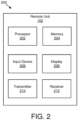
- Figure 2 depicts one embodiment of an apparatus 200 that may be used for flexible uplink/downlink transmissions.
- the apparatus 200 includes one embodiment of the remote unit 102.
- the remote unit 102 may include a processor 202, a memory 204, an input device 206, a display 208, a transmitter 210, and a receiver 212.
- the input device 206 and the display 208 are combined into a single device, such as a touchscreen.
- the processor 202 may include any known controller capable of executing computer-readable instructions and/or capable of performing logical operations.
- the processor 202 may be a microcontroller, a microprocessor, a central processing unit (“CPU"), a graphics processing unit (“GPU”), an auxiliary processing unit, a field programmable gate array (“FPGA”), or similar programmable controller.
- the processor 202 executes instructions stored in the memory 204 to perform the methods and routines described herein.
- the processor 202 is communicatively coupled to the memory 204, the input device 206, the display 208, the transmitter 210, and the receiver 212.
- the memory 204 in one embodiment, is a computer readable storage medium.
- the memory 204 includes volatile computer storage media.
- the memory 204 may include a RAM, including dynamic RAM (“DRAM”), synchronous dynamic RAM (“SDRAM”), and/or static RAM (“SRAM”).
- the memory 204 includes non-volatile computer storage media.
- the memory 204 may include a hard disk drive, a flash memory, or any other suitable non-volatile computer storage device.
- the memory 204 includes both volatile and non-volatile computer storage media.
- the memory 204 stores data relating to frame period lengths and/or uplink/downlink split patterns.
- the memory 204 also stores program code and related data, such as an operating system or other controller algorithms operating on the remote unit 102.
- the input device 206 may include any known computer input device including a touch panel, a button, a keyboard, a stylus, a microphone, or the like.
- the input device 206 may be integrated with the display 208, for example, as a touchscreen or similar touch-sensitive display.
- the input device 206 includes a touchscreen such that text may be input using a virtual keyboard displayed on the touchscreen and/or by handwriting on the touchscreen.
- the input device 206 includes two or more different devices, such as a keyboard and a touch panel.
- the display 208 may include any known electronically controllable display or display device.
- the display 208 may be designed to output visual, audible, and/or haptic signals.
- the display 208 includes an electronic display capable of outputting visual data to a user.
- the display 208 may include, but is not limited to, an LCD display, an LED display, an OLED display, a projector, or similar display device capable of outputting images, text, or the like to a user.
- the display 208 may include a wearable display such as a smart watch, smart glasses, a heads-up display, or the like.
- the display 208 may be a component of a smart phone, a personal digital assistant, a television, a table computer, a notebook (laptop) computer, a personal computer, a vehicle dashboard, or the like.
- the display 208 includes one or more speakers for producing sound.
- the display 208 may produce an audible alert or notification (e.g., a beep or chime).
- the display 208 includes one or more haptic devices for producing vibrations, motion, or other haptic feedback.
- all or portions of the display 208 may be integrated with the input device 206.
- the input device 206 and display 208 may form a touchscreen or similar touch-sensitive display.
- the display 208 may be located near the input device 206.
- the transmitter 210 is used to provide UL communication signals to the base unit 104 and the receiver 212 is used to receive DL communication signals from the base unit 104.
- the transmitter 210 is used to transmit LTL subframes based on a frame period length and an uplink/downlink split pattern.
- the receiver 212 may receive at least one message sent by the base unit 104.
- the receiver 212 may receive DL subframes based on the frame period length and the uplink/downlink split pattern.
- the remote unit 102 may have any suitable number of transmitters 210 and receivers 212.
- the transmitter 210 and the receiver 212 may be any suitable type of transmitters and receivers.
- the transmitter 210 and the receiver 212 may be part of a transceiver.
- Figure 3 depicts another embodiment of an apparatus 300 that may be used for flexible uplink/downlink transmissions.
- the apparatus 300 includes one embodiment of the base unit 104.
- the base unit 104 may include a processor 302, a memory 304, an input device 306, a display 308, a transmitter 310, and a receiver 312.
- the processor 302, the memory 304, the input device 306, and the display 308 may be substantially similar to the processor 202, the memory 204, the input device 206, and the display 208 of the remote unit 102, respectively.
- the transmitter 310 is used to provide DL communication signals to the remote unit 102 and the receiver 312 is used to receive UL communication signals from the remote unit 102. In one embodiment, the transmitter 310 is used to provide at least one message to the remote unit 102 (e.g., UE). Although only one transmitter 310 and one receiver 312 are illustrated, the base unit 104 may have any suitable number of transmitters 310 and receivers 312. The transmitter 310 and the receiver 312 may be any suitable type of transmitters and receivers. In one embodiment, the transmitter 310 and the receiver 312 may be part of a transceiver.
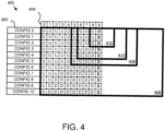
- Figure 4 depicts one embodiment of uplink/downlink split patterns 400 that facilitate flexible uplink/downlink transmissions.
- the uplink/downlink split patterns 400 include up to eleven split pattern configurations 402 (e.g., config 0, config 1, config 2, config 3, config 4, config 5, config 6, config 7, config 8, config 9, and config 10). Certain embodiments may include a greater number or fewer number of configurations.
- Each split pattern configuration 402 may include up to ten subframes 404 (e.g., subframes 0, 1, 2, 3, 4, 5, 6, 7, 8, and 9) in the illustrated embodiment; however, other embodiments may include a greater number of subframes.
- the base unit 104 may select the split pattern configuration 402 to use, such as based on an amount of LTL and DL traffic.
- the base unit 104 may also select a frame period length to be used with the split pattern configuration 402. For example, the base unit 104 may select a first frame period length 406 that is 10 ms and includes ten subframes. Furthermore, the base unit 104 may select a second frame period length 408 that is 5 ms and includes five subframes. Although the subframes 404 for the second frame period length 408 are labeled as "5" through “9,” they may actually be considered as subframes "0" through “4.” Moreover, the base unit 104 may select a third frame period length 410 that is 4 ms and includes four subframes.
- the base unit 104 may select a fourth frame period length 412 that is 2 ms and includes two subframes. Although the subframes 404 for the fourth frame period length 412 are labeled as "8" and “9,” they may actually be considered as subframes "0" and "1.” Even though they are not illustrated, there may be other frame period lengths, such as 1 ms, 3 ms, 6 ms, 7 ms, 8 ms, 9 ms, and so forth.
- split pattern configurations 402 are explained in greater detail below. For each of the split pattern configurations 402, any UL subframes are grouped together and occur before any DL subframes, which are also grouped together. Moreover, for each frame period length, the first split pattern configuration 402 includes only UL data and the last split pattern configuration 402 includes only DL data. Specifically, the "config 0" split pattern configuration 402 includes only LTL data.
- UL data occupies only a part of the subframe because at least 5% of the maximum channel occupancy time is reserved as an idle period at the end of this subframe.
- the length of the idle period depends on the FBE frame period length. For example, if the frame period length is 10 ms, the idle period may be 7 OFDM symbols.
- the "config 1" split pattern configuration 402 includes UL data followed by one subframe of DL data in the labeled subframe 9. For example, for the first frame period length 406, there are nine UL subframes followed by one DL subframe. As another example, for the second frame period length 408, there are four UL subframes followed by one DL subframe. Furthermore, for the third frame period length 410, there are three UL subframes followed by one DL subframe, and for the fourth frame period length 412, there is one UL subframe followed by one DL subframe.
- subframe 9 will be used for DL data.
- the DL data in subframe 9 may occupy either a full subframe or a partial subframe.
- DL data in subframe 9 occupies a full subframe if DL transmission is continued in a next frame period or if the base unit 104 does not schedule any UL transmission in the next frame period.
- DL data in subframe 9 occupies a partial subframe with at least one symbol muted for the remote unit 102 to perform a CCA check and/or RX-TX switching if the base unit 104 has scheduled any UL transmissions in the next frame period.
- the DL data in subframe 9 may always occupy a partial subframe in which at least one symbol is muted to facilitate the remote unit 102 performing the CCA check and/or RX-TX switching.
- the DL data in subframe 9 may occupy a full subframe if the uplink/downlink pattern in the next frame period includes only DL data (e.g., config 10), otherwise the DL data in subframe 9 may occupy a partial subframe.
- the base unit 104 may indicate to the remote unit 102 whether the DL data in subframe 9 is to occupy a full subframe or a partial subframe, such as via one-bit signaling (e.g., "0" for full DL subframe, "1" for partial DL subframe, or vice versa) in DL grant signaling.
- one-bit signaling e.g., "0" for full DL subframe, "1" for partial DL subframe, or vice versa
- the "config 2" split pattern configuration 402 includes, for the first frame period length 406, eight LTL subframes followed by two DL subframes, for the second frame period length 408, three UL subframes followed by two DL subframes, for the third frame period length 410, two UL subframes followed by two DL subframes, and for the fourth frame period length 412, two DL subframes.
- the "config 3" split pattern configuration 402 includes, for the first frame period length 406, seven LTL subframes followed by three DL subframes, for the second frame period length 408, two UL subframes followed by three DL subframes, and for the third frame period length 410, one UL subframe followed by three DL subframes.
- the "config 4" split pattern configuration 402 includes, for the first frame period length 406, six UL subframes followed by four DL subframes, for the second frame period length 408, one UL subframe followed by four DL subframes, and for the third frame period length 410, four DL subframes.
- the "config 5" split pattern configuration 402 includes, for the first frame period length 406, five UL subframes followed by five DL subframes, and for the second frame period length 408, five DL subframes.
- the "config 6" split pattern configuration 402 includes, for the first frame period length 406, four UL subframes followed by six DL subframes.
- the "config 7" split pattern configuration 402 includes, for the first frame period length 406, three UL subframes followed by seven DL subframes.
- the "config 8" split pattern configuration 402 includes, for the first frame period length 406, two LTL subframes followed by eight DL subframes.
- the "config 9” split pattern configuration 402 includes, for the first frame period length 406, one UL subframe followed by nine DL subframes.
- the "config 10" split pattern configuration 402 includes, for the first frame period length 406, ten DL subframes.
- the possible frame period lengths may be configured by RRC signaling and the starting subframe of the frame period may be aligned with PCell subframe 0.
- the frame period may be indicated by a L1 signaling to facilitate adjusting the length of the FBE frame period during operation. By adjusting the length of the FBE frame period during operation, UL transmission opportunity may be improved and the overhead of the FBE idle period may be decreased, in certain embodiments.
- L1 signaling is transmitted in CSS of PCell in the first subframe of each frame period.
- the L1 signaling may be fixed in PCell subframe 0 or 5 in each radio frame for simplicity.
- a new FBE frame period may take effect in the next radio frame after a current frame period finishes.
- the selected uplink/downlink split pattern may also be indicated in the L1 signaling to flexibly adjust the UL and DL resource ratio. In this way, high throughput gain may be achieved due to traffic adaptation.
- the L1 signaling or other signaling that indicates the frame period length and the uplink/downlink split pattern is transmitted at least 4 ms before the start of a new FBE frame period.
- Figure 5 is a schematic block diagram illustrating one embodiment of at least one message 500 transmitted from a base unit 104 to a remote unit 102.
- the at least one message 500 includes a frame period length 502, a config number 504, and a last subframe indicator 506.
- the at least one message 500 may be one or more messages, even though the at least one message 500 is illustrated as being one message.
- the at least one message 500 may be part of L1 signaling and/or uplink/downlink grant messaging.
- the frame period length 502 is used to indicate a frame period length for the next frame following the frame in which the frame period length 502 is received.
- the frame period length may be 1 ms, 2 ms, 3 ms, 4 ms, 5 ms, 6 ms, 7 ms, 8 ms, 9 ms, 10 ms, and so forth.
- the frame period length 502 may be changed as often as desired to adjust the frame period length. For example, the frame period length 502 may be changed as often as each frame.
- the config number 504 may be any suitable representation of one of the split pattern configurations 402. In certain embodiments, the config number 504 may be an actual number that represents a stored number corresponding to a configuration, such as the configuration numbers presented above.
- the last subframe indicator 506 may be any indicator used to indicate whether the last DL subframe in a DL transmission is to be a full subframe for DL transmission or a partial subframe for DL transmission.
- the last subframe indicator 506 may be a bit in DL grant signaling that indicates whether the last DL subframe in a DL transmission is to be a full subframe for DL transmission or a partial subframe for DL transmission (e.g., "0" for full DL subframe, "1" for partial DL subframe, or vice versa).
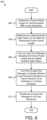
- Figure 6 is a schematic flow chart diagram illustrating one embodiment of a method 600 for a base unit 104 to receive flexible UL transmissions from a remote unit 102 and to provide flexible DL transmissions to the remote unit 102.
- the method 600 is performed by an apparatus, such as the base unit 104.
- the method 600 may be performed by a processor executing program code, for example, a microcontroller, a microprocessor, a CPU, a GPU, an auxiliary processing unit, a FPGA, or the like.
- the method 600 may include determining 602 a frame period length (e.g., frame period lengths 406, 408, 410, 412) for communication with a remote unit 102 (e.g., a UE).
- the base unit 104 may determine 602 the frame period length for communication with the remote unit 102.
- determining the frame period length for communication with the remote unit 102 may include selecting the frame period length from a group of frame period lengths (e.g., 1 ms, 2 ms, 3 ms, 4 ms, 5 ms, 6 ms, 7 ms, 8 ms, 9 ms, 10 ms, and so forth).
- the method 600 may also include determining 604 an uplink/downlink split pattern (e.g., split pattern configurations 402) to use with the determined frame period length.
- the base unit 104 may determine 604 the uplink/downlink split pattern to use based on the determined frame period length.
- determining 604 the uplink/downlink split pattern to use with the frame period length includes selecting the uplink/downlink split pattern from a group of uplink/downlink split patterns (e.g., split pattern configurations 402).
- the group of uplink/downlink split patterns may include: a first pattern including ten UL subframes; a second pattern including nine UL subframes followed by one DL subframe; a third pattern including eight LTL subframes followed by two DL subframes; a fourth pattern including seven UL subframes followed by three DL subframes; a fifth pattern including six UL subframes followed by four DL subframes; a sixth pattern including five LTL subframes followed by five DL subframes; a seventh pattern including four UL subframes followed by six DL subframes; an eighth pattern including three UL subframes followed by seven DL subframes; a ninth pattern including two UL subframes followed by eight DL subframes; a tenth pattern including one UL subframe followed by nine DL subframes; and an eleventh pattern including ten DL subframes.
- each uplink/downlink split pattern includes consecutive UL subframes grouped together and consecutive DL subframes grouped together. In some embodiments, there is no gap between the UL and DL subframes.
- the uplink/downlink split pattern is indicated in DL grant signaling or UL grant signaling to one remote unit 102, while in another embodiment, the uplink/downlink split pattern is indicated in CSS of predefined subframes of one predefined licensed carrier to more than one remote unit 102.
- each uplink/downlink split pattern begins with a UL subframe (if the split pattern includes a UL subframe).
- the method 600 may include forming 606 at least one message (e.g., the at least one message 500) indicating the frame period length and the uplink/downlink split pattern.
- the base unit 104 may form 606 the at least one message indicating the frame period length and the uplink/downlink split pattern.
- forming 606 the at least one message indicating the frame period length and the uplink/downlink split pattern includes forming an L1 signaling message indicating the frame period length and the uplink/downlink split pattern.
- the method 600 may also include forming 608 the at least one message to indicate whether a last DL subframe in a frame period is a full subframe for DL transmission or a partial subframe for DL transmission.
- the base unit 104 may form 608 the at least one message to indicate whether the last DL subframe in the frame period is a full subframe for DL transmission or a partial subframe for DL transmission.
- a DL grant message includes a bit to indicate whether the last DL subframe in the frame period is a full subframe for DL transmission or a partial subframe for DL transmission.
- the method 600 may include determining whether the last DL subframe in the frame period is a full subframe for DL transmission or a partial subframe for DL transmission.
- the last DL subframe in the frame period is determined to be a full subframe for DL transmission if a first subframe in a next frame period that follows the frame period is a DL subframe and the last DL subframe in the frame period is determined to be a partial subframe for DL transmission if the first subframe in the next frame is a UL subframe.
- the method 600 may provide 610 the at least one message to the remote unit 102. Then the method 600 may end.
- the transmitter 310 of the base unit 104 may provide 610 the at least one message to the remote unit 102.
- providing 610 the at least one message to the remote unit 102 may include providing the at least one message to the remote unit 102 at least four ms before a first subframe in a frame period that is to implement the frame period length and the uplink/downlink split pattern.
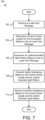
- Figure 7 is a schematic flow chart diagram illustrating one embodiment of a method 700 for a remote unit 102 to receive flexible DL transmissions from a base unit 104 and to provide flexible UL transmissions to the base unit 104.
- the method 700 is performed by an apparatus, such as the remote unit 102.
- the method 700 may be performed by a processor executing program code, for example, a microcontroller, a microprocessor, a CPU, a GPU, an auxiliary processing unit, a FPGA, or the like.
- the method 700 may include receiving 702 at least one message (e.g., the at least one message 500). In one embodiment, the receiver 212 of the remote unit 102 may receive the at least one message. The method 700 may also include determining 704 a frame period length (e.g., frame period lengths 406, 408, 410, 412) for communication based on the at least one message. In one embodiment, the remote unit 102 determines 704 the frame period length for communication based on the at least one message.
- a frame period length e.g., frame period lengths 406, 408, 410, 412
- the method 700 may include determining 706 an uplink/downlink split pattern (e.g., split pattern configurations 402) based on the at least one message.
- the remote unit 102 may determine 706 the uplink/downlink split pattern based on the at least one message.
- the uplink/downlink split pattern includes consecutive UL subframes grouped together and consecutive DL subframes grouped together. In certain embodiments, there is no gap between the UL subframes and the DL subframes.
- the uplink/downlink split pattern is indicated in DL grant signaling or UL grant signaling to one remote unit 102, while in other embodiments, the uplink/downlink split pattern is indicated in CSS of predefined subframes of one predefined licensed carrier to more than one remote unit 102.
- the at least one message indicates whether a last DL subframe in a frame period is a full subframe for DL transmission or a partial subframe for DL transmission.
- the method 700 may include transmitting 708 UL subframes based on the frame period length and the uplink/downlink split pattern.
- the transmitter 210 of the remote unit 102 may transmit 708 UL subframes based on the frame period length and the uplink/downlink split pattern.
- the method 700 may also include receiving 710 DL subframes based on the frame period length and the uplink/downlink split pattern. Then the method 700 may end.
- the receiver 212 may receive 710 DL subframes based on the frame period length and the uplink/downlink split pattern.
Landscapes
- Engineering & Computer Science (AREA)
- Computer Networks & Wireless Communication (AREA)
- Signal Processing (AREA)
- Quality & Reliability (AREA)
- Mobile Radio Communication Systems (AREA)
Priority Applications (1)
| Application Number | Priority Date | Filing Date | Title |
|---|---|---|---|
| EP23190554.8A EP4247096A3 (fr) | 2015-08-14 | 2015-08-14 | Transmissions flexibles de liaison montante/descendante dans un système de communication sans fil |
Applications Claiming Priority (3)
| Application Number | Priority Date | Filing Date | Title |
|---|---|---|---|
| EP15901205.3A EP3320731B1 (fr) | 2015-08-14 | 2015-08-14 | Transmissions en liaison montante/descendante flexibles dans un système de communication sans fil |
| EP23190554.8A EP4247096A3 (fr) | 2015-08-14 | 2015-08-14 | Transmissions flexibles de liaison montante/descendante dans un système de communication sans fil |
| PCT/CN2015/086925 WO2017027999A1 (fr) | 2015-08-14 | 2015-08-14 | Transmissions en liaison montante/descendante flexibles dans un système de communication sans fil |
Related Parent Applications (2)
| Application Number | Title | Priority Date | Filing Date |
|---|---|---|---|
| EP15901205.3A Division-Into EP3320731B1 (fr) | 2015-08-14 | 2015-08-14 | Transmissions en liaison montante/descendante flexibles dans un système de communication sans fil |
| EP15901205.3A Division EP3320731B1 (fr) | 2015-08-14 | 2015-08-14 | Transmissions en liaison montante/descendante flexibles dans un système de communication sans fil |
Publications (2)
| Publication Number | Publication Date |
|---|---|
| EP4247096A2 true EP4247096A2 (fr) | 2023-09-20 |
| EP4247096A3 EP4247096A3 (fr) | 2023-11-22 |
Family
ID=58050537
Family Applications (2)
| Application Number | Title | Priority Date | Filing Date |
|---|---|---|---|
| EP23190554.8A Pending EP4247096A3 (fr) | 2015-08-14 | 2015-08-14 | Transmissions flexibles de liaison montante/descendante dans un système de communication sans fil |
| EP15901205.3A Active EP3320731B1 (fr) | 2015-08-14 | 2015-08-14 | Transmissions en liaison montante/descendante flexibles dans un système de communication sans fil |
Family Applications After (1)
| Application Number | Title | Priority Date | Filing Date |
|---|---|---|---|
| EP15901205.3A Active EP3320731B1 (fr) | 2015-08-14 | 2015-08-14 | Transmissions en liaison montante/descendante flexibles dans un système de communication sans fil |
Country Status (5)
| Country | Link |
|---|---|
| US (3) | US10623135B2 (fr) |
| EP (2) | EP4247096A3 (fr) |
| KR (1) | KR102043842B1 (fr) |
| CN (1) | CN107925993B (fr) |
| WO (1) | WO2017027999A1 (fr) |
Families Citing this family (3)
| Publication number | Priority date | Publication date | Assignee | Title |
|---|---|---|---|---|
| US10623135B2 (en) * | 2015-08-14 | 2020-04-14 | Lenovo Innovations Limited (Hong Kong) | Flexible uplink/downlink transmissions in a wireless communication system |
| US11115161B2 (en) * | 2018-05-02 | 2021-09-07 | Qualcomm Incorporated | Transmission diversity for FBE idle period handling |
| US11764908B2 (en) | 2020-07-31 | 2023-09-19 | Electronics And Telecommunications Research Institute | Method and apparatus for transmitting a HARQ codebook based on reference time |
Family Cites Families (19)
| Publication number | Priority date | Publication date | Assignee | Title |
|---|---|---|---|---|
| US8159979B2 (en) * | 2008-01-11 | 2012-04-17 | Lg Electronics Inc. | Enhanced TDD frame structure |
| CN102349347B (zh) | 2009-01-27 | 2014-12-24 | 诺基亚公司 | 动态地修改传输帧的方法和设备 |
| US8559343B2 (en) | 2009-12-23 | 2013-10-15 | Telefonaktiebolaget Lm Ericsson (Publ) | Flexible subframes |
| EP2604081A4 (fr) * | 2010-08-12 | 2016-10-19 | Nokia Technologies Oy | Configuration d'un schéma de division de liaison montante et de liaison descendante pour une communication entre dispositifs (d2d) dans un réseau cellulaire |
| CN102158325B (zh) * | 2011-04-22 | 2017-05-10 | 中兴通讯股份有限公司 | 数据传输方法及装置 |
| KR102031031B1 (ko) * | 2011-06-20 | 2019-10-15 | 삼성전자 주식회사 | 무선 통신 시스템에서 시분할 복식 프레임 구성 정보 송수신 방법 및 장치 |
| BR112014003579A2 (pt) * | 2011-08-15 | 2017-03-14 | Nokia Solutions & Networks Oy | sinalização |
| CN103108328B (zh) | 2011-11-11 | 2016-05-25 | 中国移动通信集团公司 | 动态时隙配比方法、基站、终端和系统 |
| US9119120B2 (en) * | 2012-01-23 | 2015-08-25 | Intel Corporation | Network assisted user association and offloading techniques for integrated multi-rat heterogeneous networks |
| US9119074B2 (en) * | 2012-06-05 | 2015-08-25 | Qualcomm Incorporated | Uplink downlink resource partitions in access point design |
| US9078275B2 (en) * | 2012-09-05 | 2015-07-07 | Mediatek Inc. | Bluetooth low energy and LTE coexistence enhancements |
| KR20140040445A (ko) * | 2012-09-26 | 2014-04-03 | 주식회사 팬택 | 교차 반송파 스케줄링에서 불연속 수신 장치 및 방법 |
| WO2014110782A1 (fr) | 2013-01-18 | 2014-07-24 | Broadcom Corporation | Configuration basée sur un regroupement cellulaire de communication à duplexage par répartition temporelle flexible |
| WO2014161174A1 (fr) * | 2013-04-03 | 2014-10-09 | Nokia Siemens Networks Oy | Configuration de liaison montante-liaison descendante dynamique |
| US9591644B2 (en) * | 2013-08-16 | 2017-03-07 | Qualcomm Incorporated | Downlink procedures for LTE/LTE-A communication systems with unlicensed spectrum |
| KR102221332B1 (ko) * | 2013-11-13 | 2021-03-02 | 삼성전자 주식회사 | 이동 통신 시스템에서 파워 헤드룸 보고 및 하이브리드 자동 재전송을 제어하는 방법 및 장치 |
| ES2644608T3 (es) * | 2013-12-04 | 2017-11-29 | Telefonaktiebolaget Lm Ericsson (Publ) | Reducción de sub-trama de enlace descendente en sistemas de dúplex por división de tiempo (TDD) |
| EP3259950B1 (fr) * | 2015-02-20 | 2019-09-18 | Telefonaktiebolaget LM Ericsson (publ) | Diagrammes lbt pour communication sans fil |
| US10623135B2 (en) * | 2015-08-14 | 2020-04-14 | Lenovo Innovations Limited (Hong Kong) | Flexible uplink/downlink transmissions in a wireless communication system |
-
2015
- 2015-08-14 US US15/752,534 patent/US10623135B2/en active Active
- 2015-08-14 EP EP23190554.8A patent/EP4247096A3/fr active Pending
- 2015-08-14 CN CN201580082113.3A patent/CN107925993B/zh active Active
- 2015-08-14 KR KR1020187003896A patent/KR102043842B1/ko active IP Right Grant
- 2015-08-14 WO PCT/CN2015/086925 patent/WO2017027999A1/fr active Application Filing
- 2015-08-14 EP EP15901205.3A patent/EP3320731B1/fr active Active
-
2020
- 2020-04-08 US US16/843,302 patent/US10985865B2/en active Active
-
2021
- 2021-03-17 US US17/204,737 patent/US11456816B2/en active Active
Also Published As
| Publication number | Publication date |
|---|---|
| EP3320731B1 (fr) | 2023-11-01 |
| CN107925993B (zh) | 2022-05-31 |
| EP4247096A3 (fr) | 2023-11-22 |
| CN107925993A (zh) | 2018-04-17 |
| US20190013898A1 (en) | 2019-01-10 |
| US20200235846A1 (en) | 2020-07-23 |
| EP3320731A1 (fr) | 2018-05-16 |
| EP3320731A4 (fr) | 2019-02-27 |
| US20210203441A1 (en) | 2021-07-01 |
| KR20180031000A (ko) | 2018-03-27 |
| WO2017027999A1 (fr) | 2017-02-23 |
| US11456816B2 (en) | 2022-09-27 |
| EP3320731C0 (fr) | 2023-11-01 |
| KR102043842B1 (ko) | 2019-11-12 |
| US10985865B2 (en) | 2021-04-20 |
| US10623135B2 (en) | 2020-04-14 |
Similar Documents
| Publication | Publication Date | Title |
|---|---|---|
| US11825478B2 (en) | Uplink/downlink scheduling in a wireless communication system | |
| US11968687B2 (en) | Scheduling of transmission time intervals | |
| EP4169344A1 (fr) | Partage de temps d'occupation de canal | |
| US11456816B2 (en) | Flexible uplink/downlink transmissions in a wireless communication system | |
| WO2022153222A1 (fr) | Configuration d'un groupement de signaux de référence de démodulation et d'une programmation de bloc de transport | |
| US10736133B2 (en) | Burst-based transmission scheduling in a wireless communication system | |
| WO2021260604A1 (fr) | Transmissions de canal physique partagé descendant se chevauchant | |
| EP4136784A1 (fr) | Traitement et rapport d'informations d'état de canal |
Legal Events
| Date | Code | Title | Description |
|---|---|---|---|
| PUAI | Public reference made under article 153(3) epc to a published international application that has entered the european phase |
Free format text: ORIGINAL CODE: 0009012 |
|
| STAA | Information on the status of an ep patent application or granted ep patent |
Free format text: STATUS: THE APPLICATION HAS BEEN PUBLISHED |
|
| AC | Divisional application: reference to earlier application |
Ref document number: 3320731 Country of ref document: EP Kind code of ref document: P |
|
| AK | Designated contracting states |
Kind code of ref document: A2 Designated state(s): AL AT BE BG CH CY CZ DE DK EE ES FI FR GB GR HR HU IE IS IT LI LT LU LV MC MK MT NL NO PL PT RO RS SE SI SK SM TR |
|
| REG | Reference to a national code |
Ref country code: DE Ref legal event code: R079 Free format text: PREVIOUS MAIN CLASS: H04W0072230000 Ipc: H04W0072044600 |
|
| PUAL | Search report despatched |
Free format text: ORIGINAL CODE: 0009013 |
|
| AK | Designated contracting states |
Kind code of ref document: A3 Designated state(s): AL AT BE BG CH CY CZ DE DK EE ES FI FR GB GR HR HU IE IS IT LI LT LU LV MC MK MT NL NO PL PT RO RS SE SI SK SM TR |
|
| RIC1 | Information provided on ipc code assigned before grant |
Ipc: H04W 72/23 20230101ALN20231017BHEP Ipc: H04W 72/0446 20230101AFI20231017BHEP |
|
| STAA | Information on the status of an ep patent application or granted ep patent |
Free format text: STATUS: REQUEST FOR EXAMINATION WAS MADE |
|
| 17P | Request for examination filed |
Effective date: 20240517 |
|
| RBV | Designated contracting states (corrected) |
Designated state(s): AL AT BE BG CH CY CZ DE DK EE ES FI FR GB GR HR HU IE IS IT LI LT LU LV MC MK MT NL NO PL PT RO RS SE SI SK SM TR |