EP4246999A1 - Audio device - Google Patents
Audio device Download PDFInfo
- Publication number
- EP4246999A1 EP4246999A1 EP21891607.0A EP21891607A EP4246999A1 EP 4246999 A1 EP4246999 A1 EP 4246999A1 EP 21891607 A EP21891607 A EP 21891607A EP 4246999 A1 EP4246999 A1 EP 4246999A1
- Authority
- EP
- European Patent Office
- Prior art keywords
- reflective
- audio device
- acoustic channel
- sound
- communication hole
- Prior art date
- Legal status (The legal status is an assumption and is not a legal conclusion. Google has not performed a legal analysis and makes no representation as to the accuracy of the status listed.)
- Pending
Links
Images



Classifications
-
- G—PHYSICS
- G10—MUSICAL INSTRUMENTS; ACOUSTICS
- G10K—SOUND-PRODUCING DEVICES; METHODS OR DEVICES FOR PROTECTING AGAINST, OR FOR DAMPING, NOISE OR OTHER ACOUSTIC WAVES IN GENERAL; ACOUSTICS NOT OTHERWISE PROVIDED FOR
- G10K11/00—Methods or devices for transmitting, conducting or directing sound in general; Methods or devices for protecting against, or for damping, noise or other acoustic waves in general
- G10K11/16—Methods or devices for protecting against, or for damping, noise or other acoustic waves in general
- G10K11/172—Methods or devices for protecting against, or for damping, noise or other acoustic waves in general using resonance effects
-
- H—ELECTRICITY
- H04—ELECTRIC COMMUNICATION TECHNIQUE
- H04R—LOUDSPEAKERS, MICROPHONES, GRAMOPHONE PICK-UPS OR LIKE ACOUSTIC ELECTROMECHANICAL TRANSDUCERS; ELECTRIC HEARING AIDS; PUBLIC ADDRESS SYSTEMS
- H04R1/00—Details of transducers, loudspeakers or microphones
- H04R1/20—Arrangements for obtaining desired frequency or directional characteristics
- H04R1/22—Arrangements for obtaining desired frequency or directional characteristics for obtaining desired frequency characteristic only
- H04R1/28—Transducer mountings or enclosures modified by provision of mechanical or acoustic impedances, e.g. resonator, damping means
- H04R1/2807—Enclosures comprising vibrating or resonating arrangements
- H04R1/2853—Enclosures comprising vibrating or resonating arrangements using an acoustic labyrinth or a transmission line
- H04R1/2857—Enclosures comprising vibrating or resonating arrangements using an acoustic labyrinth or a transmission line for loudspeaker transducers
-
- G—PHYSICS
- G10—MUSICAL INSTRUMENTS; ACOUSTICS
- G10K—SOUND-PRODUCING DEVICES; METHODS OR DEVICES FOR PROTECTING AGAINST, OR FOR DAMPING, NOISE OR OTHER ACOUSTIC WAVES IN GENERAL; ACOUSTICS NOT OTHERWISE PROVIDED FOR
- G10K11/00—Methods or devices for transmitting, conducting or directing sound in general; Methods or devices for protecting against, or for damping, noise or other acoustic waves in general
- G10K11/02—Mechanical acoustic impedances; Impedance matching, e.g. by horns; Acoustic resonators
-
- G—PHYSICS
- G10—MUSICAL INSTRUMENTS; ACOUSTICS
- G10K—SOUND-PRODUCING DEVICES; METHODS OR DEVICES FOR PROTECTING AGAINST, OR FOR DAMPING, NOISE OR OTHER ACOUSTIC WAVES IN GENERAL; ACOUSTICS NOT OTHERWISE PROVIDED FOR
- G10K11/00—Methods or devices for transmitting, conducting or directing sound in general; Methods or devices for protecting against, or for damping, noise or other acoustic waves in general
- G10K11/18—Methods or devices for transmitting, conducting or directing sound
- G10K11/20—Reflecting arrangements
-
- G—PHYSICS
- G10—MUSICAL INSTRUMENTS; ACOUSTICS
- G10K—SOUND-PRODUCING DEVICES; METHODS OR DEVICES FOR PROTECTING AGAINST, OR FOR DAMPING, NOISE OR OTHER ACOUSTIC WAVES IN GENERAL; ACOUSTICS NOT OTHERWISE PROVIDED FOR
- G10K11/00—Methods or devices for transmitting, conducting or directing sound in general; Methods or devices for protecting against, or for damping, noise or other acoustic waves in general
- G10K11/18—Methods or devices for transmitting, conducting or directing sound
- G10K11/22—Methods or devices for transmitting, conducting or directing sound for conducting sound through hollow pipes, e.g. speaking tubes
-
- H—ELECTRICITY
- H04—ELECTRIC COMMUNICATION TECHNIQUE
- H04R—LOUDSPEAKERS, MICROPHONES, GRAMOPHONE PICK-UPS OR LIKE ACOUSTIC ELECTROMECHANICAL TRANSDUCERS; ELECTRIC HEARING AIDS; PUBLIC ADDRESS SYSTEMS
- H04R1/00—Details of transducers, loudspeakers or microphones
- H04R1/02—Casings; Cabinets ; Supports therefor; Mountings therein
- H04R1/025—Arrangements for fixing loudspeaker transducers, e.g. in a box, furniture
-
- H—ELECTRICITY
- H04—ELECTRIC COMMUNICATION TECHNIQUE
- H04R—LOUDSPEAKERS, MICROPHONES, GRAMOPHONE PICK-UPS OR LIKE ACOUSTIC ELECTROMECHANICAL TRANSDUCERS; ELECTRIC HEARING AIDS; PUBLIC ADDRESS SYSTEMS
- H04R1/00—Details of transducers, loudspeakers or microphones
- H04R1/20—Arrangements for obtaining desired frequency or directional characteristics
- H04R1/22—Arrangements for obtaining desired frequency or directional characteristics for obtaining desired frequency characteristic only
- H04R1/28—Transducer mountings or enclosures modified by provision of mechanical or acoustic impedances, e.g. resonator, damping means
- H04R1/2807—Enclosures comprising vibrating or resonating arrangements
- H04R1/2811—Enclosures comprising vibrating or resonating arrangements for loudspeaker transducers
-
- H—ELECTRICITY
- H04—ELECTRIC COMMUNICATION TECHNIQUE
- H04R—LOUDSPEAKERS, MICROPHONES, GRAMOPHONE PICK-UPS OR LIKE ACOUSTIC ELECTROMECHANICAL TRANSDUCERS; ELECTRIC HEARING AIDS; PUBLIC ADDRESS SYSTEMS
- H04R1/00—Details of transducers, loudspeakers or microphones
- H04R1/20—Arrangements for obtaining desired frequency or directional characteristics
- H04R1/22—Arrangements for obtaining desired frequency or directional characteristics for obtaining desired frequency characteristic only
- H04R1/28—Transducer mountings or enclosures modified by provision of mechanical or acoustic impedances, e.g. resonator, damping means
- H04R1/2869—Reduction of undesired resonances, i.e. standing waves within enclosure, or of undesired vibrations, i.e. of the enclosure itself
- H04R1/2876—Reduction of undesired resonances, i.e. standing waves within enclosure, or of undesired vibrations, i.e. of the enclosure itself by means of damping material, e.g. as cladding
- H04R1/288—Reduction of undesired resonances, i.e. standing waves within enclosure, or of undesired vibrations, i.e. of the enclosure itself by means of damping material, e.g. as cladding for loudspeaker transducers
-
- H—ELECTRICITY
- H04—ELECTRIC COMMUNICATION TECHNIQUE
- H04R—LOUDSPEAKERS, MICROPHONES, GRAMOPHONE PICK-UPS OR LIKE ACOUSTIC ELECTROMECHANICAL TRANSDUCERS; ELECTRIC HEARING AIDS; PUBLIC ADDRESS SYSTEMS
- H04R1/00—Details of transducers, loudspeakers or microphones
- H04R1/20—Arrangements for obtaining desired frequency or directional characteristics
- H04R1/22—Arrangements for obtaining desired frequency or directional characteristics for obtaining desired frequency characteristic only
- H04R1/28—Transducer mountings or enclosures modified by provision of mechanical or acoustic impedances, e.g. resonator, damping means
- H04R1/2869—Reduction of undesired resonances, i.e. standing waves within enclosure, or of undesired vibrations, i.e. of the enclosure itself
- H04R1/2884—Reduction of undesired resonances, i.e. standing waves within enclosure, or of undesired vibrations, i.e. of the enclosure itself by means of the enclosure structure, i.e. strengthening or shape of the enclosure
- H04R1/2888—Reduction of undesired resonances, i.e. standing waves within enclosure, or of undesired vibrations, i.e. of the enclosure itself by means of the enclosure structure, i.e. strengthening or shape of the enclosure for loudspeaker transducers
-
- H—ELECTRICITY
- H04—ELECTRIC COMMUNICATION TECHNIQUE
- H04R—LOUDSPEAKERS, MICROPHONES, GRAMOPHONE PICK-UPS OR LIKE ACOUSTIC ELECTROMECHANICAL TRANSDUCERS; ELECTRIC HEARING AIDS; PUBLIC ADDRESS SYSTEMS
- H04R1/00—Details of transducers, loudspeakers or microphones
- H04R1/20—Arrangements for obtaining desired frequency or directional characteristics
- H04R1/32—Arrangements for obtaining desired frequency or directional characteristics for obtaining desired directional characteristic only
- H04R1/34—Arrangements for obtaining desired frequency or directional characteristics for obtaining desired directional characteristic only by using a single transducer with sound reflecting, diffracting, directing or guiding means
- H04R1/345—Arrangements for obtaining desired frequency or directional characteristics for obtaining desired directional characteristic only by using a single transducer with sound reflecting, diffracting, directing or guiding means for loudspeakers
Definitions
- the present invention relates to an audio device that suppresses distortion in sound pressure frequency response caused by standing waves occurring within a space.
- Patent Literature (PTL) 1 describes a technique in which an acoustic channel that communicates with a reflective space is provided in a loudspeaker cabinet in order to suppress the effects of standing waves occurring in the reflective space.
- the technique described in PTL 1 can suppress peaks in sound pressure at resonant frequencies through resonance occurring between the acoustic channel and the reflective space of the cabinet, the technique does not directly suppress dips in sound pressure frequency response.
- the present invention has been conceived in view of the above-mentioned problem and has an object to provide an audio device capable of achieving a sound pressure frequency response that has few dips and is as flat as possible.
- an audio device including a plurality of reflective components that reflect sound emitted from a loudspeaker unit, the audio device forming a reflective space surrounded by the plurality of reflective components, the audio device including: an acoustic channel that is tube-shaped and includes an opening on one end and a terminating portion on an other end, the one end being connected to a communication hole provided in a reflective component among the plurality of reflective components; and a sound absorbing material disposed at a central portion of a sound path formed by the acoustic channel.
- the sound absorbing material provided in the central portion of the acoustic channel can effectively suppress the amplitude of standing waves occurring within a reflective space, and thereby make it possible to flatten sound pressure frequency response.
- drawings are schematic illustrations, which may include emphasis, omission, or adjustment of proportion as necessary for the purpose of illustrating the present invention, and thus the shapes, positional relationships, and proportions shown may be different from actuality.
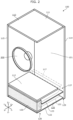
- FIG. 1 is a perspective view of the external appearance of an audio device according to an embodiment.
- FIG. 2 is a perspective view with a portion of the reflective components omitted illustrating the audio device according to the embodiment.
- Audio device 100 is a loudspeaker cabinet in a so-called loudspeaker system, and loudspeaker unit 200 is mounted to the device. Audio device 100 includes reflective components 110, acoustic channel 120, and sound absorbing material 130.
- Loudspeaker unit 200 is an electroacoustic conversion device that converts electrical signals, such as audio signals, into the vibrations of a diaphragm.
- the size, shape, and structure of the diaphragm, magnetic circuit, and frame, and the like, which loudspeaker unit 200 is composed of are not particularly limited.
- an electrodynamic loudspeaker that includes a cone-shaped diaphragm is used for loudspeaker unit 200.
- Reflective components 110 are components that reflect sound that is output from loudspeaker unit 200.
- the space surrounded by reflective components 110 is a reflective space in which the sound that is output by loudspeaker unit 200 is reflected.
- reflective components 110 are a plurality of board-shaped reflective components 110 that include top panel 111, bottom panel 112, front panel 113, rear panel 114, and two side panels 115, which are assembled in a rectangular-cuboid shape to form a rectangular cuboid-shaped reflective space 101.
- Mounting hole 116 is provided penetrating through front panel 113 that is one of reflective components 110, and loudspeaker unit 200 is mounted by being inserted into mounting hole 116.
- Communication hole 117 is provided penetrating through bottom panel 112 that is one of reflective components 110, thereby bringing reflective space 101 and sound path 121 into communication with each other.
- bottom panel 112 is shorter than top panel 111 in the depth-wise direction (X-axis direction in the figure), and the space surrounded by bottom panel 112, rear panel 114, and both side panels 115 defines communication hole 117.
- reflective components 110 there are no particular limitations on the material of reflective components 110, and examples include wood, resin, building materials, and ceramics, and the like, and multiple materials may be combined.
- Acoustic channel 120 is a tube-shaped portion that includes opening 127 on one end and terminating portion 129 on the other end, and acoustic channel 120 is a portion that forms sound path 121 that communicates with reflective space 101 formed by reflective components 110.
- the length of sound path 121 formed by acoustic channel 120 is not particularly limited and may be determined by the position of a dip occurring in sound pressure frequency response, or the like, due to distortion caused by the effects of reflective space 101 formed by reflective components 110, for example.
- acoustic channel 120 is set that forms sound path 121 having a length that is at least 50% of the length of distance from the reflective component 110 disposed opposite communication hole 117 to communication hole 117.
- the length of sound path 121 is set to be the same as the length of distance from top panel 111 to bottom panel 112.
- Sound absorbing material 130 is a component disposed at central portion 128 of sound path 121 formed by acoustic channel 120.
- sound absorbing material 130 there are no particular limitations on sound absorbing material 130 as long as the material can suppress vibrations in the air, and examples include an open-cell, sponge-like sound absorbing material 130, as well as a wool-type sound absorbing material 130 that is an aggregate of fiberglass and mineral wool, and the like.
- the position of sound absorbing material 130 is not particularly limited as long as it is at a central portion of sound path 121.
- sound absorbing material 130 may be disposed so as to obstruct acoustic channel 120, or sound absorbing material 130 may be attached to the inner surface of acoustic channel 120 so as not to obstruct acoustic channel 120.
- the placement position of sound absorbing material 130 inside of acoustic channel 120 can be said to constitute a region that includes a portion within acoustic channel 120 that has high particle velocity.
- acoustic channel 120 forms a sound path 121 of a length equivalent to or close to half a wavelength of the standing wave occurring within reflective space 101 that causes the dip to occur.
- a standing wave that vibrates in unison in the same frequency as the standing wave in reflective space 101 can be generated within acoustic channel 120.
- vibrations can be suppressed at the portion in acoustic channel 120 at which the particle velocity of standing waves is highest, and thus standing waves can effectively be suppressed. Consequently, the dip to be suppressed can selectively be suppressed without affecting sound pressure frequency response for other frequencies particularly the lower frequencies.
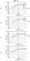
- FIG. 3 illustrates the sound pressure frequency response of an audio device 100 in which acoustic channel 120 is not provided, and in which communication hole 117 is not provided in reflective component 110.
- FIG. 3 illustrates the sound pressure frequency response of an audio device 100 in which acoustic channel 120 is connected to communication hole 117 of reflective component 110, and in which sound absorbing material 130 is not provided.
- FIG. 3 illustrates the sound pressure frequency response of audio device 100 according to the present embodiment.
- dips other than dip 301 also occur because acoustic channel 120 is connected to a rectangular cuboid-shaped reflective space 101. Sound pressure frequency response becomes more distorted than when acoustic channel 120 is not provided.
- dip 301 that occurs when acoustic channel 120 is not provided ((a) in FIG. 3 ) is significantly remedied, and sound pressure frequency response is smooth. Furthermore, the peak occurring in the higher frequency-side vicinity of dip 301 is also suppressed. Moreover, dips other than dip 301 that occur due to the presence of acoustic channel 120 are eliminated, and practically no effects can be observed in sound pressure frequency response on the lower frequency-side relative to dip 301.
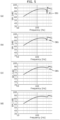
- the aperture area of communication hole 117 is within a range of from 5% to 50% of the surface area of the reflective component 110 on which communication hole 117 is provided (specifically, the surface area of such reflective component 110 when communication hole 117 is not provided) (see FIG. 4 ).
- the graph illustrated in (a) in FIG. 4 shows the sound pressure frequency response when the aperture area of communication hole 117 is less than 5% (specifically, 1%). This illustrates that it is difficult to suppress dip 301 with a communication hole 117 having such an aperture area.
- the graph illustrated in (b) in FIG. 4 shows the sound pressure frequency response when the aperture area of communication hole 117 is 5%.
- a communication hole 117 with such an aperture area can suppress dip 301 in the sound pressure frequency response.
- the graph illustrated in (c) in FIG. 4 shows the sound pressure frequency response when the aperture area of communication hole 117 is 10%.
- a communication hole 117 having such an aperture area can further suppress dip 301 in the sound pressure frequency response.
- the graph illustrated in (d) in FIG. 4 shows the sound pressure frequency response when the aperture area of communication hole 117 is 50%.
- the vicinity of dip 301 which is the target to be suppressed, can be rendered virtually flat. It should be noted that an aperture area of communication hole 117 larger than 50% would not be practical since the volume of the box that includes acoustic channel 120 would become large.
- FIG. 5 shows graphs illustrating sound pressure frequency response for sound paths with different lengths.
- the length of sound path 121 is less than 50% of half a wavelength (for example, 25% of half a wavelength in (a) in FIG. 5 ) that corresponds to dip 301 that is the target to be suppressed in the sound pressure frequency response, practically no remedial effect is seen for dip 301.
- dip 301 that is the target to be suppressed becomes shallower, and thus a remedial effect can be observed.
- dip 301 becomes shallow.
- the length of sound path 121 is set longer than half a wavelength (for example, 125% of half a wavelength in (d) in FIG. 5 )
- the length of sound path 121 is set to at least 50% of half a wavelength that corresponds to dip 301 that is the target to be suppressed.
- the specific length is set based on distortion of the sound pressure frequency response in other frequency ranges.
- acoustic channel 120 which forms sound path 121 in which sound absorbing material 130 is disposed at central portion 128, at communication hole 117 provided in reflective component 110, it is possible to suppress standing waves, which occur due to the relationship between the distance separating reflective components 110 located opposite each other in reflective space 101 and the wavelength of sound emitted by loudspeaker unit 200. Furthermore, for low-frequency ranges lower than the frequency of the standing wave, the volume of acoustic channel 120, in which sound absorbing material 130 is disposed at a central portion of sound path 121, is added to the volume of reflective space 101, and thus the effects on sound pressure levels for low-frequency ranges can be suppressed.
- audio device 100 is not limited to a cabinet.
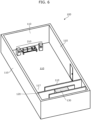
- audio device 100 may be a listening room in which stereo system 210 that includes a loudspeaker system is disposed.
- stereo system 210 that includes a loudspeaker system is disposed.
- the building material that the walls, floor, and ceiling, and the like, is composed of functions as reflective components 110.
- acoustic channel 120 is not particularly limited, and it may be of any shape, such as a cylindrical shape or a rectangular-tube shape.
- the shape of sound path 121 formed by acoustic channel 120 may be straight, curved, or bent.
- acoustic channel 120 is rectangular-tube shaped, and sound path 121 formed by acoustic channel 120 is bent in a U-shaped manner.
- the material forming acoustic channel 120 is not particularly limited and may be a material that is different from reflective components 110.
- acoustic channel 120 is formed by the extended portions of front panel 113, rear panel 114, and both side panels 115, as well as acoustic channel board 122, partition panel 123, and bottom panel 112, which is used for both the reflective space and the acoustic channel.
- the length of sound path 121 formed by acoustic channel 120 is determined based on the length of distance from the reflective component 110 disposed opposite communication hole 117 to communication hole 117.
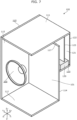
- acoustic channel 120 which forms sound path 121 having a length that corresponds to the standing wave that occurs based on the distance between top panel 111 and bottom panel 112, may be connected to communication hole 117 provided in rear panel 114, as shown in FIG. 7 .
- a bent sound path 121 was described in the above-mentioned embodiment, a straight-tube shaped sound path 121, as illustrated in FIG. 8 , may be provided. Furthermore, acoustic channel 120, which forms sound path 121, may be provided by using partition panel 123 inside a cabinet formed by reflective components 110.
- acoustic channel 120 may be connected by providing communication hole 117 in at least one of side panel 115 or top panel 111.
- each of a plurality of acoustic channels 120 that form sound paths 121 of different lengths may be connected to a plurality of communication holes 117 provided in reflective components 110.
- a bass reflex port different from communication hole 117 may be provided in reflective component 110, and holes that are in communication with reflective space 101 other than communication hole 117 may be provided.
- the present invention can be used in a cabinet in a loudspeaker system, a housing of a household appliance, such as a television, in which a loudspeaker unit is mounted, as well as a listening room and music practice studio, and the like.
Landscapes
- Physics & Mathematics (AREA)
- Engineering & Computer Science (AREA)
- Acoustics & Sound (AREA)
- Health & Medical Sciences (AREA)
- Otolaryngology (AREA)
- Signal Processing (AREA)
- Multimedia (AREA)
- Obtaining Desirable Characteristics In Audible-Bandwidth Transducers (AREA)
- Details Of Audible-Bandwidth Transducers (AREA)
Abstract
Description
- The present invention relates to an audio device that suppresses distortion in sound pressure frequency response caused by standing waves occurring within a space.
- It is known that the internal shape of a loudspeaker cabinet or the internal shape of a listening room can cause distortion in the sound pressure frequency response of sound emitted from a loudspeaker unit. To correct such distortion in sound pressure frequency response, Patent Literature (PTL) 1 describes a technique in which an acoustic channel that communicates with a reflective space is provided in a loudspeaker cabinet in order to suppress the effects of standing waves occurring in the reflective space.
- [PTL 1]
WO 2012/073431 - However, although the technique described in PTL 1 can suppress peaks in sound pressure at resonant frequencies through resonance occurring between the acoustic channel and the reflective space of the cabinet, the technique does not directly suppress dips in sound pressure frequency response.
- The present invention has been conceived in view of the above-mentioned problem and has an object to provide an audio device capable of achieving a sound pressure frequency response that has few dips and is as flat as possible.
- In order to achieve the above-mentioned object, an audio device according to one aspect of the present invention is an audio device including a plurality of reflective components that reflect sound emitted from a loudspeaker unit, the audio device forming a reflective space surrounded by the plurality of reflective components, the audio device including: an acoustic channel that is tube-shaped and includes an opening on one end and a terminating portion on an other end, the one end being connected to a communication hole provided in a reflective component among the plurality of reflective components; and a sound absorbing material disposed at a central portion of a sound path formed by the acoustic channel.
- According to the present invention, the sound absorbing material provided in the central portion of the acoustic channel can effectively suppress the amplitude of standing waves occurring within a reflective space, and thereby make it possible to flatten sound pressure frequency response.
-
- [
FIG. 1 ]
FIG. 1 is a perspective view of the external appearance of an audio device according to an embodiment. - [
FIG. 2 ]
FIG. 2 is a perspective view illustrating the audio device according to the embodiment with a portion of the reflective components omitted. - [
FIG. 3 ]
FIG. 3 shows graphs illustrating sound pressure frequency response depending on the presence or lack of an acoustic channel and/or a sound absorbing material. - [
FIG. 4 ]
FIG. 4 shows graphs illustrating sound pressure frequency response for communication holes with different aperture areas. - [
FIG. 5 ]
FIG. 5 shows graphs illustrating sound pressure frequency response for sound paths with different lengths. - [
FIG. 6 ]
FIG. 6 is a perspective view illustrating Example 1 of the audio device with a portion of the reflective components omitted. - [
FIG. 7 ]
FIG. 7 is a perspective view illustrating Example 2 of the audio device with a portion of the reflective components omitted. - [
FIG. 8 ]
FIG. 8 is a perspective view illustrating Example 3 of the audio device with a portion of the reflective components omitted. - Hereinafter, an audio device according to the present invention will be described with reference to the drawings. It should be noted that the following embodiment is merely an example for describing the present invention, and is not intended to limit the scope of the present invention. For example, the shapes, structures, materials, elements, relative positional relationships, connection states, numerical values, formulas, and details of each of the steps and the order of the steps of the methods, and the like, described in the following embodiment are mere examples, and may include details that are not included in the following descriptions. Furthermore, although geometric expressions, such as "parallel" and "orthogonal", may be used, these expressions are not mathematically precise indications and include substantially permissible error, deviation, and the like. Moreover, expressions, such as "simultaneous" and "identical (or the same)", are considered to cover a substantially permissible range of meaning.
- Additionally, the drawings are schematic illustrations, which may include emphasis, omission, or adjustment of proportion as necessary for the purpose of illustrating the present invention, and thus the shapes, positional relationships, and proportions shown may be different from actuality.
- Furthermore, hereinafter, multiple inventions may be comprehensively described as a single embodiment. Moreover, part of the contents in the description below describes optional elements related to the present invention.
-
FIG. 1 is a perspective view of the external appearance of an audio device according to an embodiment.FIG. 2 is a perspective view with a portion of the reflective components omitted illustrating the audio device according to the embodiment. -
Audio device 100 according to the embodiment is a loudspeaker cabinet in a so-called loudspeaker system, andloudspeaker unit 200 is mounted to the device.Audio device 100 includesreflective components 110,acoustic channel 120, andsound absorbing material 130. -
Loudspeaker unit 200 is an electroacoustic conversion device that converts electrical signals, such as audio signals, into the vibrations of a diaphragm. The size, shape, and structure of the diaphragm, magnetic circuit, and frame, and the like, whichloudspeaker unit 200 is composed of are not particularly limited. In the present embodiment, an electrodynamic loudspeaker that includes a cone-shaped diaphragm is used forloudspeaker unit 200. -
Reflective components 110 are components that reflect sound that is output fromloudspeaker unit 200. The space surrounded byreflective components 110 is a reflective space in which the sound that is output byloudspeaker unit 200 is reflected. In the present embodiment,reflective components 110 are a plurality of board-shapedreflective components 110 that includetop panel 111,bottom panel 112,front panel 113,rear panel 114, and twoside panels 115, which are assembled in a rectangular-cuboid shape to form a rectangular cuboid-shapedreflective space 101.Mounting hole 116 is provided penetrating throughfront panel 113 that is one ofreflective components 110, andloudspeaker unit 200 is mounted by being inserted intomounting hole 116.Communication hole 117 is provided penetrating throughbottom panel 112 that is one ofreflective components 110, thereby bringingreflective space 101 andsound path 121 into communication with each other. Specifically,bottom panel 112 is shorter thantop panel 111 in the depth-wise direction (X-axis direction in the figure), and the space surrounded bybottom panel 112,rear panel 114, and bothside panels 115 definescommunication hole 117. - There are no particular limitations on the material of
reflective components 110, and examples include wood, resin, building materials, and ceramics, and the like, and multiple materials may be combined. -
Acoustic channel 120 is a tube-shaped portion that includes opening 127 on one end and terminatingportion 129 on the other end, andacoustic channel 120 is a portion that formssound path 121 that communicates withreflective space 101 formed byreflective components 110. The length ofsound path 121 formed byacoustic channel 120 is not particularly limited and may be determined by the position of a dip occurring in sound pressure frequency response, or the like, due to distortion caused by the effects ofreflective space 101 formed byreflective components 110, for example. For example, when a dip occurs in sound pressure frequency response due to a standing wave resulting as a product of the length of distance from thereflective component 110 disposedopposite communication hole 117 tocommunication hole 117, which in the present embodiment is the length of distance fromtop panel 111 tobottom panel 112,acoustic channel 120 is set that formssound path 121 having a length that is at least 50% of the length of distance from thereflective component 110 disposedopposite communication hole 117 tocommunication hole 117. In the present embodiment, the length ofsound path 121 is set to be the same as the length of distance fromtop panel 111 tobottom panel 112. -
Sound absorbing material 130 is a component disposed atcentral portion 128 ofsound path 121 formed byacoustic channel 120. There are no particular limitations onsound absorbing material 130 as long as the material can suppress vibrations in the air, and examples include an open-cell, sponge-likesound absorbing material 130, as well as a wool-typesound absorbing material 130 that is an aggregate of fiberglass and mineral wool, and the like. The position ofsound absorbing material 130 is not particularly limited as long as it is at a central portion ofsound path 121. For example,sound absorbing material 130 may be disposed so as to obstructacoustic channel 120, orsound absorbing material 130 may be attached to the inner surface ofacoustic channel 120 so as not to obstructacoustic channel 120. It should be noted that when sound absorbingmaterial 130 is disposed in the vicinity of opening 127 ofacoustic channel 120, the remedial effect on dips in sound pressure frequency response is poor. Furthermore, when sound absorbingmaterial 130 is disposed in the vicinity of terminatingportion 129 ofacoustic channel 120, the remedial effect on dips in sound pressure frequency response is poor, and such placement is considered undesirable as it may cause new dips to occur. - In other words, the placement position of
sound absorbing material 130 inside ofacoustic channel 120 can be said to constitute a region that includes a portion withinacoustic channel 120 that has high particle velocity. Specifically,acoustic channel 120 forms asound path 121 of a length equivalent to or close to half a wavelength of the standing wave occurring withinreflective space 101 that causes the dip to occur. In this manner, a standing wave that vibrates in unison in the same frequency as the standing wave inreflective space 101 can be generated withinacoustic channel 120. Whensound absorbing material 130 is disposed at a central portion ofsound path 121, vibrations can be suppressed at the portion inacoustic channel 120 at which the particle velocity of standing waves is highest, and thus standing waves can effectively be suppressed. Consequently, the dip to be suppressed can selectively be suppressed without affecting sound pressure frequency response for other frequencies particularly the lower frequencies. - Examples of the operation of
audio device 100 having a configuration as shown above will be described using the sound pressure frequency responses graphs illustrated inFIG. 3. (a) inFIG. 3 illustrates the sound pressure frequency response of anaudio device 100 in whichacoustic channel 120 is not provided, and in whichcommunication hole 117 is not provided inreflective component 110. (b) inFIG. 3 illustrates the sound pressure frequency response of anaudio device 100 in whichacoustic channel 120 is connected tocommunication hole 117 ofreflective component 110, and in whichsound absorbing material 130 is not provided. (c) inFIG. 3 illustrates the sound pressure frequency response ofaudio device 100 according to the present embodiment. - As illustrated in (a) in
FIG. 3 , in the sound pressure frequency response of a conventional, enclosed audio device in whichacoustic channel 120 is not provided,sound pressure dip 301 occurs in the vicinity of 350 Hz. This is thought to be caused by a 350 Hz standing wave occurring inreflective space 101. - Next, as illustrated in (b) in
FIG. 3 , in the sound pressure frequency response in the case whereacoustic channel 120 is attached tocommunication hole 117 ofreflective component 110, andsound absorbing material 130 is not provided, dips other thandip 301 also occur becauseacoustic channel 120 is connected to a rectangular cuboid-shapedreflective space 101. Sound pressure frequency response becomes more distorted than whenacoustic channel 120 is not provided. - In the present embodiment illustrated in (c) in
FIG. 3 , dip 301 that occurs whenacoustic channel 120 is not provided ((a) inFIG. 3 ) is significantly remedied, and sound pressure frequency response is smooth. Furthermore, the peak occurring in the higher frequency-side vicinity ofdip 301 is also suppressed. Moreover, dips other thandip 301 that occur due to the presence ofacoustic channel 120 are eliminated, and practically no effects can be observed in sound pressure frequency response on the lower frequency-side relative to dip 301. - Next, the effects of the aperture area of
communication hole 117 on sound pressure frequency response will be described. It is preferable that the aperture area ofcommunication hole 117 is within a range of from 5% to 50% of the surface area of thereflective component 110 on whichcommunication hole 117 is provided (specifically, the surface area of suchreflective component 110 whencommunication hole 117 is not provided) (seeFIG. 4 ). The graph illustrated in (a) inFIG. 4 shows the sound pressure frequency response when the aperture area ofcommunication hole 117 is less than 5% (specifically, 1%). This illustrates that it is difficult to suppressdip 301 with acommunication hole 117 having such an aperture area. The graph illustrated in (b) inFIG. 4 shows the sound pressure frequency response when the aperture area ofcommunication hole 117 is 5%. Acommunication hole 117 with such an aperture area can suppressdip 301 in the sound pressure frequency response. The graph illustrated in (c) inFIG. 4 shows the sound pressure frequency response when the aperture area ofcommunication hole 117 is 10%. Acommunication hole 117 having such an aperture area can further suppressdip 301 in the sound pressure frequency response. The graph illustrated in (d) inFIG. 4 shows the sound pressure frequency response when the aperture area ofcommunication hole 117 is 50%. For acommunication hole 117 having such an aperture area, the vicinity ofdip 301, which is the target to be suppressed, can be rendered virtually flat. It should be noted that an aperture area ofcommunication hole 117 larger than 50% would not be practical since the volume of the box that includesacoustic channel 120 would become large. - Next, the effects of the length of
sound path 121, which is formed byacoustic channel 120, on sound pressure frequency response will be described.FIG. 5 shows graphs illustrating sound pressure frequency response for sound paths with different lengths. When the length ofsound path 121 is less than 50% of half a wavelength (for example, 25% of half a wavelength in (a) inFIG. 5 ) that corresponds to dip 301 that is the target to be suppressed in the sound pressure frequency response, practically no remedial effect is seen fordip 301. As illustrated in (b) inFIG. 5 , when the length is 50% of half a wavelength, dip 301 that is the target to be suppressed becomes shallower, and thus a remedial effect can be observed. When the length is equal to half a wavelength ((c) inFIG. 5 ), as in the present embodiment,dip 301 becomes shallow. On the other hand, even when the length ofsound path 121 is set longer than half a wavelength (for example, 125% of half a wavelength in (d) inFIG. 5 ), there is no change in the shallowness ofdip 301 compared to when the length is equal to half a wavelength. That is to say, it is preferable that the length ofsound path 121 is set to at least 50% of half a wavelength that corresponds to dip 301 that is the target to be suppressed. It should be noted that the specific length is set based on distortion of the sound pressure frequency response in other frequency ranges. - As described above, according to the present embodiment, by placing
acoustic channel 120, which formssound path 121 in whichsound absorbing material 130 is disposed atcentral portion 128, atcommunication hole 117 provided inreflective component 110, it is possible to suppress standing waves, which occur due to the relationship between the distance separatingreflective components 110 located opposite each other inreflective space 101 and the wavelength of sound emitted byloudspeaker unit 200. Furthermore, for low-frequency ranges lower than the frequency of the standing wave, the volume ofacoustic channel 120, in whichsound absorbing material 130 is disposed at a central portion ofsound path 121, is added to the volume ofreflective space 101, and thus the effects on sound pressure levels for low-frequency ranges can be suppressed. - It should be noted that the scope of the present invention is not limited to the above embodiment. For example, other embodiments realized by arbitrarily combining elements recited in the present Description or by omitting one or more of the elements may be included as an embodiment of the present invention. Moreover, variations resulting from various modifications to the above embodiment that can be conceived by those skilled in the art, so long as they do not depart from the essence of the present invention, that is, the intended meaning of the language of the appended Claims, are included within the scope of the present invention.
- Although a loudspeaker cabinet in a loudspeaker system was provided as an example of
audio device 100 in the embodiment above,audio device 100 is not limited to a cabinet. For example, as illustrated inFIG. 6 ,audio device 100 may be a listening room in whichstereo system 210 that includes a loudspeaker system is disposed. In this case, the building material that the walls, floor, and ceiling, and the like, is composed of functions asreflective components 110. - Furthermore, the shape of
acoustic channel 120 is not particularly limited, and it may be of any shape, such as a cylindrical shape or a rectangular-tube shape. Furthermore, the shape ofsound path 121 formed byacoustic channel 120 may be straight, curved, or bent. In the present embodiment,acoustic channel 120 is rectangular-tube shaped, andsound path 121 formed byacoustic channel 120 is bent in a U-shaped manner. The material formingacoustic channel 120 is not particularly limited and may be a material that is different fromreflective components 110. In the present embodiment,acoustic channel 120 is formed by the extended portions offront panel 113,rear panel 114, and bothside panels 115, as well asacoustic channel board 122,partition panel 123, andbottom panel 112, which is used for both the reflective space and the acoustic channel. - Furthermore, in the above-mentioned embodiment, the length of
sound path 121 formed byacoustic channel 120 is determined based on the length of distance from thereflective component 110 disposedopposite communication hole 117 tocommunication hole 117. However,acoustic channel 120, which formssound path 121 having a length that corresponds to the standing wave that occurs based on the distance betweentop panel 111 andbottom panel 112, may be connected tocommunication hole 117 provided inrear panel 114, as shown inFIG. 7 . - Moreover, although a
bent sound path 121 was described in the above-mentioned embodiment, a straight-tube shapedsound path 121, as illustrated inFIG. 8 , may be provided. Furthermore,acoustic channel 120, which formssound path 121, may be provided by usingpartition panel 123 inside a cabinet formed byreflective components 110. - Additionally,
acoustic channel 120 may be connected by providingcommunication hole 117 in at least one ofside panel 115 ortop panel 111. - Furthermore, each of a plurality of
acoustic channels 120 that formsound paths 121 of different lengths may be connected to a plurality of communication holes 117 provided inreflective components 110. - Moreover, a bass reflex port different from
communication hole 117 may be provided inreflective component 110, and holes that are in communication withreflective space 101 other thancommunication hole 117 may be provided. - The present invention can be used in a cabinet in a loudspeaker system, a housing of a household appliance, such as a television, in which a loudspeaker unit is mounted, as well as a listening room and music practice studio, and the like.
-
- 100
- audio device
- 101
- reflective space
- 110
- reflective component
- 111
- top panel
- 112
- bottom panel
- 113
- front panel
- 114
- rear panel
- 115
- side panel
- 116
- mounting hole
- 117
- communication hole
- 120
- acoustic channel
- 121
- sound path
- 122
- acoustic channel board
- 123
- partition panel
- 127
- opening
- 128
- central portion
- 129
- terminating portion
- 130
- sound absorbing material
- 200
- loudspeaker unit
- 210
- stereo system
- 301
- dip
Claims (4)
- An audio device including a plurality of reflective components that reflect sound emitted from a loudspeaker unit, the audio device forming a reflective space surrounded by the plurality of reflective components, the audio device comprising:an acoustic channel that is tube-shaped and includes an opening on one end and a terminating portion on an other end, the one end being connected to a communication hole provided in a reflective component among the plurality of reflective components; anda sound absorbing material disposed at a central portion of a sound path formed by the acoustic channel.
- The audio device according to claim 1, wherein
a length of the sound path formed by the acoustic channel is at least 50 percent of a length of distance between any pair of mutually opposed reflective components among the plurality of reflective components. - The audio device according to claim 1 or 2, wherein
an aperture area of the communication hole is a surface area that is within a range of from 5 percent to less than 50 percent of a surface area of the reflective component in which the communication hole is provided. - The audio device according to any one of claims 1 to 3, further comprising:
the loudspeaker unit that is mounted by being inserted in a mounting hole provided penetrating through a reflective component among the plurality of reflective components.
Applications Claiming Priority (2)
| Application Number | Priority Date | Filing Date | Title |
|---|---|---|---|
| JP2020189616 | 2020-11-13 | ||
| PCT/JP2021/038691 WO2022102360A1 (en) | 2020-11-13 | 2021-10-20 | Audio device |
Publications (2)
| Publication Number | Publication Date |
|---|---|
| EP4246999A1 true EP4246999A1 (en) | 2023-09-20 |
| EP4246999A4 EP4246999A4 (en) | 2024-04-03 |
Family
ID=81602230
Family Applications (1)
| Application Number | Title | Priority Date | Filing Date |
|---|---|---|---|
| EP21891607.0A Pending EP4246999A4 (en) | 2020-11-13 | 2021-10-20 | AUDIO DEVICE |
Country Status (5)
| Country | Link |
|---|---|
| US (1) | US12513455B2 (en) |
| EP (1) | EP4246999A4 (en) |
| JP (1) | JP7699607B2 (en) |
| CN (1) | CN116491128A (en) |
| WO (1) | WO2022102360A1 (en) |
Families Citing this family (4)
| Publication number | Priority date | Publication date | Assignee | Title |
|---|---|---|---|---|
| CN116472719B (en) * | 2020-11-18 | 2026-04-07 | 舒尔·阿奎西什控股公司 | Audio device with low-frequency spread filter |
| USD1027918S1 (en) * | 2022-08-29 | 2024-05-21 | Ningbo Yinzhou Luxsound Electronics Co., Ltd. | Microphone isolation shield |
| JP1751129S (en) * | 2023-03-09 | 2023-08-18 | speaker | |
| CN118764754A (en) * | 2024-07-19 | 2024-10-11 | 华勤技术股份有限公司 | Speakers |
Family Cites Families (34)
| Publication number | Priority date | Publication date | Assignee | Title |
|---|---|---|---|---|
| US2866514A (en) * | 1955-04-27 | 1958-12-30 | Weathers Paul | Corrective loud speaker enclosure |
| GB921213A (en) | 1958-04-03 | 1963-03-13 | John Somerset Murray | Improvements in and relating to loudspeaker enclosures |
| JPS5435704Y2 (en) * | 1976-01-19 | 1979-10-30 | ||
| US4224469A (en) * | 1979-01-02 | 1980-09-23 | Karson Theodore R | Stereo speaker system |
| US4930596A (en) * | 1987-06-16 | 1990-06-05 | Matsushita Electric Industrial Co., Ltd. | Loudspeaker system |
| US4837837A (en) * | 1987-11-05 | 1989-06-06 | Taddeo Anthony R | Loudspeaker |
| JPH04110087U (en) * | 1991-03-08 | 1992-09-24 | 三菱電機株式会社 | bass reflex speaker |
| JPH0549081A (en) * | 1991-08-09 | 1993-02-26 | Pioneer Electron Corp | Speaker system |
| US5373564A (en) * | 1992-10-02 | 1994-12-13 | Spear; Robert J. | Transmission line for planar waves |
| US6002781A (en) * | 1993-02-24 | 1999-12-14 | Matsushita Electric Industrial Co., Ltd. | Speaker system |
| US6278789B1 (en) * | 1993-05-06 | 2001-08-21 | Bose Corporation | Frequency selective acoustic waveguide damping |
| JP2769448B2 (en) * | 1995-06-19 | 1998-06-25 | 政一郎 澤田 | Standing wave or specific wave reduction device |
| JPH1013982A (en) * | 1996-06-26 | 1998-01-16 | Matsushita Electric Ind Co Ltd | Speaker device |
| KR100248107B1 (en) * | 1997-01-30 | 2000-03-15 | 김석주 | Bass Transmission Speaker Enclosure |
| JPH11220789A (en) * | 1998-01-30 | 1999-08-10 | Sony Corp | Electroacoustic transducer |
| US6771787B1 (en) * | 1998-09-03 | 2004-08-03 | Bose Corporation | Waveguide electroacoustical transducing |
| JP3763682B2 (en) * | 1998-10-14 | 2006-04-05 | パイオニア株式会社 | Speaker device |
| US6700984B1 (en) * | 1999-12-07 | 2004-03-02 | California Institute Of Technology | Non-linearly tapering transmission line speakers |
| US6912290B1 (en) * | 2000-11-16 | 2005-06-28 | Alpine Electronics, Inc. | Speaker unit for low frequency reproduction |
| US7269270B2 (en) * | 2002-10-17 | 2007-09-11 | Bose Corporation | Standing wave reducing |
| US7614479B2 (en) * | 2004-05-12 | 2009-11-10 | Jan Plummer | Sound enhancement module |
| JP2006211195A (en) | 2005-01-27 | 2006-08-10 | Matsushita Electric Ind Co Ltd | Speaker device |
| US7748495B2 (en) * | 2005-04-20 | 2010-07-06 | Krueger Paul M | Tubular loudspeaker |
| JP2008211389A (en) | 2007-02-23 | 2008-09-11 | Matsushita Electric Works Ltd | Intercom device |
| JP2009118182A (en) | 2007-11-06 | 2009-05-28 | Sharp Corp | Speaker device |
| EP2648421B1 (en) * | 2010-12-03 | 2016-10-05 | Panasonic Intellectual Property Management Co., Ltd. | Speaker system |
| JP6044164B2 (en) * | 2011-09-09 | 2016-12-14 | ヤマハ株式会社 | Sound equipment |
| JP6465096B2 (en) | 2011-09-09 | 2019-02-06 | ヤマハ株式会社 | Sound equipment |
| JP2013062630A (en) * | 2011-09-13 | 2013-04-04 | Masaki Chigira | Double cylindrical loudspeaker with internal sound absorbing pipe |
| JP5817762B2 (en) | 2013-03-07 | 2015-11-18 | ヤマハ株式会社 | Sound equipment |
| JP6251881B2 (en) * | 2013-07-24 | 2017-12-27 | パナソニックIpマネジメント株式会社 | SPEAKER SYSTEM, ELECTRONIC DEVICE USING THE SAME, AND MOBILE DEVICE |
| JP6593741B2 (en) * | 2014-04-30 | 2019-10-23 | パナソニックIpマネジメント株式会社 | Speaker system |
| CN107205194B (en) * | 2017-06-07 | 2020-03-06 | 鞠波 | Sound box and sound box system |
| JP7213065B2 (en) * | 2018-02-07 | 2023-01-26 | パナソニック インテレクチュアル プロパティ コーポレーション オブ アメリカ | speaker system |
-
2021
- 2021-10-20 CN CN202180073171.5A patent/CN116491128A/en active Pending
- 2021-10-20 JP JP2022561363A patent/JP7699607B2/en active Active
- 2021-10-20 EP EP21891607.0A patent/EP4246999A4/en active Pending
- 2021-10-20 WO PCT/JP2021/038691 patent/WO2022102360A1/en not_active Ceased
-
2023
- 2023-04-26 US US18/139,599 patent/US12513455B2/en active Active
Also Published As
| Publication number | Publication date |
|---|---|
| JP7699607B2 (en) | 2025-06-27 |
| EP4246999A4 (en) | 2024-04-03 |
| WO2022102360A1 (en) | 2022-05-19 |
| US12513455B2 (en) | 2025-12-30 |
| CN116491128A (en) | 2023-07-25 |
| US20230269527A1 (en) | 2023-08-24 |
| JPWO2022102360A1 (en) | 2022-05-19 |
Similar Documents
| Publication | Publication Date | Title |
|---|---|---|
| US12513455B2 (en) | Audio device | |
| EP3133832A1 (en) | Thin high performance constant directivity waveguide and speaker | |
| EP1401237B1 (en) | Asymmetrical loudspeaker enclosures with enhanced low frequency response | |
| US20130043089A1 (en) | Speaker enclosure | |
| US20050087392A1 (en) | Loudspeaker enclosure | |
| US5844176A (en) | Speaker enclosure having parallel porting channels for mid-range and bass speakers | |
| US10231049B2 (en) | Loudspeaker, loudspeaker driver and loudspeaker design process | |
| JP7455196B2 (en) | Electronics | |
| US5975236A (en) | Speaker assembly | |
| US9113244B2 (en) | Loudspeaker for eliminating a frequency response dip | |
| CN217486606U (en) | Loudspeaker module and sound box with screen | |
| CN107205194B (en) | Sound box and sound box system | |
| WO2002003751A1 (en) | Speaker system, and noise canceling device | |
| US6721431B1 (en) | Prismatic loudspeaker/microphone array | |
| US12309546B2 (en) | Directivity pattern control waveguide for a speaker, and speaker including a directivity pattern control waveguide | |
| KR20110031570A (en) | speaker | |
| CN207926915U (en) | A kind of loud speaker bugle | |
| JP4838846B2 (en) | Audio output device and acoustic device accommodation device | |
| JP2003319481A (en) | Speaker enclosure | |
| CN218041681U (en) | Sound effect enhancing device and sound box | |
| US20250274715A1 (en) | Speaker apparatus | |
| EP2129164A1 (en) | Dipole loudspeaker with acoustic waveguide | |
| CN117041809A (en) | Electronic equipment | |
| WO2012009861A1 (en) | Bass bandpass loudspeaker system | |
| EP2187655A1 (en) | A loudspeaker system comprising an acoustic filter |
Legal Events
| Date | Code | Title | Description |
|---|---|---|---|
| STAA | Information on the status of an ep patent application or granted ep patent |
Free format text: STATUS: THE INTERNATIONAL PUBLICATION HAS BEEN MADE |
|
| PUAI | Public reference made under article 153(3) epc to a published international application that has entered the european phase |
Free format text: ORIGINAL CODE: 0009012 |
|
| STAA | Information on the status of an ep patent application or granted ep patent |
Free format text: STATUS: REQUEST FOR EXAMINATION WAS MADE |
|
| 17P | Request for examination filed |
Effective date: 20230424 |
|
| AK | Designated contracting states |
Kind code of ref document: A1 Designated state(s): AL AT BE BG CH CY CZ DE DK EE ES FI FR GB GR HR HU IE IS IT LI LT LU LV MC MK MT NL NO PL PT RO RS SE SI SK SM TR |
|
| DAV | Request for validation of the european patent (deleted) | ||
| DAX | Request for extension of the european patent (deleted) | ||
| A4 | Supplementary search report drawn up and despatched |
Effective date: 20240305 |
|
| RIC1 | Information provided on ipc code assigned before grant |
Ipc: G10K 11/16 20060101ALI20240228BHEP Ipc: H04R 1/28 20060101ALI20240228BHEP Ipc: H04R 1/02 20060101AFI20240228BHEP |
|
| STAA | Information on the status of an ep patent application or granted ep patent |
Free format text: STATUS: EXAMINATION IS IN PROGRESS |
|
| 17Q | First examination report despatched |
Effective date: 20260309 |