EP4246802A1 - Fotovoltaisches system und zirkulationsunterdrückungsverfahren - Google Patents
Fotovoltaisches system und zirkulationsunterdrückungsverfahren Download PDFInfo
- Publication number
- EP4246802A1 EP4246802A1 EP20965321.1A EP20965321A EP4246802A1 EP 4246802 A1 EP4246802 A1 EP 4246802A1 EP 20965321 A EP20965321 A EP 20965321A EP 4246802 A1 EP4246802 A1 EP 4246802A1
- Authority
- EP
- European Patent Office
- Prior art keywords
- inverter
- direct current
- common
- inverters
- bus voltage
- Prior art date
- Legal status (The legal status is an assumption and is not a legal conclusion. Google has not performed a legal analysis and makes no representation as to the accuracy of the status listed.)
- Granted
Links
Images


Classifications
-
- H—ELECTRICITY
- H02—GENERATION; CONVERSION OR DISTRIBUTION OF ELECTRIC POWER
- H02M—APPARATUS FOR CONVERSION BETWEEN AC AND AC, BETWEEN AC AND DC, OR BETWEEN DC AND DC, AND FOR USE WITH MAINS OR SIMILAR POWER SUPPLY SYSTEMS; CONVERSION OF DC OR AC INPUT POWER INTO SURGE OUTPUT POWER; CONTROL OR REGULATION THEREOF
- H02M1/00—Details of apparatus for conversion
- H02M1/32—Means for protecting converters other than automatic disconnection
-
- H—ELECTRICITY
- H02—GENERATION; CONVERSION OR DISTRIBUTION OF ELECTRIC POWER
- H02M—APPARATUS FOR CONVERSION BETWEEN AC AND AC, BETWEEN AC AND DC, OR BETWEEN DC AND DC, AND FOR USE WITH MAINS OR SIMILAR POWER SUPPLY SYSTEMS; CONVERSION OF DC OR AC INPUT POWER INTO SURGE OUTPUT POWER; CONTROL OR REGULATION THEREOF
- H02M1/00—Details of apparatus for conversion
- H02M1/12—Arrangements for reducing harmonics from AC input or output
- H02M1/123—Suppression of common mode voltage or current
-
- H—ELECTRICITY
- H02—GENERATION; CONVERSION OR DISTRIBUTION OF ELECTRIC POWER
- H02M—APPARATUS FOR CONVERSION BETWEEN AC AND AC, BETWEEN AC AND DC, OR BETWEEN DC AND DC, AND FOR USE WITH MAINS OR SIMILAR POWER SUPPLY SYSTEMS; CONVERSION OF DC OR AC INPUT POWER INTO SURGE OUTPUT POWER; CONTROL OR REGULATION THEREOF
- H02M7/00—Conversion of AC power input into DC power output; Conversion of DC power input into AC power output
- H02M7/42—Conversion of DC power input into AC power output without possibility of reversal
- H02M7/44—Conversion of DC power input into AC power output without possibility of reversal by static converters
- H02M7/48—Conversion of DC power input into AC power output without possibility of reversal by static converters using discharge tubes with control electrode or semiconductor devices with control electrode
- H02M7/493—Conversion of DC power input into AC power output without possibility of reversal by static converters using discharge tubes with control electrode or semiconductor devices with control electrode the static converters being arranged for operation in parallel
-
- H—ELECTRICITY
- H02—GENERATION; CONVERSION OR DISTRIBUTION OF ELECTRIC POWER
- H02J—ELECTRIC POWER NETWORKS; CIRCUIT ARRANGEMENTS OR SYSTEMS FOR SUPPLYING OR DISTRIBUTING ELECTRIC POWER; SYSTEMS FOR STORING ELECTRIC ENERGY
- H02J2101/00—Supply or distribution of decentralised, dispersed or local electric power generation
- H02J2101/20—Dispersed power generation using renewable energy sources
- H02J2101/22—Solar energy
- H02J2101/24—Photovoltaics
-
- H—ELECTRICITY
- H02—GENERATION; CONVERSION OR DISTRIBUTION OF ELECTRIC POWER
- H02J—ELECTRIC POWER NETWORKS; CIRCUIT ARRANGEMENTS OR SYSTEMS FOR SUPPLYING OR DISTRIBUTING ELECTRIC POWER; SYSTEMS FOR STORING ELECTRIC ENERGY
- H02J3/00—Circuit arrangements for AC mains or AC distribution networks
- H02J3/38—Arrangements for feeding a single network from two or more generators or sources in parallel; Arrangements for feeding already energised networks from additional generators or sources in parallel
- H02J3/381—Dispersed generators
-
- H—ELECTRICITY
- H02—GENERATION; CONVERSION OR DISTRIBUTION OF ELECTRIC POWER
- H02M—APPARATUS FOR CONVERSION BETWEEN AC AND AC, BETWEEN AC AND DC, OR BETWEEN DC AND DC, AND FOR USE WITH MAINS OR SIMILAR POWER SUPPLY SYSTEMS; CONVERSION OF DC OR AC INPUT POWER INTO SURGE OUTPUT POWER; CONTROL OR REGULATION THEREOF
- H02M1/00—Details of apparatus for conversion
- H02M1/0067—Converter structures employing plural converter units, other than for parallel operation of the units on a single load
- H02M1/0074—Plural converter units whose inputs are connected in series
-
- H—ELECTRICITY
- H02—GENERATION; CONVERSION OR DISTRIBUTION OF ELECTRIC POWER
- H02M—APPARATUS FOR CONVERSION BETWEEN AC AND AC, BETWEEN AC AND DC, OR BETWEEN DC AND DC, AND FOR USE WITH MAINS OR SIMILAR POWER SUPPLY SYSTEMS; CONVERSION OF DC OR AC INPUT POWER INTO SURGE OUTPUT POWER; CONTROL OR REGULATION THEREOF
- H02M5/00—Conversion of AC power input into AC power output, e.g. for change of voltage, for change of frequency, for change of number of phases
- H02M5/02—Conversion of AC power input into AC power output, e.g. for change of voltage, for change of frequency, for change of number of phases without intermediate conversion into DC
- H02M5/04—Conversion of AC power input into AC power output, e.g. for change of voltage, for change of frequency, for change of number of phases without intermediate conversion into DC by static converters
- H02M5/10—Conversion of AC power input into AC power output, e.g. for change of voltage, for change of frequency, for change of number of phases without intermediate conversion into DC by static converters using transformers
- H02M5/14—Conversion of AC power input into AC power output, e.g. for change of voltage, for change of frequency, for change of number of phases without intermediate conversion into DC by static converters using transformers for conversion between circuits of different phase number
-
- Y—GENERAL TAGGING OF NEW TECHNOLOGICAL DEVELOPMENTS; GENERAL TAGGING OF CROSS-SECTIONAL TECHNOLOGIES SPANNING OVER SEVERAL SECTIONS OF THE IPC; TECHNICAL SUBJECTS COVERED BY FORMER USPC CROSS-REFERENCE ART COLLECTIONS [XRACs] AND DIGESTS
- Y02—TECHNOLOGIES OR APPLICATIONS FOR MITIGATION OR ADAPTATION AGAINST CLIMATE CHANGE
- Y02E—REDUCTION OF GREENHOUSE GAS [GHG] EMISSIONS, RELATED TO ENERGY GENERATION, TRANSMISSION OR DISTRIBUTION
- Y02E10/00—Energy generation through renewable energy sources
- Y02E10/50—Photovoltaic [PV] energy
- Y02E10/56—Power conversion systems, e.g. maximum power point trackers
Definitions
- This application relates to the field of photovoltaic power generation technologies, and in particular, to a photovoltaic system and a circulating current suppression method.
- a photovoltaic array outputs a direct current
- an inverter converts the direct current into an alternating current
- the alternating current is connected to a power grid or supplied to a load.
- a common implementation is to connect a plurality of inverters in series and parallel, to transmit a higher power.
- a circulating current is usually formed between the inverters.
- the circulating current causes the following adverse impact: On one hand, power consumption is increased, and efficiency is lowered, affecting a service life and reliability of a power device. On the other hand, a large circulating current spike may cause shutdown of the inverter due to triggering of overcurrent protection. In addition, the circulating current may cause the inverter to detect a relatively large leakage current, resulting in an action of leakage current mis-protection.
- This application provides a photovoltaic system and a circulating current suppression method, to suppress a circulating current between inverters connected in parallel, thereby reducing loss, improving efficiency, and avoiding overcurrent protection and leakage current protection caused by a circulating current.
- the photovoltaic system may be a unipolar photovoltaic system, or may be a bipolar photovoltaic system, provided that the photovoltaic system includes at least two inverters whose output terminals, namely, alternating current sides, are connected in parallel.
- the photovoltaic system includes a controller and at least two inverters.
- the controller herein is only a generic term. During specific control, a plurality of controllers may be included. To be specific, the controllers and the inverters are in a one-to-one correspondence. The controllers may be integrated with the inverters. To be specific, the controllers are located in a cabinet of the inverters.
- a plurality of inverters may share one controller, and the controller may communicate with the plurality of inverters.
- a direct current input terminal of each inverter is connected to a corresponding photovoltaic array. Whether the input terminal of the inverter is directly connected to the photovoltaic array or indirectly connected to the photovoltaic array by using a direct current-direct current converter is not limited herein. Alternating current output terminals of the at least two inverters are connected in parallel.
- the controller obtains a direct current component of a common-mode output current of at least one of the at least two inverters, to be specific, may obtain a direct current component of a common-mode output current of each inverter, or may obtain direct current components of common-mode output currents of some of the inverters, to suppress a circulating current between the at least two inverters.
- a direct current component of a common-mode output current may represent a magnitude of a circulating current between inverters
- a direct current bus voltage of a corresponding inverter is adjusted based on a magnitude of a direct current component of a common-mode output current.
- direct current bus voltages of inverters are the same, there is no circulating current between inverters whose output terminals are connected in parallel.
- a cause of a circulating current is that direct current bus voltages of inverters are different. Therefore, a direct current bus voltage of an inverter may be adjusted based on a direct current component of a common-mode output current, to suppress a circulating current between inverters whose output terminals are connected in parallel.
- the photovoltaic system is a bipolar photovoltaic system.
- the bipolar photovoltaic system includes an even quantity of inverters. Every two inverters constitute one group. Each group includes two inverters: one positive inverter and one negative inverter that constitute a bipolar inverter.
- M groups of bipolar inverters are connected in parallel, where M is an integer greater than or equal to 2.
- a specific quantity of groups is not limited in this embodiment of this application. The following describes a case in which the inverters in the bipolar photovoltaic system are not distinguished in terms of a master or a slave, and all the inverters are at a same location for circulating current suppression.
- the at least two inverters include a positive inverter group and a negative inverter group, the positive inverter group includes at least a first inverter and a third inverter, and the negative inverter group includes at least a second inverter and a fourth inverter.
- a negative direct current input terminal of the first inverter is connected to a positive direct current input terminal of the second inverter.
- a negative direct current input terminal of the third inverter is connected to a positive direct current input terminal of the fourth inverter.
- Alternating current output terminals of the first inverter and the third inverter are connected in parallel, and alternating current output terminals of the second inverter and the fourth inverter are connected in parallel.
- the controller is specifically configured to: obtain a direct current component of a common-mode output current of each of the at least two inverters; if a direct current component of a common-mode output current of an inverter in the positive inverter group is greater than a preset threshold, reduce a direct current bus voltage of the corresponding inverter, or if a direct current component of a common-mode output current of an inverter in the positive inverter group is less than the preset threshold, increase a direct current bus voltage of the corresponding inverter; and if a direct current component of a common-mode output current of an inverter in the negative inverter group is greater than a preset threshold, increase a direct current bus voltage of the corresponding inverter, or if a direct current component of a common-mode output current of an inverter in the negative inverter group is less than the preset threshold, reduce a direct current bus voltage of the corresponding inverter.
- the bipolar photovoltaic system is further described in a case in which the inverters are distinguished in terms of a master or a slave, and the master and the slave use different circulating current suppression modes.
- a direct current bus voltage of the master does not need to change with a direct current component of a common-mode output current, in other words, is controlled to be a fixed value.
- a direct current bus voltage of the slave changes with a magnitude of a common-mode output current, to suppress a circulating current between inverters.
- the at least two inverters include a positive inverter group and a negative inverter group
- the positive inverter group includes at least a first inverter and a third inverter
- the negative inverter group includes at least a second inverter and a fourth inverter
- a negative direct current input terminal of the first inverter is connected to a positive direct current input terminal of the second inverter
- a negative direct current input terminal of the third inverter is connected to a positive direct current input terminal of the fourth inverter
- alternating current output terminals of the first inverter and the third inverter are connected in parallel
- alternating current output terminals of the second inverter and the fourth inverter are connected in parallel
- one of the first inverter and the third inverter is a master, and the other is a slave
- one of the second inverter and the fourth inverter is a master, and the other is a slave.
- the controller is specifically configured to: control direct current bus voltages of all the masters to be a preset voltage; obtain a direct current component of a common-mode output current of the slave; if a direct current component of a common-mode output current of the slave in the positive inverter group is greater than a preset threshold, reduce a direct current bus voltage of the corresponding slave, or if the direct current component of the common-mode output current of the slave in the positive inverter group is less than the preset threshold, increase the direct current bus voltage of the corresponding slave; and if a direct current component of a common-mode output current of the slave in the negative inverter group is greater than a preset threshold, increase a direct current bus voltage of the corresponding slave, or if the direct current component of the common-mode output current of the slave in the negative inverter group is less than the preset threshold, reduce the direct current bus voltage of the corresponding slave.
- a direct current bus voltage of an inverter in the bipolar photovoltaic system, to control a direct current bus voltage of an inverter as little as possible, masters are set as many as possible, and slaves are set as few as possible, so that a direct current bus voltage of a master is fixed, and only a direct current bus voltage of a slave is adjusted to suppress a circulating current between inverters connected in parallel.
- the at least two inverters include a positive inverter group and a negative inverter group
- the positive inverter group includes at least a first inverter and a third inverter
- the negative inverter group includes at least a second inverter and a fourth inverter
- a negative direct current input terminal of the first inverter is connected to a positive direct current input terminal of the second inverter
- a negative direct current input terminal of the third inverter is connected to a positive direct current input terminal of the fourth inverter
- alternating current output terminals of the first inverter and the third inverter are connected in parallel
- alternating current output terminals of the second inverter and the fourth inverter are connected in parallel
- both the first inverter and the third inverter are masters, one of the second inverter and the fourth inverter is a master, and the other is a slave; or both the second inverter and the fourth inverter are masters, one of the first inverter and the third invert
- the controller is specifically configured to: control direct current bus voltages of all the masters to be a preset voltage; obtain a direct current component of a common-mode output current of the slave; and when the slave is located in the positive inverter group, if the direct current component of the common-mode output current is greater than a preset threshold, reduce a direct current bus voltage of the slave, or if the direct current component of the common-mode output current is less than the preset threshold, increase the direct current bus voltage of the slave; or when the slave is located in the negative inverter group, if the direct current component of the common-mode output current is greater than a preset threshold, increase a direct current bus voltage of the slave, or if the direct current component of the common-mode output current is less than the preset threshold, reduce the direct current bus voltage of the corresponding slave.
- the photovoltaic system described above is a bipolar photovoltaic system, and the following describes a case of a unipolar photovoltaic system, where no master or slave is distinguished, all inverters connected in parallel are equal in status, and negative direct current input terminals of at least two inverters are connected, in other words, input negative electrodes of a plurality of inverters are connected.
- the controller obtains a direct current component of a common-mode output current of each of the at least two inverters; and if the direct current component of the common-mode output current is greater than a preset threshold, reduces a direct current bus voltage of the corresponding inverter; or if the direct current component of the common-mode output current is less than the preset threshold, increases the direct current bus voltage of the corresponding inverter.
- the unipolar photovoltaic system is further described.
- Negative direct current input terminals of the at least two inverters are connected, in other words, input negative electrodes are connected, or negative electrodes are connected.
- Inverters connected in parallel are distinguished in terms of a master or a slave.
- a direct current bus voltage of the master is fixed, and only a direct current bus voltage of the slave is adjusted to suppress a circulating current between the inverters connected in parallel.
- one of the at least two inverters is a master, and other inverters are slaves; and the controller is specifically configured to: obtain a direct current component of a common-mode output current of each slave; if the direct current component of the common-mode output current is greater than a preset threshold, reduce a direct current bus voltage of the corresponding slave, or if the direct current component of the common-mode output current is less than the preset threshold, increase the direct current bus voltage of the corresponding slave; and control a direct current bus voltage of the master to be a preset voltage.
- the unipolar photovoltaic system is further described.
- Positive direct current input terminals of the at least two inverters are connected, in other words, input positive electrodes are connected, or positive electrodes are connected.
- the inverters are not distinguished in terms of a master or a slave, and are equal in status.
- the controller obtains a direct current component of a common-mode output current of each inverter; and if the direct current component of the common-mode output current is greater than a preset threshold, increases a direct current bus voltage of the corresponding inverter; or if the direct current component of the common-mode output current is less than the preset threshold, reduces the direct current bus voltage of the corresponding inverter.
- the unipolar photovoltaic system is further described.
- Positive direct current input terminals of the at least two inverters are connected, in other words, input positive electrodes are connected, or positive electrodes are connected.
- Inverters connected in parallel are distinguished in terms of a master or a slave.
- a direct current bus voltage of the master is fixed, and only a direct current bus voltage of the slave is adjusted based on a direct current component of a common-mode output current, to suppress a circulating current.
- one of the at least two inverters is a master, and other inverters are slaves; and the controller is specifically configured to: obtain a direct current component of a common-mode output current of the slave; if the direct current component of the common-mode output current is greater than a preset threshold, increase a direct current bus voltage of the slave, or if the direct current component of the common-mode output current is less than the preset threshold, reduce the direct current bus voltage of the slave; and control a direct current bus voltage of the master to be a preset voltage.
- the controller obtains an average value of three-phase output currents of the at least one inverter as the common-mode output current, and extracts the direct current component of the common-mode output current from the common-mode output current.
- the controller obtains a direct current component of each of three-phase output currents of the at least one inverter, obtains an average value of direct current components of the three-phase output currents based on the direct current component of each of the three-phase output currents, and uses the average value as the direct current component of the common-mode output current.
- the controller is specifically configured to: for an inverter with a constant input power, reduce an output power to increase a direct current bus voltage, or increase an output power to reduce a direct current bus voltage.
- the controller is specifically configured to: for an inverter with a constant output power, increase an input power to increase a direct current bus voltage, or reduce an input power to reduce a direct current bus voltage.
- the inverters and the controllers are in a one-to-one correspondence.
- the controllers may be integrated in a cabinet of the inverters, and the controllers may communicate with each other.
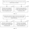
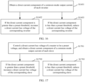
- an embodiment of this application further provides a circulating current suppression method for a photovoltaic system.
- Advantages of the foregoing system are applicable to the following method, and details are not described herein again.
- the photovoltaic system includes at least two inverters. A direct current input terminal of each inverter is connected to a corresponding photovoltaic array. Alternating current output terminals of the at least two inverters are connected in parallel.
- the method includes: obtaining a direct current component of a common-mode output current of at least one of the at least two inverters; and adjusting a direct current bus voltage of the corresponding inverter based on a magnitude of the direct current component of the common-mode output current, to suppress a circulating current between the at least two inverters.
- the at least two inverters include a positive inverter group and a negative inverter group
- the positive inverter group includes at least a first inverter and a third inverter
- the negative inverter group includes at least a second inverter and a fourth inverter.
- a negative direct current input terminal of the first inverter is connected to a positive direct current input terminal of the second inverter.
- a negative direct current input terminal of the third inverter is connected to a positive direct current input terminal of the fourth inverter.
- Alternating current output terminals of the first inverter and the third inverter are connected in parallel, and alternating current output terminals of the second inverter and the fourth inverter are connected in parallel.
- the obtaining a direct current component of a common-mode output current of at least one of the at least two inverters, and adjusting a direct current bus voltage of the corresponding inverter based on a magnitude of the direct current component specifically includes: obtaining a direct current component of a common-mode output current of each of the at least two inverters; if a direct current component of a common-mode output current of an inverter in the positive inverter group is greater than a preset threshold, reducing a direct current bus voltage of the corresponding inverter, or if a direct current component of a common-mode output current of an inverter in the positive inverter group is less than the preset threshold, increasing a direct current bus voltage of the corresponding inverter; and if a direct current component of a common-mode output current of an inverter in the negative inverter group is greater than a preset threshold, increasing a direct current bus voltage of the corresponding inverter, or if a direct current component of a common-mode
- the at least two inverters include a positive inverter group and a negative inverter group
- the positive inverter group includes at least a first inverter and a third inverter
- the negative inverter group includes at least a second inverter and a fourth inverter
- a negative direct current input terminal of the first inverter is connected to a positive direct current input terminal of the second inverter
- a negative direct current input terminal of the third inverter is connected to a positive direct current input terminal of the fourth inverter
- alternating current output terminals of the first inverter and the third inverter are connected in parallel
- alternating current output terminals of the second inverter and the fourth inverter are connected in parallel
- one of the first inverter and the second inverter is a master, and the other is a slave
- one of the third inverter and the fourth inverter is a master, and the other is a slave.
- the obtaining a direct current component of a common-mode output current of at least one of the at least two inverters, and adjusting a direct current bus voltage of the corresponding inverter based on a magnitude of the direct current component specifically includes: controlling direct current bus voltages of all the masters to be a preset voltage; obtaining a direct current component of a common-mode output current of the slave; if a direct current component of a common-mode output current of the slave in the positive inverter group is greater than a preset threshold, reducing a direct current bus voltage of the corresponding slave, or if the direct current component of the common-mode output current of the slave in the positive inverter group is less than the preset threshold, increasing the direct current bus voltage of the corresponding slave; and if a direct current component of a common-mode output current of the slave in the negative inverter group is greater than a preset threshold, increasing a direct current bus voltage of the corresponding slave, or if the direct current component of the common-mode output current of the slave
- negative direct current input terminals of the at least two inverters are connected; and the obtaining a direct current component of a common-mode output current of at least one of the at least two inverters, and adjusting a direct current bus voltage of the corresponding inverter based on a magnitude of the direct current component of the common-mode output current specifically includes: obtaining a direct current component of a common-mode output current of each of the at least two inverters; and if the direct current component of the common-mode output current is greater than a preset threshold, reducing a direct current bus voltage of the corresponding inverter; or if the direct current component of the common-mode output current is less than the preset threshold, increasing the direct current bus voltage of the corresponding inverter.
- negative direct current input terminals of the at least two inverters are connected, one of the at least two inverters is a master, and other inverters are slaves; and the obtaining a direct current component of a common-mode output current of at least one of the at least two inverters, and adjusting a direct current bus voltage of the corresponding inverter based on a magnitude of the direct current component of the common-mode output current specifically includes: obtaining a direct current component of a common-mode output current of each slave; if the direct current component of the common-mode output current is greater than a preset threshold, reducing a direct current bus voltage of the corresponding slave, or if the direct current component of the common-mode output current is less than the preset threshold, increasing the direct current bus voltage of the corresponding slave; and controlling a direct current bus voltage of the master to be a preset voltage.
- positive direct current input terminals of the at least two inverters are connected; and the obtaining a direct current component of a common-mode output current of at least one of the at least two inverters, and adjusting a direct current bus voltage of the corresponding inverter based on a magnitude of the direct current component of the common-mode output current specifically includes: obtaining a direct current component of a common-mode output current of each inverter; and if the direct current component of the common-mode output current is greater than a preset threshold, increasing a direct current bus voltage of the corresponding inverter; or if the direct current component of the common-mode output current is less than the preset threshold, reducing the direct current bus voltage of the corresponding inverter.
- positive direct current input terminals of the at least two inverters are connected, one of the at least two inverters is a master, and other inverters are slaves; and the obtaining a direct current component of a common-mode output current of at least one of the at least two inverters, and adjusting a direct current bus voltage of the corresponding inverter based on a magnitude of the direct current component of the common-mode output current specifically includes: obtaining a direct current component of a common-mode output current of each slave; if the direct current component of the common-mode output current is greater than a preset threshold, increasing a direct current bus voltage of the corresponding slave, or if the direct current component of the common-mode output current is less than the preset threshold, reducing the direct current bus voltage of the corresponding slave; and controlling a direct current bus voltage of the master to be a preset voltage.
- the obtaining a direct current component of a common-mode output current of at least one of the at least two inverters specifically includes: obtaining an average value of three-phase output currents of the at least one inverter as the common-mode output current, and extracting the direct current component of the common-mode output current from the common-mode output current; or obtaining a direct current component of each of three-phase output currents of the at least one inverter, obtaining an average value of direct current components of the three-phase output currents based on the direct current component of each of the three-phase output currents, and using the average value as the direct current component of the common-mode output current.
- the adjusting a direct current bus voltage of an inverter specifically includes: for an inverter with a constant input power, reducing an output power to increase a direct current bus voltage, or increasing an output power to reduce a direct current bus voltage; and for an inverter with a constant output power, increasing an input power to increase a direct current bus voltage, or reducing an input power to reduce a direct current bus voltage.
- the photovoltaic system includes at least two inverters whose alternating current output terminals are connected in parallel. Because the alternating current output terminals are connected in parallel, when there is a voltage difference between the inverters, there may be a circulating current between the alternating current output terminals of the inverters.
- a common-mode output current of at least one inverter is obtained, and then a direct current component is extracted from the common-mode output current.
- the inverter is a three-phase inverter, three-phase output currents of the inverter are separately detected to obtain the common-mode output current, and the direct current component of the common-mode output current is extracted.
- a direct current bus voltage of the corresponding inverter is adjusted based on a magnitude of the direct current component of the common-mode output current, to suppress a circulating current between the inverters.
- There may be a high-frequency component in the common-mode output current of the inverter there is no fixed relationship between a magnitude or a positive/negative property of the high-frequency component and the direct current bus voltage, and there is a fixed relationship between the direct current component in the common-mode output current and the direct current bus voltage. Therefore, in embodiments of this application, the direct current component in the common-mode output current is extracted, and the direct current bus voltage is adjusted based on the relationship between the direct current component and the direct current bus voltage. This makes direct current bus voltages of a plurality of inverters connected in parallel be equal as much as possible, and therefore suppresses a circulating current between the plurality of inverters connected in parallel.
- a circulating current between a plurality of inverters connected in parallel can be suppressed, thereby reducing loss caused by a circulating current, and improving power supply efficiency.
- leakage current mis-protection and overcurrent protection caused by a circulating current can also be avoided.
- An excessively large circulating current may further damage a power device in an inverter. Therefore, in this embodiment of this application, a power device can be protected from impact of a circulating current.
- first”, “second”, and the like are merely intended for a purpose of description, and shall not be understood as an indication or implication of relative importance or implicit indication of a quantity of indicated technical features. Therefore, a feature limited by “first”, “second”, or the like may explicitly or implicitly include one or more features. In the descriptions of this application, unless otherwise stated, "a plurality of" means two or more than two.
- orientation terms such as “upper” and “lower” may include but are not limited to being defined relative to placement orientations of components shown in the accompanying drawings. It should be understood that these directional terms may be relative concepts and are used for relative descriptions and clarifications, and may vary accordingly based on changes of the placement orientations of the components in the accompanying drawings.
- connection should be understood in a broad sense unless otherwise expressly specified and limited.
- connection may be a fixed connection, or may be a detachable connection, or may be an integral connection; may be a direct connection, or may be an indirect connection implemented by using a medium.
- coupled may be a manner of implementing an electrical connection for signal transmission.
- the “coupling” may be a direct electrical connection, or may be an indirect electrical connection through an intermediate medium.
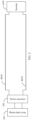
- FIG. 1 is a schematic diagram of a bipolar photovoltaic system according to an embodiment of this application.
- bipolar photovoltaic system includes three buses: a positive direct current bus BUS+, a neutral bus M, and a negative direct current bus BUS-.
- the bipolar photovoltaic system provided in this embodiment of this application only needs to be applicable to a safety regulation of 1500 V, thereby reducing a voltage withstand requirement for a power transistor in a power converter or an inverter.
- An input terminal of a power converter 200 is configured to connect to a photovoltaic array 100.
- a first output terminal of the power converter 200 is connected to a first terminal of the positive direct current bus BUS+.
- a second output terminal of the power converter 200 is connected to a first terminal of the neutral bus M.
- a third output terminal of the power converter 200 is connected to a first terminal of the negative direct current bus BUS-.
- the bipolar photovoltaic system includes at least two inverters: a first inverter 300 and a second inverter 400.
- a first input terminal of the first inverter 300 is connected to a second terminal of the positive direct current bus BUS+, and a second input terminal of the first inverter 300 is connected to a second terminal of the neutral bus M.
- a first input terminal of the second inverter 400 is connected to the second terminal of the neutral bus M, and a second input terminal of the second inverter 400 is connected to a second terminal of the negative direct current bus BUS-.
- FIG. 2 is a schematic diagram of a conventional unipolar photovoltaic system.
- a power converter 200 includes two output terminals. A first output terminal of the power converter 200 is connected to a positive direct current bus BUS+, and a second output terminal of the power converter 200 is connected to a negative direct current bus BUS-.
- an inverter 1000 includes two input terminals. A first input terminal of the inverter 1000 is connected to the BUS+, and a second input terminal of the inverter 1000 is connected to the BUS-. An input terminal of the power converter 200 is connected to a photovoltaic array 100.
- the unipolar photovoltaic system shown in FIG. 2 includes two direct current buses: the BUS+ and the BUS-. If a total voltage of the direct current buses is still 3000 V, a voltage level of the input terminal of the inverter 1000 is 3000 V In this case, a withstand voltage of a power transistor in the inverter 1000 is twice as high as a withstand voltage of a power transistor in a single inverter shown in FIG. 1 . Therefore, in the bipolar photovoltaic system shown in FIG. 1 , a voltage drop that a power device is subject to can be reduced, thereby facilitating device selection.
- a total voltage of the direct current buses corresponding to FIG. 1 is 3000 V A higher voltage corresponds to a smaller current, and further, loss on the direct current buses can be reduced.
- a plurality of groups of bipolar inverters may be connected in parallel.
- M groups of bipolar inverters are connected in parallel, where M is an integer greater than or equal to 2, and each group includes two inverters: a positive inverter and a negative inverter.
- the M groups of bipolar inverters connected in parallel include M ⁇ 2 inverters, for example, 4, 6, or 8 inverters.
- a specific value of M is not specifically limited in this embodiment of this application, and the value of M may be set according to an actual power requirement.
- M is 2, to be specific, two groups of bipolar inverters are connected in parallel, and correspond to four inverters, including two positive inverters and two negative inverters.
- a manner a plurality of inverters connected in parallel are classified into a master and a slave.
- one inverter is a master, and other inverters are all slaves.
- a positive inverter group includes three inverters
- a negative inverter group includes three inverters.
- the three positive inverters connected in parallel one is a master, and the other two are slaves.
- the three negative inverters connected in parallel one is a master, and the other two are slaves.
- a controller When suppressing a circulating current, a controller uses a same control mode for a master and a slave. In this case, no master or slave may be distinguished. In another manner, different control modes are used for a master and a slave. For example, a direct current bus voltage of the master is fixed and remains unchanged. Specifically, the direct current bus voltage of the master may be controlled to be a preset voltage, and a direct current bus voltage of the slave may be adjusted to suppress a circulating current between inverters connected in parallel.
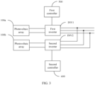
- FIG. 3 is a schematic diagram of a photovoltaic system according to an embodiment of this application.
- the photovoltaic system provided in this embodiment of this application includes a controller and the following at least two inverters.
- a direct current input terminal of each inverter is connected to a corresponding photovoltaic array.
- Alternating current output terminals of the at least two inverters are connected in parallel.
- a power converter may be further included between photovoltaic arrays corresponding to the inverters.
- the power converter may include a boost circuit.
- An implementation type of the power converter is not specifically limited in this embodiment of this application.
- the controller is configured to: obtain a direct current component of a common-mode output current of each of at least one of the at least two inverters, and adjust a direct current bus voltage of the corresponding inverter based on a magnitude of the direct current component, to suppress a circulating current between the at least two inverters.
- the controller herein is a generic term. In actual application, one inverter may correspond to one controller. An implementation form of the controller is not specifically limited in this embodiment of this application. For example, the controller may be a single-chip microcomputer, a microprocessor, or a digital signal processor. A specific location of the controller is not limited in this embodiment of this application. For example, when each inverter corresponds to one controller, the controller may be integrated in the inverter. When a plurality of inverters jointly correspond to one controller, the controller may be independently disposed outside the inverters, and control can be performed provided that the controller can communicate and interact with the inverters.
- the inverters connected in parallel may be inverters in a unipolar photovoltaic system, or may be inverters in a bipolar photovoltaic system, and the technical solution provided in this embodiment of this application may be used to suppress a circulating current between the inverters connected in parallel.
- each inverter corresponds to one controller.
- a first inverter INV1 corresponds to a first controller 500
- a second inverter INV2 corresponds to a second controller 600
- An input terminal of the first inverter INV1 is connected to a corresponding photovoltaic array 100a
- an input terminal of the second inverter INV2 is connected to a corresponding photovoltaic array 100b. That is, each controller independently controls a corresponding inverter.
- the first controller 500 is configured to obtain a first direct current component of a common-mode output current of the first inverter INV1, and the first controller 500 controls a direct current bus voltage of the first inverter INV1 based on the first direct current component of the common-mode output current.
- the second controller 600 is configured to obtain a second direct current component of a common-mode output current of the second inverter INV2, and the second controller 600 controls a direct current bus voltage of the second inverter INV2 based on the second direct current component of the common-mode output current.
- a direct current bus voltage of an inverter is a voltage at a direct current input terminal of the inverter. When a direct current output terminal of the inverter is connected to a power converter, the direct current bus voltage may also be understood as an output voltage of the power converter.
- each controller independently controls an inverter.
- an output current of the inverter is separately detected, a common-mode output current is obtained based on the output current, and then a direct current component is extracted from the common-mode output current.
- the inverter is a three-phase inverter, three-phase output currents of the inverter are separately detected to obtain the common-mode output current, and the direct current component of the common-mode output current is extracted.
- the direct current component in the common-mode output current is extracted, and the direct current bus voltage is adjusted based on the relationship between the direct current component and the direct current bus voltage. This makes direct current bus voltages of a plurality of inverters connected in parallel be equal as much as possible, and therefore suppresses a circulating current between the plurality of inverters connected in parallel.
- a current detection circuit corresponding to each inverter detects three-phase output currents i a , i b , and i c of the inverter in real time. It should be noted that the three-phase output currents of the inverter may be obtained by the current detection circuit, for example, a current sensor. After obtaining the three-phase output currents, the current sensor sends the three-phase output currents to a controller corresponding to the inverter.
- the controller may extract a direct current component from the common-mode output current in any one of the following manners: hardware filtering, software filtering, average value calculation, and fast Fourier transform (FFT, Fast Fourier Transform) calculation, to extract the direct current component from the common-mode output current.
- FFT Fast Fourier transform
- a controller obtains a direct current component of each of three-phase output currents of an inverter, obtains an average value of direct current components of the three-phase output currents based on the direct current component of each of the three-phase output currents of the inverter, and uses the average value as a direct current component of a common-mode output current.
- the first manner of obtaining the direct current component of the common-mode output current is first obtaining the average value of the three-phase output currents, and then extracting a direct current component of the average value as the direct current component of the common-mode output current; and the second manner of obtaining the direct current component of the common-mode output current is first extracting the direct current components of the three-phase output currents, and then obtaining the average value of the direct current components corresponding to three phases as the direct current component of the common-mode output current.
- a controller of each inverter controls a direct current bus voltage based on a direct current component of a common-mode output current.
- a direct current bus voltage of the master may not be controlled, and only a controller of the slave adjusts a direct current bus voltage based on a direct current component of a common-mode output current to suppress a circulating current between the inverters connected in parallel.
- a direct current component of a common-mode output current is referred to as a direct current component for short below.
- FIG. 4 is a schematic diagram of another photovoltaic system according to an embodiment of this application.
- the first inverter serves as a master INV1
- the second inverter serves as a slave INV2.
- the second controller 600 of the slave INV2 obtains a direct current component of a common-mode output current of the slave INV2, and controls a direct current bus voltage of the slave INV2 based on a magnitude of the direct current component, to control a circulating current between the master INV1 and the slave INV2.
- the magnitude of the direct current component determines a magnitude of an adjustment amount of the direct current bus voltage, and the direct current component and the adjustment amount of the direct current bus voltage are in a positive correlation relationship. For example, a larger direct current component indicates a larger adjustment amount of the direct current bus voltage.
- whether adjustment of the direct current bus voltage is being increased or being reduced depends on a positive/negative property of the direct current component, and also depends on an inverter type: a positive inverter or a negative inverter.
- an inverter type a positive inverter or a negative inverter.
- the following first describes two control modes of circulating current suppression for a bipolar photovoltaic system.
- no master or slave is distinguished.
- FIG. 5 is a schematic diagram of a bipolar photovoltaic system according to an embodiment of this application.
- a first inverter 300a and a second inverter 400a in FIG. 5 are equivalent to the first inverter INV1 in FIG. 3
- a third inverter 300b and a fourth inverter 400b in FIG. 5 are equivalent to the second inverter INV2 in FIG. 3 .
- At least two inverters include a positive inverter group and a negative inverter group.
- the positive inverter group includes two inverters
- the negative inverter group includes two inverters.
- the positive inverter group includes at least the first inverter 300a and the third inverter 300b
- the negative inverter group includes at least the second inverter 400a and the fourth inverter 400b.
- a negative direct current input terminal of the first inverter 300a is connected to a positive direct current input terminal of the second inverter 400a.
- a negative direct current input terminal of the third inverter 300b is connected to a positive direct current input terminal of the fourth inverter 400b.
- Alternating current output terminals of the first inverter 300a and the third inverter 300b are connected in parallel, and alternating current output terminals of the second inverter 400a and the fourth inverter 400b are connected in parallel.
- the alternating current output terminals of the first inverter 300a and the third inverter 300b are connected in parallel and are connected to a first primary-side winding of a transformer T1
- the alternating current output terminals of the second inverter 400a and the fourth inverter 400b are connected in parallel and are connected to a second primary-side winding of the transformer T1. That is, all the inverters share one transformer.
- a secondary-side winding of the transformer T1 may be connected to an alternating current power grid.
- an output current of the first inverter 300a reaches an inductor at an output terminal of the third inverter 300b through a filter inductor L1 at an output terminal of the first inverter 300a, a grid-side inductor L2, and a common-mode inductor Lcm, and then reaches an input terminal of the third inverter 300b through a filter capacitor Cflt at the output terminal of the third inverter 300b.
- L1 and L2 are filter inductors, and Lcm is an equivalent common-mode inductor. It should be understood that, in each figure of embodiments of this application, only three inductors are used as an example for description. Alternatively, there may be only one inductor in the system. For example, there may be only one filter inductor. A circulating current between inverters connected in parallel causes power consumption and reduces efficiency. In addition, overcurrent mis-protection may be triggered when the circulating current is large.
- a controller (not shown in the figure) is specifically configured to: obtain a direct current component of a common-mode output current of each of the at least two inverters; if direct current components of the inverters 300a and 300b in the positive inverter group are greater than a preset threshold, reduce a direct current bus voltage of the corresponding inverter, or if direct current components of the inverters 300a and 300b in the positive inverter group are less than the preset threshold, increase a direct current bus voltage of the corresponding inverter; and if direct current components of the inverters 400a and 400b in the negative inverter group are greater than a preset threshold, increase a direct current bus voltage of the corresponding inverter, or if direct current components of the inverters 400a and 400b in the negative inverter group are less than the preset threshold, reduce a direct current bus voltage of the corresponding inverter.
- both the first inverter 300a and the third inverter 300b are positive inverters.
- a direct current component corresponding to the first inverter 300a is greater than the preset threshold, a direct current bus voltage of the first inverter 300a is reduced.
- a direct current component corresponding to the third inverter 300b is less than the preset threshold, a direct current bus voltage of the third inverter 300b is increased.
- a master and a slave are distinguished.
- FIG. 6A is a schematic diagram of another bipolar photovoltaic system according to an embodiment of this application.
- At least two inverters include a positive inverter group and a negative inverter group, the positive inverter group includes at least a first inverter and a third inverter, and the negative inverter group includes at least a second inverter and a fourth inverter.
- a negative direct current input terminal of the first inverter is connected to a positive direct current input terminal of the second inverter.
- a negative direct current input terminal of the third inverter is connected to a positive direct current input terminal of the fourth inverter.
- Alternating current output terminals of the first inverter and the third inverter are connected in parallel, and alternating current output terminals of the second inverter and the fourth inverter are connected in parallel.
- One of the first inverter and the second inverter is a master, and the other is a slave.
- One of the third inverter and the fourth inverter is a master, and the other is a slave.
- the first inverter is a master 300a in the positive inverter group
- the second inverter is a master 400a in the negative inverter group
- the third inverter is a slave 300b in the positive inverter group
- the fourth inverter is a slave 400b in the negative inverter group.
- a controller is specifically configured to: control direct current bus voltages of all the masters (300a and 400a) to be a preset voltage; obtain a direct current component of a common-mode output current of the slave; if a direct current component of the slave (400a) in the positive inverter group is greater than a preset threshold, reduce a direct current bus voltage of the corresponding slave (400a), or if the direct current component of the slave (400a) in the positive inverter group is less than the preset threshold, increase the direct current bus voltage of the corresponding slave (400a); and if a direct current component of the slave (400b) in the negative inverter group is greater than a preset threshold, increase a direct current bus voltage of the corresponding slave (400b), or if the direct current component of the slave (400b) in the negative inverter group is less than the preset threshold, reduce the direct current bus voltage of the corresponding slave (400b).
- a specific value of the preset voltage is not specifically limited in this embodiment of this application.
- the preset voltage needs to ensure that the direct current bus voltage is not too high or too low.
- the value of the preset voltage may be 2 times an effective value of a line voltage of an alternating current-side power grid.
- the four inverters are still used as an example for description.
- the four inverters may include three masters and one slave. The following provides descriptions with reference to accompanying drawings.
- FIG. 6B is a schematic diagram of still another bipolar photovoltaic system according to an embodiment of this application.
- masters include 300a, 400a, and 300b, and a slave is 400b.
- At least two inverters provided in this embodiment of this application include a positive inverter group (300a and 300b) and a negative inverter group (400a and 400b), the positive inverter group includes at least a first inverter and a third inverter, and the negative inverter group includes at least a second inverter and a fourth inverter.
- a negative direct current input terminal of the first inverter is connected to a positive direct current input terminal of the second inverter.
- a negative direct current input terminal of the third inverter is connected to a positive direct current input terminal of the fourth inverter.
- Alternating current output terminals of the first inverter and the third inverter are connected in parallel, and alternating current output terminals of the second inverter and the fourth inverter are connected in parallel.
- Both the first inverter and the third inverter are masters (300a and 300b), one of the second inverter and the fourth inverter is a master, and the other is a slave; or both the second inverter and the fourth inverter are masters, one of the first inverter and the third inverter is a master, and the other is a slave.
- a principle of adjusting the direct current bus voltage is to adjust a sum of direct current bus voltages of the master 300b and the slave 400b to be equal to a sum of direct current bus voltages of the master 300a and the master 400a.
- the direct current bus voltages of the master 300a and the master 400a are both set to a preset voltage and remain unchanged, and a direct current bus voltage of the master 300b is also set to the preset voltage and remains unchanged. Therefore, only a bus voltage of the slave 400b can be adjusted, to make a sum of direct current bus voltages corresponding to a group of bipolar inverters be equal to that of the other group of bipolar inverters.
- a controller is specifically configured to: control direct current bus voltages of all the masters to be a preset voltage; obtain a direct current component of a common-mode output current of the slave; and when the slave is located in the positive inverter group, if the direct current component is greater than a preset threshold, reduce a direct current bus voltage of the slave, or if the direct current component is less than the preset threshold, increase the direct current bus voltage of the slave; or when the slave is located in the negative inverter group, if the direct current component is greater than a preset threshold, increase a direct current bus voltage of the slave, or if the direct current component is less than the preset threshold, reduce the direct current bus voltage of the corresponding slave.
- both positive inverters are masters, and one of the two negative inverters is a slave.
- both negative inverters may be masters, one of the two positive inverters may be a master, and the other may be a slave.
- the two positive inverters include a master 300a and a slave 300b, and the two negative inverters include a master 400a and a master 400b.
- the bipolar photovoltaic system described above is described by using four inverters as an example, and more inverters may be included.
- the following describes a bipolar photovoltaic system corresponding to six inverters when M is 3.
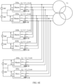
- FIG. 6D is a schematic diagram of still yet another bipolar photovoltaic system according to an embodiment of this application.
- two masters are included: a master 300a in a positive inverter group, and a master 400a in a negative inverter group.
- the positive inverter group includes two slaves: a slave 300b and a slave 300c.
- the negative inverter group includes two slaves: a slave 400b and a slave 400c. That is, six inverters include two masters and four slaves.
- FIG. 6E When the bipolar photovoltaic system includes six inverters, in addition to the implementation solution of FIG. 6D , there is another implementation solution shown in FIG. 6E :
- Six inverters include four masters and two slaves. As shown in FIG. 6E , the four masters are a master 300a, a master 400a, a master 300b, and a master 300c, and the two slaves are a slave 400b and a slave 400c.
- FIG. 6E is merely a schematic diagram, and an example in which all positive inverters are masters and two inverters in a negative inverter group are slaves is used for description.
- all negative inverters may be masters, and four of positive inverters are slaves.
- a controller adjusts a direct current bus voltage of an inverter.
- the controller may reduce an output power; or when the controller needs to reduce the direct current bus voltage, the controller may increase the output power.
- the foregoing describes a case in which an input power of an inverter remains unchanged. There is another case in which an output power of an inverter remains unchanged.
- the control may increase an input power; or when the controller needs to reduce the direct current bus voltage, the controller may reduce the input power.
- the foregoing describes a one-to-one control mode, in other words, is applicable to any inverter that needs to be adjusted.
- the positive inverter group and the negative inverter group jointly correspond to the transformer T1, where the positive inverter group is connected to the first primary-side winding of the transformer T1, the negative inverter group is connected to the second primary-side winding of the transformer T1, and the first primary-side winding and the second primary-side winding share the secondary-side winding.
- positive inverter group and the negative inverter group each may correspond to a separate transformer.
- FIG. 6F is a schematic diagram of a still further bipolar photovoltaic system according to an embodiment of this application.
- a positive inverter group corresponds to a first transformer T1A
- a negative inverter group corresponds to a second transformer T1B.
- a quantity of transformers is not limited. One transformer may be used, or two separate transformers may be used.
- inverters connected in parallel correspond to a direct current DC power supply
- the direct current DC power supply is a photovoltaic array
- the direct current DC power supply may be a wind turbine or an energy storage battery.
- a specific form of a direct current power supply connected to an input terminal of an inverter is not specifically limited in this embodiment of this application.
- the following describes a possible specific implementation by using application in the photovoltaic power generation field as an example.
- FIG. 6G is a schematic diagram of a yet further bipolar photovoltaic system according to an embodiment of this application.
- the photovoltaic system corresponding to FIG. 6G may be applied to a large-sized photovoltaic station.
- a power of an inverter may be high, an input terminal of each inverter may be connected to a corresponding combiner box, and the combiner box may include a power converter.
- each combiner box may include a plurality of power converters connected in parallel.
- An input terminal of each power converter is connected to a corresponding photovoltaic PV array.
- FIG. 6G shows merely an example of a photovoltaic PV array.
- An implementation form of the photovoltaic array is not specifically limited in embodiments of this application.
- the photovoltaic array may include a plurality of photovoltaic strings, and the photovoltaic strings are connected in series and parallel.
- Each photovoltaic string may include photovoltaic panels connected in series or connected in series and parallel.
- a first inverter 300a is connected to a corresponding positive MPPT combiner box 200a as a positive inverter.
- a third inverter 300b is connected to a corresponding positive maximum power point tracking (MPPT, Maximum Power Point Tracking) combiner box 200c as a positive inverter.
- MPPT Maximum Power Point Tracking
- a second inverter 400a is connected to a corresponding negative MPPT combiner box 200b as a negative inverter.
- a fourth inverter 400b is connected to a corresponding negative MPPT combiner box 200d as a negative inverter.
- a photovoltaic system with a low power level may not include a combiner box, an input terminal of an inverter is directly connected to a power converter, and an input terminal of the power converter is connected to a corresponding photovoltaic array.
- a power magnitude and a specific topology of the photovoltaic system are not limited. Provided that there are inverters connected in parallel, circulating current suppression for output terminals of the inverters connected in parallel can be implemented.
- FIG. 7 is a schematic diagram of a unipolar photovoltaic system in which negative electrodes are connected according to an embodiment of this application.
- FIG. 7 that two inverters are connected in parallel is merely used as an example for description. It should be understood that more inverters whose alternating current output terminals are connected in parallel may be alternatively included.
- alternating current output terminals of N inverters are connected in parallel, where N is an integer greater than or equal to 2.
- the alternating current output terminals of the N inverters are connected in parallel and are connected to a primary-side winding of one transformer T.
- an alternating current output terminal of a first inverter 1000a and an alternating current output terminal of a second inverter 1000b are connected in parallel, and a negative direct current input terminal of the first inverter 1000a and a negative direct current input terminal of the second inverter 1000b are connected, in other words, direct current negative electrodes of the two inverters are connected, also referred to as that negative electrodes are connected.
- both inverters are negative inverters.
- a case in which there is a circulating current is as follows:
- the alternating current output terminals of the two inverters form a circulating current loop through a filter inductor L1, a grid-side inductor L2, a common-mode inductor Lcm, and a filter capacitor Cflt, to be specific, from the alternating current output terminal of the first inverter 1000a to the alternating current output terminal of the second inverter 1000b, and then to the direct current input terminal of the second inverter 1000b.
- a current flows from the direct current input terminal of the second inverter 1000b back to the direct current input terminal of the first inverter 1000a.
- a current may flow from the alternating current output terminal of the second inverter 1000b to the alternating current output terminal of the first inverter 1000a. This is not specifically limited in this embodiment of this application.
- control modes provided in embodiments of this application. Two control modes are included.
- a control mode a plurality of inverters connected in parallel are classified into a master and a slave. To be specific, one inverter is a master, and other inverters are all slaves. For example, when three inverters are connected in parallel, one inverter is a master, and the other two inverters are slaves.
- a controller When a controller suppresses a circulating current, in a manner, a same control mode is used for a master and a slave. In another manner, different control modes are used for a master and a slave.
- a direct current bus voltage of the master is fixed and remains unchanged.
- a direct current bus voltage of the master may be controlled to be a preset voltage, and a direct current bus voltage of the slave may be adjusted to suppress a circulating current between inverters.
- the following describes a first manner of circulating current suppression when negative electrodes are connected.
- a controller (not shown in the figure) is specifically configured to: obtain a direct current component of a common-mode output current of each inverter; and when the direct current component is greater than a preset threshold, reduce a direct current bus voltage of the corresponding inverter; or when the direct current component is less than the preset threshold, increase the direct current bus voltage of the corresponding inverter.
- the preset threshold may be set according to a specific circulating current suppression requirement. For example, the preset threshold may be set to 0. To be specific, when the direct current component is greater than 0, the direct current bus voltage is controlled to be reduced; or when the direct current component is less than 0, the direct current bus voltage is controlled to be increased. When the preset threshold is set to 0, a circulating current can be well suppressed. For example, if a direct current component of the first inverter 1000a is greater than 0, a direct current bus voltage of the first inverter 1000a is reduced; and if a direct current component of the second inverter 1000b is less than 0, a direct current bus voltage of the second inverter 1000b is increased.
- control of the direct current bus voltage may be determined by determining a positive/negative property, namely, a direction, of the direct current component, to be specific, determining whether the direct current component flows out of the inverter or flows into the inverter.
- Control modes in embodiments of this application are all for controlling a single inverter.
- the foregoing control mode is used for a master and all slaves.
- an output current of the inverter is separately detected, a common-mode output current is obtained based on the output current, and then a direct current component is extracted from the common-mode output current.
- the inverter is a three-phase inverter, three-phase output currents of the inverter are separately detected to obtain the common-mode output current, and the direct current component of the common-mode output current is extracted.
- the following describes a second manner of circulating current suppression when negative electrodes are connected.
- FIG. 8 is a schematic diagram of a photovoltaic system, corresponding to FIG. 7 , in which a master and a slave are distinguished.
- Negative direct current input terminals of at least two inverters are connected, one of the at least two inverters is a master, and other inverters are slaves.
- two inverters are used as an example for description, and a master and a slave are distinguished: a master 1000a and a slave 1000b. Circulating current suppression is performed only on the slave 1000b, and a magnitude of a direct current bus voltage of the master 1000a may not need to be adjusted.
- each inverter corresponds to one controller
- only a controller corresponding to the slave 1000b suppresses a circulating current.
- the controller obtains a direct current component of a common-mode output current of the slave 1000b; and when the direct current component is greater than a preset threshold, reduces a direct current bus voltage of the slave 1000b; or when the direct current component is less than the preset threshold, increases the direct current bus voltage of the slave 1000b.
- a controller of the master may control the direct current bus voltage of the master 1000a to be a preset voltage.
- the following describes a circulating current suppression solution for a photovoltaic system in which a plurality of inverters are connected in parallel with their positive electrodes connected.
- FIG. 9 is a schematic diagram of a unipolar photovoltaic system in which positive electrodes are connected according to an embodiment of this application.
- Alternating current output terminals of N inverters are connected in parallel, where N is an integer greater than or equal to 2.
- the alternating current output terminals of the N inverters are connected in parallel and are connected to a primary-side winding of one transformer T.
- FIG. 9 that two inverters are connected in parallel is merely used as an example for description.
- an alternating current output terminal of a first inverter 1000a and an alternating current output terminal of a second inverter 1000b are connected in parallel, and a positive direct current input terminal of the first inverter 1000a and a positive direct current input terminal of the second inverter 1000b are connected, in other words, direct current positive electrodes of the two inverters are connected, also referred to as that positive electrodes are connected.
- both inverters are positive inverters.
- a case in which there is a circulating current is as follows:
- the alternating current output terminals of the two inverters form a circulating current loop through a filter inductor L1, a grid-side inductor L2, a common-mode inductor Lcm, and a filter capacitor Cflt, to be specific, from the alternating current output terminal of the first inverter 1000a to the alternating current output terminal of the second inverter 1000b, and then to the direct current input terminal of the second inverter 1000b.
- a current flows from the direct current input terminal of the second inverter 1000b back to the direct current input terminal of the first inverter 1000a.
- a current may flow from the alternating current output terminal of the second inverter 1000b to the alternating current output terminal of the first inverter 1000a. This is not specifically limited in this embodiment of this application.
- a same circulating current suppression manner is used for all inverters connected in parallel. Positive direct current input terminals of at least two inverters are connected.
- a controller obtains a direct current component of a common-mode output current of an inverter; and if the direct current component is greater than a preset threshold, increases a direct current bus voltage of the inverter; or if the direct current component is less than the preset threshold, reduces the direct current bus voltage of the inverter. It can be learned that the circulating current suppression manner for the inverters whose positive electrodes are connected is exactly opposite to the circulating current suppression manner for the inverters whose negative electrodes are connected.
- the preset threshold may be set according to a specific circulating current suppression requirement. For example, the preset threshold may be set to 0. To be specific, when the direct current component is greater than 0, the direct current bus voltage is controlled to be increased; or when the direct current component is less than 0, the direct current bus voltage is controlled to be reduced. When the preset threshold is set to 0, a circulating current can be well suppressed. For example, if a direct current component of the first inverter 1000a is greater than 0, a direct current bus voltage of the first inverter 1000a is reduced; and if a direct current component of the second inverter 1000b is less than 0, a direct current bus voltage of the second inverter 1000b is increased.
- control of the direct current bus voltage may be determined by determining a positive/negative property, namely, a direction, of the direct current component, to be specific, determining whether the direct current component flows out of the inverter or flows into the inverter.
- Control modes in embodiments of this application are all for controlling a single inverter.
- the foregoing control mode is used for a master and all slaves.
- an output current of the inverter is separately detected, a common-mode output current is obtained based on the output current, and then a direct current component is extracted from the common-mode output current.
- the inverter is a three-phase inverter, three-phase output currents of the inverter are separately detected to obtain the common-mode output current, and the direct current component of the common-mode output current is extracted.
- the following describes a second manner of circulating current suppression when negative electrodes are connected.
- FIG. 10 is a schematic diagram of a photovoltaic system, corresponding to FIG. 9 , in which a master and a slave are distinguished.
- a master and a slave are distinguished.
- a direct current bus voltage of the master is not adjusted, and only a direct current bus voltage of the slave is adjusted to suppress a circulating current between the master and the slave and a circulating current between slaves.
- a controller is specifically configured to: obtain a direct current component of a common-mode output current of the slave; if the direct current component is greater than a preset threshold, increase a direct current bus voltage of the slave, or if the direct current component is less than the preset threshold, reduce the direct current bus voltage of the slave; and control a direct current bus voltage of the master to be a preset voltage.
- FIG. 10 two inverters are used as an example for description, and a master and a slave are distinguished: a master 1000a and a slave 1000b. Circulating current suppression is performed only on the slave 1000b, and a magnitude of a direct current bus voltage of the master 1000a may not need to be adjusted.
- the direct current bus voltage of the master is controlled to be a preset voltage and remains unchanged. Specifically, this may be implemented by a controller of the master.
- each inverter corresponds to one controller
- only a controller corresponding to the slave 1000b suppresses a circulating current.
- the controller obtains a direct current component of a common-mode output current of the slave 1000b; and when the direct current component is greater than a preset threshold, increases a direct current bus voltage of the slave 1000b; or when the direct current component is less than the preset threshold, reduces the direct current bus voltage of the slave 1000b.
- the controller of the master may control the direct current bus voltage of the master 1000a to be the preset voltage.
- an embodiment of this application further provides a circulating current suppression method for a photovoltaic system.
- FIG. 11 is a flowchart of a circulating current suppression method for a photovoltaic system according to an embodiment of this application.
- the circulating current suppression method for a photovoltaic system in this embodiment is applied to the following photovoltaic system.
- the photovoltaic system includes at least two inverters, a direct current input terminal of each inverter is connected to a corresponding photovoltaic array, and alternating current output terminals of the at least two inverters are connected in parallel.
- S1101 Obtain a direct current component of a common-mode output current of at least one of the at least two inverters.
- direct current components of common-mode output currents of all the inverters may be obtained, or direct current components of only some of the inverters may be obtained.
- direct current components of only some of the inverters may be obtained.
- only a direct current component of a common-mode output current of the slave may be obtained.
- S1102 Adjust a direct current bus voltage of the corresponding inverter based on a magnitude of the direct current component, to suppress a circulating current between the at least two inverters.
- a direct current component of a common-mode output current of each inverter is detected, and a direct current bus voltage of the inverter is adjusted based on a magnitude of the direct current component in a closed-loop manner, thereby avoiding a circulating current caused by a difference between direct current bus voltages of the inverters connected in parallel.
- no new hardware device needs to be additionally added to resolve the technical problem of the circulating current, implementation is convenient and simple, and costs are low.
- the circulating current suppression method provided in this embodiment of this application is applicable to inverters connected in parallel in a unipolar photovoltaic system, and is also applicable to inverters connected in parallel in a bipolar photovoltaic system.
- the following first describes a circulating current suppression method for inverters connected in parallel in a bipolar photovoltaic system with reference to accompanying drawings.
- FIG. 12 is a flowchart of another circulating current suppression method for a photovoltaic system according to an embodiment of this application.
- the photovoltaic system includes at least four inverters.
- at least two inverters include a positive inverter group and a negative inverter group, the positive inverter group includes at least a first inverter and a third inverter, and the negative inverter group includes at least a second inverter and a fourth inverter; a negative direct current input terminal of the first inverter is connected to a positive direct current input terminal of the second inverter; a negative direct current input terminal of the third inverter is connected to a positive direct current input terminal of the fourth inverter; and alternating current output terminals of the first inverter and the third inverter are connected in parallel, and alternating current output terminals of the second inverter and the fourth inverter are connected in parallel.
- the obtaining a direct current component of a common-mode output current of at least one of the at least two inverters, and adjusting a direct current bus voltage of the corresponding inverter based on a magnitude of the direct current component specifically includes the following steps.
- S1201 Obtain a direct current component of a common-mode output current of each of the at least two inverters.
- S1202 If a direct current component of an inverter in the positive inverter group is greater than a preset threshold, reduce a direct current bus voltage of the corresponding inverter; or if a direct current component of an inverter in the positive inverter group is less than the preset threshold, increase a direct current bus voltage of the corresponding inverter.
- S1203 If a direct current component of an inverter in the negative inverter group is greater than a preset threshold, increase a direct current bus voltage of the corresponding inverter; or if a direct current component of an inverter in the negative inverter group is less than the preset threshold, reduce a direct current bus voltage of the corresponding inverter.
- FIG. 12 corresponds to a case in which no master or slave is distinguished in a bipolar photovoltaic system.
- the following describes a circulating current suppression method for inverters that are connected in parallel and that are distinguished in terms of a master or a slave.
- FIG. 13 is a flowchart of still another circulating current suppression method for a photovoltaic system according to an embodiment of this application.
- the photovoltaic system includes at least four inverters.
- at least two inverters include a positive inverter group and a negative inverter group, the positive inverter group includes at least a first inverter and a third inverter, and the negative inverter group includes at least a second inverter and a fourth inverter; a negative direct current input terminal of the first inverter is connected to a positive direct current input terminal of the second inverter; a negative direct current input terminal of the third inverter is connected to a positive direct current input terminal of the fourth inverter; alternating current output terminals of the first inverter and the third inverter are connected in parallel, and alternating current output terminals of the second inverter and the fourth inverter are connected in parallel; one of the first inverter and the second inverter is a master, and the other is a slave; and one of the third inverter and the fourth inverter is a
- the obtaining a direct current component of a common-mode output current of at least one of the at least two inverters, and adjusting a direct current bus voltage of the corresponding inverter based on a magnitude of the direct current component specifically includes the following steps.
- S1301 Control direct current bus voltages of all the masters to be a preset voltage.
- the direct current bus voltages of the masters may be kept unchanged and do not need to be adjusted, and only a direct current bus voltage of the slave is adjusted to suppress a circulating current between a plurality of inverters connected in parallel.
- S1302 Obtain a direct current component of a common-mode output current of the slave.
- S1304 If a direct current component of the slave in the negative inverter group is greater than a preset threshold, increase a direct current bus voltage of the corresponding slave; or if the direct current component of the slave in the negative inverter group is less than the preset threshold, reduce the direct current bus voltage of the corresponding slave.
- the foregoing describes the circulating current suppression method for a bipolar photovoltaic system, and the following describes a circulating current suppression method for a unipolar photovoltaic system.
- the circulating current suppression method for a unipolar photovoltaic system includes two types based on a connection relationship between inverters. A first type is circulating current suppression for positive inverters, and a second type is circulating current suppression for negative inverters. The following first describes a circulating current suppression method for positive inverters connected in parallel.
- FIG. 14 is a flowchart of a circulating current suppression method for a unipolar photovoltaic system according to an embodiment of this application.
- the circulating current suppression method provided in this embodiment of this application is applicable to positive inverters, to be specific, negative direct current input terminals of at least two inverters are connected. A same control mechanism is used for all the inverters that are not distinguished in terms of a master or a slave.
- the obtaining a direct current component of a common-mode output current of at least one of the at least two inverters, and adjusting a direct current bus voltage of the corresponding inverter based on a magnitude of the direct current component specifically includes the following steps.
- Each inverter is controlled separately without mutual impact.
- Each inverter detects three-phase output currents of the inverter, obtains a direct current component of a common-mode output current based on the three-phase output currents, and adjusts a direct current bus voltage based on the direct current component to suppress a circulating current.
- FIG. 15 is a flowchart of another circulating current suppression method for a unipolar photovoltaic system according to an embodiment of this application.
- At least two inverters are used as an example for description.
- negative direct current input terminals of the at least two inverters are connected, one of the at least two inverters is a master, and other inverters are slaves.
- the obtaining a direct current component of a common-mode output current of at least one of the at least two inverters, and adjusting a direct current bus voltage of the corresponding inverter based on a magnitude of the direct current component specifically includes the following steps.
- S1501 Control a direct current bus voltage of the master to be a preset voltage, and obtain a direct current component of a common-mode output current of each slave.
- the following describes a circulating current suppression method for negative inverters connected in parallel in a unipolar photovoltaic system.
- FIG. 16 is a flowchart of still another circulating current suppression method for a unipolar photovoltaic system according to an embodiment of this application.
- At least two inverters are used as an example for description. Positive direct current input terminals of the at least two inverters are connected. All inverters connected in parallel are not distinguished in terms of a master or a slave. To be specific, a same control policy is used for all the inverters connected in parallel, and current detection and circulating current suppression are performed for each inverter separately.
- the obtaining a direct current component of a common-mode output current of at least one of the at least two inverters, and adjusting a direct current bus voltage of the corresponding inverter based on a magnitude of the direct current component specifically includes the following steps.
- FIG. 17 is a flowchart of yet another circulating current suppression method for a unipolar photovoltaic system according to an embodiment of this application.
- This embodiment provides a circulating current suppression method for negative inverters connected in parallel, and the negative inverters connected in parallel are distinguished in terms of a master or a slave.
- positive direct current input terminals of at least two inverters are connected, one of the at least two inverters is a master, and other inverters are slaves.
- the obtaining a direct current component of a common-mode output current of at least one of the at least two inverters, and adjusting a direct current bus voltage of the corresponding inverter based on a magnitude of the direct current component specifically includes the following steps.
- S1701 Control a direct current bus voltage of the master to be a preset voltage, and obtain a direct current component of a common-mode output current of each slave. It should be understood that there is no chronological order between the controlling the direct current bus voltage of the master and the obtaining the direct current component of the slave in S1701 either; or there may be a chronological order. This is not specifically limited in this embodiment of this application.
- manners of obtaining a direct current component may include the following two manners.
- Obtain a direct current component of each of three-phase output currents of at least one inverter obtain an average value of direct current components of the three-phase output currents based on the direct current component of each of the three-phase output currents, and use the average value as a direct current component of a common-mode output current.
- a control policy used for a positive inverter is as follows: When a direct current component is greater than 0, to be specific, a direction is flowing out from an output terminal of the inverter, it indicates that a direct current bus voltage of the inverter is high. In this case, the direct current bus voltage of the inverter needs to be reduced. When the direct current component is less than 0, to be specific, the direction is flowing from the output terminal of the inverter into the inverter, it indicates that the direct current bus voltage of the inverter is low. In this case, the direct current bus voltage of the inverter needs to be increased.
- a control policy used for a negative inverter is as follows: When a direct current component is greater than 0, to be specific, a direction is flowing out from an output terminal of the inverter, it indicates that a direct current bus voltage of the inverter is low. In this case, the direct current bus voltage of the inverter needs to be increased. When the direct current component is less than 0, to be specific, the direction is flowing from the output terminal of the inverter into the inverter, it indicates that the direct current bus voltage of the inverter is high. In this case, the direct current bus voltage of the inverter needs to be reduced.
- the technical solutions provided in embodiments of this application are not only applicable to a plurality of inverters connected in parallel in a unipolar photovoltaic system, but also applicable to a plurality of inverters connected in parallel in a bipolar photovoltaic system. Because alternating current output terminals of the inverters are connected in parallel, when a circulating current occurs, the circulating current can be suppressed, thereby protecting an output side of the inverters. If there is no voltage difference between a plurality of inverters connected in parallel, there is no circulating current. In embodiments of this application, to suppress a circulating current, a direct current bus voltage is adjusted to reduce or eliminate a voltage difference between inverters connected in parallel.
- At least one (item) means one or more, and "a plurality of means two or more.
- the term “and/or” is used to describe an association relationship between associated objects, and indicates that three relationships may exist. For example, “A and/or B” may indicate the following three cases: Only A exists, only B exists, and both A and B exist, where A and B may be singular or plural.
- the character “/” generally indicates an “or” relationship between the associated objects.
- At least one of the following items (pieces) or a similar expression thereof indicates any combination of these items, including a single item (piece) or any combination of a plurality of items (pieces).
- At least one (piece) of a, b, or c may represent: a, b, c, "a and b", “a and c", “b and c", or "a, b, and c", where a, b, and c may be singular or plural.
Landscapes
- Engineering & Computer Science (AREA)
- Power Engineering (AREA)
- Inverter Devices (AREA)
- Photovoltaic Devices (AREA)
Applications Claiming Priority (1)
| Application Number | Priority Date | Filing Date | Title |
|---|---|---|---|
| PCT/CN2020/136008 WO2022126300A1 (zh) | 2020-12-14 | 2020-12-14 | 一种光伏系统及环流抑制方法 |
Publications (3)
| Publication Number | Publication Date |
|---|---|
| EP4246802A1 true EP4246802A1 (de) | 2023-09-20 |
| EP4246802A4 EP4246802A4 (de) | 2024-03-06 |
| EP4246802B1 EP4246802B1 (de) | 2025-08-27 |
Family
ID=82058730
Family Applications (1)
| Application Number | Title | Priority Date | Filing Date |
|---|---|---|---|
| EP20965321.1A Active EP4246802B1 (de) | 2020-12-14 | 2020-12-14 | Fotovoltaisches system und verfahren zur unterdrückung des zirkulationsstroms |
Country Status (5)
| Country | Link |
|---|---|
| US (1) | US12597850B2 (de) |
| EP (1) | EP4246802B1 (de) |
| CN (1) | CN115176412B (de) |
| AU (1) | AU2020481237A1 (de) |
| WO (1) | WO2022126300A1 (de) |
Families Citing this family (8)
| Publication number | Priority date | Publication date | Assignee | Title |
|---|---|---|---|---|
| CN115606084B (zh) * | 2020-12-31 | 2026-02-24 | 华为数字能源技术有限公司 | 一种逆变器并联系统中的环流抑制方法及装置 |
| WO2022188063A1 (zh) * | 2021-03-10 | 2022-09-15 | 华为数字能源技术有限公司 | 一种光伏系统、逆变器及控制方法 |
| EP4311095A4 (de) * | 2021-03-31 | 2024-05-08 | Huawei Digital Power Technologies Co., Ltd. | Stromversorgungssystem, wechselrichter und verfahren zur steuerung von positiven und negativen busspannungen eines wechselrichters |
| CN113890103B (zh) * | 2021-11-05 | 2022-11-15 | 阳光电源股份有限公司 | 一种光伏系统及控制方法 |
| CN117914007B (zh) * | 2024-03-20 | 2024-06-04 | 国网湖北省电力有限公司电力科学研究院 | 一种构网型储能系统运行监测系统及其监测方法 |
| CN118519066B (zh) * | 2024-05-16 | 2025-04-11 | 苏州贝瓦科技有限公司 | 一种并机逆变器接地漏电流的检测保护方法及检测系统 |
| CN223246323U (zh) * | 2024-06-28 | 2025-08-19 | 宁德时代新能源科技股份有限公司 | 一种电池控制电路和电池系统 |
| CN118763914B (zh) * | 2024-08-30 | 2024-11-15 | 锦浪科技股份有限公司 | 一种逆变器的控制方法、装置、电子设备及存储介质 |
Family Cites Families (15)
| Publication number | Priority date | Publication date | Assignee | Title |
|---|---|---|---|---|
| US7692938B2 (en) * | 2006-09-06 | 2010-04-06 | Northern Power Systems, Inc. | Multiphase power converters and multiphase power converting methods |
| KR100862288B1 (ko) * | 2006-12-19 | 2008-10-13 | 한국철도기술연구원 | 전철변전소 회생인버터의 순환전류감시장치 및 제어방법 |
| CN101980409B (zh) * | 2010-11-25 | 2013-06-19 | 河北工业大学 | 一种光伏并网逆变器 |
| FI125100B (en) * | 2013-11-14 | 2015-06-15 | Abb Technology Oy | Method and apparatus for minimizing inverter current or common-mode voltage |
| CN104242706A (zh) * | 2014-08-27 | 2014-12-24 | 江苏永来福实业有限公司 | 一种mw级光伏逆变器系统拓扑结构 |
| CN104538987B (zh) * | 2014-12-31 | 2017-01-11 | 阳光电源股份有限公司 | 一种光伏逆变器交流侧并联的控制方法及系统 |
| US20180175741A1 (en) * | 2015-06-16 | 2018-06-21 | Npc Tech Aps | A galvanically isolated resonant power converter assembly |
| CN105743434B (zh) * | 2016-04-14 | 2018-03-27 | 特变电工西安电气科技有限公司 | 一种光伏发电系统中光伏组件对地共模电压抑制系统 |
| CN106558977B (zh) * | 2017-01-16 | 2018-09-28 | 阳光电源股份有限公司 | 三相三线制逆变器及其输出电流控制方法和控制系统 |
| CN107508316B (zh) * | 2017-08-24 | 2019-04-16 | 山东大学 | 双层优化全局同步脉冲宽度调制系统及方法 |
| CN108429470A (zh) * | 2018-05-07 | 2018-08-21 | 天津瑞能电气有限公司 | 一种基于直流磁环多变流器并联环流控制方法及系统 |
| US10516365B1 (en) * | 2018-06-20 | 2019-12-24 | Schneider Electric Solar Inverters Usa, Inc. | DC voltage control in renewable energy based multilevel power converter |
| CN109888819B (zh) * | 2019-01-08 | 2021-02-05 | 许继集团有限公司 | 一种光伏发电系统及其控制方法和装置 |
| JP6825637B2 (ja) * | 2019-02-28 | 2021-02-03 | 株式会社安川電機 | 電力変換装置、電力変換システム及び電力変換方法 |
| CN112366970B (zh) * | 2021-01-14 | 2021-04-02 | 深圳市正浩创新科技有限公司 | 逆变系统、逆变系统控制方法和并联逆变系统 |
-
2020
- 2020-12-14 CN CN202080031664.8A patent/CN115176412B/zh active Active
- 2020-12-14 EP EP20965321.1A patent/EP4246802B1/de active Active
- 2020-12-14 WO PCT/CN2020/136008 patent/WO2022126300A1/zh not_active Ceased
- 2020-12-14 AU AU2020481237A patent/AU2020481237A1/en active Pending
-
2023
- 2023-06-02 US US18/328,140 patent/US12597850B2/en active Active
Also Published As
| Publication number | Publication date |
|---|---|
| EP4246802A4 (de) | 2024-03-06 |
| CN115176412B (zh) | 2026-03-17 |
| EP4246802B1 (de) | 2025-08-27 |
| US12597850B2 (en) | 2026-04-07 |
| US20230308009A1 (en) | 2023-09-28 |
| CN115176412A (zh) | 2022-10-11 |
| AU2020481237A1 (en) | 2023-06-22 |
| WO2022126300A1 (zh) | 2022-06-23 |
Similar Documents
| Publication | Publication Date | Title |
|---|---|---|
| EP4246802B1 (de) | Fotovoltaisches system und verfahren zur unterdrückung des zirkulationsstroms | |
| US11275398B2 (en) | DC microgrid for interconnecting distributed electricity generation, loads, and storage | |
| US10263456B1 (en) | Integrated three-port bidirectional DC-DC converter for renewable energy sources | |
| US12355253B2 (en) | Photovoltaic system, protection method, and inverter system | |
| US9515546B2 (en) | Power conversion device having initial charging circuit | |
| US11509239B2 (en) | Conversion device having reduced size and cost | |
| US12483069B2 (en) | Dynamic wireless power supply system with controllable power capacity using energy management circuits | |
| US11984819B2 (en) | Power conversion circuit, inverter, and control method | |
| US11811310B2 (en) | Power conversion system and control method | |
| EP4336697B1 (de) | Fotovoltaisches stromerzeugungssystem | |
| US20220407316A1 (en) | Flexible excitation system and control method therefor | |
| CN117879020A (zh) | 一种卸荷子模块、混合式直流卸荷装置及控制方法 | |
| CN112886818A (zh) | 一种五端口能源路由器控制系统 | |
| Li et al. | A boost-Full-Bridge-type single-Active-bridge isolated AC-DC converter | |
| EP4401279B1 (de) | Leistungsumwandlungsschaltung und steuerungsverfahren dafür, batteriepack und energiespeichersystem | |
| CN119765433A (zh) | 变流器架构及控制方法、电池包、及储能系统 | |
| KR20260044982A (ko) | 발전 장치 시스템 및 이의 제어 방법, 전자기기 및 저장 매체 | |
| Takaoka et al. | Isolated DC to single-phase AC converter with active power decoupling capability for battery storage system | |
| US20200373848A1 (en) | Power converter | |
| EP4050780B1 (de) | Stromversorgungssystem mit einem isolierten kommunikationsgerät | |
| US20240128739A1 (en) | Photovoltaic system, fast shutdown method, and photovoltaic inverter | |
| CN111130198A (zh) | 一种电动汽车的充电系统及方法 | |
| CN215870753U (zh) | 一种基于新型超导储能故障限流器的微电网系统 | |
| Mohan et al. | Fault-Ride-Through operation of 3-Phase DAB Converter Using an Asymmetric Duty-Cycle Modulation Control | |
| CN117220514A (zh) | 多路输入的微型逆变器电路系统及其运行控制方法 |
Legal Events
| Date | Code | Title | Description |
|---|---|---|---|
| STAA | Information on the status of an ep patent application or granted ep patent |
Free format text: STATUS: THE INTERNATIONAL PUBLICATION HAS BEEN MADE |
|
| PUAI | Public reference made under article 153(3) epc to a published international application that has entered the european phase |
Free format text: ORIGINAL CODE: 0009012 |
|
| STAA | Information on the status of an ep patent application or granted ep patent |
Free format text: STATUS: REQUEST FOR EXAMINATION WAS MADE |
|
| 17P | Request for examination filed |
Effective date: 20230614 |
|
| AK | Designated contracting states |
Kind code of ref document: A1 Designated state(s): AL AT BE BG CH CY CZ DE DK EE ES FI FR GB GR HR HU IE IS IT LI LT LU LV MC MK MT NL NO PL PT RO RS SE SI SK SM TR |
|
| REG | Reference to a national code |
Ref country code: DE Ref legal event code: R079 Free format text: PREVIOUS MAIN CLASS: H02S0040320000 Ipc: H02J0003380000 Ref country code: DE Ref legal event code: R079 Ref document number: 602020057795 Country of ref document: DE Free format text: PREVIOUS MAIN CLASS: H02S0040320000 Ipc: H02J0003380000 |
|
| A4 | Supplementary search report drawn up and despatched |
Effective date: 20240205 |
|
| RIC1 | Information provided on ipc code assigned before grant |
Ipc: H02M 5/14 20060101ALN20240130BHEP Ipc: H02M 7/493 20070101ALI20240130BHEP Ipc: H02M 1/12 20060101ALI20240130BHEP Ipc: H02J 3/38 20060101AFI20240130BHEP |
|
| DAV | Request for validation of the european patent (deleted) | ||
| DAX | Request for extension of the european patent (deleted) | ||
| GRAP | Despatch of communication of intention to grant a patent |
Free format text: ORIGINAL CODE: EPIDOSNIGR1 |
|
| STAA | Information on the status of an ep patent application or granted ep patent |
Free format text: STATUS: GRANT OF PATENT IS INTENDED |
|
| RIC1 | Information provided on ipc code assigned before grant |
Ipc: H02M 5/14 20060101ALN20250325BHEP Ipc: H02M 7/493 20070101ALI20250325BHEP Ipc: H02M 1/12 20060101ALI20250325BHEP Ipc: H02J 3/38 20060101AFI20250325BHEP |
|
| INTG | Intention to grant announced |
Effective date: 20250410 |
|
| GRAS | Grant fee paid |
Free format text: ORIGINAL CODE: EPIDOSNIGR3 |
|
| GRAA | (expected) grant |
Free format text: ORIGINAL CODE: 0009210 |
|
| STAA | Information on the status of an ep patent application or granted ep patent |
Free format text: STATUS: THE PATENT HAS BEEN GRANTED |
|
| AK | Designated contracting states |
Kind code of ref document: B1 Designated state(s): AL AT BE BG CH CY CZ DE DK EE ES FI FR GB GR HR HU IE IS IT LI LT LU LV MC MK MT NL NO PL PT RO RS SE SI SK SM TR |
|
| REG | Reference to a national code |
Ref country code: CH Ref legal event code: EP |
|
| P01 | Opt-out of the competence of the unified patent court (upc) registered |
Free format text: CASE NUMBER: UPC_APP_1846_4246802/2025 Effective date: 20250731 |
|
| REG | Reference to a national code |
Ref country code: DE Ref legal event code: R096 Ref document number: 602020057795 Country of ref document: DE |
|
| REG | Reference to a national code |
Ref country code: IE Ref legal event code: FG4D |
|
| REG | Reference to a national code |
Ref country code: NL Ref legal event code: MP Effective date: 20250827 |
|
| PG25 | Lapsed in a contracting state [announced via postgrant information from national office to epo] |
Ref country code: IS Free format text: LAPSE BECAUSE OF FAILURE TO SUBMIT A TRANSLATION OF THE DESCRIPTION OR TO PAY THE FEE WITHIN THE PRESCRIBED TIME-LIMIT Effective date: 20251227 |
|
| PGFP | Annual fee paid to national office [announced via postgrant information from national office to epo] |
Ref country code: DE Payment date: 20251104 Year of fee payment: 6 |
|
| PG25 | Lapsed in a contracting state [announced via postgrant information from national office to epo] |
Ref country code: NO Free format text: LAPSE BECAUSE OF FAILURE TO SUBMIT A TRANSLATION OF THE DESCRIPTION OR TO PAY THE FEE WITHIN THE PRESCRIBED TIME-LIMIT Effective date: 20251127 |
|
| REG | Reference to a national code |
Ref country code: LT Ref legal event code: MG9D |
|
| PG25 | Lapsed in a contracting state [announced via postgrant information from national office to epo] |
Ref country code: PT Free format text: LAPSE BECAUSE OF FAILURE TO SUBMIT A TRANSLATION OF THE DESCRIPTION OR TO PAY THE FEE WITHIN THE PRESCRIBED TIME-LIMIT Effective date: 20251229 |
|
| PG25 | Lapsed in a contracting state [announced via postgrant information from national office to epo] |
Ref country code: FI Free format text: LAPSE BECAUSE OF FAILURE TO SUBMIT A TRANSLATION OF THE DESCRIPTION OR TO PAY THE FEE WITHIN THE PRESCRIBED TIME-LIMIT Effective date: 20250827 |
|
| PG25 | Lapsed in a contracting state [announced via postgrant information from national office to epo] |
Ref country code: HR Free format text: LAPSE BECAUSE OF FAILURE TO SUBMIT A TRANSLATION OF THE DESCRIPTION OR TO PAY THE FEE WITHIN THE PRESCRIBED TIME-LIMIT Effective date: 20250827 Ref country code: NL Free format text: LAPSE BECAUSE OF FAILURE TO SUBMIT A TRANSLATION OF THE DESCRIPTION OR TO PAY THE FEE WITHIN THE PRESCRIBED TIME-LIMIT Effective date: 20250827 |
|
| PG25 | Lapsed in a contracting state [announced via postgrant information from national office to epo] |
Ref country code: GR Free format text: LAPSE BECAUSE OF FAILURE TO SUBMIT A TRANSLATION OF THE DESCRIPTION OR TO PAY THE FEE WITHIN THE PRESCRIBED TIME-LIMIT Effective date: 20251128 |
|
| PG25 | Lapsed in a contracting state [announced via postgrant information from national office to epo] |
Ref country code: SE Free format text: LAPSE BECAUSE OF FAILURE TO SUBMIT A TRANSLATION OF THE DESCRIPTION OR TO PAY THE FEE WITHIN THE PRESCRIBED TIME-LIMIT Effective date: 20250827 |
|
| PG25 | Lapsed in a contracting state [announced via postgrant information from national office to epo] |
Ref country code: LV Free format text: LAPSE BECAUSE OF FAILURE TO SUBMIT A TRANSLATION OF THE DESCRIPTION OR TO PAY THE FEE WITHIN THE PRESCRIBED TIME-LIMIT Effective date: 20250827 |
|
| PG25 | Lapsed in a contracting state [announced via postgrant information from national office to epo] |
Ref country code: PL Free format text: LAPSE BECAUSE OF FAILURE TO SUBMIT A TRANSLATION OF THE DESCRIPTION OR TO PAY THE FEE WITHIN THE PRESCRIBED TIME-LIMIT Effective date: 20250827 Ref country code: BG Free format text: LAPSE BECAUSE OF FAILURE TO SUBMIT A TRANSLATION OF THE DESCRIPTION OR TO PAY THE FEE WITHIN THE PRESCRIBED TIME-LIMIT Effective date: 20250827 |
|
| PG25 | Lapsed in a contracting state [announced via postgrant information from national office to epo] |
Ref country code: RS Free format text: LAPSE BECAUSE OF FAILURE TO SUBMIT A TRANSLATION OF THE DESCRIPTION OR TO PAY THE FEE WITHIN THE PRESCRIBED TIME-LIMIT Effective date: 20251127 |
|
| PG25 | Lapsed in a contracting state [announced via postgrant information from national office to epo] |
Ref country code: ES Free format text: LAPSE BECAUSE OF FAILURE TO SUBMIT A TRANSLATION OF THE DESCRIPTION OR TO PAY THE FEE WITHIN THE PRESCRIBED TIME-LIMIT Effective date: 20250827 |
|
| REG | Reference to a national code |
Ref country code: AT Ref legal event code: MK05 Ref document number: 1831169 Country of ref document: AT Kind code of ref document: T Effective date: 20250827 |
|
| PG25 | Lapsed in a contracting state [announced via postgrant information from national office to epo] |
Ref country code: RO Free format text: LAPSE BECAUSE OF FAILURE TO SUBMIT A TRANSLATION OF THE DESCRIPTION OR TO PAY THE FEE WITHIN THE PRESCRIBED TIME-LIMIT Effective date: 20250827 |
|
| PG25 | Lapsed in a contracting state [announced via postgrant information from national office to epo] |
Ref country code: SM Free format text: LAPSE BECAUSE OF FAILURE TO SUBMIT A TRANSLATION OF THE DESCRIPTION OR TO PAY THE FEE WITHIN THE PRESCRIBED TIME-LIMIT Effective date: 20250827 |
|
| PG25 | Lapsed in a contracting state [announced via postgrant information from national office to epo] |
Ref country code: DK Free format text: LAPSE BECAUSE OF FAILURE TO SUBMIT A TRANSLATION OF THE DESCRIPTION OR TO PAY THE FEE WITHIN THE PRESCRIBED TIME-LIMIT Effective date: 20250827 |
|
| PG25 | Lapsed in a contracting state [announced via postgrant information from national office to epo] |
Ref country code: AT Free format text: LAPSE BECAUSE OF FAILURE TO SUBMIT A TRANSLATION OF THE DESCRIPTION OR TO PAY THE FEE WITHIN THE PRESCRIBED TIME-LIMIT Effective date: 20250827 |
|
| PG25 | Lapsed in a contracting state [announced via postgrant information from national office to epo] |
Ref country code: IT Free format text: LAPSE BECAUSE OF FAILURE TO SUBMIT A TRANSLATION OF THE DESCRIPTION OR TO PAY THE FEE WITHIN THE PRESCRIBED TIME-LIMIT Effective date: 20250827 |