EP4246760A1 - Charge control method, charge control apparatus, and battery-mounted equipment - Google Patents
Charge control method, charge control apparatus, and battery-mounted equipment Download PDFInfo
- Publication number
- EP4246760A1 EP4246760A1 EP22191677.8A EP22191677A EP4246760A1 EP 4246760 A1 EP4246760 A1 EP 4246760A1 EP 22191677 A EP22191677 A EP 22191677A EP 4246760 A1 EP4246760 A1 EP 4246760A1
- Authority
- EP
- European Patent Office
- Prior art keywords
- battery
- charging
- lithium ion
- ion battery
- temperature
- Prior art date
- Legal status (The legal status is an assumption and is not a legal conclusion. Google has not performed a legal analysis and makes no representation as to the accuracy of the status listed.)
- Pending
Links
Images




Classifications
-
- H—ELECTRICITY
- H01—ELECTRIC ELEMENTS
- H01M—PROCESSES OR MEANS, e.g. BATTERIES, FOR THE DIRECT CONVERSION OF CHEMICAL ENERGY INTO ELECTRICAL ENERGY
- H01M10/00—Secondary cells; Manufacture thereof
- H01M10/42—Methods or arrangements for servicing or maintenance of secondary cells or secondary half-cells
- H01M10/44—Methods for charging or discharging
- H01M10/443—Methods for charging or discharging in response to temperature
-
- H—ELECTRICITY
- H01—ELECTRIC ELEMENTS
- H01M—PROCESSES OR MEANS, e.g. BATTERIES, FOR THE DIRECT CONVERSION OF CHEMICAL ENERGY INTO ELECTRICAL ENERGY
- H01M10/00—Secondary cells; Manufacture thereof
- H01M10/42—Methods or arrangements for servicing or maintenance of secondary cells or secondary half-cells
- H01M10/48—Accumulators combined with arrangements for measuring, testing or indicating the condition of cells, e.g. the level or density of the electrolyte
- H01M10/486—Accumulators combined with arrangements for measuring, testing or indicating the condition of cells, e.g. the level or density of the electrolyte for measuring temperature
-
- H—ELECTRICITY
- H02—GENERATION; CONVERSION OR DISTRIBUTION OF ELECTRIC POWER
- H02J—ELECTRIC POWER NETWORKS; CIRCUIT ARRANGEMENTS OR SYSTEMS FOR SUPPLYING OR DISTRIBUTING ELECTRIC POWER; SYSTEMS FOR STORING ELECTRIC ENERGY
- H02J7/00—Circuit arrangements for charging or discharging batteries or for supplying loads from batteries
- H02J7/90—Regulation of charging or discharging current or voltage
- H02J7/971—Regulation of charging or discharging current or voltage the charge cycle being controlled or terminated in response to non-electric parameters
- H02J7/975—Regulation of charging or discharging current or voltage the charge cycle being controlled or terminated in response to non-electric parameters in response to temperature
- H02J7/977—Regulation of charging or discharging current or voltage the charge cycle being controlled or terminated in response to non-electric parameters in response to temperature of the battery
-
- G—PHYSICS
- G01—MEASURING; TESTING
- G01R—MEASURING ELECTRIC VARIABLES; MEASURING MAGNETIC VARIABLES
- G01R31/00—Arrangements for testing electric properties; Arrangements for locating electric faults; Arrangements for electrical testing characterised by what is being tested not provided for elsewhere
- G01R31/36—Arrangements for testing, measuring or monitoring the electrical condition of accumulators or electric batteries, e.g. capacity or state of charge [SoC]
- G01R31/392—Determining battery ageing or deterioration, e.g. state of health
-
- H—ELECTRICITY
- H01—ELECTRIC ELEMENTS
- H01M—PROCESSES OR MEANS, e.g. BATTERIES, FOR THE DIRECT CONVERSION OF CHEMICAL ENERGY INTO ELECTRICAL ENERGY
- H01M10/00—Secondary cells; Manufacture thereof
- H01M10/05—Accumulators with non-aqueous electrolyte
- H01M10/052—Li-accumulators
- H01M10/0525—Rocking-chair batteries, i.e. batteries with lithium insertion or intercalation in both electrodes; Lithium-ion batteries
-
- H—ELECTRICITY
- H01—ELECTRIC ELEMENTS
- H01M—PROCESSES OR MEANS, e.g. BATTERIES, FOR THE DIRECT CONVERSION OF CHEMICAL ENERGY INTO ELECTRICAL ENERGY
- H01M4/00—Electrodes
- H01M4/02—Electrodes composed of, or comprising, active material
- H01M2004/026—Electrodes composed of, or comprising, active material characterised by the polarity
- H01M2004/027—Negative electrodes
-
- H—ELECTRICITY
- H01—ELECTRIC ELEMENTS
- H01M—PROCESSES OR MEANS, e.g. BATTERIES, FOR THE DIRECT CONVERSION OF CHEMICAL ENERGY INTO ELECTRICAL ENERGY
- H01M4/00—Electrodes
- H01M4/02—Electrodes composed of, or comprising, active material
- H01M4/36—Selection of substances as active materials, active masses, active liquids
- H01M4/48—Selection of substances as active materials, active masses, active liquids of inorganic oxides or hydroxides
- H01M4/483—Selection of substances as active materials, active masses, active liquids of inorganic oxides or hydroxides for non-aqueous cells
-
- H—ELECTRICITY
- H02—GENERATION; CONVERSION OR DISTRIBUTION OF ELECTRIC POWER
- H02J—ELECTRIC POWER NETWORKS; CIRCUIT ARRANGEMENTS OR SYSTEMS FOR SUPPLYING OR DISTRIBUTING ELECTRIC POWER; SYSTEMS FOR STORING ELECTRIC ENERGY
- H02J7/00—Circuit arrangements for charging or discharging batteries or for supplying loads from batteries
- H02J7/80—Circuit arrangements for charging or discharging batteries or for supplying loads from batteries including monitoring or indicating arrangements
- H02J7/82—Control of state of charge [SOC]
-
- H—ELECTRICITY
- H02—GENERATION; CONVERSION OR DISTRIBUTION OF ELECTRIC POWER
- H02J—ELECTRIC POWER NETWORKS; CIRCUIT ARRANGEMENTS OR SYSTEMS FOR SUPPLYING OR DISTRIBUTING ELECTRIC POWER; SYSTEMS FOR STORING ELECTRIC ENERGY
- H02J7/00—Circuit arrangements for charging or discharging batteries or for supplying loads from batteries
- H02J7/80—Circuit arrangements for charging or discharging batteries or for supplying loads from batteries including monitoring or indicating arrangements
- H02J7/84—Control of state of health [SOH]
-
- H—ELECTRICITY
- H02—GENERATION; CONVERSION OR DISTRIBUTION OF ELECTRIC POWER
- H02J—ELECTRIC POWER NETWORKS; CIRCUIT ARRANGEMENTS OR SYSTEMS FOR SUPPLYING OR DISTRIBUTING ELECTRIC POWER; SYSTEMS FOR STORING ELECTRIC ENERGY
- H02J7/00—Circuit arrangements for charging or discharging batteries or for supplying loads from batteries
- H02J7/90—Regulation of charging or discharging current or voltage
- H02J7/92—Regulation of charging or discharging current or voltage with prioritisation of loads or sources
-
- H—ELECTRICITY
- H02—GENERATION; CONVERSION OR DISTRIBUTION OF ELECTRIC POWER
- H02J—ELECTRIC POWER NETWORKS; CIRCUIT ARRANGEMENTS OR SYSTEMS FOR SUPPLYING OR DISTRIBUTING ELECTRIC POWER; SYSTEMS FOR STORING ELECTRIC ENERGY
- H02J7/00—Circuit arrangements for charging or discharging batteries or for supplying loads from batteries
- H02J7/90—Regulation of charging or discharging current or voltage
- H02J7/96—Regulation of charging or discharging current or voltage in response to battery voltage
-
- H—ELECTRICITY
- H02—GENERATION; CONVERSION OR DISTRIBUTION OF ELECTRIC POWER
- H02J—ELECTRIC POWER NETWORKS; CIRCUIT ARRANGEMENTS OR SYSTEMS FOR SUPPLYING OR DISTRIBUTING ELECTRIC POWER; SYSTEMS FOR STORING ELECTRIC ENERGY
- H02J7/00—Circuit arrangements for charging or discharging batteries or for supplying loads from batteries
- H02J7/90—Regulation of charging or discharging current or voltage
- H02J7/971—Regulation of charging or discharging current or voltage the charge cycle being controlled or terminated in response to non-electric parameters
-
- Y—GENERAL TAGGING OF NEW TECHNOLOGICAL DEVELOPMENTS; GENERAL TAGGING OF CROSS-SECTIONAL TECHNOLOGIES SPANNING OVER SEVERAL SECTIONS OF THE IPC; TECHNICAL SUBJECTS COVERED BY FORMER USPC CROSS-REFERENCE ART COLLECTIONS [XRACs] AND DIGESTS
- Y02—TECHNOLOGIES OR APPLICATIONS FOR MITIGATION OR ADAPTATION AGAINST CLIMATE CHANGE
- Y02E—REDUCTION OF GREENHOUSE GAS [GHG] EMISSIONS, RELATED TO ENERGY GENERATION, TRANSMISSION OR DISTRIBUTION
- Y02E60/00—Enabling technologies; Technologies with a potential or indirect contribution to GHG emissions mitigation
- Y02E60/10—Energy storage using batteries
Definitions
- Embodiments described herein relate generally to a charge control method, a charge control apparatus, and battery-mounted equipment.
- secondary batteries such as lithium-ion batteries have been mounted on battery-mounted equipment such as smartphones, vehicles, stationary power supplies, robots, and drones.
- batteries in which an oxide containing niobium titanium is used as a negative electrode active material have been used in the battery-mounted equipment to increase the charging capacity and enable rapid charging. Charging and discharging of such batteries are controlled by a controller mounted on or separate from the battery-mounted equipment.
- the life of battery cells in which an active material containing niobium titanium is used as a negative electrode active material is especially likely to decrease when an electric potential of a negative electrode is exposed to a low electric potential. Specifically, even if charging is performed at the same charging voltage, the longer the electric potential of the negative electrode is exposed to a low electric potential, the more likely the battery cell life is to decrease. In addition, the charging capacity of the battery cells in which an active material containing niobium titanium is used as a negative electrode active material tends to increase at higher temperatures. Thus, even if charging is performed at the same charging voltage, the higher the temperature, the more excess lithium ions are inserted, and as a result, the life of the battery cell is likely to decrease. Hence, in order to further extend the life of battery cells while also enabling high-capacity charging, there is a need for charge control that takes the temperature of the battery cells into account.
- a charge control method includes acquiring a measured temperature of a lithium ion battery, acquiring a threshold value for stopping charging of the lithium ion battery according to the measured temperature of the lithium ion battery based on a relationship between a cycle life and a charging capacity of the lithium ion battery for each temperature of the lithium ion battery, and, charging the lithium ion battery based on the threshold value.
- FIG. 1 is a diagram showing an example of a charge control apparatus according to each embodiment.
- a charge control apparatus 1 includes a battery 2 and a management apparatus 3.
- the battery 2 is mounted on a battery pack 5.
- the battery 2 is, for example, arranged in a state of being constrained to a housing (not shown) of the battery pack 5.
- the battery pack 5 is mounted on battery-mounted equipment 6.
- Examples of the battery-mounted equipment 6 include a smartphone, a vehicle, a stationary power supply, a robot, and a drone.
- Examples of the vehicle as the battery-mounted equipment 6 include an electric vehicle, a plug-in hybrid vehicle, and an electric motorcycle.
- an example of the robot on which the battery 2 is mounted is a transport robot such as an automated guided vehicle (AGV) used in factories, etc. At least the battery 2 may not be mounted on the charge control apparatus 1. In this case, the charge control apparatus 1 may control the battery 2 using communications, etc.
- AGV automated guided vehicle
- the battery 2 may be formed of a single cell, or may be formed of a cell block or battery module in which a plurality of single cells are electrically coupled.
- the battery 2 may have an in-series coupling structure in which a plurality of single cells are coupled in series, an in-parallel coupling structure in which a plurality of single cells are coupled in parallel, or both the in-series and in-parallel coupling structures.
- the battery 2 may be a storage battery in which a plurality of battery modules are electrically coupled.
- the battery 2 may have an in-series coupling structure in which multiple battery modules are coupled in series, an in-parallel coupling structure in which multiple battery modules are connected in parallel, or both the in-series and in-parallel coupling structures.
- a single cell is, for example, a battery cell that forms a lithium ion battery.
- a single cell has an electrode group.
- the electrode group has a positive electrode and a negative electrode.
- a separator is interposed between the positive electrode and the negative electrode.
- the separator is formed from an electrically insulating material, and electrically insulates the positive electrode from the negative electrode. Examples of the separator include, but are not limited to, a porous film made of synthetic resin, a non-woven fabric, etc.
- the positive electrode includes a positive electrode current collector such as a positive electrode current collecting foil, and a positive electrode active material-containing layer supported on a surface of the positive electrode current collector.
- the positive electrode current collector is, but is not limited to, for example, an aluminum foil or an aluminum alloy foil.
- a thickness of the positive electrode current collector is, for example, about 10 ⁇ m to 20 ⁇ m.
- the positive electrode active material-containing layer includes a positive electrode active material, and may optionally contain a binding agent and a conductive agent. Examples of the positive electrode active material include, but are not limited to, an oxide, a sulfide, and a polymer, which can occlude and release lithium ions.
- the positive electrode active material includes, for example, at least one selected from a group consisting of a manganese dioxide, an iron oxide, a copper oxide, a nickel oxide, a lithium-manganese composite oxide, a lithium-nickel composite oxide, a lithium-cobalt composite oxide, a lithium-nickel-cobalt composite oxide, a lithium-manganese-cobalt composite oxide, a spinel-type lithium-manganese-nickel composite oxide, a lithium-phosphorus oxide having an olivine structure, an iron sulfate, and a vanadium oxide.
- the positive electrode current collector also includes a positive electrode current collecting tab as a portion where the positive electrode active material-containing layer is unsupported.
- the negative electrode includes a negative electrode current collector, such as a negative electrode current collecting foil, and a negative electrode active material-containing layer supported on a surface of the negative electrode current collector.
- the negative electrode current collector is, but is not limited to, for example, an aluminum foil, an aluminum alloy foil, or a copper foil.
- a thickness of the negative electrode current collector is, for example, about 10 ⁇ m to 20 ⁇ m.
- the negative electrode active material-containing layer includes a negative electrode active material, and may optionally contain a binding agent and a conductive agent. Examples of the negative electrode active material include, but are not particularly limited to, a metal oxide, a metal sulfide, a metal nitride, and a carbonaceous material, which can occlude and release lithium ions.
- the metal oxide as the negative electrode active material examples include a titanium-containing oxide.
- the titanium-containing oxide as the negative electrode active material include, for example, a titanium oxide, a lithium-titanium-containing composite oxide, a niobium-titanium-containing composite oxide, and a sodium-niobium-titanium-containing composite oxide.
- the carbonaceous material as the negative electrode active material include graphite, etc.
- the negative electrode active material is preferably a niobium-containing oxide, such as a niobium-titanium-containing composite oxide and a sodium-niobium-titanium-containing composite oxide. The use of an oxide containing niobium for the negative electrode active material allows rapid charging while increasing the charging capacity.
- the negative electrode current collector includes a negative electrode current collecting tab as a portion where the negative electrode active material-containing layer is unsupported.
- the battery 2 may be coupled to a power source and/or load 7.
- the battery 2 When the power source is coupled to the battery 2, the battery 2 is charged by power supply from the power source.
- the load When the load is coupled to the battery 2, the battery 2 supplies power to drive the load.
- the power source may be a battery separate from the battery 2, or may be a generator, etc.
- the load may be a motor, light, etc.
- a capacitor may be coupled to the battery 2 instead of or in addition to the load.
- the capacitor may store power supplied from the battery 2.
- a motor generator may be coupled to the battery 2. In this case, the battery 2 can supply power to the motor generator and is charged by receiving power from the motor generator.
- the motor generator can operate as both the power source and the load.
- the power source and/or load 7 is mounted on the battery-mounted equipment 6, but is not limited thereto.
- the power source and/or load 7 may be provided outside the battery-mounted equipment 6.
- the management apparatus 3 is an apparatus that manages the battery 2.
- the management apparatus 3 may operate as, for example, a charge control apparatus that controls charging of the battery 2. Further, the management apparatus 3 may operate as, for example, a discharge control apparatus that controls discharging of the battery 2.
- the management apparatus 3 has a controller 10.
- the management apparatus 3 is mounted on the battery-mounted equipment 6, and constitutes a processing apparatus (computer) in the battery-mounted equipment 6.
- the controller 10 of the management apparatus 3 includes a processor and a memory.
- the processor is constituted by a central processing unit (CPU), a graphics processing unit (GPU), a micro processing unit (MPU), etc.
- the processor may be constituted by an application specific integrated circuit (ASIC), a field programmable gate array (FPGA), a digital signal processor (DSP), etc. There may be two or more processors instead of one.
- the memory includes a read only memory (ROM) and a random access memory (RAM).
- the ROM may store a startup program, an adjustment parameter, etc. of the management apparatus 3.
- the RAM may be used as a work memory during processing by the processor.
- the management apparatus 3 may be provided outside the battery-mounted equipment 6.
- the management apparatus 3 may be a server, etc. provided outside the battery-mounted equipment 6.
- the controller 10 of the battery-mounted equipment 6 performs necessary processing while communicating with the management apparatus 3 provided outside the battery-mounted equipment 6.
- the server may be constituted as a cloud server constituted in a cloud environment.
- An operation equivalent to that of the management apparatus 3 may be realized by cooperation of internal and external processing apparatuses of the battery-mounted equipment 6.
- a server outside the battery-mounted equipment 6 serves as a master processing apparatus
- a processing apparatus mounted on the battery-mounted equipment 6 serves as a slave processing apparatus to realize the operation of the management apparatus 3 as a whole.
- the battery pack 5 includes a drive circuit 11.
- the drive circuit 11 causes power supply from the battery 2 to the load to be implemented based on control of the controller 10.
- the drive circuit 11 causes power supply from the power source to the battery 2 to be implemented based on control of the controller 10.
- the drive circuit 11 may include a relay circuit. The relay circuit switches the coupling of the battery 2 to either the power source or the load.
- the drive circuit 11 includes a conversion circuit. The conversion circuit converts power from the power source into direct-current power to be supplied to the battery. In addition, the conversion circuit converts direct-current power from the battery into power to be supplied to the load.
- the conversion circuit can include a voltage transformer circuit, a DC/AC conversion circuit, and an AC/DC transformer circuit.
- the drive circuit 11 may be provided outside the battery pack 5.
- the battery pack 5 includes a current detection circuit 12, a voltage detection circuit 13, and a temperature sensor 14.
- the current detection circuit 12, the voltage detection circuit 13, and the temperature sensor 14 form, for example, a measurement circuit mounted on the battery pack 5. By the measurement circuit, parameters associated with the battery 2 are measured.
- the current detection circuit 12 detects a current flowing to the battery 2 in each of charging, discharging, etc. of the battery 2.
- the voltage detection circuit 13 detects a voltage of the battery 2 in each of charging, discharging, etc. of the battery 2.
- the temperature sensor 14 is a temperature sensor such as a thermocouple and a thermistor, and detects a temperature of the battery 2 in each of charging, discharging, etc. of the battery 2.
- the current detection circuit 12, the voltage detection circuit 13, and the temperature sensor 14 may each make measurements in units of single cells.
- the current detection circuit 12, the voltage detection circuit 13, and the temperature sensor 14 may each make measurements in units of cell blocks or battery modules.
- the current detection circuit 12, the voltage detection circuit 13, and the temperature sensor 14 are mounted on the battery pack 5.
- the current detection circuit 12 and the voltage detection circuit 13 may be provided outside the battery pack 5.
- the temperature sensor 14 may be provided inside the battery 2.
- the temperature sensor 14 may be provided for each single cell, may be provided for each cell block, or may be provided for each battery module.
- the battery-mounted equipment 6 includes a storage 15.
- the storage 15 may be, for example, constituted by a storage device such as a flash memory.
- the storage 15 stores a program to be executed by the controller 10.
- the storage 15 also stores information indicating a relationship between a temperature and a maximum charging capacity of the battery.
- the storage 15 may be a storage device such as a hard disk and a solid state drive.
- the storage 15 may be a magnetic disk, an optical disk (CD-ROM, CD-R, DVD, etc.), a magnetooptical disk (MO, etc.), etc.
- the information stored in the storage 15 may be stored in a server coupled via a network such as the Internet or a server in a cloud environment. In this case, the controller 10 acquires necessary information via the network.
- the battery-mounted equipment 6 includes a user interface 16.
- the user interface 16 includes an operation device that accepts operations by a user of the battery-mounted equipment 6.
- the user interface 16 also includes a presentation device that presents various information to the user of the battery-mounted equipment 6.
- the operation device may include various operation devices such as a button, a dial, and a touch panel.
- the presentation device may include various presentation devices such as a display and a speaker.
- FIG. 2 is a diagram showing an example of a relationship between a cycle life of a battery and a temperature of the battery for each negative electrode active material.
- An abscissa axis of FIG. 2 indicates a reciprocal of the battery temperature (absolute temperature).
- an ordinate axis of FIG. 2 indicates a value obtained by taking a natural logarithm of the cycle life.
- the cycle life is the number of cycles in which degradation of the maximum charging capacity exceeds a certain threshold value. The number of cycles is counted one time when charging from a fully discharged state to a fully charged state and discharging from the fully charged state to a fully discharged state are performed one time each.
- the cycle life and the battery temperature follow the Arrhenius equation.
- the natural logarithm of the cycle life is proportional to the reciprocal of the battery temperature.
- the relationship between the cycle life and the battery temperature is plotted for each kind of negative electrode active material in graphs A1, A2, B, and C in FIG. 2 .
- the graphs of A1 and A2 in FIG. 2 are those when a niobium titanium oxide (NTO) is used as the negative electrode active material.
- B in FIG. 2 is a graph when a lithium titanate (LTO) is used as the negative electrode active material.
- C in FIG. 2 is a graph when a carbonaceous material is used as the negative electrode active material.
- A2 in FIG. 2 is a graph when an NTO with a long-life design, in which the cycle life is prioritized over the charging capacity, is used.
- A2 in FIG. 2 is a graph when an NTO with a high-capacity design, in which the charging capacity is prioritized over the cycle life, is used.
- the NTO with a high-capacity design can be, for example, an NTO having a monoclinic crystal structure.
- the NTO having a monoclinic crystal structure achieves a higher capacity because lithium diffusion is faster than in NTOs having other crystal structures.
- the natural logarithm of the cycle life is proportional to the reciprocal of the battery temperature. Therefore, the graphs A1, A2, B, and C are all nearly straight lines. On the other hand, inclinations of the graphs A1 and A2 are larger than those of the graphs B and C. This indicates that a decrease in cycle life with increasing temperature when the NTO is used as the negative electrode active material is greater than when the LTO or carbonaceous material is used as the negative electrode active material. The reason for this is that when the NTO is used as the negative electrode active material, lithium diffusion tends to be easier at high temperatures than when the LTO or carbonaceous material is used as the negative electrode active material.
- the inclination of the graph A2 for the high-capacity design NTO is larger than that of the graph A1 for the long-life design NTO.
- a difference between the inclinations of the graphs A1 and A2 is much smaller than that between the inclinations of the graphs A1 and A2 and those of the graphs B and C. This means that a main reason for the larger decrease in cycle life with the increasing battery temperature is not the difference in NTO design, but the use of the NTO as the negative electrode active material.
- batteries A1 and A2 using lithium-nickel-manganese-cobalt oxide LiNi 1/3 Mn 1/3 Co 1/3 O 2 as the positive electrode and a niobium-titanium oxide Nb 2 TiO 7 as the negative electrode were prepared.
- A1 is a long-life design battery with a positive electrode/negative electrode ratio of excess negative electrodes.
- A2 is a high-capacity design battery with a nearly equal positive electrode to negative electrode ratio.
- batteries A3, A4, B, and C were prepared for comparison.
- A3 is a battery using a niobium-tungsten oxide Ti 2 Nb 10 W 5 O 4 as the negative electrode.
- A4 is a battery using a niobium-molybdenum oxide TiNb 5 Mo 2 O 20 as the negative electrode.
- B is a battery using lithium titanate Li 4 Ti 5 O 12 as a negative electrode active material.
- C is a battery using graphite as a negative electrode active material.
- Degradation of the negative electrode of a lithium ion battery with an inclination exceeding 4500 is more accelerated than that of the negative electrode of a lithium ion battery with an inclination of less than 4500. This is considered to be due to the fact that in negative electrode materials with an inclination exceeding 4500, a charged state of the positive electrode and the negative electrode tends to vary, making a degradation mechanism more complex and accelerating the degradation. Therefore, the charge control of the embodiment is highly effective in improving the cycle life at high temperatures, especially with the negative electrode containing a high valence such as niobium, tungsten, and molybdenum.
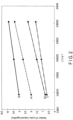
- FIG. 3 is a diagram showing an example of a relationship among a temperature, a cycle life, and a charging capacity of a battery.
- FIG. 3 shows, for example, a cycle life estimated in a case of repeating charging of an NTO at various maximum charging capacities at a battery temperature of 25 °C.
- the charging capacity on the abscissa axis of FIG. 3 is expressed as a percentage with a fully charged state as 100. Therefore, the charging capacity on the abscissa axis of FIG. 3 is equal to a charging rate.
- the charging rate and the cycle life are nearly proportional to each other.
- FIG. 3 shows that at a temperature of 25 °C, the cycle life is about 4800 cycles when charging is repeated to the charging capacity of 100, i.e., to the fully charged state.
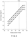
- FIG. 4 is a graph showing a relationship among the temperature, the charging capacity, and an end-of-charge voltage of the battery 2 as an example of the information stored in the storage 15 in the first embodiment.
- the graph in FIG. 4 can be generated by collecting the graph in FIG. 3 for each temperature of the battery 2 and calculating an end-of-charge voltage according to a charging capacity of each of the collected graphs.
- the charging capacity on the abscissa axis of FIG. 4 is expressed as a percentage with a fully charged state as 100. Therefore, the charging capacity on the abscissa axis of FIG. 4 is equal to a charging rate.
- the controller 10 acquires the end-of-charge voltage according to the temperature of the battery 2 detected by the temperature sensor 14 and controls the charging of the battery 2.
- the information stored in the storage 15 is not limited to being stored in the form of the graph shown in FIG. 4 .
- the information stored in the storage 15 may be in a form other than the graph, such as in a form of a table showing the temperature, charging capacity, and end-of-charge voltage of the battery 2 shown in FIG. 4 .
- FIG. 5 is a flowchart showing a charging operation in the charge control apparatus 1 of the first embodiment.
- the processing in FIG. 5 is performed by the controller 10, for example.
- the controller 10 for example.
- step S1 the controller 10 acquires a temperature of the battery 2 that is measured by the temperature sensor 14.
- the temperature sensor 14 may make measurements in units of single cells, in units of cell blocks, or in units of battery modules.
- the controller 10 acquires the highest temperature among the measured temperatures. This is because, when considering controlling the charging of each single cell with the same end-of-charge voltage, controlling the charging based on the single cell with the highest cell temperature, i.e., the lowest end-of-charge voltage, will more greatly suppress the decrease in life.
- step S2 the controller 10 refers to the graph in FIG. 4 to acquire an end-of-charge voltage Vmax at which the charging capacity corresponding to the acquired temperature becomes 100. For example, if the acquired temperature is 45 °C, the controller 10 acquires an end-of-charge voltage Vmax at an intersection of the 45 °C line and Cmax. An end-of-charge voltage for a temperature not stored in the storage 15 can be acquired by interpolation or extrapolation based on the graph in FIG. 4 . For example, an end-of-charge voltage at 30 °C is calculated as an average value of an end-of-charge voltage at 25 °C and an end-of-charge voltage at 35 °C.
- step S3 the controller 10 controls the drive circuit 11 to start charging of the battery 2.
- the charging may be performed, for example, by a constant-current method.
- the constant-current method is a method that supplies power to the battery 2 so that a current flowing through the battery 2 is constant.
- the controller 10 performs charging while monitoring a charging current and a charging voltage of the battery 2 by means of the current detection circuit 12 and the voltage detection circuit 13.
- step S4 the controller 10 acquires a charging voltage V of the battery 2 from the voltage detection circuit 13. Acquisition of the charging voltage V may be performed for each predetermined sampling period.
- step S5 the controller 10 determines if V ⁇ Vmax. In step S5, if V ⁇ Vmax does not hold true, the process returns to step S4. In this case, the charging is continued. In step S5, if V ⁇ Vmax, the controller 10 controls the drive circuit 11 to stop the charging of the battery 2. The controller 10 then ends the processing in FIG. 5 .
- the charging of the battery 2 is controlled with the end-of-charge voltage according to the temperature of the battery 2. Specifically, the charging of the battery 2 is controlled with a lower end-of-charge voltage as the temperature of the battery 2 becomes higher. This allows the charging to be controlled at a maximally high charging capacity that suppresses excessive lithium insertion at each temperature, resulting in both high capacity and long life.
- an oxide containing niobium is used as a negative electrode active material
- an effect of a decrease in cycle life due to temperature is significant. Therefore, the technique of the first embodiment is particularly effective when the effect of the decrease in cycle life due to temperature is significant in the case where an oxide containing niobium is used as the negative electrode active material, etc.
- the technique of the first embodiment is also applicable to cases in which an oxide containing niobium is not used as a negative electrode active material.
- the stopping of the charging of the battery 2 is determined based on the charging voltage.
- the stopping of the charging of the battery 2 may be determined based on the charging capacity.
- the graph in FIG. 3 for each temperature is stored in the storage 15 instead of the graph in FIG. 4 .
- the controller 10 acquires a maximum charging capacity as a threshold value for stopping the charging instead of the end-of-charge voltage in step S2 and acquires the charging capacity in step S3.
- the controller 10 determines if Ccharge - Cmax ⁇ 0 in step S4, and if Ccharge - Cmax ⁇ 0, stops the charging of the battery 2.
- the battery 2 may be charged by a constant-current/constant-voltage method instead of the constant-current method.
- the constant-current/constant-voltage method is a method in which charging is performed at a constant current until a charging voltage reaches a certain threshold voltage, and after the charging voltage reaches the threshold voltage, charging is performed by controlling a charging current so that the charging voltage becomes an end-of-charge voltage.
- the controller 10 can determine whether or not to stop the charging based on whether or not the charging current reaches zero. Therefore, in the constant-current/constant-voltage method, there can be two threshold values for stopping the charging: the threshold value for the charging voltage and the threshold value for the charging current.
- the charging is controlled according to the temperature so that the charging capacity becomes 100.
- the maximum charging capacity is set to be low even at the same temperature, the decrease in cycle life becomes small.
- charging with a charging capacity exceeding 100 can also be performed by increasing the end-of-charge voltage.
- the second embodiment is an example that enables the use of a mode that prioritizes the cycle life and a mode that prioritizes the charging capacity.
- FIG. 6 is a graph showing information on a relationship among a temperature, a cycle life, and an end-of-charge voltage of a battery as an example of information further stored in the storage 15 in the second embodiment.
- the charging capacity and the cycle life are nearly proportional to each other.
- the charging capacity and the end-of-charge voltage are nearly proportional to each other. Therefore, as shown in FIG. 6 , under a constant temperature condition, the end-of-charge voltage and the cycle life are also nearly proportional to each other.
- an end-of-charge voltage that can satisfy a condition of a given cycle life can be acquired from the graph of FIG. 6 .
- an end-of-charge voltage that can satisfy a condition of a given charging capacity can be acquired from the graph of FIG. 4 .
- a cycle life in a case where charging with a charging capacity of 100, i.e., at an end-of-charge voltage of 3.0 V, is repeated is about 4800 cycles.
- the end-of-charge voltage should be set to be lower than 3.0 V.
- the end-of-charge voltage is set at 2.95 V so that the cycle life is extended to about 10000 cycles.
- the cycle life is calculated as an average value in a case of assuming that charging that also includes an end-of-charge voltage set in the past is performed.
- FIG. 7 is a flowchart showing a charging operation in a charge control apparatus 1 of the second embodiment.
- the processing in FIG. 7 is performed by the controller 10, for example.
- step S11 the controller 10 acquires a temperature of the battery 2 that is measured by the temperature sensor 14. In the same manner as in the first embodiment, when the temperatures of multiple locations in the battery 2 are measured, the controller 10 acquires the highest temperature among the measured temperatures.
- step S12 the controller 10 determines whether or not a charging mode of the battery 2 is a long-life mode.
- the long-life mode and a high-capacity mode are prepared as the charging mode of the battery 2.
- the long-life mode is a mode in which the cycle life is prioritized over the charging capacity.
- an end-of-charge voltage is set so that the cycle life is a certain set value, e.g., 10000 cycles.
- the high-capacity mode is a mode in which the charging capacity is prioritized over the cycle life.
- an end-of-charge voltage is set so that the charging capacity is set to a certain set value, e.g., 120.
- step S12 Designation of the long-life mode and the high-capacity mode is made, for example, by an operation of the operation device by the user of the battery-mounted equipment 6.
- step S12 if it is determined that the charging mode of the battery 2 is the long-life mode, the process proceeds to step S13.
- step S12 if it is determined that the charging mode of the battery 2 is not the long-life mode, i.e., is the high-capacity mode, the process proceeds to step S14.
- a normal mode may be prepared as the charging mode of the battery 2.
- the normal mode is, for example, a mode in which charging is controlled so that the charging capacity is 100 and the decrease in life is suppressed in the same manner as described in the first embodiment.
- a current charging mode may be presented to the user by the presentation device.
- step S13 the controller 10 acquires an end-of-charge voltage Vmax that satisfies a condition of a cycle life in the long-life mode based on the acquired temperature.
- step S14 the controller 10 acquires an end-of-charge voltage Vmax that satisfies a condition of a charging capacity in the high-capacity mode based on the acquired temperature.
- step S15 the process proceeds to step S15.
- stopping of charging may be determined based on the charging capacity.
- the controller 10 may acquire a maximum charging capacity according to the temperature instead of the end-of-charge voltage.
- step S15 the controller 10 controls the drive circuit 11 to start charging of the battery 2.
- the charging may be performed, for example, by a constant-current method as in the first embodiment.
- the charging may be performed by a constant-current/constant-voltage method as in the first embodiment. In the following, a description is given assuming that the charging is performed by the constant-current method.
- step S16 the controller 10 acquires a charging voltage V of the battery 2 from the voltage detection circuit 13. Acquisition of the charging voltage V may be performed for each predetermined sampling period.
- step S17 the controller 10 determines if V ⁇ Vmax. In step S17, if V ⁇ Vmax does not hold true, the process returns to step S16. In this case, the charging is continued. In step S17, if V ⁇ Vmax, the controller 10 controls the drive circuit 11 to stop the charging of the battery 2. Then, the controller 10 ends the processing in FIG. 7 .
- the end-of-charge voltage according to the cycle life condition or charging capacity condition is set. This allows charging control to be implemented according to a request of the user.
- the temperature of the battery 2 is taken into account in setting the end-of-charge voltage in both the long-life mode and the high-capacity mode. Therefore, not only in the long-life mode, but even in the high-capacity mode, excessive charging is suppressed to extend the life.
- the set value of the cycle life may be designated by the user.
- the set value of the charging capacity may be designated by the user.
- Such designations can be, for example, made by an operation of the operation device by the user of the battery-mounted equipment 6.
- charge control can be implemented more in accordance with the user's request.
Landscapes
- Engineering & Computer Science (AREA)
- Power Engineering (AREA)
- Chemical & Material Sciences (AREA)
- Chemical Kinetics & Catalysis (AREA)
- Electrochemistry (AREA)
- General Chemical & Material Sciences (AREA)
- Manufacturing & Machinery (AREA)
- Charge And Discharge Circuits For Batteries Or The Like (AREA)
- Secondary Cells (AREA)
- Inorganic Chemistry (AREA)
- Materials Engineering (AREA)
Abstract
A charge control method includes acquiring a measured temperature of a lithium ion battery, acquiring a threshold value for stopping charging of the lithium ion battery according to the measured temperature of the lithium ion battery based on a relationship between a cycle life and a charging capacity of the lithium ion battery for each temperature of the lithium ion battery, and charging the lithium ion battery based on the threshold value.
Description
- Embodiments described herein relate generally to a charge control method, a charge control apparatus, and battery-mounted equipment.
- In recent years, secondary batteries such as lithium-ion batteries have been mounted on battery-mounted equipment such as smartphones, vehicles, stationary power supplies, robots, and drones. Also, in recent years, batteries in which an oxide containing niobium titanium is used as a negative electrode active material have been used in the battery-mounted equipment to increase the charging capacity and enable rapid charging. Charging and discharging of such batteries are controlled by a controller mounted on or separate from the battery-mounted equipment.
- The life of battery cells in which an active material containing niobium titanium is used as a negative electrode active material is especially likely to decrease when an electric potential of a negative electrode is exposed to a low electric potential. Specifically, even if charging is performed at the same charging voltage, the longer the electric potential of the negative electrode is exposed to a low electric potential, the more likely the battery cell life is to decrease. In addition, the charging capacity of the battery cells in which an active material containing niobium titanium is used as a negative electrode active material tends to increase at higher temperatures. Thus, even if charging is performed at the same charging voltage, the higher the temperature, the more excess lithium ions are inserted, and as a result, the life of the battery cell is likely to decrease. Hence, in order to further extend the life of battery cells while also enabling high-capacity charging, there is a need for charge control that takes the temperature of the battery cells into account.
-
-
FIG. 1 is a diagram showing an example of a charge control apparatus according to each embodiment. -
FIG. 2 is a diagram showing an example of a relationship between a cycle life of a battery and a temperature of the battery for each negative electrode active material. -
FIG. 3 is a diagram showing an example of a relationship among a temperature, a cycle life, and a charging capacity of a battery. -
FIG. 4 is a diagram showing an example of information stored in a storage in a first embodiment. -
FIG. 5 is a flowchart showing a charging operation in a charge control apparatus of the first embodiment. -
FIG. 6 is a diagram showing an example of information further stored in a storage in a second embodiment. -
FIG. 7 is a flowchart showing a charging operation in a charge control apparatus of the second embodiment. - In general, according to one embodiment, a charge control method includes acquiring a measured temperature of a lithium ion battery, acquiring a threshold value for stopping charging of the lithium ion battery according to the measured temperature of the lithium ion battery based on a relationship between a cycle life and a charging capacity of the lithium ion battery for each temperature of the lithium ion battery, and, charging the lithium ion battery based on the threshold value.
- Embodiments will be described below with reference to the drawings.
- First, a first embodiment is described.
FIG. 1 is a diagram showing an example of a charge control apparatus according to each embodiment. As shown inFIG. 1 , acharge control apparatus 1 includes abattery 2 and amanagement apparatus 3. Thebattery 2 is mounted on abattery pack 5. In thebattery pack 5, thebattery 2 is, for example, arranged in a state of being constrained to a housing (not shown) of thebattery pack 5. Thebattery pack 5 is mounted on battery-mountedequipment 6. Examples of the battery-mountedequipment 6 include a smartphone, a vehicle, a stationary power supply, a robot, and a drone. Examples of the vehicle as the battery-mountedequipment 6 include an electric vehicle, a plug-in hybrid vehicle, and an electric motorcycle. Further, an example of the robot on which thebattery 2 is mounted is a transport robot such as an automated guided vehicle (AGV) used in factories, etc. At least thebattery 2 may not be mounted on thecharge control apparatus 1. In this case, thecharge control apparatus 1 may control thebattery 2 using communications, etc. - The
battery 2 may be formed of a single cell, or may be formed of a cell block or battery module in which a plurality of single cells are electrically coupled. When thebattery 2 is a cell block or battery module, thebattery 2 may have an in-series coupling structure in which a plurality of single cells are coupled in series, an in-parallel coupling structure in which a plurality of single cells are coupled in parallel, or both the in-series and in-parallel coupling structures. Furthermore, thebattery 2 may be a storage battery in which a plurality of battery modules are electrically coupled. In this case, thebattery 2 may have an in-series coupling structure in which multiple battery modules are coupled in series, an in-parallel coupling structure in which multiple battery modules are connected in parallel, or both the in-series and in-parallel coupling structures. - A single cell is, for example, a battery cell that forms a lithium ion battery. A single cell has an electrode group. The electrode group has a positive electrode and a negative electrode. A separator is interposed between the positive electrode and the negative electrode. The separator is formed from an electrically insulating material, and electrically insulates the positive electrode from the negative electrode. Examples of the separator include, but are not limited to, a porous film made of synthetic resin, a non-woven fabric, etc.
- The positive electrode includes a positive electrode current collector such as a positive electrode current collecting foil, and a positive electrode active material-containing layer supported on a surface of the positive electrode current collector. The positive electrode current collector is, but is not limited to, for example, an aluminum foil or an aluminum alloy foil. A thickness of the positive electrode current collector is, for example, about 10 µm to 20 µm. The positive electrode active material-containing layer includes a positive electrode active material, and may optionally contain a binding agent and a conductive agent. Examples of the positive electrode active material include, but are not limited to, an oxide, a sulfide, and a polymer, which can occlude and release lithium ions. The positive electrode active material includes, for example, at least one selected from a group consisting of a manganese dioxide, an iron oxide, a copper oxide, a nickel oxide, a lithium-manganese composite oxide, a lithium-nickel composite oxide, a lithium-cobalt composite oxide, a lithium-nickel-cobalt composite oxide, a lithium-manganese-cobalt composite oxide, a spinel-type lithium-manganese-nickel composite oxide, a lithium-phosphorus oxide having an olivine structure, an iron sulfate, and a vanadium oxide. The positive electrode current collector also includes a positive electrode current collecting tab as a portion where the positive electrode active material-containing layer is unsupported.
- The negative electrode includes a negative electrode current collector, such as a negative electrode current collecting foil, and a negative electrode active material-containing layer supported on a surface of the negative electrode current collector. The negative electrode current collector is, but is not limited to, for example, an aluminum foil, an aluminum alloy foil, or a copper foil. A thickness of the negative electrode current collector is, for example, about 10 µm to 20 µm. The negative electrode active material-containing layer includes a negative electrode active material, and may optionally contain a binding agent and a conductive agent. Examples of the negative electrode active material include, but are not particularly limited to, a metal oxide, a metal sulfide, a metal nitride, and a carbonaceous material, which can occlude and release lithium ions. Examples of the metal oxide as the negative electrode active material include a titanium-containing oxide. Examples of the titanium-containing oxide as the negative electrode active material include, for example, a titanium oxide, a lithium-titanium-containing composite oxide, a niobium-titanium-containing composite oxide, and a sodium-niobium-titanium-containing composite oxide. Further, examples of the carbonaceous material as the negative electrode active material include graphite, etc. In the embodiment, the negative electrode active material is preferably a niobium-containing oxide, such as a niobium-titanium-containing composite oxide and a sodium-niobium-titanium-containing composite oxide. The use of an oxide containing niobium for the negative electrode active material allows rapid charging while increasing the charging capacity. The negative electrode current collector includes a negative electrode current collecting tab as a portion where the negative electrode active material-containing layer is unsupported.
- As shown in
FIG. 1 , thebattery 2 may be coupled to a power source and/orload 7. When the power source is coupled to thebattery 2, thebattery 2 is charged by power supply from the power source. On the other hand, when the load is coupled to thebattery 2, thebattery 2 supplies power to drive the load. The power source may be a battery separate from thebattery 2, or may be a generator, etc. The load may be a motor, light, etc. In one example, a capacitor may be coupled to thebattery 2 instead of or in addition to the load. The capacitor may store power supplied from thebattery 2. In another example, a motor generator may be coupled to thebattery 2. In this case, thebattery 2 can supply power to the motor generator and is charged by receiving power from the motor generator. That is, the motor generator can operate as both the power source and the load. InFIG. 1 , the power source and/orload 7 is mounted on the battery-mountedequipment 6, but is not limited thereto. The power source and/orload 7 may be provided outside the battery-mountedequipment 6. - The
management apparatus 3 is an apparatus that manages thebattery 2. Themanagement apparatus 3 may operate as, for example, a charge control apparatus that controls charging of thebattery 2. Further, themanagement apparatus 3 may operate as, for example, a discharge control apparatus that controls discharging of thebattery 2. Themanagement apparatus 3 has acontroller 10. In one example ofFIG. 1 , themanagement apparatus 3 is mounted on the battery-mountedequipment 6, and constitutes a processing apparatus (computer) in the battery-mountedequipment 6. Thecontroller 10 of themanagement apparatus 3 includes a processor and a memory. The processor is constituted by a central processing unit (CPU), a graphics processing unit (GPU), a micro processing unit (MPU), etc. The processor may be constituted by an application specific integrated circuit (ASIC), a field programmable gate array (FPGA), a digital signal processor (DSP), etc. There may be two or more processors instead of one. The memory includes a read only memory (ROM) and a random access memory (RAM). The ROM may store a startup program, an adjustment parameter, etc. of themanagement apparatus 3. The RAM may be used as a work memory during processing by the processor. - The
management apparatus 3 may be provided outside the battery-mountedequipment 6. In this case, themanagement apparatus 3 may be a server, etc. provided outside the battery-mountedequipment 6. In this case, thecontroller 10 of the battery-mountedequipment 6 performs necessary processing while communicating with themanagement apparatus 3 provided outside the battery-mountedequipment 6. In addition, the server may be constituted as a cloud server constituted in a cloud environment. - An operation equivalent to that of the
management apparatus 3 may be realized by cooperation of internal and external processing apparatuses of the battery-mountedequipment 6. In this case, for example, a server outside the battery-mountedequipment 6 serves as a master processing apparatus, and a processing apparatus mounted on the battery-mountedequipment 6 serves as a slave processing apparatus to realize the operation of themanagement apparatus 3 as a whole. - Further, in
FIG. 1 , thebattery pack 5 includes adrive circuit 11. Thedrive circuit 11 causes power supply from thebattery 2 to the load to be implemented based on control of thecontroller 10. Also, thedrive circuit 11 causes power supply from the power source to thebattery 2 to be implemented based on control of thecontroller 10. Thedrive circuit 11 may include a relay circuit. The relay circuit switches the coupling of thebattery 2 to either the power source or the load. Further, thedrive circuit 11 includes a conversion circuit. The conversion circuit converts power from the power source into direct-current power to be supplied to the battery. In addition, the conversion circuit converts direct-current power from the battery into power to be supplied to the load. The conversion circuit can include a voltage transformer circuit, a DC/AC conversion circuit, and an AC/DC transformer circuit. Thedrive circuit 11 may be provided outside thebattery pack 5. - Further, the
battery pack 5 includes acurrent detection circuit 12, avoltage detection circuit 13, and atemperature sensor 14. Thecurrent detection circuit 12, thevoltage detection circuit 13, and thetemperature sensor 14 form, for example, a measurement circuit mounted on thebattery pack 5. By the measurement circuit, parameters associated with thebattery 2 are measured. Thecurrent detection circuit 12 detects a current flowing to thebattery 2 in each of charging, discharging, etc. of thebattery 2. Thevoltage detection circuit 13 detects a voltage of thebattery 2 in each of charging, discharging, etc. of thebattery 2. Thetemperature sensor 14 is a temperature sensor such as a thermocouple and a thermistor, and detects a temperature of thebattery 2 in each of charging, discharging, etc. of thebattery 2. Thecurrent detection circuit 12, thevoltage detection circuit 13, and thetemperature sensor 14 may each make measurements in units of single cells. On the other hand, thecurrent detection circuit 12, thevoltage detection circuit 13, and thetemperature sensor 14 may each make measurements in units of cell blocks or battery modules. In one example ofFIG. 1 , thecurrent detection circuit 12, thevoltage detection circuit 13, and thetemperature sensor 14 are mounted on thebattery pack 5. In contrast, thecurrent detection circuit 12 and thevoltage detection circuit 13 may be provided outside thebattery pack 5. In addition, thetemperature sensor 14 may be provided inside thebattery 2. Also in this case, thetemperature sensor 14 may be provided for each single cell, may be provided for each cell block, or may be provided for each battery module. - Further, the battery-mounted
equipment 6 includes astorage 15. Thestorage 15 may be, for example, constituted by a storage device such as a flash memory. Thestorage 15 stores a program to be executed by thecontroller 10. In the embodiment, thestorage 15 also stores information indicating a relationship between a temperature and a maximum charging capacity of the battery. Thestorage 15 may be a storage device such as a hard disk and a solid state drive. Further, thestorage 15 may be a magnetic disk, an optical disk (CD-ROM, CD-R, DVD, etc.), a magnetooptical disk (MO, etc.), etc. Furthermore, the information stored in thestorage 15 may be stored in a server coupled via a network such as the Internet or a server in a cloud environment. In this case, thecontroller 10 acquires necessary information via the network. - The battery-mounted
equipment 6 includes auser interface 16. Theuser interface 16 includes an operation device that accepts operations by a user of the battery-mountedequipment 6. Theuser interface 16 also includes a presentation device that presents various information to the user of the battery-mountedequipment 6. The operation device may include various operation devices such as a button, a dial, and a touch panel. The presentation device may include various presentation devices such as a display and a speaker. - Next, the information stored in the
storage 15 in the embodiment will be described.FIG. 2 is a diagram showing an example of a relationship between a cycle life of a battery and a temperature of the battery for each negative electrode active material. An abscissa axis ofFIG. 2 indicates a reciprocal of the battery temperature (absolute temperature). On the other hand, an ordinate axis ofFIG. 2 indicates a value obtained by taking a natural logarithm of the cycle life. The cycle life is the number of cycles in which degradation of the maximum charging capacity exceeds a certain threshold value. The number of cycles is counted one time when charging from a fully discharged state to a fully charged state and discharging from the fully charged state to a fully discharged state are performed one time each. - In general, the cycle life and the battery temperature follow the Arrhenius equation. According to the Arrhenius equation, the natural logarithm of the cycle life is proportional to the reciprocal of the battery temperature. Based on this, the relationship between the cycle life and the battery temperature is plotted for each kind of negative electrode active material in graphs A1, A2, B, and C in
FIG. 2 . The graphs of A1 and A2 inFIG. 2 are those when a niobium titanium oxide (NTO) is used as the negative electrode active material. In addition, B inFIG. 2 is a graph when a lithium titanate (LTO) is used as the negative electrode active material. C inFIG. 2 is a graph when a carbonaceous material is used as the negative electrode active material. Furthermore, A1 inFIG. 2 is a graph when an NTO with a long-life design, in which the cycle life is prioritized over the charging capacity, is used. On the other hand, A2 inFIG. 2 is a graph when an NTO with a high-capacity design, in which the charging capacity is prioritized over the cycle life, is used. The NTO with a high-capacity design can be, for example, an NTO having a monoclinic crystal structure. The NTO having a monoclinic crystal structure achieves a higher capacity because lithium diffusion is faster than in NTOs having other crystal structures. - According to the Arrhenius equation, the natural logarithm of the cycle life is proportional to the reciprocal of the battery temperature. Therefore, the graphs A1, A2, B, and C are all nearly straight lines. On the other hand, inclinations of the graphs A1 and A2 are larger than those of the graphs B and C. This indicates that a decrease in cycle life with increasing temperature when the NTO is used as the negative electrode active material is greater than when the LTO or carbonaceous material is used as the negative electrode active material. The reason for this is that when the NTO is used as the negative electrode active material, lithium diffusion tends to be easier at high temperatures than when the LTO or carbonaceous material is used as the negative electrode active material. Easier lithium diffusion facilitates excessive lithium insertion, resulting in the decreased cycle life. As also shown in
FIG. 2 , the inclination of the graph A2 for the high-capacity design NTO is larger than that of the graph A1 for the long-life design NTO. However, a difference between the inclinations of the graphs A1 and A2 is much smaller than that between the inclinations of the graphs A1 and A2 and those of the graphs B and C. This means that a main reason for the larger decrease in cycle life with the increasing battery temperature is not the difference in NTO design, but the use of the NTO as the negative electrode active material. - To investigate the relationship between the inclinations of the graphs and the cycle life shown in
FIG. 2 , batteries A1 and A2 using lithium-nickel-manganese-cobalt oxide LiNi1/3Mn1/3Co1/3O2 as the positive electrode and a niobium-titanium oxide Nb2TiO7 as the negative electrode were prepared. Here, A1 is a long-life design battery with a positive electrode/negative electrode ratio of excess negative electrodes. A2 is a high-capacity design battery with a nearly equal positive electrode to negative electrode ratio. Furthermore, batteries A3, A4, B, and C were prepared for comparison. A3 is a battery using a niobium-tungsten oxide Ti2Nb10W5O4 as the negative electrode. A4 is a battery using a niobium-molybdenum oxide TiNb5Mo2O20 as the negative electrode. B is a battery using lithium titanate Li4Ti5O12 as a negative electrode active material. C is a battery using graphite as a negative electrode active material. - Next, these batteries were charged and discharged at a rated voltage in a temperature range of 15 °C to 45 °C, and inclinations of straight lines obtained from the Arrhenius equation (1) for cycle life and temperature were then determined.

FIG. 2 . - Next, the cycle life (in this case, the number of cycles to reach a capacity retention rate of 80%) of these batteries was compared in a simulated operation test (temperature range 25 °C to 55 °C) under charge control with the maximum charging capacity Cmax set and constant voltage charging at a rated voltage. A table below shows life improvement rates when the cycle life in a case where charging and discharging are repeated at the rated voltage is set to 100%.
Cell type Inclination Cycle life improvement rate A1 6573 190% A2 6829 220% A3 5683 185% A4 4561 178% B 4057 110% C 4349 125% - The results shown in the table indicate that when the inclination exceeds 4500, the cycle life improvement rate in the simulated operation test is significantly improved. This means that the presence of a valence of 5 such as niobium in the crystal structure results in a stronger framework structure composed of niobium and oxide ions compared to conventional carbon-based negative electrode materials and lithium titanate, resulting in a higher activation energy in lithium ion movement. As a result, a mobility of lithium ions in the negative electrode differs under a high temperature condition and a low temperature condition, and an apparent charge/discharge amount under a high temperature becomes large. Degradation of the negative electrode of a lithium ion battery with an inclination exceeding 4500 is more accelerated than that of the negative electrode of a lithium ion battery with an inclination of less than 4500. This is considered to be due to the fact that in negative electrode materials with an inclination exceeding 4500, a charged state of the positive electrode and the negative electrode tends to vary, making a degradation mechanism more complex and accelerating the degradation. Therefore, the charge control of the embodiment is highly effective in improving the cycle life at high temperatures, especially with the negative electrode containing a high valence such as niobium, tungsten, and molybdenum.
-
FIG. 3 is a diagram showing an example of a relationship among a temperature, a cycle life, and a charging capacity of a battery.FIG. 3 shows, for example, a cycle life estimated in a case of repeating charging of an NTO at various maximum charging capacities at a battery temperature of 25 °C. The charging capacity on the abscissa axis ofFIG. 3 is expressed as a percentage with a fully charged state as 100. Therefore, the charging capacity on the abscissa axis ofFIG. 3 is equal to a charging rate. As shown inFIG. 3 , under a constant temperature condition, the charging rate and the cycle life are nearly proportional to each other. For example,FIG. 3 shows that at a temperature of 25 °C, the cycle life is about 4800 cycles when charging is repeated to the charging capacity of 100, i.e., to the fully charged state. - As described above, especially in the case of NTO, lithium diffusion tends to occur easily at high temperatures. This means that the charging capacity at high temperatures increases compared to the charging capacity at low temperatures. At high temperatures, excessive lithium insertion is likely to cause a decrease in cycle life. Therefore, it is preferable that charging be completed at a lower maximum charging capacity at high temperatures than that at low temperatures so that excessive lithium insertion is suppressed.
-
FIG. 4 is a graph showing a relationship among the temperature, the charging capacity, and an end-of-charge voltage of thebattery 2 as an example of the information stored in thestorage 15 in the first embodiment. The graph inFIG. 4 can be generated by collecting the graph inFIG. 3 for each temperature of thebattery 2 and calculating an end-of-charge voltage according to a charging capacity of each of the collected graphs. The charging capacity on the abscissa axis ofFIG. 4 is expressed as a percentage with a fully charged state as 100. Therefore, the charging capacity on the abscissa axis ofFIG. 4 is equal to a charging rate. The end-of-charge voltage is a threshold value of the charging voltage of thebattery 2 to stop charging. For example, an end-of-charge voltage when the charging capacity is 100 corresponds to a charging voltage at which a relationship between a current charging capacity Ccharge and a maximum charging capacity Cmax is Ccharge - Cmax = 0. - As shown in
FIG. 4 , the end-of-charge voltage varies depending on the temperature even when charging to the same charging rate. Specifically, the higher the temperature, the lower the end-of-charge voltage at which to charge to the same charging capacity. Charging beyond the end-of-charge voltage results in excessive charging, which affects the decrease in cycle life. Therefore, by referring to the graph inFIG. 4 , thecontroller 10 acquires the end-of-charge voltage according to the temperature of thebattery 2 detected by thetemperature sensor 14 and controls the charging of thebattery 2. The information stored in thestorage 15 is not limited to being stored in the form of the graph shown inFIG. 4 . The information stored in thestorage 15 may be in a form other than the graph, such as in a form of a table showing the temperature, charging capacity, and end-of-charge voltage of thebattery 2 shown inFIG. 4 . - In the following, a charging operation in the first embodiment will be described.
FIG. 5 is a flowchart showing a charging operation in thecharge control apparatus 1 of the first embodiment. The processing inFIG. 5 is performed by thecontroller 10, for example. In the following example, it is assumed that charging is controlled so that the charging capacity is 100, i.e., the charging rate is 100%. - In step S1, the
controller 10 acquires a temperature of thebattery 2 that is measured by thetemperature sensor 14. As described above, thetemperature sensor 14 may make measurements in units of single cells, in units of cell blocks, or in units of battery modules. When the temperatures of multiple locations in thebattery 2, such as units of single cells, are measured, thecontroller 10 acquires the highest temperature among the measured temperatures. This is because, when considering controlling the charging of each single cell with the same end-of-charge voltage, controlling the charging based on the single cell with the highest cell temperature, i.e., the lowest end-of-charge voltage, will more greatly suppress the decrease in life. - In step S2, the
controller 10 refers to the graph inFIG. 4 to acquire an end-of-charge voltage Vmax at which the charging capacity corresponding to the acquired temperature becomes 100. For example, if the acquired temperature is 45 °C, thecontroller 10 acquires an end-of-charge voltage Vmax at an intersection of the 45 °C line and Cmax. An end-of-charge voltage for a temperature not stored in thestorage 15 can be acquired by interpolation or extrapolation based on the graph inFIG. 4 . For example, an end-of-charge voltage at 30 °C is calculated as an average value of an end-of-charge voltage at 25 °C and an end-of-charge voltage at 35 °C. - In step S3, the
controller 10 controls thedrive circuit 11 to start charging of thebattery 2. The charging may be performed, for example, by a constant-current method. The constant-current method is a method that supplies power to thebattery 2 so that a current flowing through thebattery 2 is constant. In this case, thecontroller 10 performs charging while monitoring a charging current and a charging voltage of thebattery 2 by means of thecurrent detection circuit 12 and thevoltage detection circuit 13. - In step S4, the
controller 10 acquires a charging voltage V of thebattery 2 from thevoltage detection circuit 13. Acquisition of the charging voltage V may be performed for each predetermined sampling period. - In step S5, the
controller 10 determines if V ≥ Vmax. In step S5, if V ≥ Vmax does not hold true, the process returns to step S4. In this case, the charging is continued. In step S5, if V ≥ Vmax, thecontroller 10 controls thedrive circuit 11 to stop the charging of thebattery 2. Thecontroller 10 then ends the processing inFIG. 5 . - As described above, according to the first embodiment, the charging of the
battery 2 is controlled with the end-of-charge voltage according to the temperature of thebattery 2. Specifically, the charging of thebattery 2 is controlled with a lower end-of-charge voltage as the temperature of thebattery 2 becomes higher. This allows the charging to be controlled at a maximally high charging capacity that suppresses excessive lithium insertion at each temperature, resulting in both high capacity and long life. In addition, when an oxide containing niobium is used as a negative electrode active material, in particular, an effect of a decrease in cycle life due to temperature is significant. Therefore, the technique of the first embodiment is particularly effective when the effect of the decrease in cycle life due to temperature is significant in the case where an oxide containing niobium is used as the negative electrode active material, etc. On the other hand, the technique of the first embodiment is also applicable to cases in which an oxide containing niobium is not used as a negative electrode active material. - In
FIG. 5 , the stopping of the charging of thebattery 2 is determined based on the charging voltage. In contrast, if it is possible to measure the charging capacity of thebattery 2, the stopping of the charging of thebattery 2 may be determined based on the charging capacity. In this case, the graph inFIG. 3 for each temperature is stored in thestorage 15 instead of the graph inFIG. 4 . Thecontroller 10 then acquires a maximum charging capacity as a threshold value for stopping the charging instead of the end-of-charge voltage in step S2 and acquires the charging capacity in step S3. Thecontroller 10 then determines if Ccharge - Cmax ≥ 0 in step S4, and if Ccharge - Cmax ≥ 0, stops the charging of thebattery 2. - Further, the
battery 2 may be charged by a constant-current/constant-voltage method instead of the constant-current method. The constant-current/constant-voltage method is a method in which charging is performed at a constant current until a charging voltage reaches a certain threshold voltage, and after the charging voltage reaches the threshold voltage, charging is performed by controlling a charging current so that the charging voltage becomes an end-of-charge voltage. In the constant-current/constant-voltage method, after switching to a constant-voltage method, thecontroller 10 can determine whether or not to stop the charging based on whether or not the charging current reaches zero. Therefore, in the constant-current/constant-voltage method, there can be two threshold values for stopping the charging: the threshold value for the charging voltage and the threshold value for the charging current. - Next, a second embodiment will be described. In the second embodiment, descriptions that overlap with the first embodiment are omitted or simplified. For example, a configuration of a charge control apparatus in the second embodiment may be similar to that described in
FIG. 1 . Therefore, descriptions thereof are omitted. - In the first embodiment, the charging is controlled according to the temperature so that the charging capacity becomes 100. On the other hand, as is also shown in
FIG. 3 , if the maximum charging capacity is set to be low even at the same temperature, the decrease in cycle life becomes small. Conversely, if the cycle life can be decreased, charging with a charging capacity exceeding 100 can also be performed by increasing the end-of-charge voltage. The second embodiment is an example that enables the use of a mode that prioritizes the cycle life and a mode that prioritizes the charging capacity. -
FIG. 6 is a graph showing information on a relationship among a temperature, a cycle life, and an end-of-charge voltage of a battery as an example of information further stored in thestorage 15 in the second embodiment. As described inFIG. 3 , under a constant temperature condition, the charging capacity and the cycle life are nearly proportional to each other. In addition, as described inFIG. 4 , under a constant temperature condition, the charging capacity and the end-of-charge voltage are nearly proportional to each other. Therefore, as shown inFIG. 6 , under a constant temperature condition, the end-of-charge voltage and the cycle life are also nearly proportional to each other. Thus, an end-of-charge voltage that can satisfy a condition of a given cycle life can be acquired from the graph ofFIG. 6 . In addition, an end-of-charge voltage that can satisfy a condition of a given charging capacity can be acquired from the graph ofFIG. 4 . In the example inFIG. 6 , at a temperature of 25 °C, a cycle life in a case where charging with a charging capacity of 100, i.e., at an end-of-charge voltage of 3.0 V, is repeated is about 4800 cycles. To extend this cycle life, the end-of-charge voltage should be set to be lower than 3.0 V. Simply, assuming that no charging has ever been performed, the end-of-charge voltage is set at 2.95 V so that the cycle life is extended to about 10000 cycles. In practice, the cycle life is calculated as an average value in a case of assuming that charging that also includes an end-of-charge voltage set in the past is performed. - In the following, a charging operation in the second embodiment will be described.
FIG. 7 is a flowchart showing a charging operation in acharge control apparatus 1 of the second embodiment. The processing inFIG. 7 is performed by thecontroller 10, for example. - In step S11, the
controller 10 acquires a temperature of thebattery 2 that is measured by thetemperature sensor 14. In the same manner as in the first embodiment, when the temperatures of multiple locations in thebattery 2 are measured, thecontroller 10 acquires the highest temperature among the measured temperatures. - In step S12, the
controller 10 determines whether or not a charging mode of thebattery 2 is a long-life mode. In the second embodiment, the long-life mode and a high-capacity mode are prepared as the charging mode of thebattery 2. The long-life mode is a mode in which the cycle life is prioritized over the charging capacity. For example, in the long-life mode, an end-of-charge voltage is set so that the cycle life is a certain set value, e.g., 10000 cycles. On the other hand, the high-capacity mode is a mode in which the charging capacity is prioritized over the cycle life. In the high-capacity mode, an end-of-charge voltage is set so that the charging capacity is set to a certain set value, e.g., 120. Designation of the long-life mode and the high-capacity mode is made, for example, by an operation of the operation device by the user of the battery-mountedequipment 6. In step S12, if it is determined that the charging mode of thebattery 2 is the long-life mode, the process proceeds to step S13. In step S12, if it is determined that the charging mode of thebattery 2 is not the long-life mode, i.e., is the high-capacity mode, the process proceeds to step S14. In the second embodiment, a normal mode may be prepared as the charging mode of thebattery 2. The normal mode is, for example, a mode in which charging is controlled so that the charging capacity is 100 and the decrease in life is suppressed in the same manner as described in the first embodiment. In addition, when setting the charging mode, a current charging mode may be presented to the user by the presentation device. - In step S13, the
controller 10 acquires an end-of-charge voltage Vmax that satisfies a condition of a cycle life in the long-life mode based on the acquired temperature. In step S14, thecontroller 10 acquires an end-of-charge voltage Vmax that satisfies a condition of a charging capacity in the high-capacity mode based on the acquired temperature. After steps S13 and S14, the process proceeds to step S15. As in the first embodiment, stopping of charging may be determined based on the charging capacity. In this case, thecontroller 10 may acquire a maximum charging capacity according to the temperature instead of the end-of-charge voltage. - In step S15, the
controller 10 controls thedrive circuit 11 to start charging of thebattery 2. The charging may be performed, for example, by a constant-current method as in the first embodiment. In addition, the charging may be performed by a constant-current/constant-voltage method as in the first embodiment. In the following, a description is given assuming that the charging is performed by the constant-current method. - In step S16, the
controller 10 acquires a charging voltage V of thebattery 2 from thevoltage detection circuit 13. Acquisition of the charging voltage V may be performed for each predetermined sampling period. - In step S17, the
controller 10 determines if V ≥ Vmax. In step S17, if V ≥ Vmax does not hold true, the process returns to step S16. In this case, the charging is continued. In step S17, if V ≥ Vmax, thecontroller 10 controls thedrive circuit 11 to stop the charging of thebattery 2. Then, thecontroller 10 ends the processing inFIG. 7 . - As described above, according to the second embodiment, the end-of-charge voltage according to the cycle life condition or charging capacity condition is set. This allows charging control to be implemented according to a request of the user. According to the second embodiment, the temperature of the
battery 2 is taken into account in setting the end-of-charge voltage in both the long-life mode and the high-capacity mode. Therefore, not only in the long-life mode, but even in the high-capacity mode, excessive charging is suppressed to extend the life. - Here, in the long-life mode, the set value of the cycle life may be designated by the user. Similarly, in the high-capacity mode, the set value of the charging capacity may be designated by the user. Such designations can be, for example, made by an operation of the operation device by the user of the battery-mounted
equipment 6. By setting the end-of-charge voltage, etc. based on the set value designated by the user and the temperature of thebattery 2, charge control can be implemented more in accordance with the user's request. - While certain embodiments have been described, these embodiments have been presented by way of example only, and are not intended to limit the scope of the inventions. Indeed, the novel embodiments described herein may be embodied in a variety of other forms; furthermore, various omissions, substitutions and changes in the form of the embodiments described herein may be made without departing from the spirit of the inventions. The accompanying claims and their equivalents are intended to cover such forms or modifications as would fall within the scope and spirit of the inventions.
Claims (11)
- A charge control method comprising:acquiring a measured temperature of a lithium ion battery;acquiring a threshold value for stopping charging of the lithium ion battery according to the measured temperature of the lithium ion battery based on a relationship between a cycle life and a charging capacity of the lithium ion battery for each temperature of the lithium ion battery; andcharging the lithium ion battery based on the threshold value.
- The charge control method according to claim 1, wherein the lithium ion battery includes a negative electrode using an oxide containing niobium as an active material.
- The charge control method according to claim 1, wherein the threshold value is a threshold value of the charging capacity of the lithium ion battery.
- The charge control method according to claim 1, wherein the threshold value is a threshold value of a charging voltage of the lithium ion battery.
- The charge control method according to claim 1, wherein the acquiring a threshold value includes acquiring the threshold value that satisfies a cycle life condition requested, based on the relationship between the cycle life and the charging capacity of the lithium ion battery for each temperature of the lithium ion battery.
- The charge control method according to claim 5, further comprising accepting the request for the cycle life condition by an operation of a user.
- The charge control method according to claim 1, wherein the acquiring a threshold value includes acquiring the threshold value that satisfies a charging capacity condition requested, based on the relationship between the cycle life and the charging capacity of the lithium ion battery for each temperature of the lithium ion battery.
- The charge control method according to claim 7, further comprising accepting the request for the charging capacity condition by an operation of a user.
- The charge control method according to claim 1, whereinthe lithium ion battery includes a plurality of battery cells, andthe acquiring a measured temperature of the lithium ion battery includes acquiring a highest temperature among measured temperatures of the battery cells.
- A charge control apparatus comprising a controller configured to:acquire a measured temperature of a lithium ion battery;acquire a threshold value for stopping charging of the lithium ion battery according to the measured temperature of the lithium ion battery, based on a relationship between a cycle life and a charging capacity of the lithium ion battery for each temperature of the lithium ion battery; andcharge the lithium ion battery based on the threshold value.
- Battery-mounted equipment comprising the charge control apparatus according to claim 10.
Applications Claiming Priority (1)
| Application Number | Priority Date | Filing Date | Title |
|---|---|---|---|
| JP2022042566A JP2023136721A (en) | 2022-03-17 | 2022-03-17 | Charging control method, charging control device, and battery-equipped device |
Publications (1)
| Publication Number | Publication Date |
|---|---|
| EP4246760A1 true EP4246760A1 (en) | 2023-09-20 |
Family
ID=83049830
Family Applications (1)
| Application Number | Title | Priority Date | Filing Date |
|---|---|---|---|
| EP22191677.8A Pending EP4246760A1 (en) | 2022-03-17 | 2022-08-23 | Charge control method, charge control apparatus, and battery-mounted equipment |
Country Status (4)
| Country | Link |
|---|---|
| US (1) | US12562410B2 (en) |
| EP (1) | EP4246760A1 (en) |
| JP (1) | JP2023136721A (en) |
| CN (1) | CN116799339A (en) |
Citations (5)
| Publication number | Priority date | Publication date | Assignee | Title |
|---|---|---|---|---|
| US5563496A (en) * | 1990-12-11 | 1996-10-08 | Span, Inc. | Battery monitoring and charging control unit |
| JP2016144285A (en) * | 2015-01-30 | 2016-08-08 | 株式会社東芝 | Storage battery device, control method and program |
| EP3319203A1 (en) * | 2015-06-30 | 2018-05-09 | Sony Corporation | Power storage system, controller, and storage battery charging and discharging method |
| CN110492572A (en) * | 2019-08-30 | 2019-11-22 | 联动天翼新能源有限公司 | A kind of fast charging method and fast charging control system of lithium battery |
| EP3627596A1 (en) * | 2018-09-18 | 2020-03-25 | Kabushiki Kaisha Toshiba | Electrode, secondary battery, battery pack and vehicle |
Family Cites Families (58)
| Publication number | Priority date | Publication date | Assignee | Title |
|---|---|---|---|---|
| US5637982A (en) * | 1991-06-17 | 1997-06-10 | Kabushiki Kaisha Toshiba | Method and system for detecting full charge of a rechargeable battery in a portable computer system |
| JP3212963B2 (en) * | 1999-03-16 | 2001-09-25 | 松下電器産業株式会社 | Secondary battery control circuit |
| JP3474850B2 (en) * | 2000-01-12 | 2003-12-08 | 松下電器産業株式会社 | Battery power unit |
| JP4875235B2 (en) | 2000-04-03 | 2012-02-15 | レノボ シンガポール プライヴェート リミテッド | Power supply apparatus, power supply capacity information correction apparatus, power supply capacity information correction method, and computer |
| KR100395637B1 (en) * | 2000-11-27 | 2003-08-21 | 삼성전자주식회사 | Remaining battery capacity compensator and method of controlling the same |
| JP2002218668A (en) * | 2001-01-19 | 2002-08-02 | Fujitsu Ltd | Portable information processing device, charging device and method |
| JP3807965B2 (en) * | 2001-09-19 | 2006-08-09 | インターナショナル・ビジネス・マシーンズ・コーポレーション | Intelligent battery, electric device, computer device, and method for determining battery deterioration |
| US7429849B2 (en) * | 2003-11-26 | 2008-09-30 | Toyo System Co., Ltd. | Method and apparatus for confirming the charge amount and degradation state of a battery, a storage medium, an information processing apparatus, and an electronic apparatus |
| JP4314223B2 (en) * | 2004-09-24 | 2009-08-12 | 株式会社東芝 | Regenerative power storage system, storage battery system and automobile |
| JP4367374B2 (en) * | 2005-05-16 | 2009-11-18 | パナソニック株式会社 | Power storage device |
| JP4455461B2 (en) | 2005-09-12 | 2010-04-21 | 株式会社東芝 | Power storage system |
| US7710078B2 (en) * | 2006-01-05 | 2010-05-04 | Pine Valley Investments, Inc. | Battery charger with temperature compensation |
| US7880438B1 (en) * | 2006-06-07 | 2011-02-01 | American Power Conversion Corporation | UPS battery replacement |
| US8013577B2 (en) * | 2006-12-04 | 2011-09-06 | Panasonic Corporation | Charging system, charging apparatus and battery pack |
| US7545109B2 (en) * | 2006-12-22 | 2009-06-09 | Gm Global Technology Operations, Inc. | Method and apparatus for monitoring an electrical energy storage device |
| KR20090012479A (en) * | 2007-07-30 | 2009-02-04 | 삼성전자주식회사 | Battery module, computer system including same and power control method thereof |
| JP4640391B2 (en) * | 2007-08-10 | 2011-03-02 | トヨタ自動車株式会社 | Power supply system and vehicle equipped with the same |
| US20090155674A1 (en) * | 2007-12-18 | 2009-06-18 | Mitsumi Electronic Co., Ltd. | Battery Pack, Portable Device, Internal Short Detecting Method, and Internal Short Detecting Program |
| JP5098912B2 (en) * | 2008-07-11 | 2012-12-12 | ソニー株式会社 | Battery pack and charge control system |
| JP4856209B2 (en) * | 2009-03-30 | 2012-01-18 | 株式会社東芝 | Battery performance measuring device, battery control system, and vehicle |
| JP5390925B2 (en) * | 2009-04-24 | 2014-01-15 | パナソニック株式会社 | Battery pack |
| JP2010263735A (en) * | 2009-05-11 | 2010-11-18 | Toshiba Corp | Information processing apparatus and battery charging control method |
| JP5586219B2 (en) * | 2009-12-25 | 2014-09-10 | 株式会社東芝 | Diagnostic device, battery pack, and battery value index manufacturing method |
| JP5782803B2 (en) | 2010-06-03 | 2015-09-24 | 日産自動車株式会社 | Battery charging device and battery charging method |
| US8410760B2 (en) * | 2010-08-02 | 2013-04-02 | GM Global Technology Operations LLC | Battery thermal system control strategy |
| JP5599375B2 (en) * | 2010-11-24 | 2014-10-01 | 三菱電機株式会社 | Deterioration monitoring method for power storage device and degradation monitoring device for the same |
| US8937452B2 (en) * | 2011-02-04 | 2015-01-20 | GM Global Technology Operations LLC | Method of controlling a state-of-charge (SOC) of a vehicle battery |
| JP5739788B2 (en) * | 2011-11-15 | 2015-06-24 | 株式会社東芝 | Charging / discharging planning system and charging / discharging planning method |
| JPWO2014104280A1 (en) * | 2012-12-27 | 2017-01-19 | 株式会社豊田自動織機 | Secondary battery control method and control device |
| US20160294021A1 (en) * | 2013-11-01 | 2016-10-06 | Nec Corporation | Charging apparatus, electricity storage system, charging method, and program |
| EP3121613A4 (en) * | 2014-03-18 | 2017-12-27 | Kabushiki Kaisha Toshiba | Degradation estimation method, degradation estimation system, and degradation estimation program |
| US9827872B1 (en) * | 2014-05-22 | 2017-11-28 | Torque Electric Llc | Hybrid and electric battery cell rebalancer |
| US9753094B2 (en) * | 2014-10-02 | 2017-09-05 | Dell Products L.P. | Battery performance under high temperature exposure |
| JP6361545B2 (en) * | 2015-03-24 | 2018-07-25 | 株式会社豊田自動織機 | Current control device |
| US10046652B2 (en) * | 2015-05-07 | 2018-08-14 | Ricoh Company, Ltd. | Charge control apparatus, movable body, and charge control method |
| JP6620605B2 (en) * | 2015-05-07 | 2019-12-18 | 株式会社リコー | CHARGE CONTROL DEVICE, MOBILE BODY, AND CHARGE CONTROL METHOD |
| JP6164503B2 (en) * | 2015-06-25 | 2017-07-19 | トヨタ自動車株式会社 | Secondary battery internal resistance estimation method and output control method |
| CN107852019B (en) * | 2015-07-21 | 2021-04-27 | 株式会社村田制作所 | Charging method, battery device, charging device, deterioration diagnosis method, battery pack, electric vehicle, and power storage device |
| KR101875536B1 (en) * | 2015-09-01 | 2018-07-06 | 주식회사 엘지화학 | Method of UPS battery charge |
| KR101889219B1 (en) * | 2016-03-16 | 2018-08-16 | 가부시끼가이샤 도시바 | Secondary battery, battery pack and vehicle |
| JP6677177B2 (en) * | 2017-01-13 | 2020-04-08 | 株式会社デンソー | Control device |
| WO2019116145A1 (en) * | 2017-12-11 | 2019-06-20 | 株式会社半導体エネルギー研究所 | Charging control device and electronic device having secondary battery |
| JP6786545B2 (en) * | 2018-03-23 | 2020-11-18 | 株式会社東芝 | Charging device and charging method |
| JP6909928B2 (en) * | 2018-05-31 | 2021-07-28 | 本田技研工業株式会社 | Charge control devices, transportation equipment, and programs |
| CN113994222B (en) * | 2019-06-07 | 2025-06-03 | 日本汽车能源株式会社 | Battery control device |
| JP7293055B2 (en) * | 2019-09-11 | 2023-06-19 | 株式会社東芝 | Charge/discharge control device, battery pack, vehicle, and charge/discharge control method |
| US11750012B2 (en) * | 2019-09-29 | 2023-09-05 | Ningde Amperex Technology Limited | Electronic device and method for charging a battery |
| US20230014689A1 (en) * | 2020-03-10 | 2023-01-19 | Mitsubishi Electric Corporation | Deterioration degree diagnosis device |
| JP7350700B2 (en) * | 2020-09-14 | 2023-09-26 | 株式会社東芝 | Charge/discharge control method, charge/discharge control device, and control system |
| US11888340B2 (en) * | 2020-12-04 | 2024-01-30 | Schneider Electric It Corporation | Method to enhance the life of a lithium battery |
| WO2022138745A1 (en) * | 2020-12-22 | 2022-06-30 | ビークルエナジージャパン株式会社 | Battery control device, and battery system |
| WO2022178672A1 (en) * | 2021-02-23 | 2022-09-01 | 宁德时代新能源科技股份有限公司 | Charging control method and apparatus, and power management controller |
| JP7574197B2 (en) * | 2021-05-21 | 2024-10-28 | 東莞新能安科技有限公司 | Method for protecting against under-voltage during battery discharge, battery device and electrical equipment |
| CN115548275B (en) * | 2021-06-29 | 2025-05-13 | 比亚迪股份有限公司 | Lithium battery and preparation method thereof, charging method and power vehicle |
| HUE072948T2 (en) * | 2021-08-11 | 2025-12-28 | Contemporary Amperex Technology Hong Kong Ltd | Charging current testing method and equipment, and charging testing system |
| US12235710B2 (en) * | 2022-01-18 | 2025-02-25 | Dell Products L.P. | Intelligent battery discharge control to support environmental extremes |
| JP7547400B2 (en) * | 2022-01-24 | 2024-09-09 | 本田技研工業株式会社 | Energy Storage System |
| JP2024043134A (en) * | 2022-09-16 | 2024-03-29 | 株式会社東芝 | Battery pack charging method, power storage system management method, battery pack management device, power storage system, and battery pack charging program |
-
2022
- 2022-03-17 JP JP2022042566A patent/JP2023136721A/en active Pending
- 2022-08-23 EP EP22191677.8A patent/EP4246760A1/en active Pending
- 2022-08-26 US US17/822,752 patent/US12562410B2/en active Active
- 2022-08-31 CN CN202211053582.0A patent/CN116799339A/en active Pending
Patent Citations (5)
| Publication number | Priority date | Publication date | Assignee | Title |
|---|---|---|---|---|
| US5563496A (en) * | 1990-12-11 | 1996-10-08 | Span, Inc. | Battery monitoring and charging control unit |
| JP2016144285A (en) * | 2015-01-30 | 2016-08-08 | 株式会社東芝 | Storage battery device, control method and program |
| EP3319203A1 (en) * | 2015-06-30 | 2018-05-09 | Sony Corporation | Power storage system, controller, and storage battery charging and discharging method |
| EP3627596A1 (en) * | 2018-09-18 | 2020-03-25 | Kabushiki Kaisha Toshiba | Electrode, secondary battery, battery pack and vehicle |
| CN110492572A (en) * | 2019-08-30 | 2019-11-22 | 联动天翼新能源有限公司 | A kind of fast charging method and fast charging control system of lithium battery |
Also Published As
| Publication number | Publication date |
|---|---|
| US12562410B2 (en) | 2026-02-24 |
| CN116799339A (en) | 2023-09-22 |
| JP2023136721A (en) | 2023-09-29 |
| US20230299370A1 (en) | 2023-09-21 |
Similar Documents
| Publication | Publication Date | Title |
|---|---|---|
| US12149111B2 (en) | Apparatus and method for controlling operation of secondary battery using relative deterioration degree of electrode | |
| US11735940B2 (en) | Methods and systems for recharging a battery | |
| JP5289576B2 (en) | Non-aqueous electrolyte secondary battery charging method and charging device | |
| JP6021087B2 (en) | System for secondary battery including mixed positive electrode material, management apparatus and method for secondary battery including mixed positive electrode material | |
| DK2594006T3 (en) | METHOD AND DEVICE FOR CHARGING A BATTERY | |
| KR101222220B1 (en) | Charging method and charger for non-aqueous electrolyte secondary battery | |
| KR102016252B1 (en) | Secondary battery system, charging method, and vehicle | |
| JP2020071054A (en) | Micro-short-circuit detection method and micro-short-circuit detection apparatus | |
| CN110531278A (en) | Degradation state estimation method, degradation state estimation device, control method, and control system of secondary battery | |
| US11181584B2 (en) | Storage amount estimation device, energy storage module, storage amount estimation method, and computer program | |
| JP7322529B2 (en) | Estimation device, power storage device, estimation method, and computer program | |
| JP2016091613A (en) | Battery system and capacity recovery method | |
| US20220085638A1 (en) | Charge and discharge control method, charge and discharge control device, control system, and battery-mounted apparatus | |
| CN110277595B (en) | Secondary battery system and secondary battery control method | |
| US20230015417A1 (en) | Management method of secondary battery, charge method of secondary battery, management device of secondary battery, management system of secondary battery, electrode group, and unit battery | |
| JP2016110917A (en) | Lithium ion secondary battery and battery system | |
| US11563242B2 (en) | Management method, management device, management system, battery-mounted apparatus, and non-transitory storage medium | |
| KR102926936B1 (en) | Battery diagnosis system, battery diagnosis method, battery pack, and electric vehicle | |
| EP4246760A1 (en) | Charge control method, charge control apparatus, and battery-mounted equipment | |
| US20240097476A1 (en) | Charging Method of Battery Pack, Management Method of Storage System, Management Apparatus of Battery Pack, Storage System, and Non-Transitory Storage Medium | |
| JP2022075316A (en) | Power storage battery control device, power storage battery control method, power storage battery control program, power storage system, and battery-equipped equipment | |
| US20250087773A1 (en) | Management apparatus of battery pack, power storage system, management method of battery pack, and non-transitory storage medium | |
| JP7393822B1 (en) | Lithium secondary battery deterioration determination method, battery deterioration determination device | |
| JPH04267078A (en) | Combined battery and charging method thereof | |
| JP2025080178A (en) | Bipolar battery manufacturing method |
Legal Events
| Date | Code | Title | Description |
|---|---|---|---|
| PUAI | Public reference made under article 153(3) epc to a published international application that has entered the european phase |
Free format text: ORIGINAL CODE: 0009012 |
|
| STAA | Information on the status of an ep patent application or granted ep patent |
Free format text: STATUS: REQUEST FOR EXAMINATION WAS MADE |
|
| 17P | Request for examination filed |
Effective date: 20220823 |
|
| AK | Designated contracting states |
Kind code of ref document: A1 Designated state(s): AL AT BE BG CH CY CZ DE DK EE ES FI FR GB GR HR HU IE IS IT LI LT LU LV MC MK MT NL NO PL PT RO RS SE SI SK SM TR |