EP4246685A1 - Cell tray - Google Patents
Cell tray Download PDFInfo
- Publication number
- EP4246685A1 EP4246685A1 EP22887465.7A EP22887465A EP4246685A1 EP 4246685 A1 EP4246685 A1 EP 4246685A1 EP 22887465 A EP22887465 A EP 22887465A EP 4246685 A1 EP4246685 A1 EP 4246685A1
- Authority
- EP
- European Patent Office
- Prior art keywords
- tray
- cell
- connector
- cylindrical
- partition wall
- Prior art date
- Legal status (The legal status is an assumption and is not a legal conclusion. Google has not performed a legal analysis and makes no representation as to the accuracy of the status listed.)
- Pending
Links
Images



Classifications
-
- H—ELECTRICITY
- H01—ELECTRIC ELEMENTS
- H01M—PROCESSES OR MEANS, e.g. BATTERIES, FOR THE DIRECT CONVERSION OF CHEMICAL ENERGY INTO ELECTRICAL ENERGY
- H01M50/00—Constructional details or processes of manufacture of the non-active parts of electrochemical cells other than fuel cells, e.g. hybrid cells
- H01M50/20—Mountings; Secondary casings or frames; Racks, modules or packs; Suspension devices; Shock absorbers; Transport or carrying devices; Holders
- H01M50/256—Carrying devices, e.g. belts
-
- H—ELECTRICITY
- H01—ELECTRIC ELEMENTS
- H01M—PROCESSES OR MEANS, e.g. BATTERIES, FOR THE DIRECT CONVERSION OF CHEMICAL ENERGY INTO ELECTRICAL ENERGY
- H01M50/00—Constructional details or processes of manufacture of the non-active parts of electrochemical cells other than fuel cells, e.g. hybrid cells
- H01M50/20—Mountings; Secondary casings or frames; Racks, modules or packs; Suspension devices; Shock absorbers; Transport or carrying devices; Holders
- H01M50/204—Racks, modules or packs for multiple batteries or multiple cells
- H01M50/207—Racks, modules or packs for multiple batteries or multiple cells characterised by their shape
- H01M50/213—Racks, modules or packs for multiple batteries or multiple cells characterised by their shape adapted for cells having curved cross-section, e.g. round or elliptic
-
- H—ELECTRICITY
- H01—ELECTRIC ELEMENTS
- H01M—PROCESSES OR MEANS, e.g. BATTERIES, FOR THE DIRECT CONVERSION OF CHEMICAL ENERGY INTO ELECTRICAL ENERGY
- H01M10/00—Secondary cells; Manufacture thereof
- H01M10/42—Methods or arrangements for servicing or maintenance of secondary cells or secondary half-cells
- H01M10/425—Structural combination with electronic components, e.g. electronic circuits integrated to the outside of the casing
-
- H—ELECTRICITY
- H01—ELECTRIC ELEMENTS
- H01M—PROCESSES OR MEANS, e.g. BATTERIES, FOR THE DIRECT CONVERSION OF CHEMICAL ENERGY INTO ELECTRICAL ENERGY
- H01M10/00—Secondary cells; Manufacture thereof
- H01M10/42—Methods or arrangements for servicing or maintenance of secondary cells or secondary half-cells
- H01M10/48—Accumulators combined with arrangements for measuring, testing or indicating the condition of cells, e.g. the level or density of the electrolyte
- H01M10/482—Accumulators combined with arrangements for measuring, testing or indicating the condition of cells, e.g. the level or density of the electrolyte for several batteries or cells simultaneously or sequentially
-
- H—ELECTRICITY
- H01—ELECTRIC ELEMENTS
- H01M—PROCESSES OR MEANS, e.g. BATTERIES, FOR THE DIRECT CONVERSION OF CHEMICAL ENERGY INTO ELECTRICAL ENERGY
- H01M10/00—Secondary cells; Manufacture thereof
- H01M10/60—Heating or cooling; Temperature control
- H01M10/61—Types of temperature control
- H01M10/613—Cooling or keeping cold
-
- H—ELECTRICITY
- H01—ELECTRIC ELEMENTS
- H01M—PROCESSES OR MEANS, e.g. BATTERIES, FOR THE DIRECT CONVERSION OF CHEMICAL ENERGY INTO ELECTRICAL ENERGY
- H01M10/00—Secondary cells; Manufacture thereof
- H01M10/60—Heating or cooling; Temperature control
- H01M10/65—Means for temperature control structurally associated with the cells
- H01M10/657—Means for temperature control structurally associated with the cells by electric or electromagnetic means
- H01M10/6572—Peltier elements or thermoelectric devices
-
- H—ELECTRICITY
- H01—ELECTRIC ELEMENTS
- H01M—PROCESSES OR MEANS, e.g. BATTERIES, FOR THE DIRECT CONVERSION OF CHEMICAL ENERGY INTO ELECTRICAL ENERGY
- H01M50/00—Constructional details or processes of manufacture of the non-active parts of electrochemical cells other than fuel cells, e.g. hybrid cells
- H01M50/20—Mountings; Secondary casings or frames; Racks, modules or packs; Suspension devices; Shock absorbers; Transport or carrying devices; Holders
- H01M50/233—Mountings; Secondary casings or frames; Racks, modules or packs; Suspension devices; Shock absorbers; Transport or carrying devices; Holders characterised by physical properties of casings or racks, e.g. dimensions
- H01M50/24—Mountings; Secondary casings or frames; Racks, modules or packs; Suspension devices; Shock absorbers; Transport or carrying devices; Holders characterised by physical properties of casings or racks, e.g. dimensions adapted for protecting batteries from their environment, e.g. from corrosion
-
- H—ELECTRICITY
- H01—ELECTRIC ELEMENTS
- H01M—PROCESSES OR MEANS, e.g. BATTERIES, FOR THE DIRECT CONVERSION OF CHEMICAL ENERGY INTO ELECTRICAL ENERGY
- H01M50/00—Constructional details or processes of manufacture of the non-active parts of electrochemical cells other than fuel cells, e.g. hybrid cells
- H01M50/20—Mountings; Secondary casings or frames; Racks, modules or packs; Suspension devices; Shock absorbers; Transport or carrying devices; Holders
- H01M50/289—Mountings; Secondary casings or frames; Racks, modules or packs; Suspension devices; Shock absorbers; Transport or carrying devices; Holders characterised by spacing elements or positioning means within frames, racks or packs
- H01M50/291—Mountings; Secondary casings or frames; Racks, modules or packs; Suspension devices; Shock absorbers; Transport or carrying devices; Holders characterised by spacing elements or positioning means within frames, racks or packs characterised by their shape
-
- H—ELECTRICITY
- H01—ELECTRIC ELEMENTS
- H01M—PROCESSES OR MEANS, e.g. BATTERIES, FOR THE DIRECT CONVERSION OF CHEMICAL ENERGY INTO ELECTRICAL ENERGY
- H01M50/00—Constructional details or processes of manufacture of the non-active parts of electrochemical cells other than fuel cells, e.g. hybrid cells
- H01M50/50—Current conducting connections for cells or batteries
- H01M50/502—Interconnectors for connecting terminals of adjacent batteries; Interconnectors for connecting cells outside a battery casing
-
- G—PHYSICS
- G01—MEASURING; TESTING
- G01R—MEASURING ELECTRIC VARIABLES; MEASURING MAGNETIC VARIABLES
- G01R31/00—Arrangements for testing electric properties; Arrangements for locating electric faults; Arrangements for electrical testing characterised by what is being tested not provided for elsewhere
- G01R31/36—Arrangements for testing, measuring or monitoring the electrical condition of accumulators or electric batteries, e.g. capacity or state of charge [SoC]
- G01R31/385—Arrangements for measuring battery or accumulator variables
- G01R31/3865—Arrangements for measuring battery or accumulator variables related to manufacture, e.g. testing after manufacture
-
- H—ELECTRICITY
- H01—ELECTRIC ELEMENTS
- H01M—PROCESSES OR MEANS, e.g. BATTERIES, FOR THE DIRECT CONVERSION OF CHEMICAL ENERGY INTO ELECTRICAL ENERGY
- H01M10/00—Secondary cells; Manufacture thereof
- H01M10/42—Methods or arrangements for servicing or maintenance of secondary cells or secondary half-cells
- H01M10/425—Structural combination with electronic components, e.g. electronic circuits integrated to the outside of the casing
- H01M2010/4278—Systems for data transfer from batteries, e.g. transfer of battery parameters to a controller, data transferred between battery controller and main controller
-
- Y—GENERAL TAGGING OF NEW TECHNOLOGICAL DEVELOPMENTS; GENERAL TAGGING OF CROSS-SECTIONAL TECHNOLOGIES SPANNING OVER SEVERAL SECTIONS OF THE IPC; TECHNICAL SUBJECTS COVERED BY FORMER USPC CROSS-REFERENCE ART COLLECTIONS [XRACs] AND DIGESTS
- Y02—TECHNOLOGIES OR APPLICATIONS FOR MITIGATION OR ADAPTATION AGAINST CLIMATE CHANGE
- Y02E—REDUCTION OF GREENHOUSE GAS [GHG] EMISSIONS, RELATED TO ENERGY GENERATION, TRANSMISSION OR DISTRIBUTION
- Y02E60/00—Enabling technologies; Technologies with a potential or indirect contribution to GHG emissions mitigation
- Y02E60/10—Energy storage using batteries
Definitions
- a hinge frame is installed on the upper part of the partition wall, and the first connector may be hinge combined to the hinge frame.
- the present invention has an effect of solving the thermal stability problem of the cell by effectively controlling the heat generated from multiple cylindrical cells stored on the inside.
- the bottom plate 113 is coupled to the lower surfaces of the partition wall 111 and the outer frame 112 and serves to support the partition wall 111 and the outer frame 112 from below. In addition, the bottom plate 113 supports the lower part of the accommodated cylindrical cells C.
- the second connector 132 may protrude from the bottom plate 113, or it may be formed by being recessed into the bottom plate 113, and this will not be particularly limited to the present invention. However, it is sufficient enough to have a structure capable of being completely electrically connected to an electrode tab located in the lower part of the accommodated cylindrical cell C.
- the wireless communication device 150 may be installed on the outer frame 112 included in the tray body 110 or the outer side of the bottom plate 113 to effectively transmit the electrical characteristics of the cylindrical cells C accommodated in the cell tray 100 to the outside.
- FIG. 6 is a cross-sectional view and a plan view of a cell tray 100 according to the second exemplary embodiment of the present invention.
Landscapes
- Chemical & Material Sciences (AREA)
- Chemical Kinetics & Catalysis (AREA)
- Electrochemistry (AREA)
- General Chemical & Material Sciences (AREA)
- Engineering & Computer Science (AREA)
- Manufacturing & Machinery (AREA)
- Physics & Mathematics (AREA)
- Electromagnetism (AREA)
- Microelectronics & Electronic Packaging (AREA)
- Battery Mounting, Suspending (AREA)
- Secondary Cells (AREA)
- Connection Of Batteries Or Terminals (AREA)
Abstract
Description
- The present invention relates to a cell tray, and more specifically, a cell tray for accommodating or storing cylindrical cells in a charge/discharge process for activation or an aging process, or for transporting the cylindrical cells between each process.
- This application claims the benefit of a priority based on
Korean Patent Application No. 10-2021-0143958, filed on October 26, 2021 - As technology development and demand for mobiles, automobiles, and energy storage device fields increase, the demand for battery as an energy source is rapidly increasing, and among these secondary batteries, a lot of research has been done on lithium secondary batteries which have high energy density and high discharge voltage, and they are also widely used by being commercialized.
- In particular, lithium secondary batteries are showing a rapidly growing trend by having an operating voltage of 3 .6V or higher, three times higher than nickel-cadmium batteries or nickel-hydrogen batteries, which are widely used as power sources for portable electronic devices, and having a high energy density per unit weight.
- Meanwhile, a lithium secondary battery is manufactured through a process of assembling a cell and activating the battery, and in the battery activation stage, the battery is loaded on a tray and is charged and discharged under conditions necessary for activation.
- The lithium secondary battery can be classified into a stack type battery, a pouch type battery, and a cylindrical battery depending on its structure and shape.
-
FIG. 1 shows a conventional tray accommodating multiple cylindrical cells. Referring toFIG. 1 , there is amain body 10 having abattery accommodating part 11 capable of individually accommodating multiplecylindrical cells 30 and having an open top, and acover 20 covering the upper part of themain body 10 to protect the accommodatedcells 30. - As such, because the conventional tray only achieves the function of simply receiving or transporting the cylindrical cells, it was unable to monitor the characteristics or status of the cells during each process or while moving between processes. For example, during the initial charge/discharge process, the voltage during charge/discharge can be measured by connecting the terminal of the charge/discharger to the lead of the cell accommodated in the tray, but the voltage of the cell while moving between processes or during storage cannot be measured. In addition, due to the nature of the charge/discharge process, it was difficult to measure other electrical characteristics such as impedance, other than voltage. Cells before and after activation process or aging process are in a state where electrical characteristics such as voltage, impedance, and current may change over time as their electrical characteristics have not yet been established, so it is necessary to continuously monitor the changes of their electrical characteristics.
- Meanwhile, heat may be generated in the process of performing each process in the cells accommodated in the tray, and given the characteristics of the tray, which mostly has a closed structure, the cells accommodated in the tray are often placed in a heat-generating environment that affects the cell performance. Therefore, there is a demand for a structure that can continuously monitor changes in the electrical characteristics of the accommodated cells, as well as a cell tray that can effectively control the heat generated from the accommodated cells.
- The present invention is directed to solve above-mentioned problems, and it is directed to provide a cell tray that can measure and monitor electrical characteristics of a cylindrical cell in a charge/discharge process, transfer between processes, aging process, etc.
- Also, the present invention is directed to provide the cell tray tosolve the problem when the cylindrical cells stored in the cell tray are damaged by heat generated in the process of measuring electrical characteristics, or when the performance of the cell is degraded.
- According to the present invention, the cell tray includes: a tray body in which upper part is open and has partition walls diving the internal space so that multiple cylindrical cells are each accommodated between the partition walls; a first connector pivotably installed on an upper part of the partition wall and pivoting toward an upper electrode tab so as to come into contact with the upper electrode tab of the cylindrical cell accommodated between the partition walls; a second connector installed in the tray body between the partition walls and comes into contact with a lower electrode tab of the cylindrical cell accommodated between the partition walls; and an electrical characteristic measuring device that is electrically connected to the first connector and the second connector to measure the electrical characteristics of the cylindrical cell.
- Specifically, the partition wall may be formed in a lattice shape.
- In addition, the tray body may contain a bottom plate forming the lower part of the tray body, a lattice-type partition wall installed on the bottom plate, and an outer frame surrounding the lattice-type partition wall and coupled to the bottom plate or integrally formed with the bottom plate.
- In addition, the outer frame may be formed higher than the height of the partition wall, with a height exceeding the turning radius of the first connector.
- Meanwhile, a hinge frame is installed on the upper part of the partition wall, and the first connector may be hinge combined to the hinge frame.
- The electrical characteristic measuring device can measure at least one of the characteristics of resistance, voltage, and current of the accommodated cylindrical cell.
- Meanwhile, a wireless communication device connected to the electrical characteristic measuring device, and capable of transmitting the electrical characteristic values of the cylindrical cell measured by the electrical characteristic measuring device to the outside may be installed on the tray body.
- In addition, a cooling member for cooling the cylindrical cell may be installed on the bottom plate of the tray body.
- Specifically, a cooling member accommodating groove is formed in the bottom plate, thereby the cooling member is installed in the cooling member accommodating groove, and the second connector may be installed on the cooling member.
- More specifically, the cooling member may be a thermoelectric module.
- According to one exemplary embodiment, a tray top coupled to the tray body while covering the open upper part of the tray body may be additionally included.
- Specifically, the tray top may include an insulating member protruding downward at a position corresponding to the cylindrical cell accommodated between the partition walls.
- Meanwhile, the electrical characteristic measuring device may be installed either on the tray body or on the tray top.
- Meanwhile, the hinge frame may be hinge combined to multiple first connectors rotating toward the upper electrode tab of the cylindrical cell located in front and rear, left and right, or front, rear, left, and right of the partition wall.
- According to another exemplary embodiment, the partition wall is formed in a lattice shape, the hinge frame has four hinge coupling parts, and four first connectors are each hinge combined to the hinge coupling parts, and the hinge frame is installed so that the four hinge coupling parts face the diagonal direction of the lattice space formed by the partition walls at the upper part of the partition wall at the point where the lattice partition walls intersect, allowing the first connector to rotate up and down in the diagonal direction of the lattice space.
- The present invention has an effect of easily monitoring electrical characteristics such as voltage and impedance current of a unidirectional battery cell during a charge/discharge process, aging process, or between each process.
- Also, the present invention has an effect of solving the thermal stability problem of the cell by effectively controlling the heat generated from multiple cylindrical cells stored on the inside.
-
-
FIG. 1 shows a conventional cylindrical cell tray. -
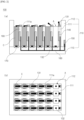
FIG. 2 is a cross-sectional view and a plan view of a cell tray according to the first exemplary embodiment of the present invention. -
FIG. 3 shows a hinge member and a first lead connector included in the cell tray according to the first exemplary embodiment of the present invention. -
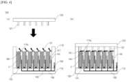
FIG. 4 shows the configuration of a tray body and a tray top included in the cell tray according to the first exemplary embodiment of the present invention. -
FIG. 5 shows the hinge member and the first lead connector included in the cell tray according to the second exemplary embodiment of the present invention. -
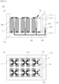
FIG. 6 is a cross-sectional view and a plan view of a cell tray according to the second exemplary embodiment of the present invention. - Hereinafter, a detailed configuration of the present invention will be described in detail with reference to the accompanying drawings and various embodiments. The embodiments described below are shown by way of an example to aid understanding of the present invention, and the accompanying drawings are not drawn to scale in order to aid understanding of the present invention, and the dimensions of some of the components may be exaggerated.
- Since the present invention can make various changes and can take various forms, specific embodiments are illustrated in the drawings and described in detail in the specification. However, it is not intended to limit the present invention to a specific disclosed form, and it should be understood to include all modifications, equivalents, or substitutes included in the spirit and technical scope of the present invention.
- The present invention relates to a
cell tray 100 accommodating multiple cylindrical cells C each in which two electrode tabs are respectively formed on the upper part and the lower part. - The
cell tray 100 of the present invention includes: atray body 110 that accommodates multiple cylindrical cells C, has an open upper part, and has a partitioningwall 111 diving the internal space so that multiple cylindrical cells C are each accommodated between thepartition walls 111, afirst connector 131 pivotably installed on an upper part of thepartition wall 111 and pivoting toward the upper electrode tab so as to come into contact with the upper electrode tab of the cylindrical cell C accommodated between thepartition walls 111, asecond connector 132 installed in the tray body between thepartition walls 111 and comes into contact with the lower electrode tab of the cylindrical cell accommodated between thepartition walls 111, and an electricalcharacteristic measuring device 140 that is electrically connected to thefirst connector 131 and thesecond connector 132 to measure the electrical characteristics of the cylindrical cell C. - The
tray body 110 includes abottom plate 113 on which the cylindrical cells C are settled, a lattice-type partition wall 111 in which the cylindrical cells C are accommodated and which is installed on thebottom plate 113, and anouter frame 112 surrounding thepartition wall 111. -
FIG. 2 through FIG. 4 show the configuration of thecell tray 100 according to the first exemplary embodiment of the present invention, andFIG. 5 through FIG. 6 show the configuration of thecell tray 100 according to the second exemplary embodiment of the present invention. - Hereinafter, the configuration and function of the
cell tray 100 of the present invention will be described with reference to the drawings. - The basic structure of the
cell tray 100 of the present invention is almost the same as that ofFIG. 1 referred to in the background art. However, additional configurations have been added to thecell tray 100 of the present invention to continuously monitor the trend of the electrical characteristics of the cylindrical cells C accommodated in the existing structure. - Specifically, the
cell tray 100 of the present invention includes connectors that can be electrically connected by being in contact with the electrode tabs formed on the top and bottom of the cell in order to determine the electrical characteristics of each of the accommodated cylindrical cells C. It will be described with reference toFIG. 2 through FIG. 4 . -
FIG. 2 is a cross-sectional view (FIG. 2(a) ) and a plan view (FIG. 2(b) ) of thecell tray 100 according to the first exemplary embodiment of the present invention. - Referring to
FIG. 2 , thecell tray 100 of the present invention is composed of atray body 110 including apartition wall 111 formed so that multiple cylindrical cells C can be accommodated separately, anouter frame 112 that surrounds and supports the side surface so as to surround all the cylindrical cells C accommodated in the accommodating part A formed by thepartition wall 111, and abottom plate 113 coupled to the lower part of thepartition wall 111 and theouter frame 112 to support the lower part of the accommodated cylindrical cells C. - The
tray body 110 of the present invention includes thepartition wall 111 forming the accommodating part A in which the cylindrical cells C are accommodated. - The
partition wall 111 is designed in a lattice shape so that the cylindrical cells C can be separately accommodated in thetray body 110 one by one, and includes multiple accommodating parts A formed by the lattice structure. - As illustrated in
FIG. 2(b) , thepartition wall 111 is designed in a lattice shape, and thepartition wall 111 supports the side part of the cylindrical cell C. accommodated in the accommodating part A. If necessary, some of the side surfaces of some cylindrical cells C accommodated in the outermost part may be supported by theouter frame 112. - The
partition wall 111 may further include ahinge frame 111a that can be coupled to afirst connector 131 to be described later. Specifically, thehinge frame 111a may be installed on the upper part of thepartition wall 111. - The
hinge frame 111a may be hinged to multiplefirst connectors 131 that rotate toward the upper electrode tabs of the cylindrical cells C located in front and rear, left and right, or front, rear, left, and right of thepartition wall 111. - The
hinge frame 111a will be discussed again later when describing thefirst connector 131 with reference toFIG. 3 and the like. - The
tray body 110 of the present invention includes anouter frame 112 surrounding thepartition wall 111. - The
outer frame 112 supports thepartition wall 111 and the accommodated cylindrical cells C in a shape of surrounding them entirely, and serves to protect the cylindrical cells C from the outside. - The height of the
outer frame 112 may be higher than the height of thepartition wall 111, and the outer frame may be preferably formed higher than the height of the partition wall by a height exceeding the rotation radius of the first connector. - The
tray body 110 of the present invention includes abottom plate 113 on which the cylindrical cells C are settled. - The
bottom plate 113 is coupled to the lower surfaces of thepartition wall 111 and theouter frame 112 and serves to support thepartition wall 111 and theouter frame 112 from below. In addition, thebottom plate 113 supports the lower part of the accommodated cylindrical cells C. - The
partition wall 111, theouter frame 112, and thebottom plate 113 may be designed as an integral type, or may be designed as a separate type if necessary, and the present invention is not particularly limited thereto. - The
cell tray 100 of the present invention includes connectors electrically connected to electrode tabs formed on both sides of the accommodated cylindrical cells C. The connectors may be made of an electrically conductive metal material, such as copper. Specifically, the connectors include afirst connector 131 installed on the upper part of thepartition wall 111 and asecond connector 132 installed on thebottom plate 113. - The
first connector 131 is installed on the upper part of thepartition wall 111 and contacts the upper electrode tab of the cylindrical cell C. Specifically, thefirst connector 131 is formed by being hinged to the upper part of thepartition wall 111. - The
first connector 131 may have a hinge shaft hinged to thehinge frame 111a. Specifically, it can be seen that thefirst connector 131 is hinged to thehinge frame 111a located on the upper part of thepartition wall 111, and that the hinge rotates starting from thehinge shaft 130a. The hinge rotation of thefirst connector 131 as described above is to avoid interfering with the entry and exit of the cylindrical cell C to the accommodating part A. - When the
first connector 131 hinge rotates upward starting from thehinge shaft 130a, it opens the entrance of the accommodating part A and allows entry and exit of the cylindrical cell C, but when thefirst connector 131 hinge rotates downward starting from thehinge shaft 130a, thefirst connector 131 structurally blocks the entrance of the accommodating part A, making it impossible for the cylindrical cell C to enter and exit. Although not shown in the drawing, if thefirst connector 131 hinges downward when the cylindrical cell C is accommodated in thecell tray 100, the upper electrode tab of the cylindrical cell C and the front end of thefirst connector 131 come into contact so that electrical connection becomes possible. Conversely, if thefirst connector 131 hinges upward, thefirst connector 131 gets separated from the upper electrode tab of the cylindrical cell C, making electrical connection impossible. -
FIG. 3 shows thehinge frame 111a and thefirst connector 131 included in thecell tray 100 according to the first exemplary embodiment of the present invention. - Referring to
FIG. 3 , it can be seen that thehinge shaft 130a is formed on the rear end of both ends of thefirst connector 131, and that the front end has a shape protruding downward. The front end of thefirst connector 131 protrudes downward in order to effectively contact the electrode tab of the cylindrical cell C. However, the shape of thefirst connector 131 is not limited by the drawing, and even if the front end does not protrude downward, it is sufficient enough if it is in a shape that allows contact with the upper electrode tab of the cylindrical cell C. - The
hinge frame 111a may include a connector insertion hole, which is a space where thefirst connector 131 is inserted. In addition, thehinge frame 111a may further include agroove 111a capable of engaging with thehinge shaft 130a of thefirst connector 131 when thefirst connector 131 is inserted into the connector insertion hole. - However, the shape of the
hinge frame 111a does not need to be limited byFIG. 3 , and any shape is possible as long as thefirst connector 131 is hinged at the upper part of thepartition wall 111 and as long as it has a structure that can hinge rotate thefirst connector 131 so as not to interfere with the entry and exit of the cylindrical cell C. - When the first connector hinge rotates downward starting from the
hinge shaft 130a, it comes into contact with the upper electrode tab of the accommodated cylindrical cell C, enabling electrical connection, and when thefirst connector 131 hinge rotates upward starting from thehinge shaft 130a, the electrical connection is lost. - The
hinge frame 111a of the present invention maybe hinged with at least onefirst connector 131. Thehinge frame 111a to which multiplefirst connectors 131 are connected will be discussed again later in the second embodiment of the present invention. - The
second connector 132 is installed on thebottom plate 113 and contacts the lower part of the cylindrical cell C. - The
second connecter 132 may be on top of thebottom plate 113. Specifically, since thesecond connector 132 needs to make electrical contact with the lower electrode tab of the cylindrical cell C accommodated in the accommodating part A, it is placed on top of thebottom plate 113 corresponding to the position of the accommodating part A. - The
second connector 132 may protrude from thebottom plate 113, or it may be formed by being recessed into thebottom plate 113, and this will not be particularly limited to the present invention. However, it is sufficient enough to have a structure capable of being completely electrically connected to an electrode tab located in the lower part of the accommodated cylindrical cell C. - The
cell tray 100 of the present invention includes an electricalcharacteristic measuring device 140 that measures the electrical characteristics of the cylindrical cell C by being electrically connected to the connector. - The electrical
characteristic measuring device 140 is electrically connected to thefirst connector 131 and thesecond connector 132 through aconducting wire 160, and can measure at least one characteristic of the current, voltage, and resistance of the cylindrical cell C that is in contact with each of the connectors. - The electrical characteristic measuring device may be installed on the
tray body 110. - Specifically, the electrical
characteristic measuring device 140 may be installed on thepartition wall 111, preferably installed in a form inserted into thepartition wall 111 so that the entry and exit of the cylindrical cell C to the accommodating part A is not hindered. - The electrical
characteristic measuring device 140 may transmit the measured characteristic value of the cylindrical cell C to the outside. Specifically, the present exemplary embodiment has awireless communication device 150 connected to the electricalcharacteristic measuring device 140 installed on thetray body 110. As thewireless communication device 150, for example, an external NFC (Near Field Communication) tag acting as a reader and an NFC pad equipped with an NFC tag capable of wireless communication can be used. Alternatively, as thewireless communication device 150, an RFID tag capable of wireless communication with an external RFID (Radio Frequency Identification) reader can be used. However, the wireless communication device and wireless communication method are not limited to the above examples, and the wireless communication device of a different type can be used as long as it can effectively transmit the characteristic value of the cylindrical cell to the outside. Suchwireless communication device 150 may transmit data transmitted from the electricalcharacteristic measuring device 140 to the outside by communicating with a receiving device outside the tray. - The
wireless communication device 150 may be installed on theouter frame 112 included in thetray body 110 or the outer side of thebottom plate 113 to effectively transmit the electrical characteristics of the cylindrical cells C accommodated in thecell tray 100 to the outside. - A plurality of the
wireless communication devices 150 corresponding to the number of cylindrical cells C may also be installed. In this case, each characteristic value may be derived from thewireless communication device 150 corresponding to each cell, and communication between thewireless communication devices 150 of each cell is also possible. Therefore, by installing a master wireless communication device 150 (e.g., a master NFC pad) that receives characteristic values from thewireless communication device 150 of each cell, the characteristic values of multiple cells can be collectively transmitted to the outside from the masterwireless communication device 150. An external receiving device, for example, can be installed on a stacker crane that transfers thebattery cell tray 100, and it is also possible to be installed on a storage rack of a warehouse where thebattery cell tray 100 is stored. - The
cell tray 100 of the present invention includes a coolingmember 170 capable of cooling the cylindrical cells C and thecell tray 100 when the accommodated cylindrical cells C generate heat. - The cooling
member 170 may preferably be a thermoelectric module or the like. - The cooling
member 170, without using a refrigerant, can be substituted for any device that includes a function capable of cooling the accommodated cylindrical cells C as much as desired. - The cooling
member 170 may be operated by receiving power from a separate power source (not shown) built into thetray body 110, or may be supplied with electricity by being electrically connected to the cylindrical cells C accommodated in thetray body 110. - The cooling
member 170 does not require a separate refrigerant, and when electricity is being supplied, one side proceeds to absorb heat, and the other side opposite to the one side proceeds to release heat. Specifically, the coolingmember 170 includes a heat absorbing part (not shown) for absorbing heat on one side, and a heat generating part (not shown) for releasing heat on the other side opposite to the one side. The coolingmember 170 is preferably installed on thebottom plate 113 so that the one side including the heat absorbing part and the other side including the heat generating part can face the accommodating part A and the outside, respectively. - As illustrated in
FIG. 2 , it is desirable to have the coolingmember 170 installed on thebottom plate 113 of thetray body 110. More specifically, thebottom plate 113 includes an accommodating groove (not shown), which is a space where the coolingmember 170 can be installed, and the coolingmember 170 may be installed by being inserted into the accommodating groove. Here, it is preferable to locate thesecond connector 132 on the coolingmember 170. This allows one side of thebottom plate 113 to come into contact with all of the accommodated cylindrical cells C, so that the heat generated from the accommodating part A can be effectively absorbed, and it is a structure that can effectively discharge the absorbed heat to the outside. - Here, it is desirable for the cooling
member 170 to have its one side that absorbs heat face the direction of the accommodating part A of thetray body 110, and have the other side that generates heat face the outward direction of thetray body 110. - The
cell tray 100 of the present invention may additionally include atray top 120 coupled to thetray body 110 while covering the opened upper part of thetray body 110 at the upper part of thetray body 110. -
FIG. 4 shows the configuration of thetray body 110 and thetray top 120 included in thecell tray 100 according to the first exemplary embodiment of the present invention. - Referring to
FIG. 4 , thecell tray 100 of the present invention may further include atray top 120 that coupled to theouter frame 112 included in thetray body 110 to cover the accommodated cylindrical cells C. - The
cell tray 100 of the present invention can not only prevent foreign substances from mixing in to thetray body 110 by having thetray top 120, but it can also serve to pressurize so that the contact of the electrode tab of thefirst connector 131 and the cylindrical cell C can be stably made. - When the
tray top 120 is coupled to theouter frame 112 at the upper part of thetray body 110, it can include an insulatingmember 121 that protrudes downward at a position corresponding to the cylindrical cells C accommodated in thetray body 110. - Referring to
FIG. 4 , it can be known that the insulatingmember 121 is preventing the electrical connection of thefirst connector 131 and the electrode tab from being disconnected by pressing the upper part of thefirst connector 131. In particular, even if thecell tray 100 receives an external shock while moving, the electrical connection of thefirst connector 131 and the electrode tab of the cylindrical cell C may be maintained due to the insulatingmember 121 of thetray top 120. - The
tray top 120 may further include the electricalcharacteristic measuring device 140 if necessary. -
FIG. 5 shows thehinge frame 111a and thefirst connector 131 included in thecell tray 100 according to the second exemplary embodiment of the present invention. - Referring to
FIG. 5 , it can be known that asingle hinge frame 111a includes four hinge coupling parts S, and that fourfirst connectors 131 are hinged to each of the hinge coupling parts S. - A
cell tray 100 structure to which the configurations of thehinge frame 111a and thefirst connector 131 are applied is shown inFIG. 6 . -
FIG. 6 is a cross-sectional view and a plan view of acell tray 100 according to the second exemplary embodiment of the present invention. - The
hinge frame 111a has four hinge coupling parts S, and fourfirst connectors 131 are each hinged to the hinge coupling parts S, and the hinge frame is installed so that the four hinge coupling parts S face the diagonal direction of the lattice space formed by thepartition walls 111 at the upper part of thepartition wall 111 at the point where thelattice partition walls 111 intersect, allowing thefirst connector 131 to rotate up and down in the diagonal direction of the lattice space. - Referring to
FIG. 6 , it can be known that thehinge frame 111a is located at the upper part of thepartition wall 111, and fourfirst connectors 131 are hinged to asingle hinge frame 111a. Thefirst connector 131, unlike thefirst connector 131 included in thecell tray 100 according to the first exemplary embodiment, is installed so as to hinge rotate toward the accommodating part A located in the diagonal direction. - That is, since it is designed to enable four electrical connections through a
single hinge frame 111a, it can be seen that thecell tray 100 according to the second exemplary embodiment can secure more internal space of thetray body 110, and that the ease of use is better improved. - As above, the present invention has been described with reference to exemplary embodiments, but it should be understood by those killed in the art or those of ordinary skill in the art that the present invention can be variously modified and changed without departing from the spirit and technical scope of the present invention described in the accompanying claims.
-
- 10:
- (CONVENTIONAL) MAIN BODY
- 11:
- (CONVENTIONAL) BATTERY ACCOMMODATING PART
- 20:
- (CONVENTIONAL) COVER
- 30:
- (CONVENTIONAL) CYLINDRICAL CELL
- 100:
- CELL TRAY
- 110:
- TRAY BODY
- 111:
- PARTITION WALL
- 111a:
- HINGE FRAME
- 111a1:
- GROOVE
- 112:
- OUTER FRAME
- 113:
- BOTTOM PLATE
- 120:
- TRAY TOP
- 121:
- INSULATING MEMBER
- 130a:
- HINGE SHAFT
- 131:
- FIRST CONNECTOR
- 132:
- SECOND CONNECTOR
- 140:
- ELECTRICAL CHARACTERISTIC MEASURING DEVICE
- 150:
- WIRELESS COMMUNICATION DEVICE
- 160:
- CONDUCTING WIRE
- 170:
- COOLING MEMBER
- C:
- CYLINDRICAL CELL
- A:
- ACCOMMODATING PART
- S:
- HINGE COUPLING PART
Claims (15)
- A cell tray, comprising:a tray body in which upper part is open and has a partitioning wall dividing the internal space so that multiple cylindrical cells are each accommodated between the partition walls;a first connector pivotably installed on an upper part of the partition wall, and pivoting toward the upper electrode tab so as to come into contact with the upper electrode tab of the cylindrical cell accommodated between the partition walls;a second connector installed in the tray body between the partition walls and comes into contact with the lower electrode tab of the cylindrical cell accommodated between the partition walls; andan electrical characteristic measuring device that is electrically connected to the first connector and the second connector to measure the electrical characteristics of the cylindrical cell.
- The cell tray of claim 1, wherein
the partition wall is formed in a lattice shape. - The cell tray of claim 2, wherein
the tray body comprises a bottom plate forming the lower part of the tray body, a lattice-type partition wall installed on the bottom plate, and an outer frame surrounding the lattice-type partition wall and coupled to the bottom plate or integrally formed with the bottom plate. - The cell tray of claim 3, wherein
the outer frame is formed higher than the height of the partition wall, with a height exceeding the rotation radius of the first connector. - The cell tray of claim 1, whereina hinge frame is installed on the upper part of the partition wall,and the first connector has a hinge shaft hinged to the hinge frame.
- The cell tray of claim 1, wherein
the electrical characteristic measuring device measures at least one of the characteristics of resistance, voltage, and current of the accommodated cylindrical cell. - The cell tray of claim 1, wherein
a wireless communication device connected to the electrical characteristic measuring device and capable of transmitting the electrical characteristic values of the cylindrical cell measured by the electrical characteristic measuring device to the outside is installed on the tray body. - The cell tray of claim 3, wherein
a cooling member for cooling the cylindrical cell is installed on the bottom plate of the tray body. - The cell tray of claim 8, wherein
a cooling member accommodating groove is formed in the bottom plate so that the cooling member is installed in the cooling member accommodating groove, and the second connector is installed on the cooling member. - The cell tray of claim 1, wherein
the cooling member is a thermoelectric module. - The cell tray of claim 1,
further comprising a tray top coupled to the tray body while covering the opened upper part of the tray body. - The cell tray of claim 1, wherein
the tray top comprises an insulating member protruding downward at a position corresponding to the cylindrical cell accommodated between the partition walls. - The cell tray of claim 11, wherein
the electrical characteristic measuring device is installed either on the tray body or on the tray top. - The cell tray of claim 5, wherein
the hinge frame is hinged to multiple first connectors rotating toward the upper electrode tab of the cylindrical cell located in front and rear, left and right, or front, rear, left, and right of the partition wall. - The cell tray of claim 14, whereinthe partition wall is formed in a lattice shape;the hinge frame has four hinge coupling parts, and four first connectors are each hinged to the hinge coupling parts; andthe hinge frame is installed so that the four hinge coupling parts face the diagonal direction of the lattice space formed by the partition walls at the upper part of the partition wall at the point where the lattice partition walls intersect, allowing the first connector to rotate up and down in the diagonal direction of the lattice space.
Applications Claiming Priority (2)
| Application Number | Priority Date | Filing Date | Title |
|---|---|---|---|
| KR1020210143958A KR102815177B1 (en) | 2021-10-26 | 2021-10-26 | Cell tray |
| PCT/KR2022/015883 WO2023075269A1 (en) | 2021-10-26 | 2022-10-18 | Cell tray |
Publications (2)
| Publication Number | Publication Date |
|---|---|
| EP4246685A1 true EP4246685A1 (en) | 2023-09-20 |
| EP4246685A4 EP4246685A4 (en) | 2025-06-25 |
Family
ID=86158186
Family Applications (1)
| Application Number | Title | Priority Date | Filing Date |
|---|---|---|---|
| EP22887465.7A Pending EP4246685A4 (en) | 2021-10-26 | 2022-10-18 | CELL SHELL |
Country Status (6)
| Country | Link |
|---|---|
| US (1) | US20240047811A1 (en) |
| EP (1) | EP4246685A4 (en) |
| JP (1) | JP7552912B2 (en) |
| KR (1) | KR102815177B1 (en) |
| CN (1) | CN116802908A (en) |
| WO (1) | WO2023075269A1 (en) |
Family Cites Families (24)
| Publication number | Priority date | Publication date | Assignee | Title |
|---|---|---|---|---|
| JPH11271409A (en) * | 1998-03-23 | 1999-10-08 | Sony Corp | Battery tray and battery test method |
| FR2916306B1 (en) | 2007-05-15 | 2009-07-17 | Batscap Sa | MODULE FOR ELECTRIC ENERGY STORAGE ASSEMBLIES FOR DETECTING THE AGING OF THESE ASSEMBLIES. |
| FR2924857B1 (en) * | 2007-12-06 | 2014-06-06 | Valeo Equip Electr Moteur | ELECTRICAL SUPPLY DEVICE COMPRISING A RECEPTION UNIT FOR ULTRA CAPACITY STORAGE UNITS |
| KR101986384B1 (en) * | 2013-01-07 | 2019-06-05 | 에스케이이노베이션 주식회사 | Sensing assembly for secondary battery and Secondary Battery having the sensing assembly |
| KR102108575B1 (en) * | 2013-08-09 | 2020-05-07 | 현대모비스 주식회사 | Cell frame structure |
| CN103985831B (en) * | 2014-05-16 | 2016-03-09 | 力帆实业(集团)股份有限公司 | A kind of thermal-control battery case and temperature control method thereof |
| KR101521267B1 (en) * | 2014-10-28 | 2015-05-20 | 주식회사 에스엘텍 | Test tray for secondary cell |
| GB2533277B (en) * | 2014-12-08 | 2017-12-06 | Intelligent Energy Ltd | Fuel cell assembly and associated method of operation |
| US9735414B2 (en) * | 2015-08-11 | 2017-08-15 | Atieva, Inc. | Current distribution system for a battery assembly utilizing non-overlapping bus bars |
| JP6694687B2 (en) * | 2015-09-30 | 2020-05-20 | Fdk株式会社 | Tab for mounting protective element of assembled battery and assembled battery |
| FR3042093B1 (en) * | 2015-10-05 | 2017-10-06 | Blue Solutions | ELECTRIC ENERGY STORAGE MODULE AND METHOD FOR MANUFACTURING THE SAME |
| KR102116384B1 (en) * | 2017-01-11 | 2020-05-28 | 주식회사 엘지화학 | Tray for Activating Battery Cell Comprising Elastic Member |
| KR102033003B1 (en) * | 2017-02-28 | 2019-10-16 | 주식회사 유라코퍼레이션 | Frame assembly |
| US11043823B2 (en) | 2017-04-06 | 2021-06-22 | Tesla, Inc. | System and method for facilitating conditioning and testing of rechargeable battery cells |
| US10886513B2 (en) * | 2017-05-16 | 2021-01-05 | Shape Corp. | Vehicle battery tray having tub-based integration |
| US20190081372A1 (en) * | 2017-09-12 | 2019-03-14 | Sf Motors, Inc. | Modular battery system to provide power to electric vehicles |
| JP2019117753A (en) | 2017-12-27 | 2019-07-18 | 日立化成株式会社 | Storage battery system and power system |
| KR102387769B1 (en) | 2018-02-06 | 2022-04-19 | 주식회사 엘지에너지솔루션 | Battery Tray with Improved Safety |
| FR3085794B1 (en) | 2018-09-12 | 2020-11-13 | Commissariat Energie Atomique | ELECTROCHEMICAL ACCUMULATOR BATTERY PACK INCLUDING PASSIVE MAGNETIC DISCONNECTION DEVICES BETWEEN THE ACCUMULATORS AND BUSBARS, AND IF ANY PASSIVE SHUNT OF ONE OR MORE ACCUMULATORS IN THE EVENT OF A FAILURE OF ONE OF THEM |
| WO2020215284A1 (en) * | 2019-04-25 | 2020-10-29 | 海能达通信股份有限公司 | Electronic device |
| CN210129536U (en) * | 2019-07-20 | 2020-03-06 | 马根英 | Battery fixing and heat dissipating structure of new energy electric vehicle |
| KR102913678B1 (en) * | 2019-07-25 | 2026-01-15 | 삼성에스디아이 주식회사 | Battery pack |
| KR102849577B1 (en) * | 2019-08-27 | 2025-08-21 | 주식회사 엘지에너지솔루션 | Battery Pack Having Cell Frame |
| KR102340454B1 (en) | 2020-05-20 | 2021-12-20 | 주식회사 티케이씨 | Apparatus For Processing Plate |
-
2021
- 2021-10-26 KR KR1020210143958A patent/KR102815177B1/en active Active
-
2022
- 2022-10-18 EP EP22887465.7A patent/EP4246685A4/en active Pending
- 2022-10-18 US US18/269,222 patent/US20240047811A1/en active Pending
- 2022-10-18 CN CN202280008409.0A patent/CN116802908A/en active Pending
- 2022-10-18 WO PCT/KR2022/015883 patent/WO2023075269A1/en not_active Ceased
- 2022-10-18 JP JP2023535530A patent/JP7552912B2/en active Active
Also Published As
| Publication number | Publication date |
|---|---|
| JP2024500669A (en) | 2024-01-10 |
| WO2023075269A1 (en) | 2023-05-04 |
| KR102815177B1 (en) | 2025-05-30 |
| KR20230059610A (en) | 2023-05-03 |
| EP4246685A4 (en) | 2025-06-25 |
| JP7552912B2 (en) | 2024-09-18 |
| US20240047811A1 (en) | 2024-02-08 |
| CN116802908A (en) | 2023-09-22 |
Similar Documents
| Publication | Publication Date | Title |
|---|---|---|
| US10461288B2 (en) | Battery module and battery pack including same | |
| US9331324B2 (en) | Connector assembly and battery pack having the same | |
| TWI695533B (en) | Battery module and battery pack including the same | |
| KR100954029B1 (en) | Protective circuit module for secondary battery and secondary battery using same | |
| CN100477364C (en) | Secondary battery | |
| KR101438439B1 (en) | Battery Cell of Novel Embedded Type Structure | |
| KR20170050508A (en) | Battery module and battery pack including the same | |
| US20250096380A1 (en) | Battery cell with serpentine tab | |
| EP3550635B1 (en) | Battery module and battery pack including the same | |
| US12482872B2 (en) | Battery module and battery pack including the same | |
| US20150050538A1 (en) | Energy storage apparatus | |
| US8343653B2 (en) | Secondary battery | |
| US9252460B2 (en) | Secondary battery | |
| KR20150109726A (en) | Battery Module Assembly | |
| US20090033286A1 (en) | Cell and Supercapacitor Battery Pack | |
| CN107615518B (en) | Battery module and battery pack including the same | |
| KR20140099846A (en) | Battery Cell of Novel Embedded Type Structure | |
| US20240047811A1 (en) | Cell tray | |
| JP2002216726A (en) | Battery and battery element storage case | |
| US20150287972A1 (en) | Rechargeable battery having lead tab | |
| KR102876794B1 (en) | Tray for unidirectional battery cells | |
| KR100853620B1 (en) | Battery module spacer | |
| CN120108978A (en) | Power relay assembly and battery system including the same |
Legal Events
| Date | Code | Title | Description |
|---|---|---|---|
| STAA | Information on the status of an ep patent application or granted ep patent |
Free format text: STATUS: THE INTERNATIONAL PUBLICATION HAS BEEN MADE |
|
| PUAI | Public reference made under article 153(3) epc to a published international application that has entered the european phase |
Free format text: ORIGINAL CODE: 0009012 |
|
| STAA | Information on the status of an ep patent application or granted ep patent |
Free format text: STATUS: REQUEST FOR EXAMINATION WAS MADE |
|
| 17P | Request for examination filed |
Effective date: 20230613 |
|
| AK | Designated contracting states |
Kind code of ref document: A1 Designated state(s): AL AT BE BG CH CY CZ DE DK EE ES FI FR GB GR HR HU IE IS IT LI LT LU LV MC ME MK MT NL NO PL PT RO RS SE SI SK SM TR |
|
| DAV | Request for validation of the european patent (deleted) | ||
| DAX | Request for extension of the european patent (deleted) | ||
| A4 | Supplementary search report drawn up and despatched |
Effective date: 20250527 |
|
| RIC1 | Information provided on ipc code assigned before grant |
Ipc: H01M 10/613 20140101ALI20250521BHEP Ipc: H01M 10/6572 20140101ALI20250521BHEP Ipc: H01M 10/42 20060101ALI20250521BHEP Ipc: H01M 10/48 20060101ALI20250521BHEP Ipc: H01M 50/502 20210101ALI20250521BHEP Ipc: H01M 50/24 20210101ALI20250521BHEP Ipc: H01M 50/291 20210101ALI20250521BHEP Ipc: H01M 50/213 20210101AFI20250521BHEP |
|
| STAA | Information on the status of an ep patent application or granted ep patent |
Free format text: STATUS: EXAMINATION IS IN PROGRESS |
|
| 17Q | First examination report despatched |
Effective date: 20251107 |
|
| GRAP | Despatch of communication of intention to grant a patent |
Free format text: ORIGINAL CODE: EPIDOSNIGR1 |
|
| STAA | Information on the status of an ep patent application or granted ep patent |
Free format text: STATUS: GRANT OF PATENT IS INTENDED |
|
| INTG | Intention to grant announced |
Effective date: 20260303 |