EP4246502A2 - Mobiles endgerät - Google Patents
Mobiles endgerät Download PDFInfo
- Publication number
- EP4246502A2 EP4246502A2 EP23185193.2A EP23185193A EP4246502A2 EP 4246502 A2 EP4246502 A2 EP 4246502A2 EP 23185193 A EP23185193 A EP 23185193A EP 4246502 A2 EP4246502 A2 EP 4246502A2
- Authority
- EP
- European Patent Office
- Prior art keywords
- frame
- mobile terminal
- display unit
- side portion
- slide
- Prior art date
- Legal status (The legal status is an assumption and is not a legal conclusion. Google has not performed a legal analysis and makes no representation as to the accuracy of the status listed.)
- Granted
Links
Images


Classifications
-
- H—ELECTRICITY
- H04—ELECTRIC COMMUNICATION TECHNIQUE
- H04M—TELEPHONIC COMMUNICATION
- H04M1/00—Substation equipment, e.g. for use by subscribers
- H04M1/02—Constructional features of telephone sets
- H04M1/0202—Portable telephone sets, e.g. cordless phones, mobile phones or bar type handsets
- H04M1/0206—Portable telephones comprising a plurality of mechanically joined movable body parts, e.g. hinged housings
- H04M1/0208—Portable telephones comprising a plurality of mechanically joined movable body parts, e.g. hinged housings characterized by the relative motions of the body parts
- H04M1/0235—Slidable or telescopic telephones, i.e. with a relative translation movement of the body parts; Telephones using a combination of translation and other relative motions of the body parts
- H04M1/0237—Sliding mechanism with one degree of freedom
-
- G—PHYSICS
- G06—COMPUTING OR CALCULATING; COUNTING
- G06F—ELECTRIC DIGITAL DATA PROCESSING
- G06F1/00—Details not covered by groups G06F3/00 - G06F13/00 and G06F21/00
- G06F1/16—Constructional details or arrangements
- G06F1/1613—Constructional details or arrangements for portable computers
- G06F1/1633—Constructional details or arrangements of portable computers not specific to the type of enclosures covered by groups G06F1/1615 - G06F1/1626
- G06F1/1637—Details related to the display arrangement, including those related to the mounting of the display in the housing
- G06F1/1652—Details related to the display arrangement, including those related to the mounting of the display in the housing the display being flexible, e.g. mimicking a sheet of paper, or rollable
-
- G—PHYSICS
- G06—COMPUTING OR CALCULATING; COUNTING
- G06F—ELECTRIC DIGITAL DATA PROCESSING
- G06F1/00—Details not covered by groups G06F3/00 - G06F13/00 and G06F21/00
- G06F1/16—Constructional details or arrangements
- G06F1/1613—Constructional details or arrangements for portable computers
- G06F1/1615—Constructional details or arrangements for portable computers with several enclosures having relative motions, each enclosure supporting at least one I/O or computing function
- G06F1/1624—Constructional details or arrangements for portable computers with several enclosures having relative motions, each enclosure supporting at least one I/O or computing function with sliding enclosures, e.g. sliding keyboard or display
-
- G—PHYSICS
- G06—COMPUTING OR CALCULATING; COUNTING
- G06F—ELECTRIC DIGITAL DATA PROCESSING
- G06F1/00—Details not covered by groups G06F3/00 - G06F13/00 and G06F21/00
- G06F1/16—Constructional details or arrangements
- G06F1/1613—Constructional details or arrangements for portable computers
- G06F1/1633—Constructional details or arrangements of portable computers not specific to the type of enclosures covered by groups G06F1/1615 - G06F1/1626
- G06F1/1675—Miscellaneous details related to the relative movement between the different enclosures or enclosure parts
- G06F1/1681—Details related solely to hinges
-
- H—ELECTRICITY
- H04—ELECTRIC COMMUNICATION TECHNIQUE
- H04M—TELEPHONIC COMMUNICATION
- H04M1/00—Substation equipment, e.g. for use by subscribers
- H04M1/02—Constructional features of telephone sets
- H04M1/0202—Portable telephone sets, e.g. cordless phones, mobile phones or bar type handsets
- H04M1/026—Details of the structure or mounting of specific components
- H04M1/0266—Details of the structure or mounting of specific components for a display module assembly
- H04M1/0268—Details of the structure or mounting of specific components for a display module assembly including a flexible display panel
-
- H—ELECTRICITY
- H05—ELECTRIC TECHNIQUES NOT OTHERWISE PROVIDED FOR
- H05K—PRINTED CIRCUITS; CASINGS OR CONSTRUCTIONAL DETAILS OF ELECTRIC APPARATUS; MANUFACTURE OF ASSEMBLAGES OF ELECTRICAL COMPONENTS
- H05K5/00—Casings, cabinets or drawers for electric apparatus
- H05K5/0086—Casings, cabinets or drawers for electric apparatus portable, e.g. battery operated apparatus
-
- H—ELECTRICITY
- H05—ELECTRIC TECHNIQUES NOT OTHERWISE PROVIDED FOR
- H05K—PRINTED CIRCUITS; CASINGS OR CONSTRUCTIONAL DETAILS OF ELECTRIC APPARATUS; MANUFACTURE OF ASSEMBLAGES OF ELECTRICAL COMPONENTS
- H05K5/00—Casings, cabinets or drawers for electric apparatus
- H05K5/02—Details
- H05K5/0217—Mechanical details of casings
-
- G—PHYSICS
- G09—EDUCATION; CRYPTOGRAPHY; DISPLAY; ADVERTISING; SEALS
- G09F—DISPLAYING; ADVERTISING; SIGNS; LABELS OR NAME-PLATES; SEALS
- G09F9/00—Indicating arrangements for variable information in which the information is built-up on a support by selection or combination of individual elements
- G09F9/30—Indicating arrangements for variable information in which the information is built-up on a support by selection or combination of individual elements in which the desired character or characters are formed by combining individual elements
- G09F9/301—Indicating arrangements for variable information in which the information is built-up on a support by selection or combination of individual elements in which the desired character or characters are formed by combining individual elements flexible foldable or roll-able electronic displays, e.g. thin LCD, OLED
-
- H—ELECTRICITY
- H04—ELECTRIC COMMUNICATION TECHNIQUE
- H04M—TELEPHONIC COMMUNICATION
- H04M2201/00—Electronic components, circuits, software, systems or apparatus used in telephone systems
- H04M2201/08—Magnetic elements
Definitions
- a display device is a device having a function of receiving, processing, and displaying a video that a user may watch. For example, the display device receives a broadcast selected by the user from broadcast signals transmitted from a broadcasting station, separates a video signal from the received signals, and displays the separated video signal on a display.
- the size of a mobile terminal can be varied using the deformable nature of the flexible display.
- changing the size of the mobile terminal should be stably performed, and there is a need for a structure to support the extended display unit to maintain a flat state of the display unit.
- One purpose of the present disclosure is to provide a mobile terminal that may improve durability of a flexible display unit by not restricting a point where the flexible display unit is bent to a specific position.
- Another purpose of the present disclosure is to provide a mobile terminal including a support structure of a flexible display unit that may stably support the flexible display unit when the flexible display unit is extended.
- a mobile terminal may include a first frame, a second frame configured to slidably move from the first frame in a first direction or a second direction, the second direction being opposite to the first direction, a slide frame configured to move with respect to the second frame in the first direction or the second direction, a flexible display including a first region coupled to the first frame, a second region coupled to the slide frame, and a third region disposed between the first region and the second region, the third region being bent in a manner of surrounding the second frame, and a rolling plate attached to a rear surface of the flexible display, wherein the second frame may include a side portion positioned at an end thereof facing in a third direction perpendicular to the first direction, and a slide rail formed on the side portion, wherein the rolling plate may include a plurality of support bars extending in the third direction perpendicular to the first direction and arranged side by side in the first direction, and a slide
- the slide hook may have a cylindrical shape.
- a width of the first expanded side portion in the first direction may be narrowed as the first expanded side portion extends away from the flexible display.
- the expanded side portion may further include a second expanded side portion forming a step with respect to the first expanded side portion, wherein the second expanded side portion may be disposed to overlap the first expanded side portion of a neighboring support bar among the support bars.
- the side portion of the second frame may include an opening positioned on a front side, wherein a width of the opening may correspond to a size of the second expanded side portion.
- An end portion of the expanded side portion facing the flexible display may include a curved surface.
- the mobile terminal may further include a roller coupled to the second frame to be rotatable about a rotation axis extending in the third direction perpendicular to the first direction, wherein the third region may be bent in a manner of surrounding the roller, wherein each of the support bars may include a curved surface corresponding to a curvature of the roller.
- the slide rail may include a first horizontal portion positioned adjacent to a rear of the second frame, a second horizontal portion positioned in front of the second frame and arranged parallel to the first horizontal portion, and a curved portion connecting ends of the first horizontal portion and the second horizontal portion facing in the first direction.
- the side portion of the second frame may include an opening positioned on a front side of the first horizontal portion, wherein, when the second frame is moved in the first direction to switch from a first state to a second state, an end of the rolling plate facing in the third direction may be exposed to an outside through the opening.
- the mobile terminal may further include a rolling ball inserted into the side portion of the second frame, wherein, when the second frame is moved in the first direction or the second direction, the rolling ball may rotate in contact with the first frame.
- the rolling plate may further include a rolling sheet having one surface coupled to the flexible display and an opposite surface coupled to the support bars.
- the rolling sheet may include a superelastic metal sheet.
- the grooves may be positioned between the support bars.
- the mobile terminal may further include a flexible connector configured to connect the support bars.
- the mobile terminal of the present disclosure may allow the size of the screen to be adjusted as needed, thereby satisfying both portability and usability.
- the mobile terminal of the present disclosure may reduce the damage caused by a concentrated stress on the display unit because the stress is not concentrated at a specific point.
- the display unit may be maintained in a flat state by preventing the display unit from being separated during movement of the second frame.
- a singular representation may include a plural representation unless it represents a definitely different meaning from the context.
- FIG. 1 is a block diagram of a mobile terminal in accordance with the present disclosure.
- the mobile terminal 100 is shown having components such as a wireless communication unit 110, an input unit 120, a sensing unit 140, an output unit 150, an interface unit 160, a memory 170, a controller 180, and a power supply unit 190.
- a wireless communication unit 110 configured with several commonly implemented components. It is understood that implementing all of the illustrated components is not a requirement, and that greater or fewer components may alternatively be implemented.
- the wireless communication unit 110 typically includes one or more modules which permit communications such as wireless communications between the mobile terminal 100 and a wireless communication system, communications between the mobile terminal 100 and another mobile terminal, communications between the mobile terminal 100 and an external server. Further, the wireless communication unit 110 typically includes one or more modules which connect the mobile terminal 100 to one or more networks.
- the wireless communication unit 110 includes one or more of a broadcast receiving module 111, a mobile communication module 112, a wireless Internet module 113, a short-range communication module 114, and a location information module 115.
- the broadcast receiving module 111 is typically configured to receive a broadcast signal and/or broadcast associated information from an external broadcast managing entity via a broadcast channel.
- the broadcast channel may include a satellite channel, a terrestrial channel, or both.
- two or more broadcast receiving modules 111 may be utilized to facilitate simultaneously receiving of two or more broadcast channels, or to support switching among broadcast channels.
- the mobile communication module 112 can transmit and/or receive wireless signals to and from one or more network entities.
- a network entity include a base station, an external mobile terminal, a server, and the like.
- Such network entities form part of a mobile communication network, which is constructed according to technical standards or communication methods for mobile communications (for example, Global System for Mobile Communication (GSM), Code Division Multi Access (CDMA), CDMA2000 (Code Division Multi Access 2000), EV-DO (Enhanced Voice-Data Optimized or Enhanced Voice-Data Only), Wideband CDMA (WCDMA), High Speed Downlink Packet access (HSDPA), HSUPA (High Speed Uplink Packet Access), Long Term Evolution (LTE) , LTE-A (Long Term Evolution-Advanced), and the like).
- GSM Global System for Mobile Communication
- CDMA Code Division Multi Access
- CDMA2000 Code Division Multi Access 2000
- EV-DO Enhanced Voice-Data Optimized or Enhanced Voice-Data Only
- WCDMA Wideband CDMA
- HSDPA High Speed
- Examples of wireless signals transmitted and/or received via the mobile communication module 112 include audio call signals, video (telephony) call signals, or various formats of data to support communication of text and multimedia messages.
- the wireless Internet module 113 is configured to facilitate wireless Internet access. This module may be internally or externally coupled to the mobile terminal 100. The wireless Internet module 113 may transmit and/or receive wireless signals via communication networks according to wireless Internet technologies.
- wireless Internet access examples include Wireless LAN (WLAN), Wireless Fidelity (Wi-Fi), Wi-Fi Direct, Digital Living Network Alliance (DLNA), Wireless Broadband (WiBro), Worldwide Interoperability for Microwave Access (WiMAX), High Speed Downlink Packet Access (HSDPA), HSUPA(High Speed Uplink Packet Access), Long Term Evolution (LTE), LTE-A (Long Term Evolution-Advanced), and the like.
- the wireless Internet module 113 may transmit/receive data according to one or more of such wireless Internet technologies, and other Internet technologies as well.
- the wireless Internet module 113 when the wireless Internet access is implemented according to, for example, WiBro, HSDPA,HSUPA, GSM, CDMA, WCDMA, LTE, LTE-A and the like, as part of a mobile communication network, the wireless Internet module 113 performs such wireless Internet access. As such, the Internet module 113 may cooperate with, or function as, the mobile communication module 112.
- the short-range communication module 114 is configured to facilitate short-range communications. Suitable technologies for implementing such short-range communications include BLUETOOTHTM, Radio Frequency IDentification (RFID), Infrared Data Association (IrDA), Ultra-WideBand (UWB), ZigBee, Near Field Communication (NFC), Wireless-Fidelity (Wi-Fi), Wi-Fi Direct, Wireless USB(Wireless Universal Serial Bus), and the like.
- the short-range communication module 114 in general supports wireless communications between the mobile terminal 100 and a wireless communication system, communications between the mobile terminal 100 and another mobile terminal 100, or communications between the mobile terminal and a network where another mobile terminal 100 (or an external server) is located, via wireless area networks.
- One example of the wireless area networks is a wireless personal area networks.
- the location information module 115 is generally configured to detect, calculate, derive or otherwise identify a position of the mobile terminal.
- the location information module 115 includes a Global Position System (GPS) module, a Wi-Fi module, or both. If desired, the location information module 115 may alternatively or additionally function with any of the other modules of the wireless communication unit 110 to obtain data related to the position of the mobile terminal.
- GPS Global Position System
- a position of the mobile terminal may be acquired using a signal sent from a GPS satellite.
- Wi-Fi module a position of the mobile terminal can be acquired based on information related to a wireless access point (AP) which transmits or receives a wireless signal to or from the Wi-Fi module.
- AP wireless access point
- Such cameras 121 may process image frames of still pictures or video obtained by image sensors in a video or image capture mode. The processed image frames can be displayed on the display unit 151 or stored in memory 170. In some cases, the cameras 121 may be arranged in a matrix configuration to permit a plurality of images having various angles or focal points to be input to the mobile terminal 100. As another example, the cameras 121 may be located in a stereoscopic arrangement to acquire left and right images for implementing a stereoscopic image.
- the user input unit 123 is a component that permits input by a user. Such user input may enable the controller 180 to control operation of the mobile terminal 100.
- the user input unit 123 may include one or more of a mechanical input element (for example, a key, a button located on a front and/or rear surface or a side surface of the mobile terminal 100, a dome switch, a jog wheel, a jog switch, and the like), or a touch-sensitive input, among others.
- the touch-sensitive input may be a virtual key or a soft key, which is displayed on a touch screen through software processing, or a touch key which is located on the mobile terminal at a location that is other than the touch screen.
- the virtual key or the visual key may be displayed on the touch screen in various shapes, for example, graphic, text, icon, video, or a combination thereof.
- the output unit 150 is typically configured to output various types of information, such as audio, video, tactile output, and the like.
- the output unit 150 is shown having a display unit 151, an audio output module 152, a haptic module 153, and an optical output module 154.
- the display unit 151 may have an inter-layered structure or an integrated structure with a touch sensor in order to facilitate a touch screen.
- the touch screen may provide an output interface between the mobile terminal 100 and a user, as well as function as the user input unit 123 which provides an input interface between the mobile terminal 100 and the user.
- a haptic module 153 can be configured to generate various tactile effects that a user feels, perceive, or otherwise experience.
- a typical example of a tactile effect generated by the haptic module 153 is vibration.
- the strength, pattern and the like of the vibration generated by the haptic module 153 can be controlled by user selection or setting by the controller. For example, the haptic module 153 may output different vibrations in a combining manner or a sequential manner.
- An optical output module 154 can output a signal for indicating an event generation using light of a light source. Examples of events generated in the mobile terminal 100 may include message reception, call signal reception, a missed call, an alarm, a schedule notice, an email reception, information reception through an application, and the like.
- the interface unit 160 serves as an interface with various types of external devices that can be coupled to the mobile terminal 100.
- the interface unit 160 may include any of wired or wireless ports, external power supply ports, wired or wireless data ports, memory card ports, ports for connecting a device having an identification module, audio input/output (I/O) ports, video I/O ports, earphone ports, and the like.
- the mobile terminal 100 may perform assorted control functions associated with a connected external device, in response to the external device being connected to the interface unit 160.
- the controller 180 typically functions to control overall operation of the mobile terminal 100, in addition to the operations associated with the application programs.
- the controller 180 may provide or process information or functions appropriate for a user by processing signals, data, information and the like, which are input or output, or activating application programs stored in the memory 170.
- the controller 180 may be implemented to control a predetermined number of the components mentioned above in reference with FIG. 1 . Moreover, the controller 180 may be implemented to combinedly operate two or more of the components provided in the mobile terminal 100 to drive the application programs.
- the power supply unit 190 can be configured to receive external power or provide internal power in order to supply appropriate power required for operating elements and components included in the mobile terminal 100.
- the power supply unit 190 may include a battery, and the battery may be configured to be embedded in the terminal body, or configured to be detachable from the terminal body.
- Some or more of the components may be operated cooperatively to embody an operation, control or a control method of the mobile terminal in accordance with embodiments of the present disclosure. Also, the operation, control or control method of the mobile terminal may be realized on the mobile terminal by driving of one or more application problems stored in the memory 170.
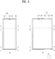
- FIG. 2 is a front view of a first state and a second state of the mobile terminal in accordance with an embodiment
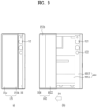
- FIG. 3 is a rear view of the first state and the second state of the mobile terminal in accordance with an embodiment.
- FIGS. 2(a) and 3(a) are views showing the first state in which the mobile terminal is contracted
- FIGS. 2(b) and 3(b) are views showing the second state in which the mobile terminal is extended.
- the mobile terminal 100 in the first state is in a contracted position, and has a smaller size than the mobile terminal 100 in the second state.
- the size of the display unit 151 positioned on the front of the mobile terminal 100 is also smaller than in the second state.
- the mobile terminal 100 in the first state may be extended in a first direction D1 to switch to the second state.
- the size of the mobile terminal 100 and the size of the display unit 151 positioned on the front of the mobile terminal 100 are larger than in the first state, while the size of the display unit 151 positioned on the rear of the mobile terminal 100 is reduced as shown in FIG. 3(b) . That is, a part of the display units 151 positioned on the rear of the mobile terminal 151 in the first state moves to the front of the mobile terminal 100 in the second state.
- first direction D1 the direction in which the mobile terminal 100 and the display unit 151 thereof are extended or enlarged is defined as a first direction D1
- second direction D2 the direction in which the mobile terminal contracts or retracts or is reduced to switch from the second state to the first state is defined as a second direction D2.
- a direction perpendicular to the first and second directions D1 and D2 is defined as a third direction. Description will be made on the assumption that the first and second directions are horizontal directions and the third direction is a vertical direction. However, depending on the arrangement of the mobile terminal 100, the first and second directions may be vertical directions and the third direction may be a horizontal direction.
- a flexible display unit 151 which is bendable may be used as the display unit such that the position of the display unit may be varied.
- the flexible display unit 151 may be a display unit capable of maintaining a flat state like a conventional flat panel display and capable of warping, bending, folding, twisting, or rolling like paper.
- the flexible display unit 151 refers to a display which is manufactured on a thin and flexible substrate and is thus lightweight and robust as not to be easily broken.
- the flexible display unit according the present disclosure may be bent in a specific direction, and may be arranged such that the curvature thereof may change in the first direction.
- a display region of the flexible display unit 151 becomes flat.
- the display region may become a curved face.
- information displayed in the deformation state may be visual information output on the curved face.
- Such visual information is implemented by independently controlling light emission of sub-pixels arranged in a matrix.
- the sub-pixel refers to a minimum unit for implementing one color.
- the flexible display unit 151 When external force is applied to the flexible display unit 151, the flexible display unit 151 may be deformed to switch from the default state, which is the flat state, to a bent state, which is not the flat state.
- the flexible display unit 151 may be combined with a touch sensor to implement a flexible touch screen.
- the controller 180 may perform control corresponding to such touch input.
- the flexible touch screen may be configured to detect the touch input in the deformed state as well as in the basic state.
- the display unit 151 moves to the front face or the rear face of the mobile terminal 100 in different directions (i.e., the first direction D1 or the second direction D2) relative to the second frame 102.
- the roller 210 may guide such movement while rotating.
- the roller 210 may be disposed adjacent to the end of the second frame 102 that faces in the first direction.
- a side frame 1024 may be disposed at the end of the second frame 102 facing in the first direction to prevent damage to the display unit 151 rolled around the roller 210.
- the side frame 1024 may extend in the longitudinal direction (the third direction) of the second frame 102 to cover the side portion facing in the first direction, thereby protecting the roller 210 and the display unit 151 rolled therearound.
- the second frame 102 may overlap the first frame 101, more precisely, the first front portion 1011 and the first rear portion 1012 thereof so as not to interfere with the first frame 101.
- the display unit 151 may be coupled to and supported by the first front portion 1011 of the first frame 101, as described above. Accordingly, the display unit 151 does not need to be additionally supported by the second front portion 1021 of the second frame 102. Rather, when the second front portion 1021 is interposed between the first front portion 1011 and the display unit 151, the display unit 151 may be deformed or damaged because of friction with the second front portion 1021, which is repeatedly moved.
- the first region 151a may be disposed on the front face of the mobile terminal 100, more specifically, the first frame 101, that is, on the front face of the first front portion 1011.
- the first region 151a is fixed to the first frame 101, that is, the front face of the first front portion 1011 so as not to be moved during the movement of the second frame 102, and thus, the first region 151a may always be exposed to the front face of the mobile terminal 100.
- the second region 151b may be adjacent to the third region 151c and may be disposed on the rear face of the mobile terminal 100, more specifically, on the second frame 102, that is, the rear face of the second rear portion 1022 thereof.
- the second region 151b may be coupled to the slide frame 103 without being directly coupled to the second frame 102.
- the state conversion may be performed manually by the user, and an operation of the mobile terminal 100 during such manual state conversion will be described.
- operations of the first to third frames 101 to 103 and the display unit 151 which will be described below, may be performed in the same manner when a power source other than a user's force is used, for example, when the driving unit 200 to be described below is applied.
- a motor 201 configured to provide rotational force as shown in FIG. 7
- a linear motor 201 configured to make linear motion
- the motor 201 configured to provide the rotational force should have a large diameter to provide large force.
- Two motors 201 may be used as shown in FIG. 7 to provide driving force of a predetermined magnitude or more in the limited space of the mobile terminal 100 without increasing the thickness.
- the driving unit 200 When a pair of driving units 200 is symmetrically disposed in the vertical direction (the third direction), stable movement may be made.
- the driving unit 200 should be arranged biased to one side in consideration of the limited mounting space of the mobile terminal 100as shown in FIG. 7(a) .
- the second frame 102 According to such asymmetric arrangement of the driving unit 200, the second frame 102 may be distorted during movement due to a difference in movement speed between the upper end portion and the lower end portion.
- a linear guide 230 may be further provided.
- the linear guide 230 may be disposed at both ends of the mobile terminal 100 facing in the third direction, that is, on the upper and lower sides of the mobile terminal 100, in order to supplement the function of one driving unit 200 biased to one side in the third direction.
- the linear guide 230 may include a guide rail 231 extending in the first direction and a guide block 232 configured to move along the guide rail 231.
- the guide rail 231 may be disposed on the first frame 101 and the guide block 232 may be disposed on the second frame 102, or vice versa.
- the guide rail 231 may be disposed on the second frame 102 to cover the upper and lower sides of the extended portion of the second frame 102 in the second state.
- the guide block 232 and the guide rail 231 may be slidably fastened to each other. However, for convenience of the fastening, the guide block 232 and the guide rail 231 fastened to each other. Then, the guide block 232 may be first fixed to the first frame 101, and then the second frame 102 may be coupled to the guide rail 231.
- the guide block 232 may be provided with a guide groove into which the guide rail 231 is inserted.
- the guide rail 231 may be provided with a rail groove into which a portion of the guide block 232 is inserted.
- the fastening portions of the guide rail 231 and the guide block 232 may be formed to be bumpy. Accordingly, movement in the first direction or the second direction may be made without displacement in the thickness direction of the mobile terminal 100.
- a self-lubricating member having high wear resistance and low friction resistance such as a bearing or polyoxymethylene (POM), may be added to the inside of the guide groove.
- FIG. 8 is a cross-sectional view taken along lines A-A and B-B in FIG. 2 .
- the third region 151c positioned on the rear side moves to the front, and thus a structure to support the rear surface of the third region 151c moved to the front is required.
- the second front portion 1021 positioned on the front surface of the second frame 102 may be positioned on the rear surface of the third region 151c in the second state.
- the second front portion 1021 is disposed to overlap the first front portion 1011 of the first frame 101, and accordingly the first front portion 1011 and the second front portion 1021 form a step.
- a boundary is formed between the first region 151a and the third region 151c of the flexible display unit 151 by the step formed by the first front portion 1011 and the second front portion 1021.
- a rolling plate 104 may be used as a support structure to fill the gap between the second front portion 1021 and the third region 151c of the flexible display unit 151.
- the multiple support bars 1041 may be directly attached to the rear surface of the display unit 151. However, this operation may take a long time and produce a lot of defects, resulting in poor productivity. In addition, directly processing the display unit 151 is highly likely to damage the display unit 151. Therefore, a rolling sheet 1045 to fix the multiple support bars 1041 may be further provided.
- the rolling sheet 1045 may include a metal material, and may employ a superelastic material that is bending-deformable and capable of recovering the flat state after the bending deformation. For example, a superelastic metal sheet such as a thin STS sheet of 0.05 mm or less may be used.
- An adhesive tape may be attached to both surfaces of the rolling sheet 1045 to bond the rolling sheet 1045 to the support bars 1041 and bond the rear surface of the display unit 151 to the rolling sheet 1045.
- the rolling sheet 1045 may be provided with a kerf pattern in which multiple grooves extending in the third direction are formed in the first direction.
- the grooves in the kerf pattern may be formed between the multiple support bars 1041.
- the grooves may be formed on a surface of the rolling sheet 1045 to which the support bars 1041 are bonded.
- the kerf pattern may be formed in a wedge shape that is formed by being gradually narrowed from the surface portion of the rolling sheet 1045.
- the support bars 1041 may form a flat surface corresponding to the rear surface of the display unit 151.
- the support bars 1041 may be formed in a shape having a predetermined curvature.
- the curved support bars 1041 may closely contact the curved surface of the roller 210 when the rolling plate 104 is rolled around the roller 210.
- one surface of the support bars 1041 in contact with the display unit 151 maintains a flat state, and the other surface thereof on the opposite side may include a curved surface corresponding to the curvature of the roller 210.
- the support bars 1041 may be thick at the ends thereof facing in the first and second directions and have the thinnest portion in the middle thereof.
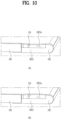
- FIGS. 11 to 13 are views showing the slide structures 1043 and 1027 provided on the rolling plate 104 and the second frame 102.
- FIG. 11 is a cross-sectional view taken along lines C-C and D-D in FIG. 2
- FIG. 12 is a cross-sectional view taken along lines E-E and F-F in FIG. 11
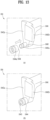
- FIG. 13 is a view showing an expanded side portion 1042 and a guide hook 1043 of the mobile terminal 100 in accordance with an embodiment.
- the slide rail 1041 along which the slide hook 1043 moves may guide the movement of the slide hook 1043 and the movement of the slide frame 103 simultaneously. Since the slide frame 103 is also disposed adjacent to the support bars, a slide hook 1033 protruding from the slide frame 103 may be further provided.
- FIG. 12(a) shows the second frame 102 in the first state in which the first frame 101 and the second frame 102 overlap each other
- FIG. 12(b) shows the second frame 102 moved from the first frame 101 in the first direction in the second state.
- the support bars 1041 and the slide hooks 1043 are positioned on the rear in the first state.
- the support bars 1041 and the slide hooks 1043 are positioned on the front.
- the distance from the front face of the display unit 151 to the front horizontal portions 1027a and 1027b may be equal to the distance from the rear face of the display unit 151 to the rear horizontal portions 1027a and 1027b.
- a self-lubricating member having high abrasion resistance and low friction resistance such as polyoxymethylene (POM) may be used to facilitate the movement of the slide hooks 1043 on the slide rail 1027.
- POM polyoxymethylene
- a slide roller 1044 fitted onto the slide hook 1043 may be further provided.
- the slide roller 1044 may be fitted onto the cylindrical slide hook 1043 to rotate about an axis extending in a direction in which the slide hook 1043 protrudes.
- the slide roller 1044 may rotate when the slide hook 1043 moves along the slide rail 1027, thereby reducing friction generated between the slide roller 1044 and the slide rail 1027.
- a bearing structure may help to reduce the friction, but it may increase the overall size. For this reason, a simple ring-shaped slide roller 1044 may be used.
- a fastening groove 1043a and a fastening protrusion 1044a may be further provided to prevent the slide roller 1044 from being separated from the slide hook 1043.
- the second side portion 1023 of the second frame 102 is disposed overlapping the first side portion 1013 of the first frame 101 in the first state, and is exposed to the outside in the second state. Since the second side portion 1023 is positioned inside the first side portion 1013 of the first frame 101 in the first state, it may be difficult to connect the interface unit 160, the user input unit 123, the audio output unit 152, the antenna, and the like, which are positioned on the first side portion 1013, to the printed circuit board 181, which is positioned inside.
- the second side portion 1023 may include an opening 1023a formed by omitting at least a part of the second side portion 1023 to connect the components positioned on the first side portion 1013 to the printed circuit board 181 positioned inside the first frame 101. Through the opening 1023a, a connector may be arranged between the components positioned on the first side portion 1013 and the printed circuit board.
- the opening 1023a may have a shape elongated in the first direction to prevent interference between the connector and the second side portion 1023 of the second frame 102 even when the second frame 102 is moved.
- an expanded side portion 1042 may be formed at an end of the support bar 1041 to cover the opening 1023a in the second state.
- the expanded side portion 1042 may have a larger area than the cross section of the support bar 1041 at the end of the support bar 1041.
- the slide hook 1043 may be formed on a first expanded side portion 1042a extending in a direction away from the display unit 151. When the slide hook 1043 is disposed parallel to the support bar 1041, the second side portion 1023 of the second frame 102 should be extended adjacent to the display unit 151, which may make it difficult to form the opening 1023a.
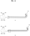
- the second expanded side portion 1042b may have any shape as long as the shape ensures that the second expanded side portions 1042b do not interfere with each other, and allows the second expanded side portion 1042b to cover the space between the first expanded side portions 1042a and to cover the opening 1023a of the second side portion 1023 of the frame 102. It may have a rectangular shape as shown in FIG. 14(a) or a semicircular shape as shown in FIG. 14(b) .
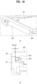
- FIG. 16 is a view showing a rolling ball 1029 employed to address the issue illustrated in FIG. 15 .
- the rolling ball 1029 is inserted into a concave insertion portion formed in the second side portion 1023 of the second frame 102.
- the rolling ball 1029 may be in contact with the first frame 101 on one side and may rotate within the insertion portion of the second side portion when the second frame 102 moves in the first direction.
- the rolling ball 1029 may be displaced in the assembly process because the second frame 102 has no structure to fix the rolling ball 1029.
- FIG. 16 is a view showing a rolling ball 1029 employed to address the issue illustrated in FIG. 15 .
- the rolling ball 1029 is inserted into a concave insertion portion formed in the second side portion 1023 of the second frame 102.
- the rolling ball 1029 may be in contact with the first frame 101 on one side and may rotate within the insertion portion of the second side portion when the second frame 102 moves in the first direction.
- the rolling ball 1029 may be displaced in
- a magnet 1029' may be placed inside the insertion portion, and the rolling ball 1029 may be made of a magnetic material. Thereby, the rolling ball 1029 may be prevented from being displaced from the insertion portion when the first frame 101 and the second frame 102 are connected.
- the rolling ball 1029 may protrude as far as the gap between the first frame 101 and the second frame 102 to contact the first frame 101. Thereby, the second frame 102 may be prevented from being distorted due to the gap. In addition, since the second frame 102 is spaced apart from the first frame 101 by a predetermined distance rather than directly contacting the first frame 101 and the rolling ball 1029 rotates during movement of the second frame 102, friction generated when the mobile terminal switches between the states may be minimized.
- the mobile terminal of the present disclosure may allow the size of the screen to be adjusted as needed, thereby satisfying both portability and usability.
Landscapes
- Engineering & Computer Science (AREA)
- Theoretical Computer Science (AREA)
- Computer Hardware Design (AREA)
- Signal Processing (AREA)
- Physics & Mathematics (AREA)
- Human Computer Interaction (AREA)
- General Engineering & Computer Science (AREA)
- General Physics & Mathematics (AREA)
- Microelectronics & Electronic Packaging (AREA)
- Mathematical Physics (AREA)
- Telephone Set Structure (AREA)
- Devices For Indicating Variable Information By Combining Individual Elements (AREA)
Applications Claiming Priority (2)
| Application Number | Priority Date | Filing Date | Title |
|---|---|---|---|
| PCT/KR2020/095006 WO2021167236A1 (ko) | 2020-02-20 | 2020-02-20 | 이동 단말기 |
| EP20189987.9A EP3869296B1 (de) | 2020-02-20 | 2020-08-07 | Mobiles endgerät |
Related Parent Applications (2)
| Application Number | Title | Priority Date | Filing Date |
|---|---|---|---|
| EP20189987.9A Division-Into EP3869296B1 (de) | 2020-02-20 | 2020-08-07 | Mobiles endgerät |
| EP20189987.9A Division EP3869296B1 (de) | 2020-02-20 | 2020-08-07 | Mobiles endgerät |
Publications (3)
| Publication Number | Publication Date |
|---|---|
| EP4246502A2 true EP4246502A2 (de) | 2023-09-20 |
| EP4246502A3 EP4246502A3 (de) | 2024-01-03 |
| EP4246502B1 EP4246502B1 (de) | 2024-12-25 |
Family
ID=71995817
Family Applications (2)
| Application Number | Title | Priority Date | Filing Date |
|---|---|---|---|
| EP20189987.9A Active EP3869296B1 (de) | 2020-02-20 | 2020-08-07 | Mobiles endgerät |
| EP23185193.2A Active EP4246502B1 (de) | 2020-02-20 | 2020-08-07 | Mobiles endgerät |
Family Applications Before (1)
| Application Number | Title | Priority Date | Filing Date |
|---|---|---|---|
| EP20189987.9A Active EP3869296B1 (de) | 2020-02-20 | 2020-08-07 | Mobiles endgerät |
Country Status (4)
| Country | Link |
|---|---|
| US (1) | US12284300B2 (de) |
| EP (2) | EP3869296B1 (de) |
| KR (1) | KR102892373B1 (de) |
| WO (1) | WO2021167236A1 (de) |
Families Citing this family (12)
| Publication number | Priority date | Publication date | Assignee | Title |
|---|---|---|---|---|
| KR102767421B1 (ko) * | 2020-04-28 | 2025-02-14 | 삼성전자 주식회사 | 비금속 물질을 포함하는 하우징 및 안테나를 포함하는 전자 장치 |
| EP4191367A4 (de) * | 2020-10-12 | 2024-01-10 | Samsung Electronics Co., Ltd. | Elektronische vorrichtung mit flexibler anzeige |
| CN113411427B (zh) * | 2021-06-25 | 2024-02-27 | 维沃移动通信有限公司 | 电子设备 |
| KR20230017621A (ko) * | 2021-07-28 | 2023-02-06 | 엘지디스플레이 주식회사 | 롤-슬라이드 표시 장치 |
| KR20230043303A (ko) * | 2021-09-23 | 2023-03-31 | 삼성디스플레이 주식회사 | 표시장치 |
| CN117501206A (zh) | 2021-11-11 | 2024-02-02 | 三星电子株式会社 | 可卷曲电子装置 |
| CN114170911A (zh) * | 2021-12-15 | 2022-03-11 | 武汉华星光电半导体显示技术有限公司 | 可滑动的显示装置 |
| EP4276577A4 (de) * | 2022-04-01 | 2024-08-21 | Samsung Electronics Co., Ltd. | Elektronische vorrichtung mit flexibler anzeige |
| US20250126726A1 (en) * | 2022-05-26 | 2025-04-17 | Beijing Xiaomi Mobile Software Co., Ltd. | Electronic device |
| CN117523970A (zh) * | 2022-07-27 | 2024-02-06 | Oppo广东移动通信有限公司 | 支撑装置、壳体及电子设备 |
| US20250089185A1 (en) * | 2022-09-28 | 2025-03-13 | Boe Technology Group Co., Ltd. | Display Module and Display Apparatus |
| WO2025116289A1 (ko) * | 2023-11-29 | 2025-06-05 | 삼성전자 주식회사 | 지지어셈블리를 포함하는 전자장치 |
Family Cites Families (15)
| Publication number | Priority date | Publication date | Assignee | Title |
|---|---|---|---|---|
| KR20130010676A (ko) * | 2011-07-19 | 2013-01-29 | 김수호 | 이단 커튼레일용 커튼롤러 |
| CN102280077B (zh) * | 2011-08-17 | 2013-09-04 | 深圳市立翔慧科光电科技有限公司 | 一种灯条式led显示屏 |
| KR20160050698A (ko) * | 2014-10-30 | 2016-05-11 | 엘지전자 주식회사 | 이동 단말기 |
| KR102306982B1 (ko) | 2015-05-29 | 2021-10-01 | 엘지디스플레이 주식회사 | 슬라이더블 디스플레이 |
| US9625948B2 (en) * | 2015-08-24 | 2017-04-18 | Apple Inc. | Electronic devices with retractable displays |
| US10056443B2 (en) * | 2016-04-08 | 2018-08-21 | Apple Inc. | Electronic devices with displays |
| KR20170116551A (ko) * | 2016-04-11 | 2017-10-19 | 박현민 | 연성 디스플레이 패널용 슬라이딩 모듈 |
| KR102396167B1 (ko) * | 2016-04-12 | 2022-05-11 | 삼성전자 주식회사 | 플렉서블 전자 장치 |
| KR102547146B1 (ko) | 2016-07-07 | 2023-06-23 | 삼성디스플레이 주식회사 | 롤러블 디스플레이 장치 |
| CN107170370A (zh) * | 2017-05-12 | 2017-09-15 | 京东方科技集团股份有限公司 | 显示模组 |
| CN108259649B (zh) * | 2018-02-09 | 2021-07-30 | 西安中兴新软件有限责任公司 | 一种移动终端、控制系统和控制方法 |
| KR102269604B1 (ko) | 2018-02-23 | 2021-06-28 | 삼성전자주식회사 | 이동 가능한 플렉서블 디스플레이를 포함하는 전자 장치 |
| KR102460471B1 (ko) * | 2018-03-27 | 2022-10-28 | 삼성전자주식회사 | 이동 가능한 플렉서블 디스플레이를 포함하는 전자 장치 및 그 동작 방법 |
| KR102458690B1 (ko) | 2018-04-04 | 2022-10-25 | 삼성전자주식회사 | 무선 충전 모듈 및 플렉서블 디스플레이를 포함하는 전자 장치 |
| US10904371B1 (en) * | 2020-07-24 | 2021-01-26 | Lg Electronics Inc. | Mobile terminal |
-
2020
- 2020-02-20 WO PCT/KR2020/095006 patent/WO2021167236A1/ko not_active Ceased
- 2020-02-20 US US17/904,725 patent/US12284300B2/en active Active
- 2020-02-20 KR KR1020227023919A patent/KR102892373B1/ko active Active
- 2020-08-07 EP EP20189987.9A patent/EP3869296B1/de active Active
- 2020-08-07 EP EP23185193.2A patent/EP4246502B1/de active Active
Also Published As
| Publication number | Publication date |
|---|---|
| EP3869296B1 (de) | 2023-10-04 |
| KR102892373B1 (ko) | 2025-12-01 |
| KR20220118465A (ko) | 2022-08-25 |
| US20230075243A1 (en) | 2023-03-09 |
| EP3869296A1 (de) | 2021-08-25 |
| EP4246502B1 (de) | 2024-12-25 |
| EP4246502A3 (de) | 2024-01-03 |
| WO2021167236A1 (ko) | 2021-08-26 |
| US12284300B2 (en) | 2025-04-22 |
Similar Documents
| Publication | Publication Date | Title |
|---|---|---|
| US10904371B1 (en) | Mobile terminal | |
| EP3869297B1 (de) | Mobiles endgerät | |
| US11012546B1 (en) | Mobile terminal | |
| US11343364B2 (en) | Mobile terminal including display subjectable to bending deformation | |
| US10880417B1 (en) | Mobile terminal | |
| EP3885873B1 (de) | Mobiles endgerät | |
| EP4246502B1 (de) | Mobiles endgerät | |
| US20210326569A1 (en) | Mobile terminal | |
| EP3944597B1 (de) | Schiebbares mobiles endgerät | |
| US11042195B1 (en) | Mobile terminal | |
| US11330089B2 (en) | Mobile terminal | |
| EP3964918B1 (de) | Mobiles endgerät | |
| EP4120667A1 (de) | Mobiles endgerät | |
| US11435783B2 (en) | Mobile terminal | |
| US10893130B1 (en) | Mobile terminal | |
| US12418602B2 (en) | Mobile terminal | |
| EP3944598B1 (de) | Schiebbares mobiles endgerät | |
| US20210329106A1 (en) | Mobile terminal | |
| US12581000B2 (en) | Mobile terminal | |
| US12530053B2 (en) | Mobile terminal | |
| EP3869295A1 (de) | Mobiles endgerät | |
| US12381968B2 (en) | Mobile terminal |
Legal Events
| Date | Code | Title | Description |
|---|---|---|---|
| PUAI | Public reference made under article 153(3) epc to a published international application that has entered the european phase |
Free format text: ORIGINAL CODE: 0009012 |
|
| STAA | Information on the status of an ep patent application or granted ep patent |
Free format text: STATUS: THE APPLICATION HAS BEEN PUBLISHED |
|
| AC | Divisional application: reference to earlier application |
Ref document number: 3869296 Country of ref document: EP Kind code of ref document: P |
|
| AK | Designated contracting states |
Kind code of ref document: A2 Designated state(s): AL AT BE BG CH CY CZ DE DK EE ES FI FR GB GR HR HU IE IS IT LI LT LU LV MC MK MT NL NO PL PT RO RS SE SI SK SM TR |
|
| REG | Reference to a national code |
Ref country code: DE Ref legal event code: R079 Free format text: PREVIOUS MAIN CLASS: G09F0009300000 Ipc: G06F0001160000 Ref country code: DE Ref legal event code: R079 Ref document number: 602020043900 Country of ref document: DE Free format text: PREVIOUS MAIN CLASS: G09F0009300000 Ipc: G06F0001160000 |
|
| PUAL | Search report despatched |
Free format text: ORIGINAL CODE: 0009013 |
|
| AK | Designated contracting states |
Kind code of ref document: A3 Designated state(s): AL AT BE BG CH CY CZ DE DK EE ES FI FR GB GR HR HU IE IS IT LI LT LU LV MC MK MT NL NO PL PT RO RS SE SI SK SM TR |
|
| RIC1 | Information provided on ipc code assigned before grant |
Ipc: G09F 9/30 20060101ALI20231124BHEP Ipc: H04M 1/02 20060101ALI20231124BHEP Ipc: G06F 1/16 20060101AFI20231124BHEP |
|
| STAA | Information on the status of an ep patent application or granted ep patent |
Free format text: STATUS: REQUEST FOR EXAMINATION WAS MADE |
|
| 17P | Request for examination filed |
Effective date: 20240702 |
|
| GRAP | Despatch of communication of intention to grant a patent |
Free format text: ORIGINAL CODE: EPIDOSNIGR1 |
|
| RBV | Designated contracting states (corrected) |
Designated state(s): AL AT BE BG CH CY CZ DE DK EE ES FI FR GB GR HR HU IE IS IT LI LT LU LV MC MK MT NL NO PL PT RO RS SE SI SK SM TR |
|
| STAA | Information on the status of an ep patent application or granted ep patent |
Free format text: STATUS: GRANT OF PATENT IS INTENDED |
|
| RIC1 | Information provided on ipc code assigned before grant |
Ipc: G09F 9/30 20060101ALI20240730BHEP Ipc: H04M 1/02 20060101ALI20240730BHEP Ipc: G06F 1/16 20060101AFI20240730BHEP |
|
| INTG | Intention to grant announced |
Effective date: 20240808 |
|
| GRAS | Grant fee paid |
Free format text: ORIGINAL CODE: EPIDOSNIGR3 |
|
| GRAA | (expected) grant |
Free format text: ORIGINAL CODE: 0009210 |
|
| STAA | Information on the status of an ep patent application or granted ep patent |
Free format text: STATUS: THE PATENT HAS BEEN GRANTED |
|
| AC | Divisional application: reference to earlier application |
Ref document number: 3869296 Country of ref document: EP Kind code of ref document: P |
|
| AK | Designated contracting states |
Kind code of ref document: B1 Designated state(s): AL AT BE BG CH CY CZ DE DK EE ES FI FR GB GR HR HU IE IS IT LI LT LU LV MC MK MT NL NO PL PT RO RS SE SI SK SM TR |
|
| REG | Reference to a national code |
Ref country code: GB Ref legal event code: FG4D |
|
| REG | Reference to a national code |
Ref country code: CH Ref legal event code: EP |
|
| REG | Reference to a national code |
Ref country code: DE Ref legal event code: R096 Ref document number: 602020043900 Country of ref document: DE |
|
| REG | Reference to a national code |
Ref country code: IE Ref legal event code: FG4D |
|
| REG | Reference to a national code |
Ref country code: LT Ref legal event code: MG9D |
|
| PG25 | Lapsed in a contracting state [announced via postgrant information from national office to epo] |
Ref country code: HR Free format text: LAPSE BECAUSE OF FAILURE TO SUBMIT A TRANSLATION OF THE DESCRIPTION OR TO PAY THE FEE WITHIN THE PRESCRIBED TIME-LIMIT Effective date: 20241225 |
|
| PG25 | Lapsed in a contracting state [announced via postgrant information from national office to epo] |
Ref country code: FI Free format text: LAPSE BECAUSE OF FAILURE TO SUBMIT A TRANSLATION OF THE DESCRIPTION OR TO PAY THE FEE WITHIN THE PRESCRIBED TIME-LIMIT Effective date: 20241225 |
|
| PG25 | Lapsed in a contracting state [announced via postgrant information from national office to epo] |
Ref country code: BG Free format text: LAPSE BECAUSE OF FAILURE TO SUBMIT A TRANSLATION OF THE DESCRIPTION OR TO PAY THE FEE WITHIN THE PRESCRIBED TIME-LIMIT Effective date: 20241225 |
|
| PG25 | Lapsed in a contracting state [announced via postgrant information from national office to epo] |
Ref country code: NO Free format text: LAPSE BECAUSE OF FAILURE TO SUBMIT A TRANSLATION OF THE DESCRIPTION OR TO PAY THE FEE WITHIN THE PRESCRIBED TIME-LIMIT Effective date: 20250325 |
|
| PG25 | Lapsed in a contracting state [announced via postgrant information from national office to epo] |
Ref country code: LV Free format text: LAPSE BECAUSE OF FAILURE TO SUBMIT A TRANSLATION OF THE DESCRIPTION OR TO PAY THE FEE WITHIN THE PRESCRIBED TIME-LIMIT Effective date: 20241225 Ref country code: GR Free format text: LAPSE BECAUSE OF FAILURE TO SUBMIT A TRANSLATION OF THE DESCRIPTION OR TO PAY THE FEE WITHIN THE PRESCRIBED TIME-LIMIT Effective date: 20250326 |
|
| PG25 | Lapsed in a contracting state [announced via postgrant information from national office to epo] |
Ref country code: RS Free format text: LAPSE BECAUSE OF FAILURE TO SUBMIT A TRANSLATION OF THE DESCRIPTION OR TO PAY THE FEE WITHIN THE PRESCRIBED TIME-LIMIT Effective date: 20250325 |
|
| REG | Reference to a national code |
Ref country code: NL Ref legal event code: MP Effective date: 20241225 |
|
| PG25 | Lapsed in a contracting state [announced via postgrant information from national office to epo] |
Ref country code: NL Free format text: LAPSE BECAUSE OF FAILURE TO SUBMIT A TRANSLATION OF THE DESCRIPTION OR TO PAY THE FEE WITHIN THE PRESCRIBED TIME-LIMIT Effective date: 20241225 |
|
| REG | Reference to a national code |
Ref country code: AT Ref legal event code: MK05 Ref document number: 1754727 Country of ref document: AT Kind code of ref document: T Effective date: 20241225 |
|
| PG25 | Lapsed in a contracting state [announced via postgrant information from national office to epo] |
Ref country code: SM Free format text: LAPSE BECAUSE OF FAILURE TO SUBMIT A TRANSLATION OF THE DESCRIPTION OR TO PAY THE FEE WITHIN THE PRESCRIBED TIME-LIMIT Effective date: 20241225 |
|
| PG25 | Lapsed in a contracting state [announced via postgrant information from national office to epo] |
Ref country code: PL Free format text: LAPSE BECAUSE OF FAILURE TO SUBMIT A TRANSLATION OF THE DESCRIPTION OR TO PAY THE FEE WITHIN THE PRESCRIBED TIME-LIMIT Effective date: 20241225 |
|
| PG25 | Lapsed in a contracting state [announced via postgrant information from national office to epo] |
Ref country code: ES Free format text: LAPSE BECAUSE OF FAILURE TO SUBMIT A TRANSLATION OF THE DESCRIPTION OR TO PAY THE FEE WITHIN THE PRESCRIBED TIME-LIMIT Effective date: 20241225 |
|
| PG25 | Lapsed in a contracting state [announced via postgrant information from national office to epo] |
Ref country code: IS Free format text: LAPSE BECAUSE OF FAILURE TO SUBMIT A TRANSLATION OF THE DESCRIPTION OR TO PAY THE FEE WITHIN THE PRESCRIBED TIME-LIMIT Effective date: 20250425 |
|
| PG25 | Lapsed in a contracting state [announced via postgrant information from national office to epo] |
Ref country code: PT Free format text: LAPSE BECAUSE OF FAILURE TO SUBMIT A TRANSLATION OF THE DESCRIPTION OR TO PAY THE FEE WITHIN THE PRESCRIBED TIME-LIMIT Effective date: 20250428 |
|
| PG25 | Lapsed in a contracting state [announced via postgrant information from national office to epo] |
Ref country code: EE Free format text: LAPSE BECAUSE OF FAILURE TO SUBMIT A TRANSLATION OF THE DESCRIPTION OR TO PAY THE FEE WITHIN THE PRESCRIBED TIME-LIMIT Effective date: 20241225 |
|
| PG25 | Lapsed in a contracting state [announced via postgrant information from national office to epo] |
Ref country code: RO Free format text: LAPSE BECAUSE OF FAILURE TO SUBMIT A TRANSLATION OF THE DESCRIPTION OR TO PAY THE FEE WITHIN THE PRESCRIBED TIME-LIMIT Effective date: 20241225 Ref country code: AT Free format text: LAPSE BECAUSE OF FAILURE TO SUBMIT A TRANSLATION OF THE DESCRIPTION OR TO PAY THE FEE WITHIN THE PRESCRIBED TIME-LIMIT Effective date: 20241225 |
|
| PG25 | Lapsed in a contracting state [announced via postgrant information from national office to epo] |
Ref country code: SK Free format text: LAPSE BECAUSE OF FAILURE TO SUBMIT A TRANSLATION OF THE DESCRIPTION OR TO PAY THE FEE WITHIN THE PRESCRIBED TIME-LIMIT Effective date: 20241225 |
|
| PG25 | Lapsed in a contracting state [announced via postgrant information from national office to epo] |
Ref country code: CZ Free format text: LAPSE BECAUSE OF FAILURE TO SUBMIT A TRANSLATION OF THE DESCRIPTION OR TO PAY THE FEE WITHIN THE PRESCRIBED TIME-LIMIT Effective date: 20241225 |
|
| PG25 | Lapsed in a contracting state [announced via postgrant information from national office to epo] |
Ref country code: IT Free format text: LAPSE BECAUSE OF FAILURE TO SUBMIT A TRANSLATION OF THE DESCRIPTION OR TO PAY THE FEE WITHIN THE PRESCRIBED TIME-LIMIT Effective date: 20241225 |
|
| PG25 | Lapsed in a contracting state [announced via postgrant information from national office to epo] |
Ref country code: SE Free format text: LAPSE BECAUSE OF FAILURE TO SUBMIT A TRANSLATION OF THE DESCRIPTION OR TO PAY THE FEE WITHIN THE PRESCRIBED TIME-LIMIT Effective date: 20241225 |
|
| REG | Reference to a national code |
Ref country code: DE Ref legal event code: R097 Ref document number: 602020043900 Country of ref document: DE |
|
| PG25 | Lapsed in a contracting state [announced via postgrant information from national office to epo] |
Ref country code: DK Free format text: LAPSE BECAUSE OF FAILURE TO SUBMIT A TRANSLATION OF THE DESCRIPTION OR TO PAY THE FEE WITHIN THE PRESCRIBED TIME-LIMIT Effective date: 20241225 |
|
| PGFP | Annual fee paid to national office [announced via postgrant information from national office to epo] |
Ref country code: DE Payment date: 20250707 Year of fee payment: 6 |
|
| PGFP | Annual fee paid to national office [announced via postgrant information from national office to epo] |
Ref country code: FR Payment date: 20250715 Year of fee payment: 6 |
|
| PLBE | No opposition filed within time limit |
Free format text: ORIGINAL CODE: 0009261 |
|
| STAA | Information on the status of an ep patent application or granted ep patent |
Free format text: STATUS: NO OPPOSITION FILED WITHIN TIME LIMIT |
|
| REG | Reference to a national code |
Ref country code: CH Ref legal event code: L10 Free format text: ST27 STATUS EVENT CODE: U-0-0-L10-L00 (AS PROVIDED BY THE NATIONAL OFFICE) Effective date: 20251105 |
|
| 26N | No opposition filed |
Effective date: 20250926 |
|
| REG | Reference to a national code |
Ref country code: CH Ref legal event code: H13 Free format text: ST27 STATUS EVENT CODE: U-0-0-H10-H13 (AS PROVIDED BY THE NATIONAL OFFICE) Effective date: 20260324 |
|
| PG25 | Lapsed in a contracting state [announced via postgrant information from national office to epo] |
Ref country code: MC Free format text: LAPSE BECAUSE OF FAILURE TO SUBMIT A TRANSLATION OF THE DESCRIPTION OR TO PAY THE FEE WITHIN THE PRESCRIBED TIME-LIMIT Effective date: 20241225 |
|
| PG25 | Lapsed in a contracting state [announced via postgrant information from national office to epo] |
Ref country code: LU Free format text: LAPSE BECAUSE OF NON-PAYMENT OF DUE FEES Effective date: 20250807 |