EP4246413A1 - Battery production system and management method therefor - Google Patents
Battery production system and management method therefor Download PDFInfo
- Publication number
- EP4246413A1 EP4246413A1 EP22867574.0A EP22867574A EP4246413A1 EP 4246413 A1 EP4246413 A1 EP 4246413A1 EP 22867574 A EP22867574 A EP 22867574A EP 4246413 A1 EP4246413 A1 EP 4246413A1
- Authority
- EP
- European Patent Office
- Prior art keywords
- tray
- impact
- collectors
- server
- production system
- Prior art date
- Legal status (The legal status is an assumption and is not a legal conclusion. Google has not performed a legal analysis and makes no representation as to the accuracy of the status listed.)
- Granted
Links
Images



Classifications
-
- G—PHYSICS
- G01—MEASURING; TESTING
- G01P—MEASURING LINEAR OR ANGULAR SPEED, ACCELERATION, DECELERATION, OR SHOCK; INDICATING PRESENCE, ABSENCE, OR DIRECTION, OF MOVEMENT
- G01P15/00—Measuring acceleration; Measuring deceleration; Measuring shock, i.e. sudden change of acceleration
-
- H—ELECTRICITY
- H04—ELECTRIC COMMUNICATION TECHNIQUE
- H04W—WIRELESS COMMUNICATION NETWORKS
- H04W4/00—Services specially adapted for wireless communication networks; Facilities therefor
- H04W4/02—Services making use of location information
- H04W4/029—Location-based management or tracking services
-
- G—PHYSICS
- G01—MEASURING; TESTING
- G01L—MEASURING FORCE, STRESS, TORQUE, WORK, MECHANICAL POWER, MECHANICAL EFFICIENCY, OR FLUID PRESSURE
- G01L5/00—Apparatus for, or methods of, measuring force, work, mechanical power, or torque, specially adapted for specific purposes
- G01L5/0052—Apparatus for, or methods of, measuring force, work, mechanical power, or torque, specially adapted for specific purposes measuring forces due to impact
-
- G—PHYSICS
- G01—MEASURING; TESTING
- G01P—MEASURING LINEAR OR ANGULAR SPEED, ACCELERATION, DECELERATION, OR SHOCK; INDICATING PRESENCE, ABSENCE, OR DIRECTION, OF MOVEMENT
- G01P15/00—Measuring acceleration; Measuring deceleration; Measuring shock, i.e. sudden change of acceleration
- G01P15/02—Measuring acceleration; Measuring deceleration; Measuring shock, i.e. sudden change of acceleration by making use of inertia forces using solid seismic masses
- G01P15/08—Measuring acceleration; Measuring deceleration; Measuring shock, i.e. sudden change of acceleration by making use of inertia forces using solid seismic masses with conversion into electric or magnetic values
- G01P15/0891—Measuring acceleration; Measuring deceleration; Measuring shock, i.e. sudden change of acceleration by making use of inertia forces using solid seismic masses with conversion into electric or magnetic values with indication of predetermined acceleration values
-
- G—PHYSICS
- G01—MEASURING; TESTING
- G01S—RADIO DIRECTION-FINDING; RADIO NAVIGATION; DETERMINING DISTANCE OR VELOCITY BY USE OF RADIO WAVES; LOCATING OR PRESENCE-DETECTING BY USE OF THE REFLECTION OR RERADIATION OF RADIO WAVES; ANALOGOUS ARRANGEMENTS USING OTHER WAVES
- G01S13/00—Systems using the reflection or reradiation of radio waves, e.g. radar systems; Analogous systems using reflection or reradiation of waves whose nature or wavelength is irrelevant or unspecified
- G01S13/74—Systems using reradiation of radio waves, e.g. secondary radar systems; Analogous systems
-
- G—PHYSICS
- G06—COMPUTING OR CALCULATING; COUNTING
- G06Q—INFORMATION AND COMMUNICATION TECHNOLOGY [ICT] SPECIALLY ADAPTED FOR ADMINISTRATIVE, COMMERCIAL, FINANCIAL, MANAGERIAL OR SUPERVISORY PURPOSES; SYSTEMS OR METHODS SPECIALLY ADAPTED FOR ADMINISTRATIVE, COMMERCIAL, FINANCIAL, MANAGERIAL OR SUPERVISORY PURPOSES, NOT OTHERWISE PROVIDED FOR
- G06Q10/00—Administration; Management
- G06Q10/08—Logistics, e.g. warehousing, loading or distribution; Inventory or stock management
-
- G—PHYSICS
- G06—COMPUTING OR CALCULATING; COUNTING
- G06Q—INFORMATION AND COMMUNICATION TECHNOLOGY [ICT] SPECIALLY ADAPTED FOR ADMINISTRATIVE, COMMERCIAL, FINANCIAL, MANAGERIAL OR SUPERVISORY PURPOSES; SYSTEMS OR METHODS SPECIALLY ADAPTED FOR ADMINISTRATIVE, COMMERCIAL, FINANCIAL, MANAGERIAL OR SUPERVISORY PURPOSES, NOT OTHERWISE PROVIDED FOR
- G06Q50/00—Information and communication technology [ICT] specially adapted for implementation of business processes of specific business sectors, e.g. utilities or tourism
- G06Q50/04—Manufacturing
-
- H—ELECTRICITY
- H01—ELECTRIC ELEMENTS
- H01M—PROCESSES OR MEANS, e.g. BATTERIES, FOR THE DIRECT CONVERSION OF CHEMICAL ENERGY INTO ELECTRICAL ENERGY
- H01M50/00—Constructional details or processes of manufacture of the non-active parts of electrochemical cells other than fuel cells, e.g. hybrid cells
- H01M50/20—Mountings; Secondary casings or frames; Racks, modules or packs; Suspension devices; Shock absorbers; Transport or carrying devices; Holders
-
- H—ELECTRICITY
- H04—ELECTRIC COMMUNICATION TECHNIQUE
- H04W—WIRELESS COMMUNICATION NETWORKS
- H04W4/00—Services specially adapted for wireless communication networks; Facilities therefor
- H04W4/02—Services making use of location information
- H04W4/023—Services making use of location information using mutual or relative location information between multiple location based services [LBS] targets or of distance thresholds
-
- H—ELECTRICITY
- H04—ELECTRIC COMMUNICATION TECHNIQUE
- H04W—WIRELESS COMMUNICATION NETWORKS
- H04W4/00—Services specially adapted for wireless communication networks; Facilities therefor
- H04W4/30—Services specially adapted for particular environments, situations or purposes
- H04W4/38—Services specially adapted for particular environments, situations or purposes for collecting sensor information
-
- H—ELECTRICITY
- H01—ELECTRIC ELEMENTS
- H01M—PROCESSES OR MEANS, e.g. BATTERIES, FOR THE DIRECT CONVERSION OF CHEMICAL ENERGY INTO ELECTRICAL ENERGY
- H01M10/00—Secondary cells; Manufacture thereof
- H01M10/42—Methods or arrangements for servicing or maintenance of secondary cells or secondary half-cells
- H01M10/425—Structural combination with electronic components, e.g. electronic circuits integrated to the outside of the casing
- H01M2010/4278—Systems for data transfer from batteries, e.g. transfer of battery parameters to a controller, data transferred between battery controller and main controller
-
- Y—GENERAL TAGGING OF NEW TECHNOLOGICAL DEVELOPMENTS; GENERAL TAGGING OF CROSS-SECTIONAL TECHNOLOGIES SPANNING OVER SEVERAL SECTIONS OF THE IPC; TECHNICAL SUBJECTS COVERED BY FORMER USPC CROSS-REFERENCE ART COLLECTIONS [XRACs] AND DIGESTS
- Y02—TECHNOLOGIES OR APPLICATIONS FOR MITIGATION OR ADAPTATION AGAINST CLIMATE CHANGE
- Y02E—REDUCTION OF GREENHOUSE GAS [GHG] EMISSIONS, RELATED TO ENERGY GENERATION, TRANSMISSION OR DISTRIBUTION
- Y02E60/00—Enabling technologies; Technologies with a potential or indirect contribution to GHG emissions mitigation
- Y02E60/10—Energy storage using batteries
-
- Y—GENERAL TAGGING OF NEW TECHNOLOGICAL DEVELOPMENTS; GENERAL TAGGING OF CROSS-SECTIONAL TECHNOLOGIES SPANNING OVER SEVERAL SECTIONS OF THE IPC; TECHNICAL SUBJECTS COVERED BY FORMER USPC CROSS-REFERENCE ART COLLECTIONS [XRACs] AND DIGESTS
- Y02—TECHNOLOGIES OR APPLICATIONS FOR MITIGATION OR ADAPTATION AGAINST CLIMATE CHANGE
- Y02P—CLIMATE CHANGE MITIGATION TECHNOLOGIES IN THE PRODUCTION OR PROCESSING OF GOODS
- Y02P70/00—Climate change mitigation technologies in the production process for final industrial or consumer products
- Y02P70/50—Manufacturing or production processes characterised by the final manufactured product
Definitions
- Embodiments disclosed herein relate to a battery production system and management thereof.
- the secondary batteries which are chargeable/dischargeable batteries, may include all of conventional nickel (Ni)/cadmium (Cd) batteries, Ni/metal hydride (MH) batteries, etc., and recent lithium-ion batteries.
- a lithium-ion battery has a much higher energy density than those of the conventional Ni/Cd batteries, Ni/MH batteries, etc.
- the lithium-ion battery may be manufactured to be small and lightweight, such that the lithium-ion battery has been used as a power source of mobile devices.
- the lithium ion battery is attracting attention as a next-generation energy storage medium as a usage range thereof is expanded to a power source of electric vehicles.
- a battery In a battery production system, a battery is moved through a conveyor belt while being carried on a tray, and may be damaged for various reasons in a logistics movement process. For example, when logistics are congested in a specific section of the conveyor belt, cracks may occur due to collisions between logistics, leading to deterioration of battery product quality. Thus, proactive or follow-up management of product quality deterioration occurring in logistics movement in a battery production system is required.
- a battery production system disclosed herein includes a tray including a battery, a plurality of collectors configured to perform wireless communication with the tray, and a server configured to track a position of the tray and whether an impact occurs in the tray based on information received from the plurality of collectors, in which the tray includes a measurement unit configured to sense an impact and a communication unit configured to perform wireless communication with the plurality of collectors, the measurement unit is configured to reduce a measurement interval at a designated first rate upon sensing the impact, and the communication unit is configured to reduce an interval of the wireless communication at a designated second rate upon sensing the impact.
- An operating method of a battery production system disclosed herein includes operations of sensing, by a tray, whether an impact occurs at designated measurement intervals, performing, by the tray, wireless communication with a plurality of collectors, upon sensing the impact, reducing, by the tray, a measurement interval at a designated first rate and reducing an interval of the wireless communication at a designated second rate, transmitting, by the plurality of collectors, a result of the wireless communication with the tray to a server, and determining, by the server, a position of the tray and whether an impact occurs in the tray based on information received from the plurality of collectors.
- a battery production system may check in advance factors of battery product quality deterioration occurring in logistics movement by tracking in real time a position and impact occurrence of a tray.
- the battery production system may manage a congestion section and minimize a loss by monitoring in real time logistics movement of a battery.
- the battery production system may more precisely track data related to a battery suspected of being defective in a monitoring process.
- the battery management apparatus may reduce a cost for detecting and managing a low-performance battery.
- first, second, or the like may modify various components regardless of importance, and do not limit the components.
- a first component may be named as a second component without departing from the right scope of an embodiment disclosed herein, and similarly, the second component may be named as the first component.
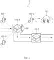
- FIG. 1 illustrates a battery production system according to various embodiments.
- a battery production system 1 may include at least one trays 110-1 and 110-2, a plurality of collectors 120-1, 120-2, and 120-3, and a server 130.
- the trays 110-1 and 110-2 may move along a conveyor belt while containing a battery.
- the tray 110-1 including the battery collides with a stopper 150 of the conveyor belt or collision occurs between the trays 110-1 and 110-2 due to logistics congestion, the quality and performance of the battery may be deteriorated due to a crack occurring in the battery (or a pouch including the battery), such that positions and impact occurrence of the trays 110-1 and 110-2 need to be monitored in real time.
- the plurality of collectors 120-1, 120-2, and 120-3 may be disposed at a distance spaced from each conveyor belt and may wirelessly transmit and receive a signal to and from the trays 110-1 and 110-2.
- Each of the plurality of collectors 120-1, 120-2, and 120-3 may measure distances to the trays 110-1 and 110-2 through wireless communication with the trays 110-1 and 110-2, and may receive information related to impact (e.g., impact amount information) from the trays 110-1 and 110-2.
- a wireless communication method between the plurality of collectors 120-1, 120-2, and 120-3 and the trays 110-1 and 110-2 may vary, and for example, to improve positioning accuracy, an ultra wide band (UWB) signal may be used.
- UWB ultra wide band
- the server 130 may be configured to monitor in real time the positions and impact occurrence of the trays 110-1 and 110-2 based on information received from the plurality of collectors 120-1, 120-2, and 120-3, and to accumulate and use the monitored data. For example, the server 130 may calculate the position of the tray 110-1 by using various positioning methods for a distance of each of the plurality of collectors 120-1, 120-2, and 120-3 to the tray 110-1. The positioning method may include, for example, a triangulation method. The server 130 may determine whether impact occurs in the tray 110-1, based on the impact amount information of the tray 110-1 received from the plurality of collectors 120-1, 120-2, and 120-3.
- the server 130 may accumulate data related to impact occurrence (e.g., position, time, and frequency of impact occurrence, etc.) to allow a user to recognize a reason for impact occurrence and to cure the same, and output a notification immediately upon determining that the impact occurs, to allow the user to quickly detect a defective battery occurring in a logistics movement process.
- the server 130 may notify the user of a battery suspected of being defective by using a designated method (e.g., lighting or alarm) when the tray 110 reaches a final point of the conveyor belt.
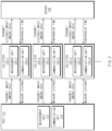
- FIG. 2 is a block diagram of a battery production system according to various embodiments.
- the tray 110 may include a measurement unit 112 and a communication unit 114.
- the tray 110 may further include a power source unit (e.g., a battery) that supplies power to implement the measurement unit 112 and the communication unit 114.
- the measurement unit 112 may be configured to obtain data for calculating the amount of impact occurring during movement of the tray 110.
- the 'measurement unit' may also be referred to as a 'measurement device', a 'measurement module', a 'measurement circuit', or a 'sensor'.
- the measurement unit 112 may include at least one of an acceleration sensor or a gyro sensor (an angular velocity sensor).
- the acceleration sensor may sense an acceleration in x, y, and z axes, and the gyro sensor may sense an angular velocity.
- the communication unit 114 may be configured to perform wireless communication with the plurality of collectors 120-1, 120-2, and 120-3.
- the 'communication unit' may also be referred to as a 'communication device', a 'communication module', a 'communication circuit', or a 'modem'.
- the communication unit 114 may support a UWB communication protocol, without being limited thereto.
- each of the measurement unit 112 and the communication unit 114 may perform an operation at designated intervals.
- the measurement unit 112 may measure an acceleration or an angular velocity at designated measurement intervals, and the communication unit 114 may transmit a signal to the collectors 120-1, 120-2, and 120-3 at designated communication intervals.
- the tray 110 may adjust a measurement interval of the measurement unit 112 and a communication interval and a signal strength of the communication unit 114 to improve the precision of impact amount calculation and accurately provide a position of the tray 110.
- FIGS. 3 to 5 A detailed embodiment related to adjustment of the measurement interval, the communication interval, and the signal strength will be described with reference to FIGS. 3 to 5 .
- the plurality of collectors 120-1, 120-2, and 120-3 may respectively include measurement units 122-1, 122-2, and 122-3, and communication units 124-1, 124-2, and 124-3.
- the plurality of collectors 120-1, 120-2, and 120-3 may further include a power source unit (e.g., a battery) that supplies power to implement the measurement units 122-1, 122-2, and 122-3, and the communication units 124-1, 124-2, and 124-3.
- the communication units 124-1, 124-2, and 124-3 may be configured to perform wireless communication (e.g., UWB) with the communication unit 114 of the tray 110.
- the measurement units 122-1, 122-2, and 122-3 may calculate a distance to the tray 110 based on a wireless communication result.
- the communication unit 124-1 of the collector 120-1 may transmit a signal to the communication unit 114 of the tray 110 and the receive a signal from the communication unit 114.
- the measurement unit 122-1 of the collector 120-1 may calculate a distance between the collector 120-1 and the tray 110 by using a round-trip time of a signal.
- the communication unit 124-1 of the collector 120-1 may receive data related to an impact time (e.g., an acceleration and an angular velocity) from the try 110 through a signal for distance measurement or a signal that is separate from the signal.
- the communication units 124-1, 124-2, and 124-3 of the plurality of collectors 120-1, 120-2, and 120-3 may transmit information related to the tray 110, e.g., at least one of distance information and impact amount information to the server 130.
- the server 130 may track in real time the positions and impact occurrence of the tray 110-1 based on information received from the plurality of collectors 120-1, 120-2, and 120-3. According to an embodiment, the server 130 may transmit a signal for time synchronization to the plurality of collectors 120-1, 120-2, and 120-3 at designated intervals to improve the accuracy of position calculation based on a triangulation method.
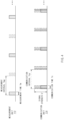
- FIGS. 3 through 5 illustrate a measurement interval and a communication interval according to various embodiments.
- FIG. 3 shows a measurement interval and a communication interval before sensing of impact in the tray 110
- FIG. 4 shows a measurement interval and a communication interval after sensing of impact in the tray 110.
- a horizontal axis indicates time.
- the measurement unit 112 may perform measurement for impact sensing at designated measurement intervals Tmp and in a designated measurement time Tm.
- the communication unit 114 may perform wireless communication with a collector at designated communication intervals Tcp and in a designated communication time Tc. For example, when data related to impact is generated by the measurement unit 112, the communication unit 114 may transmit data received from the measurement unit 112 to at least one collector (e.g., 120-1).
- the communication unit 114 may transmit a signal at a designated signal strength S.
- a signal for distance measurement and a signal for impact data transmission may be identical or separate signals.
- the tray 110 may change a measurement interval of the measurement unit 112 and a communication interval 114 of the communication unit 114 in response to sensing of impact. For example, when data (e.g., an acceleration or an angular velocity) measured in a previous measurement time exceeds a threshold value, the measurement unit 112 may perform measurement at measurement intervals Tmp' reduced at a designated first rate from the measurement intervals Tmp to improve measurement accuracy.
- the communication unit 114 may also perform wireless communication at communication intervals Tcp' reduced at a designated second rate from the communication intervals Tcp based on data (i.e., an acceleration or an angular velocity exceeding the threshold value) received from the measurement unit 112 to more frequently transmit the data to the collector 120-1.
- the second rate may be equal to or different from the first rate.
- the collector 120-1 may more precisely measure a distance between the tray 110 and the collector 120-1.
- the collector 120-1 may reduce the communication intervals of the communication unit 124-1 to more frequently transmit the impact amount data of the tray 110 to the server 130.
- the communication unit 114 may increase a signal strength at a designated third rate.
- the third rate may be equal to or different from the first rate or the second rate.
- the collector 120-1 may sense occurrence of impact in the tray 110 by receiving a signal of an increased strength even though failing to receive separate impact amount data.
- the server 130 located farther than the collector 120-1 may also receive the signal of the communication unit 114, such that the server 130 may quickly sense occurrence of impact.
- FIG. 5 shows an example where a measurement interval, a communication interval, and a signal strength are controlled.
- a first graph 501 indicates a value before impact is sensed in the tray 110
- a second graph 502 indicates a value after impact is sensed in the tray 110.
- the measurement unit 112 may reduce a measurement interval to 1/2 and the communication unit 114 may reduce a communication interval to 1/2.
- the communication unit 114 may double a signal strength.
- FIG. 6 is an operating flowchart of a tray to control a measurement interval and a communication interval, according to various embodiments.
- the measurement unit 112 of the tray 110 may sense occurrence of impact at designated measurement intervals.
- the measurement unit 112 may measure an acceleration or an angular velocity.
- the communication unit 114 of the tray 110 may perform wireless communication with the plurality of collectors 120-1, 120-2, and 120-3 at designated communication intervals.
- the measurement unit 112 may sense impact in the tray 110. For example, the measurement unit 112 may determine that the impact occurs when the measured acceleration or angular velocity exceeds a threshold value. When the measured data does not exceed the threshold value, the measurement unit 112 and the communication unit 114 may repeat operations 610 and 620.
- the measurement unit 112 may reduce a measurement interval at a designated first rate in operation 640.
- the communication unit 114 may reduce a communication interval at a designated second rate.
- the communication unit 114 may further perform operation 660. More specifically, the communication unit 114 may increase a signal strength at a designated third rate.
- FIG. 7 is an operating flowchart of a collector to transmit information about a tray, according to various embodiments.
- a collector e.g., 120-1
- the collector 120-1 may measure a distance to the tray 110 based on a wireless communication result. For example, the collector 120-1 may measure the distance by using round-trip times of a transmission signal and a received signal.
- the collector 120-1 may determine whether impact occurs in the tray 110. For example, the collector 120-1 may determine that the impact occurs in the tray 110 when data (e.g., an acceleration or an angular velocity) received from the tray 110 exceeds a threshold value or a strength of a signal received from the tray 110 exceeds a threshold value.
- data e.g., an acceleration or an angular velocity
- the collector 120-1 may transmit the distance to the tray 110 and information about occurrence of impact of the tray 110 to the server 130.
Landscapes
- Engineering & Computer Science (AREA)
- Physics & Mathematics (AREA)
- General Physics & Mathematics (AREA)
- Business, Economics & Management (AREA)
- Computer Networks & Wireless Communication (AREA)
- Radar, Positioning & Navigation (AREA)
- Remote Sensing (AREA)
- Economics (AREA)
- Signal Processing (AREA)
- Human Resources & Organizations (AREA)
- Strategic Management (AREA)
- General Business, Economics & Management (AREA)
- Tourism & Hospitality (AREA)
- Theoretical Computer Science (AREA)
- Marketing (AREA)
- Entrepreneurship & Innovation (AREA)
- Development Economics (AREA)
- Quality & Reliability (AREA)
- Operations Research (AREA)
- Chemical & Material Sciences (AREA)
- Health & Medical Sciences (AREA)
- Electrochemistry (AREA)
- Chemical Kinetics & Catalysis (AREA)
- Manufacturing & Machinery (AREA)
- General Health & Medical Sciences (AREA)
- Primary Health Care (AREA)
- General Chemical & Material Sciences (AREA)
- Details Of Rigid Or Semi-Rigid Containers (AREA)
- Management, Administration, Business Operations System, And Electronic Commerce (AREA)
- Arrangements For Transmission Of Measured Signals (AREA)
- Accounting & Taxation (AREA)
- Finance (AREA)
- Educational Administration (AREA)
- Game Theory and Decision Science (AREA)
Abstract
Description
- This application claims priority to and the benefit of Korean Patent Application No.
10-2021-0120044 filed in the Korean Intellectual Property Office on September 8, 2021 - Embodiments disclosed herein relate to a battery production system and management thereof.
- Recently, research and development of secondary batteries have been actively performed. Herein, the secondary batteries, which are chargeable/dischargeable batteries, may include all of conventional nickel (Ni)/cadmium (Cd) batteries, Ni/metal hydride (MH) batteries, etc., and recent lithium-ion batteries. Among the secondary batteries, a lithium-ion battery has a much higher energy density than those of the conventional Ni/Cd batteries, Ni/MH batteries, etc. Moreover, the lithium-ion battery may be manufactured to be small and lightweight, such that the lithium-ion battery has been used as a power source of mobile devices. In addition, the lithium ion battery is attracting attention as a next-generation energy storage medium as a usage range thereof is expanded to a power source of electric vehicles.
- In a battery production system, a battery is moved through a conveyor belt while being carried on a tray, and may be damaged for various reasons in a logistics movement process. For example, when logistics are congested in a specific section of the conveyor belt, cracks may occur due to collisions between logistics, leading to deterioration of battery product quality. Thus, proactive or follow-up management of product quality deterioration occurring in logistics movement in a battery production system is required.
- Technical problems of the embodiments disclosed herein are not limited to the above-described technical problems, and other unmentioned technical problems would be clearly understood by one of ordinary skill in the art from the following description.
- A battery production system disclosed herein includes a tray including a battery, a plurality of collectors configured to perform wireless communication with the tray, and a server configured to track a position of the tray and whether an impact occurs in the tray based on information received from the plurality of collectors, in which the tray includes a measurement unit configured to sense an impact and a communication unit configured to perform wireless communication with the plurality of collectors, the measurement unit is configured to reduce a measurement interval at a designated first rate upon sensing the impact, and the communication unit is configured to reduce an interval of the wireless communication at a designated second rate upon sensing the impact.
- An operating method of a battery production system disclosed herein includes operations of sensing, by a tray, whether an impact occurs at designated measurement intervals, performing, by the tray, wireless communication with a plurality of collectors, upon sensing the impact, reducing, by the tray, a measurement interval at a designated first rate and reducing an interval of the wireless communication at a designated second rate, transmitting, by the plurality of collectors, a result of the wireless communication with the tray to a server, and determining, by the server, a position of the tray and whether an impact occurs in the tray based on information received from the plurality of collectors.
- A battery production system according to an embodiment disclosed herein may check in advance factors of battery product quality deterioration occurring in logistics movement by tracking in real time a position and impact occurrence of a tray.
- The battery production system according to an embodiment disclosed herein may manage a congestion section and minimize a loss by monitoring in real time logistics movement of a battery.
- The battery production system according to an embodiment disclosed herein may more precisely track data related to a battery suspected of being defective in a monitoring process.
- The battery management apparatus according to an embodiment disclosed herein may reduce a cost for detecting and managing a low-performance battery.
-
-
FIG. 1 illustrates a battery production system according to various embodiments. -
FIG. 2 is a block diagram of a battery production system according to various embodiments. -
FIG. 3 illustrates a measurement interval and a communication interval according to various embodiments. -
FIG. 4 illustrates a measurement interval and a communication interval according to various embodiments. -
FIG. 5 illustrates a measurement interval and a communication interval according to various embodiments. -
FIG. 6 is an operating flowchart of a tray to control a measurement interval and a communication interval, according to various embodiments. -
FIG. 7 is an operating flowchart of a collector to transmit information about a tray, according to various embodiments. - Hereinafter, various embodiments disclosed herein will be described in detail with reference to the accompanying drawings. In this document, identical reference numerals will be used for identical components in the drawings, and the identical components will not be redundantly described.
- For various embodiments disclosed herein, specific structural or functional descriptions are only exemplified for the purpose of describing the embodiments, and various embodiments disclosed herein may be implemented in various forms, and should not be construed as being limited to the embodiments described herein.
- As used in various embodiments, the terms "1st, "2nd", "first", "second", or the like may modify various components regardless of importance, and do not limit the components. For example, a first component may be named as a second component without departing from the right scope of an embodiment disclosed herein, and similarly, the second component may be named as the first component.
- Terms used in the present document are used for only describing a specific exemplary embodiment of the disclosure and may not have an intention to limit the scope of other exemplary embodiments of the disclosure. It is to be understood that the singular forms include plural references unless the context clearly dictates otherwise.
- All terms including technical and scientific terms used herein have the same meaning as commonly understood by one of ordinary skill in the art to which the embodiments disclosed herein belong. It will be further understood that terms, such as those defined in commonly used dictionaries, should be interpreted as having a meaning that is consistent with their meaning in the context of the relevant art and will not be interpreted in an idealized or overly formal sense unless expressly so defined herein. In some cases, the terms defined herein may be interpreted to exclude embodiments disclosed herein.
-
FIG. 1 illustrates a battery production system according to various embodiments. - Referring to
FIG. 1 , abattery production system 1 may include at least one trays 110-1 and 110-2, a plurality of collectors 120-1, 120-2, and 120-3, and aserver 130. - The trays 110-1 and 110-2 may move along a conveyor belt while containing a battery. When the tray 110-1 including the battery collides with a
stopper 150 of the conveyor belt or collision occurs between the trays 110-1 and 110-2 due to logistics congestion, the quality and performance of the battery may be deteriorated due to a crack occurring in the battery (or a pouch including the battery), such that positions and impact occurrence of the trays 110-1 and 110-2 need to be monitored in real time. - The plurality of collectors 120-1, 120-2, and 120-3 may be disposed at a distance spaced from each conveyor belt and may wirelessly transmit and receive a signal to and from the trays 110-1 and 110-2. Each of the plurality of collectors 120-1, 120-2, and 120-3 may measure distances to the trays 110-1 and 110-2 through wireless communication with the trays 110-1 and 110-2, and may receive information related to impact (e.g., impact amount information) from the trays 110-1 and 110-2. In this case, a wireless communication method between the plurality of collectors 120-1, 120-2, and 120-3 and the trays 110-1 and 110-2 may vary, and for example, to improve positioning accuracy, an ultra wide band (UWB) signal may be used.
- The
server 130 may be configured to monitor in real time the positions and impact occurrence of the trays 110-1 and 110-2 based on information received from the plurality of collectors 120-1, 120-2, and 120-3, and to accumulate and use the monitored data. For example, theserver 130 may calculate the position of the tray 110-1 by using various positioning methods for a distance of each of the plurality of collectors 120-1, 120-2, and 120-3 to the tray 110-1. The positioning method may include, for example, a triangulation method. Theserver 130 may determine whether impact occurs in the tray 110-1, based on the impact amount information of the tray 110-1 received from the plurality of collectors 120-1, 120-2, and 120-3. Theserver 130 may accumulate data related to impact occurrence (e.g., position, time, and frequency of impact occurrence, etc.) to allow a user to recognize a reason for impact occurrence and to cure the same, and output a notification immediately upon determining that the impact occurs, to allow the user to quickly detect a defective battery occurring in a logistics movement process. Alternatively, when sensing impact occurrence in thetray 110, theserver 130 may notify the user of a battery suspected of being defective by using a designated method (e.g., lighting or alarm) when thetray 110 reaches a final point of the conveyor belt. -
FIG. 2 is a block diagram of a battery production system according to various embodiments. - Referring to
FIG. 2 , thetray 110 may include ameasurement unit 112 and acommunication unit 114. Although not shown inFIG. 2 , thetray 110 may further include a power source unit (e.g., a battery) that supplies power to implement themeasurement unit 112 and thecommunication unit 114. Themeasurement unit 112 may be configured to obtain data for calculating the amount of impact occurring during movement of thetray 110. The 'measurement unit' may also be referred to as a 'measurement device', a 'measurement module', a 'measurement circuit', or a 'sensor'. For example, themeasurement unit 112 may include at least one of an acceleration sensor or a gyro sensor (an angular velocity sensor). The acceleration sensor may sense an acceleration in x, y, and z axes, and the gyro sensor may sense an angular velocity. Thecommunication unit 114 may be configured to perform wireless communication with the plurality of collectors 120-1, 120-2, and 120-3. The 'communication unit' may also be referred to as a 'communication device', a 'communication module', a 'communication circuit', or a 'modem'. For example, thecommunication unit 114 may support a UWB communication protocol, without being limited thereto. - Due to the finitude of power supplied to the
measurement unit 112 and thecommunication unit 114, each of themeasurement unit 112 and thecommunication unit 114 may perform an operation at designated intervals. For example, themeasurement unit 112 may measure an acceleration or an angular velocity at designated measurement intervals, and thecommunication unit 114 may transmit a signal to the collectors 120-1, 120-2, and 120-3 at designated communication intervals. When impact is sensed in thetray 110 according to embodiments, thetray 110 may adjust a measurement interval of themeasurement unit 112 and a communication interval and a signal strength of thecommunication unit 114 to improve the precision of impact amount calculation and accurately provide a position of thetray 110. A detailed embodiment related to adjustment of the measurement interval, the communication interval, and the signal strength will be described with reference toFIGS. 3 to 5 . - The plurality of collectors 120-1, 120-2, and 120-3 may respectively include measurement units 122-1, 122-2, and 122-3, and communication units 124-1, 124-2, and 124-3. The plurality of collectors 120-1, 120-2, and 120-3 may further include a power source unit (e.g., a battery) that supplies power to implement the measurement units 122-1, 122-2, and 122-3, and the communication units 124-1, 124-2, and 124-3. The communication units 124-1, 124-2, and 124-3 may be configured to perform wireless communication (e.g., UWB) with the
communication unit 114 of thetray 110. The measurement units 122-1, 122-2, and 122-3 may calculate a distance to thetray 110 based on a wireless communication result. For example, the communication unit 124-1 of the collector 120-1 may transmit a signal to thecommunication unit 114 of thetray 110 and the receive a signal from thecommunication unit 114. The measurement unit 122-1 of the collector 120-1 may calculate a distance between the collector 120-1 and thetray 110 by using a round-trip time of a signal. The communication unit 124-1 of the collector 120-1 may receive data related to an impact time (e.g., an acceleration and an angular velocity) from thetry 110 through a signal for distance measurement or a signal that is separate from the signal. The communication units 124-1, 124-2, and 124-3 of the plurality of collectors 120-1, 120-2, and 120-3 may transmit information related to thetray 110, e.g., at least one of distance information and impact amount information to theserver 130. - The
server 130 may track in real time the positions and impact occurrence of the tray 110-1 based on information received from the plurality of collectors 120-1, 120-2, and 120-3. According to an embodiment, theserver 130 may transmit a signal for time synchronization to the plurality of collectors 120-1, 120-2, and 120-3 at designated intervals to improve the accuracy of position calculation based on a triangulation method. -
FIGS. 3 through 5 illustrate a measurement interval and a communication interval according to various embodiments. -
FIG. 3 shows a measurement interval and a communication interval before sensing of impact in thetray 110, andFIG. 4 shows a measurement interval and a communication interval after sensing of impact in thetray 110. In each drawing, a horizontal axis indicates time. - Referring to
FIG. 3 , themeasurement unit 112 may perform measurement for impact sensing at designated measurement intervals Tmp and in a designated measurement time Tm. Thecommunication unit 114 may perform wireless communication with a collector at designated communication intervals Tcp and in a designated communication time Tc. For example, when data related to impact is generated by themeasurement unit 112, thecommunication unit 114 may transmit data received from themeasurement unit 112 to at least one collector (e.g., 120-1). Thecommunication unit 114 may transmit a signal at a designated signal strength S. A signal for distance measurement and a signal for impact data transmission may be identical or separate signals. - Referring to
FIG. 4 , thetray 110 may change a measurement interval of themeasurement unit 112 and acommunication interval 114 of thecommunication unit 114 in response to sensing of impact. For example, when data (e.g., an acceleration or an angular velocity) measured in a previous measurement time exceeds a threshold value, themeasurement unit 112 may perform measurement at measurement intervals Tmp' reduced at a designated first rate from the measurement intervals Tmp to improve measurement accuracy. Thecommunication unit 114 may also perform wireless communication at communication intervals Tcp' reduced at a designated second rate from the communication intervals Tcp based on data (i.e., an acceleration or an angular velocity exceeding the threshold value) received from themeasurement unit 112 to more frequently transmit the data to the collector 120-1. The second rate may be equal to or different from the first rate. As the number of pieces of the data received from thetray 110 increases, the collector 120-1 may more precisely measure a distance between thetray 110 and the collector 120-1. Although not shown inFIG. 4 , when it is determined that the impact amount data received from thetray 110 exceeds the threshold value, the collector 120-1 may reduce the communication intervals of the communication unit 124-1 to more frequently transmit the impact amount data of thetray 110 to theserver 130. - According to an embodiment, the
communication unit 114 may increase a signal strength at a designated third rate. The third rate may be equal to or different from the first rate or the second rate. The collector 120-1 may sense occurrence of impact in thetray 110 by receiving a signal of an increased strength even though failing to receive separate impact amount data. Moreover, when the signal strength increases, not only the collector 120-1, but also theserver 130 located farther than the collector 120-1 may also receive the signal of thecommunication unit 114, such that theserver 130 may quickly sense occurrence of impact. -
FIG. 5 shows an example where a measurement interval, a communication interval, and a signal strength are controlled. For example, afirst graph 501 indicates a value before impact is sensed in thetray 110, and asecond graph 502 indicates a value after impact is sensed in thetray 110. When impact is sensed in thetray 110, themeasurement unit 112 may reduce a measurement interval to 1/2 and thecommunication unit 114 may reduce a communication interval to 1/2. Thecommunication unit 114 may double a signal strength. -
FIG. 6 is an operating flowchart of a tray to control a measurement interval and a communication interval, according to various embodiments. - Referring to
FIG. 6 , inoperation 610, themeasurement unit 112 of thetray 110 may sense occurrence of impact at designated measurement intervals. For example, themeasurement unit 112 may measure an acceleration or an angular velocity. - In
operation 620, thecommunication unit 114 of thetray 110 may perform wireless communication with the plurality of collectors 120-1, 120-2, and 120-3 at designated communication intervals. - In
operation 630, themeasurement unit 112 may sense impact in thetray 110. For example, themeasurement unit 112 may determine that the impact occurs when the measured acceleration or angular velocity exceeds a threshold value. When the measured data does not exceed the threshold value, themeasurement unit 112 and thecommunication unit 114 may repeatoperations - When the impact is sensed, the
measurement unit 112 may reduce a measurement interval at a designated first rate inoperation 640. Inoperation 650, thecommunication unit 114 may reduce a communication interval at a designated second rate. - According to an embodiment, the
communication unit 114 may further performoperation 660. More specifically, thecommunication unit 114 may increase a signal strength at a designated third rate. -
FIG. 7 is an operating flowchart of a collector to transmit information about a tray, according to various embodiments. - Referring to
FIG. 7 , inoperation 710, a collector (e.g., 120-1) may perform wireless communication with thetray 110. - In
operation 720, the collector 120-1 may measure a distance to thetray 110 based on a wireless communication result. For example, the collector 120-1 may measure the distance by using round-trip times of a transmission signal and a received signal. - In
operation 730, the collector 120-1 may determine whether impact occurs in thetray 110. For example, the collector 120-1 may determine that the impact occurs in thetray 110 when data (e.g., an acceleration or an angular velocity) received from thetray 110 exceeds a threshold value or a strength of a signal received from thetray 110 exceeds a threshold value. - In
operation 740, the collector 120-1 may transmit the distance to thetray 110 and information about occurrence of impact of thetray 110 to theserver 130. - Even though all components constituting an embodiment disclosed herein have been described above as being combined into one or operating in combination, the embodiments disclosed herein are not necessarily limited to the embodiments. That is, within the object scope of the embodiments disclosed herein, all the components may operate by being selectively combined into one or more.
- Moreover, terms such as "include", "constitute" or "have" described above may mean that the corresponding component may be inherent unless otherwise stated, and thus should be construed as further including other components rather than excluding other components. All terms including technical or scientific terms have the same meanings as those generally understood by those of ordinary skill in the art to which the embodiments disclosed herein pertain, unless defined otherwise. The terms used generally like terms defined in dictionaries should be interpreted as having meanings that are the same as the contextual meanings of the relevant technology and should not be interpreted as having ideal or excessively formal meanings unless they are clearly defined in the present document.
- The above description is merely illustrative of the technical idea of the present disclosure, and various modifications and variations will be possible without departing from the essential characteristics of embodiments of the present disclosure by those of ordinary skill in the art to which the embodiments disclosed herein pertains. Therefore, the embodiments disclosed herein are intended for description rather than limitation of the technical spirit of the embodiments disclosed herein and the scope of the technical spirit of the present disclosure is not limited by these embodiments disclosed herein. The protection scope of the technical spirit disclosed herein should be interpreted by the following claims, and all technical spirits within the same range should be understood to be included in the range of the present document.
Claims (14)
- A battery production system comprising:a tray comprising a battery;a plurality of collectors configured to perform wireless communication with the tray; anda server configured to track a position of the tray and whether an impact occurs in the tray based on information received from the plurality of collectors,wherein the tray comprisesa measurement unit configured to sense an impact and a communication unit configured to perform wireless communication with the plurality of collectors,the measurement unit is configured to reduce a measurement interval at a designated first rate upon sensing the impact, andthe communication unit is configured to reduce an interval of the wireless communication at a designated second rate upon sensing the impact.
- The battery production system of claim 1, wherein the measurement unit comprises at least one of an acceleration sensor or a gyro sensor, and
the communication unit is further configured to transmit impact amount information measured by the measurement unit to the plurality of collectors. - The battery production system of claim 2, wherein the plurality of collectors are configured to transmit a measured distance to the tray and the measured impact amount information to the server through the wireless communication.
- The battery production system of claim 2, wherein the plurality of collectors are configured to determine a distance to the tray based on transmission and reception times of an ultra wide band (UWB) signal.
- The battery production system of claim 3, wherein the server is further configured to determine the position and the impact occurrence of the tray based on the information received from the plurality of collectors.
- The battery production system of claim 5, wherein the server is further configured to calculate the position of the tray by using a distance between the plurality of collectors and the tray and a triangulation method.
- The battery production system of claim 1, wherein the communication unit is further configured to increase a strength of a signal for the wireless communication at a designated third rate upon sensing the impact.
- The battery production system of claim 7, wherein the plurality of collectors are further configured to determine that the impact occurs in the tray, upon receiving the signal of the increased strength from the tray.
- The battery production system of claim 7, wherein the server is further configured to determine that the impact occurs in the tray, upon receiving the signal of the increased strength from the tray.
- An operating method of a battery production system, the operating method comprising operations of:sensing, by a tray, whether an impact occurs at designated measurement intervals;performing, by the tray, wireless communication with a plurality of collectors;upon sensing the impact, reducing, by the tray, a measurement interval at a designated first rate and reducing an interval of the wireless communication at a designated second rate;transmitting, by the plurality of collectors, a result of the wireless communication with the tray to a server; anddetermining, by the server, a position of the tray and whether an impact occurs in the tray based on information received from the plurality of collectors.
- The operating method of claim 10, wherein the operation of transmitting, by the plurality of collectors, the result of the wireless communication with the tray to the server comprises an operation of transmitting a distance to the tray, measured based on times of transmission and reception of a UWB signal and impact amount information of the tray to the server.
- The operating method of claim 11, wherein the operation of determining, by the server, the position of the tray comprises an operation of determining the position of the tray by using a distance between the plurality of collectors and the tray and a triangulation method.
- The operating method of claim 10, further comprising an operation of increasing a strength of a signal for the wireless communication at a designated third rate upon sensing the impact.
- The operating method of claim 13, further comprising an operation of determining, by the plurality of collectors or the server, that the impact occurs in the tray, upon receiving the signal of the increased strength from the tray.
Applications Claiming Priority (2)
| Application Number | Priority Date | Filing Date | Title |
|---|---|---|---|
| KR1020210120044A KR20230036933A (en) | 2021-09-08 | 2021-09-08 | Battery production system and management method thereof |
| PCT/KR2022/011841 WO2023038305A1 (en) | 2021-09-08 | 2022-08-09 | Battery production system and management method therefor |
Publications (3)
| Publication Number | Publication Date |
|---|---|
| EP4246413A1 true EP4246413A1 (en) | 2023-09-20 |
| EP4246413A4 EP4246413A4 (en) | 2024-05-29 |
| EP4246413B1 EP4246413B1 (en) | 2024-11-27 |
Family
ID=85506714
Family Applications (1)
| Application Number | Title | Priority Date | Filing Date |
|---|---|---|---|
| EP22867574.0A Active EP4246413B1 (en) | 2021-09-08 | 2022-08-09 | Battery production system and management method therefor |
Country Status (9)
| Country | Link |
|---|---|
| US (1) | US12523675B2 (en) |
| EP (1) | EP4246413B1 (en) |
| JP (1) | JP7700407B2 (en) |
| KR (1) | KR20230036933A (en) |
| CN (1) | CN116762218A (en) |
| ES (1) | ES3012743T3 (en) |
| HU (1) | HUE070021T2 (en) |
| PL (1) | PL4246413T3 (en) |
| WO (1) | WO2023038305A1 (en) |
Family Cites Families (24)
| Publication number | Priority date | Publication date | Assignee | Title |
|---|---|---|---|---|
| JP2810633B2 (en) | 1994-11-04 | 1998-10-15 | 山一電機株式会社 | Impact measurement method in goods transportation |
| KR200418790Y1 (en) | 2006-01-23 | 2006-06-14 | 한국프라스틱 주식회사 | Chip embedded container |
| KR100719280B1 (en) * | 2006-09-01 | 2007-05-18 | 아주대학교산학협력단 | Method and system for setting dynamic monitoring cycle in wireless sensor network |
| KR101203890B1 (en) | 2009-02-23 | 2012-11-23 | 디씨티 주식회사 | Transferring system |
| KR101201335B1 (en) | 2010-09-27 | 2012-11-14 | 에너지움 주식회사 | Monorail type transfer apparatus |
| JP2012236690A (en) | 2011-05-12 | 2012-12-06 | Daifuku Co Ltd | Conveyor |
| KR101678526B1 (en) * | 2011-11-17 | 2016-11-23 | 삼성에스디아이 주식회사 | Battery system, method for controlling battery system and energy storage system including the same |
| JP6161792B2 (en) * | 2014-03-26 | 2017-07-12 | 株式会社日立製作所 | Communication device, communication system |
| JP2018132440A (en) | 2017-02-16 | 2018-08-23 | 住友重機械搬送システム株式会社 | Tray and inspection system for power storage device |
| KR102394574B1 (en) * | 2017-07-11 | 2022-05-04 | 현대자동차 주식회사 | System and method for smart tag monitoring |
| WO2019045043A1 (en) | 2017-09-01 | 2019-03-07 | 株式会社椿本チエイン | Abnormality-sensing system, abnormality-sensing device, abnormality-sensing method, computer program, and chain |
| JP2019152563A (en) * | 2018-03-05 | 2019-09-12 | 神栄テストマシナリー株式会社 | Impact detector |
| JP7062074B2 (en) | 2018-08-28 | 2022-05-02 | 富士フイルム株式会社 | Monitoring device and monitoring system |
| KR20200030818A (en) | 2018-09-13 | 2020-03-23 | 주식회사 엘지화학 | Battery cell transfer device and transfer method using the same |
| JP2020071629A (en) | 2018-10-31 | 2020-05-07 | キヤノン株式会社 | Article management system |
| KR102044931B1 (en) | 2018-11-20 | 2019-11-14 | 주식회사 알티자동화 | Real-time location information management device and method of transportation management system |
| KR102232884B1 (en) * | 2019-01-17 | 2021-03-29 | 한전원자력연료 주식회사 | Real-time operation information collection and vibration monitoring system of pilger apparatus and its method |
| KR102475986B1 (en) | 2019-01-17 | 2022-12-09 | 주식회사 엘지에너지솔루션 | Negative electrode active material for secondary battery, negative electrode including same and manufacturing method thereof |
| DE102019201183A1 (en) | 2019-01-30 | 2020-07-30 | Robert Bosch Gmbh | Conveyor unit for an anode circuit of a fuel cell system for conveying a gaseous medium |
| KR102178501B1 (en) * | 2019-09-05 | 2020-11-13 | 주식회사 가디언이엔지 | Location stracking system based on facilities and method thereof |
| KR102866740B1 (en) * | 2020-08-11 | 2025-09-29 | 주식회사 엘지에너지솔루션 | Battery module with imploved assembly and battery pack including the same |
| CN113013508B (en) * | 2021-01-29 | 2021-10-26 | 中南大学 | Intelligent scheduling and tracing system and method for power battery formation process |
| KR102900200B1 (en) * | 2021-07-19 | 2025-12-16 | 주식회사 엘지에너지솔루션 | System for monitoring congestion of formaion tray |
| KR20230076669A (en) * | 2021-11-24 | 2023-05-31 | 주식회사 엘지에너지솔루션 | Battery movement detection apparatus and battery monitoring system comprising the same |
-
2021
- 2021-09-08 KR KR1020210120044A patent/KR20230036933A/en active Pending
-
2022
- 2022-08-09 PL PL22867574.0T patent/PL4246413T3/en unknown
- 2022-08-09 ES ES22867574T patent/ES3012743T3/en active Active
- 2022-08-09 WO PCT/KR2022/011841 patent/WO2023038305A1/en not_active Ceased
- 2022-08-09 EP EP22867574.0A patent/EP4246413B1/en active Active
- 2022-08-09 CN CN202280009001.5A patent/CN116762218A/en active Pending
- 2022-08-09 HU HUE22867574A patent/HUE070021T2/en unknown
- 2022-08-09 JP JP2023535811A patent/JP7700407B2/en active Active
- 2022-08-09 US US18/270,950 patent/US12523675B2/en active Active
Also Published As
| Publication number | Publication date |
|---|---|
| EP4246413B1 (en) | 2024-11-27 |
| KR20230036933A (en) | 2023-03-15 |
| US20240053376A1 (en) | 2024-02-15 |
| WO2023038305A1 (en) | 2023-03-16 |
| US12523675B2 (en) | 2026-01-13 |
| JP7700407B2 (en) | 2025-07-01 |
| HUE070021T2 (en) | 2025-05-28 |
| CN116762218A (en) | 2023-09-15 |
| PL4246413T3 (en) | 2025-03-17 |
| ES3012743T3 (en) | 2025-04-10 |
| EP4246413A4 (en) | 2024-05-29 |
| JP2024500685A (en) | 2024-01-10 |
Similar Documents
| Publication | Publication Date | Title |
|---|---|---|
| US20240175928A1 (en) | Internet of things battery device | |
| Gomez-de-Gabriel et al. | Monitoring harness use in construction with BLE beacons | |
| EP3544323B1 (en) | Method for determining channel delay, positioning method, and related device | |
| US8254293B2 (en) | Methods and systems for location estimation | |
| EP3589038B1 (en) | Method and system for determining the position of a node | |
| CN103293513B (en) | System and method for positioning underground coal mine staff based on RSS (received signal strength) and TOA (time of arrival) complementation | |
| US20100026569A1 (en) | Method and apparatus for location detection using gps and wifi/wimax | |
| US20230071988A1 (en) | Personnel safety sensing | |
| Almansa et al. | Autocalibration of a mobile uwb localization system for ad-hoc multi-robot deployments in gnss-denied environments | |
| US20060268795A1 (en) | Wireless communication system, node position calculation method and node | |
| US20130324150A1 (en) | Location estimation apparatus and method | |
| EP4246413B1 (en) | Battery production system and management method therefor | |
| KR100882590B1 (en) | Position determination device and method | |
| US12255712B2 (en) | Communication device and method of operation | |
| CN114585082B (en) | A wireless positioning method, device and storage medium for power Internet of Things equipment | |
| US20210318383A1 (en) | Lifetime battery tracking using a wireless interface | |
| EP3794746B1 (en) | Wireless camera tracking system | |
| EP4317034A1 (en) | Battery movement detection device and battery monitoring system comprising same | |
| Savić et al. | WELOC: Localizing Equipment in Marinas using Ultrasound | |
| CN119168385B (en) | Rail transit rear-end collision risk assessment method and system | |
| US20250358591A1 (en) | Method and system for locating stationary objects in an underground environment | |
| Sharma et al. | A multi-cell UWB-IR localization system for robot navigation | |
| EP4531161A1 (en) | Battery tracking system | |
| JP2026082204A (en) | Battery tracking system | |
| RU2454000C1 (en) | Method of determining base station location |
Legal Events
| Date | Code | Title | Description |
|---|---|---|---|
| STAA | Information on the status of an ep patent application or granted ep patent |
Free format text: STATUS: THE INTERNATIONAL PUBLICATION HAS BEEN MADE |
|
| PUAI | Public reference made under article 153(3) epc to a published international application that has entered the european phase |
Free format text: ORIGINAL CODE: 0009012 |
|
| STAA | Information on the status of an ep patent application or granted ep patent |
Free format text: STATUS: REQUEST FOR EXAMINATION WAS MADE |
|
| 17P | Request for examination filed |
Effective date: 20230615 |
|
| AK | Designated contracting states |
Kind code of ref document: A1 Designated state(s): AL AT BE BG CH CY CZ DE DK EE ES FI FR GB GR HR HU IE IS IT LI LT LU LV MC MK MT NL NO PL PT RO RS SE SI SK SM TR |
|
| A4 | Supplementary search report drawn up and despatched |
Effective date: 20240502 |
|
| RIC1 | Information provided on ipc code assigned before grant |
Ipc: G01P 15/00 20060101ALI20240426BHEP Ipc: G01L 5/00 20060101ALI20240426BHEP Ipc: H04W 4/38 20180101ALI20240426BHEP Ipc: G06Q 10/06 20230101ALI20240426BHEP Ipc: G06Q 10/08 20230101ALI20240426BHEP Ipc: H01M 50/20 20210101ALI20240426BHEP Ipc: G06Q 50/04 20120101AFI20240426BHEP |
|
| GRAP | Despatch of communication of intention to grant a patent |
Free format text: ORIGINAL CODE: EPIDOSNIGR1 |
|
| STAA | Information on the status of an ep patent application or granted ep patent |
Free format text: STATUS: GRANT OF PATENT IS INTENDED |
|
| DAV | Request for validation of the european patent (deleted) | ||
| DAX | Request for extension of the european patent (deleted) | ||
| INTG | Intention to grant announced |
Effective date: 20240812 |
|
| GRAS | Grant fee paid |
Free format text: ORIGINAL CODE: EPIDOSNIGR3 |
|
| GRAA | (expected) grant |
Free format text: ORIGINAL CODE: 0009210 |
|
| STAA | Information on the status of an ep patent application or granted ep patent |
Free format text: STATUS: THE PATENT HAS BEEN GRANTED |
|
| P01 | Opt-out of the competence of the unified patent court (upc) registered |
Free format text: CASE NUMBER: APP_54729/2024 Effective date: 20241004 |
|
| AK | Designated contracting states |
Kind code of ref document: B1 Designated state(s): AL AT BE BG CH CY CZ DE DK EE ES FI FR GB GR HR HU IE IS IT LI LT LU LV MC MK MT NL NO PL PT RO RS SE SI SK SM TR |
|
| REG | Reference to a national code |
Ref country code: GB Ref legal event code: FG4D |
|
| REG | Reference to a national code |
Ref country code: CH Ref legal event code: EP |
|
| REG | Reference to a national code |
Ref country code: IE Ref legal event code: FG4D |
|
| REG | Reference to a national code |
Ref country code: DE Ref legal event code: R096 Ref document number: 602022008250 Country of ref document: DE |
|
| REG | Reference to a national code |
Ref country code: SE Ref legal event code: TRGR |
|
| REG | Reference to a national code |
Ref country code: LT Ref legal event code: MG9D |
|
| REG | Reference to a national code |
Ref country code: NL Ref legal event code: MP Effective date: 20241127 |
|
| REG | Reference to a national code |
Ref country code: ES Ref legal event code: FG2A Ref document number: 3012743 Country of ref document: ES Kind code of ref document: T3 Effective date: 20250410 |
|
| PG25 | Lapsed in a contracting state [announced via postgrant information from national office to epo] |
Ref country code: IS Free format text: LAPSE BECAUSE OF FAILURE TO SUBMIT A TRANSLATION OF THE DESCRIPTION OR TO PAY THE FEE WITHIN THE PRESCRIBED TIME-LIMIT Effective date: 20250327 Ref country code: HR Free format text: LAPSE BECAUSE OF FAILURE TO SUBMIT A TRANSLATION OF THE DESCRIPTION OR TO PAY THE FEE WITHIN THE PRESCRIBED TIME-LIMIT Effective date: 20241127 Ref country code: PT Free format text: LAPSE BECAUSE OF FAILURE TO SUBMIT A TRANSLATION OF THE DESCRIPTION OR TO PAY THE FEE WITHIN THE PRESCRIBED TIME-LIMIT Effective date: 20250327 |
|
| PG25 | Lapsed in a contracting state [announced via postgrant information from national office to epo] |
Ref country code: FI Free format text: LAPSE BECAUSE OF FAILURE TO SUBMIT A TRANSLATION OF THE DESCRIPTION OR TO PAY THE FEE WITHIN THE PRESCRIBED TIME-LIMIT Effective date: 20241127 Ref country code: NL Free format text: LAPSE BECAUSE OF FAILURE TO SUBMIT A TRANSLATION OF THE DESCRIPTION OR TO PAY THE FEE WITHIN THE PRESCRIBED TIME-LIMIT Effective date: 20241127 |
|
| REG | Reference to a national code |
Ref country code: AT Ref legal event code: MK05 Ref document number: 1746439 Country of ref document: AT Kind code of ref document: T Effective date: 20241127 |
|
| PG25 | Lapsed in a contracting state [announced via postgrant information from national office to epo] |
Ref country code: BG Free format text: LAPSE BECAUSE OF FAILURE TO SUBMIT A TRANSLATION OF THE DESCRIPTION OR TO PAY THE FEE WITHIN THE PRESCRIBED TIME-LIMIT Effective date: 20241127 |
|
| PG25 | Lapsed in a contracting state [announced via postgrant information from national office to epo] |
Ref country code: NO Free format text: LAPSE BECAUSE OF FAILURE TO SUBMIT A TRANSLATION OF THE DESCRIPTION OR TO PAY THE FEE WITHIN THE PRESCRIBED TIME-LIMIT Effective date: 20250227 |
|
| PG25 | Lapsed in a contracting state [announced via postgrant information from national office to epo] |
Ref country code: GR Free format text: LAPSE BECAUSE OF FAILURE TO SUBMIT A TRANSLATION OF THE DESCRIPTION OR TO PAY THE FEE WITHIN THE PRESCRIBED TIME-LIMIT Effective date: 20250228 Ref country code: LV Free format text: LAPSE BECAUSE OF FAILURE TO SUBMIT A TRANSLATION OF THE DESCRIPTION OR TO PAY THE FEE WITHIN THE PRESCRIBED TIME-LIMIT Effective date: 20241127 Ref country code: AT Free format text: LAPSE BECAUSE OF FAILURE TO SUBMIT A TRANSLATION OF THE DESCRIPTION OR TO PAY THE FEE WITHIN THE PRESCRIBED TIME-LIMIT Effective date: 20241127 |
|
| PG25 | Lapsed in a contracting state [announced via postgrant information from national office to epo] |
Ref country code: RS Free format text: LAPSE BECAUSE OF FAILURE TO SUBMIT A TRANSLATION OF THE DESCRIPTION OR TO PAY THE FEE WITHIN THE PRESCRIBED TIME-LIMIT Effective date: 20250227 |
|
| REG | Reference to a national code |
Ref country code: HU Ref legal event code: AG4A Ref document number: E070021 Country of ref document: HU |
|
| PG25 | Lapsed in a contracting state [announced via postgrant information from national office to epo] |
Ref country code: SM Free format text: LAPSE BECAUSE OF FAILURE TO SUBMIT A TRANSLATION OF THE DESCRIPTION OR TO PAY THE FEE WITHIN THE PRESCRIBED TIME-LIMIT Effective date: 20241127 |
|
| PG25 | Lapsed in a contracting state [announced via postgrant information from national office to epo] |
Ref country code: DK Free format text: LAPSE BECAUSE OF FAILURE TO SUBMIT A TRANSLATION OF THE DESCRIPTION OR TO PAY THE FEE WITHIN THE PRESCRIBED TIME-LIMIT Effective date: 20241127 |
|
| PGFP | Annual fee paid to national office [announced via postgrant information from national office to epo] |
Ref country code: BE Payment date: 20250407 Year of fee payment: 4 |
|
| PG25 | Lapsed in a contracting state [announced via postgrant information from national office to epo] |
Ref country code: EE Free format text: LAPSE BECAUSE OF FAILURE TO SUBMIT A TRANSLATION OF THE DESCRIPTION OR TO PAY THE FEE WITHIN THE PRESCRIBED TIME-LIMIT Effective date: 20241127 |
|
| PG25 | Lapsed in a contracting state [announced via postgrant information from national office to epo] |
Ref country code: RO Free format text: LAPSE BECAUSE OF FAILURE TO SUBMIT A TRANSLATION OF THE DESCRIPTION OR TO PAY THE FEE WITHIN THE PRESCRIBED TIME-LIMIT Effective date: 20241127 |
|
| PG25 | Lapsed in a contracting state [announced via postgrant information from national office to epo] |
Ref country code: SK Free format text: LAPSE BECAUSE OF FAILURE TO SUBMIT A TRANSLATION OF THE DESCRIPTION OR TO PAY THE FEE WITHIN THE PRESCRIBED TIME-LIMIT Effective date: 20241127 |
|
| PG25 | Lapsed in a contracting state [announced via postgrant information from national office to epo] |
Ref country code: CZ Free format text: LAPSE BECAUSE OF FAILURE TO SUBMIT A TRANSLATION OF THE DESCRIPTION OR TO PAY THE FEE WITHIN THE PRESCRIBED TIME-LIMIT Effective date: 20241127 |
|
| PG25 | Lapsed in a contracting state [announced via postgrant information from national office to epo] |
Ref country code: IT Free format text: LAPSE BECAUSE OF FAILURE TO SUBMIT A TRANSLATION OF THE DESCRIPTION OR TO PAY THE FEE WITHIN THE PRESCRIBED TIME-LIMIT Effective date: 20241127 |
|
| REG | Reference to a national code |
Ref country code: DE Ref legal event code: R097 Ref document number: 602022008250 Country of ref document: DE |
|
| PGFP | Annual fee paid to national office [announced via postgrant information from national office to epo] |
Ref country code: HU Payment date: 20250827 Year of fee payment: 4 |
|
| PLBE | No opposition filed within time limit |
Free format text: ORIGINAL CODE: 0009261 |
|
| STAA | Information on the status of an ep patent application or granted ep patent |
Free format text: STATUS: NO OPPOSITION FILED WITHIN TIME LIMIT |
|
| REG | Reference to a national code |
Ref country code: CH Ref legal event code: L10 Free format text: ST27 STATUS EVENT CODE: U-0-0-L10-L00 (AS PROVIDED BY THE NATIONAL OFFICE) Effective date: 20251008 |
|
| PGFP | Annual fee paid to national office [announced via postgrant information from national office to epo] |
Ref country code: ES Payment date: 20250911 Year of fee payment: 4 |
|
| PGFP | Annual fee paid to national office [announced via postgrant information from national office to epo] |
Ref country code: DE Payment date: 20250721 Year of fee payment: 4 |
|
| PGFP | Annual fee paid to national office [announced via postgrant information from national office to epo] |
Ref country code: PL Payment date: 20250723 Year of fee payment: 4 |
|
| PGFP | Annual fee paid to national office [announced via postgrant information from national office to epo] |
Ref country code: FR Payment date: 20250725 Year of fee payment: 4 |
|
| PGFP | Annual fee paid to national office [announced via postgrant information from national office to epo] |
Ref country code: SE Payment date: 20250722 Year of fee payment: 4 |
|
| 26N | No opposition filed |
Effective date: 20250828 |
|
| REG | Reference to a national code |
Ref country code: CH Ref legal event code: H13 Free format text: ST27 STATUS EVENT CODE: U-0-0-H10-H13 (AS PROVIDED BY THE NATIONAL OFFICE) Effective date: 20260324 |
|
| PG25 | Lapsed in a contracting state [announced via postgrant information from national office to epo] |
Ref country code: MC Free format text: LAPSE BECAUSE OF FAILURE TO SUBMIT A TRANSLATION OF THE DESCRIPTION OR TO PAY THE FEE WITHIN THE PRESCRIBED TIME-LIMIT Effective date: 20241127 |
|
| PG25 | Lapsed in a contracting state [announced via postgrant information from national office to epo] |
Ref country code: LU Free format text: LAPSE BECAUSE OF NON-PAYMENT OF DUE FEES Effective date: 20250809 |
|
| PG25 | Lapsed in a contracting state [announced via postgrant information from national office to epo] |
Ref country code: CH Free format text: LAPSE BECAUSE OF NON-PAYMENT OF DUE FEES Effective date: 20250831 |