EP4246000A1 - Piston cylinder unit, set comprising a piston-cylinder unit and a group of piston-cylinder units - Google Patents
Piston cylinder unit, set comprising a piston-cylinder unit and a group of piston-cylinder units Download PDFInfo
- Publication number
- EP4246000A1 EP4246000A1 EP22162782.1A EP22162782A EP4246000A1 EP 4246000 A1 EP4246000 A1 EP 4246000A1 EP 22162782 A EP22162782 A EP 22162782A EP 4246000 A1 EP4246000 A1 EP 4246000A1
- Authority
- EP
- European Patent Office
- Prior art keywords
- piston
- movement sensor
- cylinder
- transverse bore
- housing
- Prior art date
- Legal status (The legal status is an assumption and is not a legal conclusion. Google has not performed a legal analysis and makes no representation as to the accuracy of the status listed.)
- Pending
Links
- 230000033001 locomotion Effects 0.000 claims abstract description 132
- 238000007789 sealing Methods 0.000 claims description 18
- 238000010276 construction Methods 0.000 abstract description 2
- 239000012530 fluid Substances 0.000 description 13
- 238000004519 manufacturing process Methods 0.000 description 6
- 239000000463 material Substances 0.000 description 6
- 238000005259 measurement Methods 0.000 description 5
- 238000009434 installation Methods 0.000 description 4
- 230000005855 radiation Effects 0.000 description 4
- 239000011324 bead Substances 0.000 description 3
- 230000008901 benefit Effects 0.000 description 3
- 230000005540 biological transmission Effects 0.000 description 3
- -1 polytetrafluoroethylene Polymers 0.000 description 3
- 230000007547 defect Effects 0.000 description 2
- 238000011161 development Methods 0.000 description 2
- 230000018109 developmental process Effects 0.000 description 2
- 238000005516 engineering process Methods 0.000 description 2
- 238000012423 maintenance Methods 0.000 description 2
- 239000004698 Polyethylene Substances 0.000 description 1
- 239000004743 Polypropylene Substances 0.000 description 1
- 108010001267 Protein Subunits Proteins 0.000 description 1
- 230000006978 adaptation Effects 0.000 description 1
- 238000004026 adhesive bonding Methods 0.000 description 1
- 230000002457 bidirectional effect Effects 0.000 description 1
- 239000000919 ceramic Substances 0.000 description 1
- 230000008859 change Effects 0.000 description 1
- 238000004140 cleaning Methods 0.000 description 1
- 230000001186 cumulative effect Effects 0.000 description 1
- 230000001419 dependent effect Effects 0.000 description 1
- 238000013461 design Methods 0.000 description 1
- 238000005553 drilling Methods 0.000 description 1
- 230000000694 effects Effects 0.000 description 1
- 238000011156 evaluation Methods 0.000 description 1
- 230000006872 improvement Effects 0.000 description 1
- 238000003780 insertion Methods 0.000 description 1
- 230000037431 insertion Effects 0.000 description 1
- 238000011089 mechanical engineering Methods 0.000 description 1
- 239000002184 metal Substances 0.000 description 1
- 230000003287 optical effect Effects 0.000 description 1
- 239000004033 plastic Substances 0.000 description 1
- 229920003023 plastic Polymers 0.000 description 1
- 229920000573 polyethylene Polymers 0.000 description 1
- 229920001155 polypropylene Polymers 0.000 description 1
- 229920001343 polytetrafluoroethylene Polymers 0.000 description 1
- 239000004810 polytetrafluoroethylene Substances 0.000 description 1
- 238000003825 pressing Methods 0.000 description 1
- 230000008439 repair process Effects 0.000 description 1
- 239000011343 solid material Substances 0.000 description 1
- 238000003860 storage Methods 0.000 description 1
Images


Classifications
-
- F—MECHANICAL ENGINEERING; LIGHTING; HEATING; WEAPONS; BLASTING
- F15—FLUID-PRESSURE ACTUATORS; HYDRAULICS OR PNEUMATICS IN GENERAL
- F15B—SYSTEMS ACTING BY MEANS OF FLUIDS IN GENERAL; FLUID-PRESSURE ACTUATORS, e.g. SERVOMOTORS; DETAILS OF FLUID-PRESSURE SYSTEMS, NOT OTHERWISE PROVIDED FOR
- F15B15/00—Fluid-actuated devices for displacing a member from one position to another; Gearing associated therewith
- F15B15/20—Other details, e.g. assembly with regulating devices
- F15B15/28—Means for indicating the position, e.g. end of stroke
- F15B15/2815—Position sensing, i.e. means for continuous measurement of position, e.g. LVDT
- F15B15/2869—Position sensing, i.e. means for continuous measurement of position, e.g. LVDT using electromagnetic radiation, e.g. radar or microwaves
-
- F—MECHANICAL ENGINEERING; LIGHTING; HEATING; WEAPONS; BLASTING
- F15—FLUID-PRESSURE ACTUATORS; HYDRAULICS OR PNEUMATICS IN GENERAL
- F15B—SYSTEMS ACTING BY MEANS OF FLUIDS IN GENERAL; FLUID-PRESSURE ACTUATORS, e.g. SERVOMOTORS; DETAILS OF FLUID-PRESSURE SYSTEMS, NOT OTHERWISE PROVIDED FOR
- F15B15/00—Fluid-actuated devices for displacing a member from one position to another; Gearing associated therewith
- F15B15/20—Other details, e.g. assembly with regulating devices
- F15B15/28—Means for indicating the position, e.g. end of stroke
- F15B15/2892—Means for indicating the position, e.g. end of stroke characterised by the attachment means
-
- F—MECHANICAL ENGINEERING; LIGHTING; HEATING; WEAPONS; BLASTING
- F15—FLUID-PRESSURE ACTUATORS; HYDRAULICS OR PNEUMATICS IN GENERAL
- F15B—SYSTEMS ACTING BY MEANS OF FLUIDS IN GENERAL; FLUID-PRESSURE ACTUATORS, e.g. SERVOMOTORS; DETAILS OF FLUID-PRESSURE SYSTEMS, NOT OTHERWISE PROVIDED FOR
- F15B21/00—Common features of fluid actuator systems; Fluid-pressure actuator systems or details thereof, not covered by any other group of this subclass
- F15B21/003—Systems with different interchangeable components, e.g. using preassembled kits
-
- F—MECHANICAL ENGINEERING; LIGHTING; HEATING; WEAPONS; BLASTING
- F15—FLUID-PRESSURE ACTUATORS; HYDRAULICS OR PNEUMATICS IN GENERAL
- F15B—SYSTEMS ACTING BY MEANS OF FLUIDS IN GENERAL; FLUID-PRESSURE ACTUATORS, e.g. SERVOMOTORS; DETAILS OF FLUID-PRESSURE SYSTEMS, NOT OTHERWISE PROVIDED FOR
- F15B15/00—Fluid-actuated devices for displacing a member from one position to another; Gearing associated therewith
- F15B15/08—Characterised by the construction of the motor unit
- F15B15/14—Characterised by the construction of the motor unit of the straight-cylinder type
- F15B15/1423—Component parts; Constructional details
- F15B15/1433—End caps
Definitions
- the present invention relates to a piston-cylinder unit.
- the piston-cylinder unit can be used in a known manner in a work machine (in particular a construction machine, an agricultural machine, a maritime machine, a wheel loader, an excavator, a tipper, a crane, a forklift, a lifting platform or another work machine found in mechanical engineering).
- the piston-cylinder unit can be used, for example, to steer, support, push out, tilt, lift, lower or otherwise move a part of the work machine (in particular a tool, a rocker arm or another part of the work machine). It is preferably a hydraulic piston-cylinder unit.
- the invention relates to a set with a piston-cylinder unit, whereby this set can also be used for a work machine.
- the invention relates to a group of piston-cylinder units, the group having different subgroups and the piston-cylinder units of the different subgroups being designed and intended for different purposes.
- a group of piston-cylinder units can, for example, be manufactured, offered and sold by a manufacturer for different purposes, or offered and sold by a sales company, or stored and/or used by a customer for different purposes.
- a generic piston-cylinder unit is from the publication DE 10 2019 122 121 A1 known.
- This well-known piston-cylinder unit is in Fig. 1 shown.
- Fig. 1 is shown by means of break lines that the piston-cylinder unit 1 can actually be longer and only part of it is shown.
- the piston-cylinder unit 1 has a cylinder 2 with a cylinder tube 31, an interior 3 and a cylinder head 4.
- the cylinder tube 31 is connected to the cylinder head 4 via a weld seam 23.
- a bearing bush 5 is arranged in the area of the cylinder head 4.
- DE 10 2019 122 121 A1 it is a hydraulic piston-cylinder unit 1, so that the interior 3 is filled with a hydraulic fluid 29, in particular oil.
- the cylinder 2 has a connection 6 and a connection 24.
- a hydraulic circuit, not shown here, with a hydraulic pump and changeover valves is connected to the connections 6, 24.
- the connections 6, 24 each open into an associated pressure chamber 32, 33.
- the pressure chambers 32, 33 are formed in the interior 3 and separated from one another by a piston 7.
- the piston 7 can be moved along the longitudinal central axis 30 of the cylinder 2 while sealing the pressure chambers 32, 33.
- an actuating force can be generated hydraulically in both directions along the longitudinal central axis 30, which acts on the piston 7, and with the thereby generated actuating movement of the piston 7, a change in the volume of the pressure chambers 32 , 33 can be brought about.
- the piston 7 shows the position of the piston 7 moved all the way to the right, ie the retracted position of the piston-cylinder unit 1.
- the piston 7 is connected to a piston rod 8, at the outer end of which a piston rod eye 9 is arranged.
- the piston rod eye 9 also has a bearing bush 10.
- the bearing bushes 5, 10 serve to link the piston-cylinder unit 1 to the parts of the work machine that are to be moved relative to one another by means of the piston-cylinder unit 1 and/or on which the piston-cylinder unit 1 exerts a force should.
- the piston rod 8 is mounted in a translationally movable manner in the axial direction along the longitudinal central axis 30 by means of a guide bushing 11.
- a rod seal 12, an O-ring 13 and a support ring 14 are provided for storage and sealing.
- the piston 7 is arranged non-rotatably on the piston rod 8 and secured by means of a lock nut 18. Furthermore, an O-ring 19, a piston guide ring 20, a piston seal 21 and a further piston guide ring 22 are arranged on the piston 7. In this way, the piston 7 is mounted together with the piston rod 8 and the piston rod eye 9 in a translationally reciprocating and sealing manner in the cylinder tube 31 of the cylinder 2.
- a partial chamber 25 of the pressure chamber 33 in the cylinder head 4 adjoins the part of the pressure chamber 33 which is delimited by the cylinder tube 31.
- the partial chamber 25 is connected to the connection 24.
- An axially extending sensor signal channel 26 opens into this partial chamber 25.
- the sensor signal channel 26 is also part of the pressure chamber 33 and is therefore filled with the hydraulic fluid.
- the sensor signal channel 26 is in turn connected to a transverse bore 27 which extends radially to the longitudinal central axis 30 in the cylinder head 4.
- the transverse bore 27 extends to the outer surface of the cylinder head 4 and can be connected to the environment by means of a compensating bore (not shown).
- a piston movement sensor 28 is arranged in the transverse bore 27.
- the piston movement sensor 28 is used to detect the axial position of the piston 7 in the cylinder 2 using high-frequency technology.
- the piston movement sensor 28 sends out a high-frequency signal, which hits the end face of the piston 7 or the piston rod 8 through the sensor signal channel 26 and through the partial chamber 25 as well as through the pressure chamber 33 and, after reflection through this end face, returns to the piston movement sensor 28 reached.
- the movement signal in particular the path traveled by the end face, can then be determined from the reflected signal using high-frequency technology, in particular by evaluating the transit time.
- the piston movement sensor 28 is acted upon by the hydraulic fluid.
- a sensor housing of the piston movement sensor 28 has seals with which the piston movement sensor 28 is sealed axially on both sides of the sensor signal channel 26 so that the hydraulic fluid cannot escape from the pressure chamber 33 and via the transverse bore 27.
- the piston movement sensor 28 here has a connection plug 34, which is carried by the sensor housing of the piston movement sensor 28 and extends radially out of the cylinder head 4.
- a collimator is arranged in the beam path for the high-frequency signal, which serves to increase the measurement accuracy of the piston movement sensor.
- a collimator is understood to be an optical device for generating a beam path with parallel beams from previously non-parallel beams from divergent sources.
- the collimator converts the non-parallel rays emitted by the piston movement sensor into parallel rays, which then also reflected in parallel from the face of the piston or piston rod.
- the reflected high-frequency beams are then bundled again by the collimator in the opposite second direction of radiation so that they can be received and evaluated by a receiving unit of the piston movement sensor.
- the collimator can also act as a type of filter that only or essentially focuses the high-frequency beams onto the piston movement sensor, which previously ran parallel to each other and to the longitudinal axis of the piston. This makes it possible to filter out high-frequency rays that do not come from the end piston crown surface, or at least not directly. Such undesirable rays are due to the fact that in reality the refraction of the collimator is not ideal, the rays are not emitted and received in an ideal point manner and the piston bottom surface is not ideally flat.
- the use of the collimator is intended to improve the signal-to-noise ratio.
- the collimator may include a dielectric lens. It is also possible to use several dielectric lenses or a Fresnel zone plate.
- the dielectric lens can have a convexly curved lens surface and/or consist of or have this material from a dielectric plastic or a dielectric ceramic, polytetrafluoroethylene, polyethylene or polypropylene.
- the dielectric lens preferably has a dielectric constant (permittivity) greater than that of air and greater than that of the hydraulic fluid in the piston-cylinder assembly.
- the permittivity can be, for example, between 20% and 50% greater than that of the hydraulic fluid in the piston-cylinder unit.
- the permittivity difference and the curvature of the dielectric lens are coordinated with one another.
- the dielectric lens may have a planar-convex lens shape.
- the convex side of the lens can face the piston.
- the planar side then faces the piston movement sensor.
- the collimator may be formed by the sensor housing or may be structurally separated from the piston movement sensor itself and the sensor housing.
- the piston movement sensor can also be designed as a compact built-in cartridge that contains both the sensor and the evaluation electronics.
- the piston movement sensor is arranged in the cross bore with an orientation such that the longest dimension of the piston movement sensor extends in the direction of the longitudinal axis of the cross bore.
- beam deflection elements can be arranged on a bottom of the partial chamber in order to avoid falsification of the measurement results.
- the collimator can be arranged in the sensor signal channel.
- the invention is based on the object of proposing a set with a piston-cylinder unit, which can be used for the use of the piston-cylinder unit for different purposes.
- the invention is based on the object of proposing a group of piston-cylinder units in which two subgroups are designed and intended for different purposes, but there is still a small variety of components.
- the invention proposes a piston-cylinder unit which has a cylinder with a cylinder head, a piston which can be moved axially in the cylinder and a piston movement sensor.
- the piston movement sensor is arranged in a transverse bore of the cylinder head that has a longitudinal axis.
- the piston-cylinder unit can also be designed in the different variants according to the prior art mentioned at the beginning.
- piston movement sensors and in particular sensor housings with different dimensions have to be produced in a series of piston-cylinder units with different dimensions (in particular different diameters of the cylinder tube and thus dimensions of the cylinder head).
- the reason for this is that the different dimensions of the piston-cylinder units result in different distances between the sensor signal channel inside the cylinder head and the connector on the outer surface of the cylinder head, which requires different lengths of the sensor housing.
- a positioning and/or alignment element is used.
- the positioning and/or alignment element ensures the correct positioning of the piston movement sensor in the direction of the longitudinal axis of the transverse bore, so that the positioning ensures that the high-frequency signal of the piston movement sensor is at the correct position Point passes through the sensor signal channel, any collimator and the pressure chamber and / or hits the end face of the piston or piston rod at the right place.
- the positioning and/or alignment element can alternatively or cumulatively also be used to specify the orientation of the piston movement sensor.
- the positioning and/or alignment element is used cumulatively for positioning and aligning the piston movement sensor, it can be ensured in a simple and reliable manner that a deviation in the position and orientation of a transmitted high-frequency signal of the piston movement sensor lies within a predetermined small tolerance range.
- the positioning and/or alignment element is arranged in the transverse bore and is supported in the transverse bore in the direction of the longitudinal axis of the transverse bore, namely in the assembly direction.
- This support can take place, for example, on a transverse surface, inclined surface, a step, taper or an annular collar of the transverse bore.
- the positioning and/or alignment element thus assumes a defined axial position in the transverse bore, which can already be specified during the production of the transverse bore, namely during the production of the transverse surface, inclined surface, step, taper or the annular collar.
- the piston movement sensor is then supported on the positioning and/or alignment element in the direction of the longitudinal axis on the positioning and/or alignment element. Since the positioning and/or alignment element occupies a defined axial position in the transverse bore, the support of the piston movement sensor on the positioning and/or alignment element can ensure that the piston movement sensor also occupies a defined position in the transverse bore.
- the same piston movement sensor can be used in the different piston-cylinder units, but this then requires an adjustment of the predetermined position of the piston movement sensor in the transverse bore can be done that the positioning and / or alignment element has different lengths.
- the support of the positioning and/or alignment element can be ensured by any transverse surface, inclined surface, step, taper or an annular collar, etc. of the transverse bore.
- the Transverse bore can be designed as a blind hole, in which case the positioning and / or alignment element can be supported on a bottom (in particular the edge region of a conical bottom) of the blind hole.
- the position of the positioning and/or alignment element and thus also of the piston movement sensor can be specified by the depth of the blind hole.
- an alignment of the positioning and/or alignment element around the longitudinal axis of the transverse bore is predetermined. This can be done, for example, by a positive connection between the cross sections of the housing of the positioning and/or alignment element and the transverse bore.
- the transverse bore can have a groove or recess (or a rib or a projection) running in the direction of the longitudinal axis, which cooperates in a form-fitting manner with a rib or a projection (or a groove or recess) of the housing of the positioning and/or Alignment element.
- an end face of the housing of the positioning and/or alignment element facing the bottom of the transverse bore has an eccentric recess (or a projection) which engages in one corresponding projection (or a recess) of the floor.
- a further aspect of the invention is dedicated to securing the positioning and/or alignment element within the transverse bore. It is suggested that at least one security element be present.
- the securing element serves to secure the longitudinal position of the positioning and/or alignment element in the transverse bore.
- the securing element thus serves to ensure that both the positioning and/or alignment element and the piston movement sensor are in their predetermined position and remain in operation.
- the securing element is a screw.
- the screw can extend parallel to the longitudinal axis of the transverse bore. It is possible, for example, that the Screw through a hole from the other side extending through the bottom of the blind hole. However, it is also possible for a screw, which forms the securing element, to extend radially to a longitudinal axis of the transverse bore.
- the screw is accessible from the outside of the cylinder head and extends through a hole to the positioning and/or alignment element, where the screw is then screwed to an internal thread of the positioning and/or alignment element.
- the positioning and/or alignment element may also have both an end-side threaded hole, which is used when the screw extends parallel to the longitudinal axis of the transverse hole, and a radially oriented threaded hole for assembly in the event that the screw extends radially to the longitudinal axis of the transverse bore.
- the positioning and/or alignment element and the piston movement sensor preferably lie directly against one another via contact surfaces. These contact surfaces can ensure the correct positioning of the piston movement sensor in the direction of the longitudinal axis of the transverse bore.
- an orientation of the piston movement sensor may be specified with regard to its angle of rotation about the longitudinal axis of the transverse bore.
- the specification of the angle of rotation may be necessary, for example, so that a sensor signal emitted by the piston movement sensor can pass through a sensor signal channel and/or strike an end face of the piston or piston rod at a defined location and/or under a defined orientation.
- This alignment can be specified, for example, in that the piston movement sensor interacts positively in the circumferential direction with the transverse bore, so that on the one hand the alignment is specified via the positive connection and on the other hand, such a specified alignment is also maintained during operation.
- the transverse bore can have a groove or a recess running in the direction of the longitudinal axis, in which a projection or a rib of the housing of the piston movement sensor is then arranged.
- the transverse bore can have a rib or a projection running in the direction of the longitudinal axis, which engages in a groove or recess in the housing of the piston movement sensor.
- the transverse bore on the one hand and the housing of the piston movement sensor on the other hand are corresponding non-round ones, for example. have elliptical cross-sections that ensure precise insertion in the correct orientation.
- the contact surfaces of the positioning and/or alignment element on the one hand and of the piston movement sensor on the other hand are connected to one another via a positive connection in the circumferential direction around the longitudinal axis of the transverse bore.
- This positive connection limits or even specifies the possible relative orientations of the piston movement sensor on the one hand and of the positioning and/or alignment element (hereinafter referred to as contact elements) on the other hand.
- contact elements There are a variety of options for this form fit.
- one of the two contact elements can have a projection that engages in a recess in the other contact element.
- an end face of a contact element can have a step that interacts in a form-fitting manner with a corresponding step of the other contact element to ensure anti-twist protection and specification of the alignment.
- a further aspect of the invention is dedicated to enabling dismantling of the piston movement sensor, which can be done, for example, for maintenance purposes, in the event of a defect in the piston movement sensor, for cleaning purposes or to use another piston movement sensor with a different measuring range or a different measuring accuracy.
- the piston movement sensor is detachably held on the positioning and/or alignment element, but the connection still ensures a certain holding force. It is advantageous if only a dismantling force that exceeds a threshold value of the holding force of the connection has to be applied for dismantling.
- the piston movement sensor is connected to the positioning and/or alignment element via a latching connection.
- the latching force of the latching connection specifies the threshold value for the holding force - if the fitter applies a dismantling force to the piston movement sensor that is greater than the latching force, the latching connection can be released and the piston movement sensor can be dismantled from the positioning and / or alignment element and removed from the cross hole.
- a permanent magnet which generates a magnetic holding force between the piston movement sensor and the positioning and/or alignment element.
- the threshold value for the holding force for dismantling is determined by the magnetic force.
- the piston movement sensor and the positioning and/or alignment element it is also possible for the piston movement sensor and the positioning and/or alignment element to each have a permanent magnet, between which the magnetic force is then generated.
- the installer can apply the required disassembly force in any way.
- the piston movement sensor has a dismantling driver in the area of an end face on the side that faces away from the positioning and/or alignment element.
- the dismantling driver can be coupled with a dismantling tool.
- the required dismantling force can be applied to the piston movement sensor using the dismantling tool and the dismantling driver.
- the dismantling driver can be designed as a type of hook connection into which a counter-hooking dismantling tool is hooked, the dismantling driver and the dismantling tool can form a locking connection or the dismantling driver and the dismantling tool can be connected to one another via a permanent magnet.
- the dismantling driver is an internal thread of the piston movement sensor. A dismantling rod can then be screwed into this internal thread, so that the required dismantling forces can then be applied to the piston movement sensor via the dismantling rod protruding from the cross hole after screwing in.
- the internal thread can be formed from a solid material of the sensor housing.
- the internal thread is formed by a thread insert.
- This thread insert can then be injected into a sensor housing of the piston movement sensor or pressed into a hole in the sensor housing.
- the use of such a thread insert is advantageous, for example, if the sensor housing is made of a material in which the production of an internal thread does not provide the required strength. In this case, a stronger material, in particular metal, can be selected for the material of the thread insert. The stronger material can then provide the required strength for the threaded connection in the area of the thread.
- the threaded insert can have an enlarged outer surface, which then enables a large-area connection and power transmission to the sensor housing.
- connection plug it is possible for a connection plug to be formed directly by or held on the sensor housing and to protrude outwards from the transverse bore and the cylinder head, where the connection plug can then be connected to the required connection cables.
- the piston movement sensor is connected to a housing plug via a sensor cable.
- the sensor unit therefore has two sub-units, namely the piston movement sensor and the housing plug, which are flexibly connected to one another via the sensor cable.
- the connection via the sensor cable enables a simple adjustment for the use of the same piston movement sensor and the same housing plug for piston-cylinder units with different dimensions, in that the sensor cable can then be installed more or less curved or stretched for the different installation situations.
- the sensor housing can be designed to be less massive or shorter, since the sensor housing does not have to bridge the entire radial area from the actual measuring area to the connecting plug, but rather a partial area can be bridged by the sensor cable.
- the sensor cable is detachably connected to the piston movement sensor and/or the housing plug. This enables, for example, a separate assembly of initially only the piston movement sensor, then the connection of the sensor cable and finally the assembly of the housing plug, whereby a corresponding separate disassembly can also take place. Furthermore, it is possible that, for example for maintenance purposes or in the event of a defect, only a piston movement sensor or a housing plug needs to be replaced, while the remaining part of the piston movement sensor and the housing plug can then continue to be used.
- the detachable connection to the sensor cable also makes it possible for the same piston movement sensor to be used with different housing plugs in order to enable adaptation to different applications that require different housing plugs.
- the housing plug is detachably connected to the cylinder head.
- the housing plug has a flange for this purpose. The flange can then be screwed to the cylinder head, enabling a reliable connection between the housing plug and the cylinder head.
- the housing plugs can have a different shape. It is possible that a first housing plug is designed to be straight, while a second housing plug that can be used within the scope of the invention is designed to be L-shaped. In this case, the housing plug can have two angled legs. One leg then extends into the interior of the transverse bore of the cylinder head. The sensor cable can then be connected in the area of one end face of this leg. On the other hand, the other leg extends on the outside of the cylinder head. It is possible for this leg to extend radially to the longitudinal axis of the transverse bore. For an installation situation, the leg is oriented parallel to the longitudinal central axis of the cylinder of the piston-cylinder unit, which is advantageous for some applications. In this case, the end face of the latter leg can be used to connect a connection cable.
- one and the same piston movement sensor to be combined via the detachable sensor cable, depending on the requirements and intended use, with housing plugs of different geometries and angles of the legs of the housing plug and/or housing plugs of the different types and subtypes mentioned.
- the piston movement sensor was hydraulically connected to the pressure chamber via the sensor signal channel, so that the piston movement sensor itself was acted upon by the hydraulic fluid.
- the transverse bore is hydraulically separated from the pressure chamber via a sealing element.
- the piston movement sensor can be dismantled from the transverse bore without the hydraulic fluid being able to pass over to the transverse bore, since the passage is blocked by the sealing element.
- the sealing element is preferably designed and the material thereof selected so that it allows the high-frequency radiation from the piston movement sensor to pass through and, if possible, does not impair it in an undesirable way.
- the sealing element is designed as a collimator, so that in this case the collimator is multifunctional, since it ensures the desired beam bundling and parallel alignment and also acts as a sealing element. It is possible for the collimator to have at least one annular groove in the area of its outer surface, into which a sealing ring, in particular an O-ring, is inserted, which interacts with a seal with the sensor signal channel in which the collimator is arranged.
- a further solution to the problem on which the invention is based is a set which has a piston-cylinder unit, as explained previously.
- the set contains at least two housing plugs. These two housing connectors are designed and intended for different purposes.
- the two different housing plugs can be housing plugs of the previously explained different geometries, types and/or subtypes.
- the two housing plugs can then optionally be inserted into the transverse bore and the selected housing plug can be attached to the housing of the piston-cylinder unit.
- the selected housing plug is then connected to the piston movement sensor using the sensor cable.
- a set can be provided for the customer with which the same piston movement sensor can be connected to different housing connectors in different installation situations, which can expand the variety of applications and reduce the variety of components.
- a further solution to the problem on which the invention is based is a group of piston-cylinder units, as explained above.
- the group points out two different subgroups of piston-cylinder units, with these two subgroups then being designed and intended for different purposes.
- the piston-cylinder units In the first subgroup, the piston-cylinder units have first housing plugs, while in the second subgroup the piston-cylinder units have the second housing plugs.
- the first housing plugs and the second housing plugs are designed and intended for different purposes, which means that the piston-cylinder units of the two subgroups are also designed and intended for different purposes.
- the first housing plugs and second housing plugs can differ from one another, for example, by the different geometries, types and/or subtypes explained above.
- Identical piston movement sensors are then present in the piston-cylinder units of the first subgroup and the piston-cylinder units of the second subgroup.
- a group with the different subgroups can be offered by a manufacturer or a sales company, so that the customer can then purchase the piston-cylinder units of the first subgroup or the second subgroup depending on the desired application.
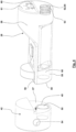
- Fig. 2 shows a piston-cylinder unit 1 in the area of the cylinder head 4.
- a sensor signal channel 26 opens into the pressure chamber 33 of the piston-cylinder unit 1.
- a collimator 35 is arranged in the sensor signal channel 26.
- the collimator 35 has a flat end face on the side facing the piston movement sensor 28, which is oriented transversely to the longitudinal central axis 30.
- the collimator 35 is designed to be rotationally symmetrical on the other side, wherein the collimator 35 can, for example, have a curved and in particular parabolic longitudinal section, as shown.
- the collimator 35 has an annular groove 36 in which a sealing element 37, here an O-ring 38, is arranged.
- the sealing element 37 ensures a hydraulic seal between the inner wall of the sensor signal channel 26 and the collimator 35.
- the sensor signal channel 26 has a circumferential shoulder 39. If the pressure chamber 33 is pressurized with hydraulic pressure, the pressure acts on the spherical end face facing the piston 7 Hydraulic pressure to a hydraulic force that presses the collimator 35 against the shoulder 39. This pressure of the collimator 35 on the shoulder 39 and/or the effect of the sealing element 37 can ensure that the transverse bore 27 is not exposed to hydraulic fluid and therefore no additional sealing measures need to be taken in the transverse bore 27. On the other hand, possible This seal means that dismantling of the piston movement sensor 28 is possible without hydraulic fluid being able to escape from the transverse bore 27.
- a securing element 40 in the form of a screw 41, a positioning and/or alignment element 42, the piston movement sensor 28, a sensor cable 43 and a housing plug 44 are mounted in the transverse bore, the housing plug 44 being attached to a housing 46 of the housing via fastening screws 45 Cylinder head 4 is attached.
- the positioning and/or alignment element 42 is cylindrical with a diameter such that the positioning and/or alignment element 42 can be inserted precisely into the transverse bore 27.
- the underside of the positioning and/or alignment element 42 is flat for the illustrated embodiment.
- the underside of the positioning and/or alignment element 42 rests on a bottom 47 of the transverse bore 27, which is designed here as a blind hole.
- the positioning and/or alignment element 42 On the side facing the piston movement sensor 28, the positioning and/or alignment element 42 is basically flat, but is designed with a step 48. On this side, the positioning and/or alignment element 42 has a (here cylindrical) receptacle 49, in which a permanent magnet 50 is accommodated, which can be glued to the receptacle 49 or pressed into it. The outer surface of the permanent magnet 50 is arranged flush with a partial surface of the end face of the positioning and/or alignment element 42 away from the step 48.
- a (here cylindrical) receptacle 49 in which a permanent magnet 50 is accommodated, which can be glued to the receptacle 49 or pressed into it.
- the outer surface of the permanent magnet 50 is arranged flush with a partial surface of the end face of the positioning and/or alignment element 42 away from the step 48.
- the positioning and/or alignment element 42 On the side facing away from the piston movement sensor 28, the positioning and/or alignment element 42 has an internal thread 51 arranged eccentrically to the longitudinal axis 53 of the transverse bore 27. In the aligned position of the positioning and/or alignment element 42 installed in the transverse bore 27, this is aligned Internal thread 51 of the positioning and/or alignment element 42 with an eccentric bore 52 opening into the transverse bore 27, through which the screw 41 extends from the outside through the housing 46. In this way, the positioning and/or alignment element 42 is fixed in the correct position and orientation.
- the positioning and/or alignment element 42 also has a transverse bore 54, possibly with an internal thread. It's not like in Fig. 2 shown a hole 52 is present or used, which is oriented parallel to the longitudinal axis 53 of the transverse hole 27, but rather a hole is provided in the housing 46, which is vertical to the plane of the drawing Fig. 2 is oriented, as an alternative to the attachment via the screw 41, the positioning and/or alignment element 42 can be attached via a screw which is vertical to the plane of the drawing Fig. 2 extends through the housing 46 and is screwed in the inner end region to the transverse bore 54 of the positioning and / or alignment element 42.
- the piston movement sensor 28 has a sensor housing 55, the external geometry of which is cylindrical with a diameter such that the sensor housing 55 can find a precise fit in the transverse bore 27.
- the sensor housing 25 has recesses in which the electronic component and the transmitting and/or receiving unit for the high-frequency signal are arranged.
- the sensor housing 55 On the side facing the positioning and/or alignment element 42, the sensor housing 55 has a step 56 which is designed corresponding to the step 48 of the positioning and/or alignment element 42. Away from the steps 48, 56, the positioning and/or alignment element 42 and the sensor housing 55 form contact surfaces 57, 58 which are oriented transversely to the longitudinal axis 53, in the area in which these components rest against one another in the direction of the longitudinal axis 53, which predetermines the axial position of the piston movement sensor 28 is.
- the steps 48, 56 form a positive fit against rotation about the longitudinal axis 53, which predetermines the orientation of the piston movement sensor 28.
- a corresponding receptacle 59 with a permanent magnet 60 is provided on the sensor housing 55, aligned with the receptacle 49 and the permanent magnet 50 of the positioning and/or alignment element 42.
- the permanent magnet 60 is also fixed in the receptacle 59, for example by gluing or pressing it in. The magnetic force between the permanent magnets 50, 60 secures the system and thus the position and alignment between the positioning and/or alignment element 42 and the piston movement sensor 28.
- the sensor housing 55 On the side facing away from the positioning and/or alignment element 42, the sensor housing 55 has a flat end face 61.
- the piston movement sensor 28 has an internal thread 62, which is formed here by a thread insert 63 injected into the sensor housing 55.
- the internal thread 62 forms a dismantling driver 64.
- a plug receptacle 65 is provided in the end face 61, into which a plug 66 of the sensor cable 43 can be inserted.
- the format of the plug 66 and the plug receptacle 65 is a 5-pin pico-clasp connection (registered trademark).
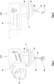
- FIG 5 and 6 show a housing plug 44-I, where "I" here indicates that it is a housing plug of a first type (see the explanations for the first type above).
- the housing plug 44-I is L-shaped with a leg 67 and a leg 68 which is angled here at an angle of 90 °.
- a plug receptacle is provided in the end face of the leg 68, into which a plug 69 of the sensor cable 43 can be plugged in.
- both the plug receptacle and the plug 69 have the “pico-clasp” format.
- the outer end region of the leg 68 When oriented coaxially to the longitudinal axis 53, the outer end region of the leg 68 extends into the transverse bore 27.
- the end region of the leg 68 can have a circumferential bead 70 or a sealing element.
- the bead 70 creates a frictional, elastically prestressed securing of the leg 68 in the transverse bore 27.
- a seal can be provided here.
- the leg 68 has a circumferential flange 71.
- the flange 71 is accommodated in a corresponding receptacle or recess in the housing 46.
- the flange 71 has through holes oriented parallel to the longitudinal axis 53, via which the flange 71 can be screwed to corresponding threaded holes in the housing 46.
- several holes are provided in the flange 71 and threaded holes in the housing 46, so that the housing plug 44-I can be screwed to the housing 46 in different orientations about the longitudinal axis 53.
- the end region of the leg 67 forms the connecting plug 34, which enables the connecting cable to be connected.
- the connecting plug 34 has, as shown in particular in Fig. 5 can be seen via 5 pins 72.
- the housing plug 44-I of the first type can be designed according to the subtypes explained at the beginning.
- housing plug 44-II shows a housing plug 44-II, where "II" here indicates that it is a housing plug of a second type.
- the housing plug 44-II of the second type can be designed according to the subtypes explained at the beginning.
- the electronic components are integrated into the housing plug 44 in order to modify the transmitted signals from the plug 69 to the connecting plug 34.
- the piston movement sensor 28 is used to directly measure the stroke of the piston 7 or the piston rod 8 within the piston-cylinder unit 1.
- the piston movement sensor 28 is preferably based on a non-contact measuring radar system in which the transit time between a transmitting unit and the end face of the piston 7 or the piston rod 8 and the reflected signal is evaluated back to a receiving unit. The position and/or speed can then be determined from the transit time with high accuracy and robustness.
- the piston-cylinder unit 1 with the integrated piston movement sensor 28 is preferably designed in accordance with protection class IP69K.
- the piston movement sensor 28 can be used to determine a stroke that is in the range of 10 mm to 2,000 mm, for example 30 mm to 1,800 mm or 40 mm to 1,600 mm.
- a resolution in the range of 0.2 mm to 4 mm, for example 0.5 to 2 mm or 0.8 to 1.5 mm, can be achieved.
- Another advantage of sealing the sensor signal channel 26 by a sealing element or a multifunctional collimator 35 is that the high hydraulic pressures, which also 100 bar to 600 bar cannot lead to deformation, stress and damage to the piston movement sensor 28, the sensor housing 55 and the electronic components of the piston movement sensor 28.
- the pico-clasp connector used for the sensor cable 43 and its connection to the piston movement sensor 28 and the housing plug 44 can have five pins, which can be assigned GND, VDC, CAN LO, CAN HI and an analog signal.
- the analog signal can be used to transmit a pulse width modulated signal (PWM), with the measurement signal being transmitted via pulse width modulation.
- PWM pulse width modulated signal
- a voltage or a current that is proportional to the measurement signal is transmitted as an analog signal.
- the piston movement sensor 28 may not only measure the stroke and/or the speed of the piston 7 or the piston rod 8. It is possible that, alternatively, other measured variables (such as the temperature) can also be measured, transmitted and/or evaluated. The temperature can be used for temperature compensation.
- a PWM signal is transmitted, it preferably has a frequency of 500 Hz.
- the duty cycle provides information about the measured path of the piston. For example, if the piston is fully retracted, the duty cycle can be 5%, while for the fully extended state of the piston, the duty cycle can be 95%.
Abstract
Die Erfindung betrifft eine Kolben-Zylinder-Einheit (1). Ein Kolbenbewegungssensor (28) ist in einer Querbohrung (27) eines Zylinderkopfs (4) der Kolben-Zylinder-Einheit (1) angeordnet. Erfindungsgemäß ist in der Querbohrung (27) an einem Boden (47) ein Positionier- und/oder Ausrichtelement (42) abgestützt, an dem wiederum der Kolbenbewegungssensor (28) abgestützt ist. Das Positionier- und/oder Ausrichtelement (42) gibt die axiale Position des Kolbenbewegungssensors (28) in der Querbohrung (27) vor. Zusätzlich kann Positionier- und/oder Ausrichtelement (42) die Ausrichtung des Kolbenbewegungssensors (28) vorgeben.Die erfindungsgemäße Kolben-Zylinder-Einheit (1) findet bspw. Einsatz für eine Arbeitsmaschine, Baumaschine, landwirtschaftliche Maschine, eine maritime Maschine, einen Radlader, einen Bagger, einen Kipper, einen Kran, einen Stapler oder eine Hebebühne.The invention relates to a piston-cylinder unit (1). A piston movement sensor (28) is arranged in a transverse bore (27) of a cylinder head (4) of the piston-cylinder unit (1). According to the invention, a positioning and/or alignment element (42) is supported in the transverse bore (27) on a base (47), on which the piston movement sensor (28) is in turn supported. The positioning and/or alignment element (42) specifies the axial position of the piston movement sensor (28) in the transverse bore (27). In addition, the positioning and/or alignment element (42) can specify the orientation of the piston movement sensor (28). The piston-cylinder unit (1) according to the invention is used, for example, for a work machine, construction machine, agricultural machine, a maritime machine, a wheel loader, an excavator, a tipper, a crane, a forklift or a lifting platform.
Description
Die vorliegende Erfindung betrifft eine Kolben-Zylinder-Einheit. Die Kolben-Zylinder-Einheit kann in einer Arbeitsmaschine (insbesondere eine Baumaschine, eine landwirtschaftliche Maschine, eine maritime Maschine, ein Radlader, ein Bagger, ein Kipper, ein Kran, ein Stapler, eine Hebebühne oder eine andere Arbeitsmaschine, die in bekannter Weise Einsatz findet im Maschinenbau) eingesetzt werden. Die Kolben-Zylinder-Einheit kann dabei bspw. einem Lenken, Stützen, Ausschieben, Neigen, Heben, Senken oder sonstigen Bewegen eines Teils der Arbeitsmaschine (insbesondere eines Werkzeugs, einer Schwinge oder eines anderen Teils der Arbeitsmaschine) dienen. Vorzugsweise handelt es sich um eine hydraulische Kolben-Zylinder-Einheit.The present invention relates to a piston-cylinder unit. The piston-cylinder unit can be used in a known manner in a work machine (in particular a construction machine, an agricultural machine, a maritime machine, a wheel loader, an excavator, a tipper, a crane, a forklift, a lifting platform or another work machine found in mechanical engineering). The piston-cylinder unit can be used, for example, to steer, support, push out, tilt, lift, lower or otherwise move a part of the work machine (in particular a tool, a rocker arm or another part of the work machine). It is preferably a hydraulic piston-cylinder unit.
Des Weiteren betrifft die Erfindung ein Set mit einer Kolben-Zylinder-Einheit, wobei auch dieses Set Einsatz finden kann für eine Arbeitsmaschine.Furthermore, the invention relates to a set with a piston-cylinder unit, whereby this set can also be used for a work machine.
Schließlich betrifft die Erfindung eine Gruppe von Kolben-Zylinder-Einheiten, wobei die Gruppe unterschiedliche Teilgruppen aufweist und die Kolben-Zylinder-Einheiten der unterschiedlichen Teilgruppen für unterschiedliche Einsatzzwecke gestaltet und bestimmt sind. Eine derartige Gruppe von Kolben-Zylinder-Einheiten kann beispielsweise für die unterschiedlichen Einsatzzwecke von einem Hersteller hergestellt, angeboten und vertrieben oder von einem Vertriebsunternehmen angeboten und vertrieben werden oder von einem Kunden für die unterschiedlichen Einsatzzwecke bevorratet und/oder benutzt werden.Finally, the invention relates to a group of piston-cylinder units, the group having different subgroups and the piston-cylinder units of the different subgroups being designed and intended for different purposes. Such a group of piston-cylinder units can, for example, be manufactured, offered and sold by a manufacturer for different purposes, or offered and sold by a sales company, or stored and/or used by a customer for different purposes.
Eine gattungsgemäße Kolben-Zylinder-Einheit ist aus der Druckschrift
An den Teil der Druckkammer 33, der durch das Zylinderrohr 31 begrenzt ist, schließt sich eine Teilkammer 25 der Druckkammer 33 in dem Zylinderkopf 4 an. Die Teilkammer 25 ist mit dem Anschluss 24 verbunden. In diese Teilkammer 25 mündet ein sich axial erstreckender Sensorsignalkanal 26. Der Sensorsignalkanal 26 ist ebenfalls Teil der Druckkammer 33 und somit mit dem Hydraulikfluid gefüllt. Der Sensorsignalkanal 26 ist wiederum mit einer sich radial zu der Längsmittelachse 30 in dem Zylinderkopf 4 erstreckenden Querbohrung 27 verbunden. Die Querbohrung 27 erstreckt sich bis zur äußeren Oberfläche des Zylinderkopfs 4 und kann mittels einer nicht dargestellten Ausgleichsbohrung mit der Umgebung verbunden sein. In der Querbohrung 27 ist ein Kolbenbewegungssensor 28 angeordnet. Der Kolbenbewegungssensor 28 dient dazu, mittels Hochfrequenztechnik die axiale Position des Kolbens 7 in dem Zylinder 2 zu erfassen. Zu diesem Zweck sendet der Kolbenbewegungssensor 28 ein Hochfrequenzsignal aus, welches durch den Sensorsignalkanal 26 und durch die Teilkammer 25 sowie durch die Drucckammer 33 auf die Stirnfläche des Kolbens 7 oder der Kolbenstange 8 auftrifft und nach der Reflektion durch diese Stirnseite wieder zurück zu dem Kolbenbewegungssensor 28 gelangt. Aus dem reflektierten Signal kann dann mittels der Hochfrequenztechnik, insbesondere durch Auswertung der Laufzeit, das Bewegungssignal, insbesondere der zurückgelegte Weg der Stirnseite, ermittelt werden. Für das in
Eine Weiterentwicklung dieser Kolben-Zylinder-Einheit 1 ist aus der Druckschrift
Der vorliegenden Erfindung liegt die Aufgabe zugrunde, eine Kolben-Zylinder-Einheit mit einem in dem Zylinderkopf integrierten Kolbenbewegungssensor vorzuschlagen, die insbesondere hinsichtlich
- des Herstellungsaufwands und/oder
- der Bauteilvielfalt und/oder
- der Positionierung und Ausrichtung des Kolbenbewegungssensors relativ zu dem Zylinderkopf und/oder
- des Montage- und/oder Demontageaufwands und/oder
- der Variabilität der Einsatzbedingungen und der Anschlussbedingungen an die Arbeitsmaschine
- the manufacturing effort and/or
- the variety of components and/or
- the positioning and orientation of the piston movement sensor relative to the cylinder head and/or
- the assembly and/or disassembly effort and/or
- the variability of the operating conditions and the connection conditions to the working machine
Des Weiteren liegt der Erfindung die Aufgabe zugrunde, ein Set mit einer Kolben-Zylinder-Einheit vorzuschlagen, welches für den Einsatz der Kolben-Zylinder-Einheit für unterschiedliche Einsatzzwecke nutzbar ist.Furthermore, the invention is based on the object of proposing a set with a piston-cylinder unit, which can be used for the use of the piston-cylinder unit for different purposes.
Schließlich liegt der Erfindung die Aufgabe zugrunde, eine Gruppe von Kolben-Zylinder-Einheiten vorzuschlagen, in der zwei Teilgruppen für unterschiedliche Einsatzzwecke gestaltet und bestimmt sind, aber dennoch eine geringe Bauteilvielfalt vorhanden ist.Finally, the invention is based on the object of proposing a group of piston-cylinder units in which two subgroups are designed and intended for different purposes, but there is still a small variety of components.
Die Aufgabe der Erfindung wird erfindungsgemäß mit den Merkmalen der unabhängigen Patentansprüche gelöst. Weitere bevorzugte erfindungsgemäße Ausgestaltungen sind den abhängigen Patentansprüchen zu entnehmen.The object of the invention is achieved according to the invention with the features of the independent patent claims. Further preferred embodiments according to the invention can be found in the dependent patent claims.
Die Erfindung schlägt eine Kolben-Zylinder-Einheit vor, die einen Zylinder mit einem Zylinderkopf, einen in dem Zylinder axial bewegbaren Kolben und einen Kolbenbewegungssensor aufweist. Hierbei ist der Kolbenbewegungssensor in einer eine Längsachse aufweisenden Querbohrung des Zylinderkopfs angeordnet. Insoweit kann die Kolben-Zylinder-Einheit auch gemäß dem eingangs angeführten Stand der Technik in den unterschiedlichen Varianten ausgebildet sein.The invention proposes a piston-cylinder unit which has a cylinder with a cylinder head, a piston which can be moved axially in the cylinder and a piston movement sensor. Here, the piston movement sensor is arranged in a transverse bore of the cylinder head that has a longitudinal axis. In this respect, the piston-cylinder unit can also be designed in the different variants according to the prior art mentioned at the beginning.
Die erfindungsgemäße Ausgestaltung basiert insbesondere auf der Erkenntnis, dass für die erforderliche Genauigkeit der Messergebnisse des in der Querbohrung angeordneten Kolbenbewegungssensors entscheidend ist, dass sich der Kolbenbewegungssensor und damit die Sende-und/oder Empfangseinheit für die hochfrequente Strahlung (oder ein anderes Sensorsignal)
- sowohl in der vorbestimmten Position in der Querbohrung, die die axiale Position des Kolbenbewegungssensors entlang der Längsachse der Querbohrung beschreibt,
- als auch in der vorbestimmten Ausrichtung. die die Drehstellung des Kolbenbewegungssensors um die Längsachse der Querbohrung und damit die Richtung der Aussendung des Signals des Kolbenbewegungssensors beschreibt,
- both in the predetermined position in the transverse bore, which describes the axial position of the piston movement sensor along the longitudinal axis of the transverse bore,
- as well as in the predetermined orientation. which describes the rotational position of the piston movement sensor about the longitudinal axis of the transverse bore and thus the direction of transmission of the signal from the piston movement sensor,
Möglich ist auch, dass für den Fall, dass gemäß dem Stand der Technik in einer Baureihe von Kolben-Zylinder-Einheiten mit unterschiedlichen Abmessungen (insbesondere unterschiedlichen Durchmessern des Zylinderrohrs und damit Dimensionen des Zylinderkopfs) Kolbenbewegungssensoren und insbesondere Sensorgehäuse mit unterschiedlichen Dimensionen hergestellt werden müssen. Grund hierfür ist, dass die unterschiedlichen Dimensionen der Kolben-Zylinder-Einheiten unterschiedliche Abstände des Sensorsignalkanals im Inneren des Zylinderkopfs von dem Anschlussstecker an der Außenfläche des Zylinderkopfs zur Folge haben, was unterschiedliche Längen des Sensorgehäuses bedingt.It is also possible that in the event that, according to the prior art, piston movement sensors and in particular sensor housings with different dimensions have to be produced in a series of piston-cylinder units with different dimensions (in particular different diameters of the cylinder tube and thus dimensions of the cylinder head). The reason for this is that the different dimensions of the piston-cylinder units result in different distances between the sensor signal channel inside the cylinder head and the connector on the outer surface of the cylinder head, which requires different lengths of the sensor housing.
In diesem Spannungsfeld schlägt die Erfindung die folgende Verbesserung vor: Erfindungsgemäß findet ein Positionier- und/oder Ausrichtelement Einsatz. Das Positionier- und/oder Ausrichtelement gewährleistet die richtige Positionierung des Kolbenbewegungssensors in Richtung der Längsachse der Querbohrung, so dass mittels der Positionierung Sorge dafür getragen wird, dass das Hochfrequenzsignal des Kolbenbewegungssensors an der richtigen Stelle durch den Sensorsignalkanal, einen etwaigen Kollimator und die Druckkammer hindurchtritt und/oder an der richtigen Stelle auf die Stirnseite des Kolbens oder der Kolbenstange auftrifft. Mittels des Positionier- und/oder Ausrichtelements kann alternativ oder kumulativ auch die Ausrichtung des Kolbenbewegungssensors vorgegeben werden. Findet das Positionier- und/oder Ausrichtelement kumulativ zum Positionieren und Ausrichten des Kolbenbewegungssensors Einsatz, kann auf einfache und zuverlässige Weise gewährleistet werden, dass eine Abweichung der Position und Ausrichtung eines gesendeten Hochfrequenzsignals des Kolbenbewegungssensors innerhalb eines vorbestimmten kleinen Toleranzbereichs liegt.In this area of tension, the invention proposes the following improvement: According to the invention, a positioning and/or alignment element is used. The positioning and/or alignment element ensures the correct positioning of the piston movement sensor in the direction of the longitudinal axis of the transverse bore, so that the positioning ensures that the high-frequency signal of the piston movement sensor is at the correct position Point passes through the sensor signal channel, any collimator and the pressure chamber and / or hits the end face of the piston or piston rod at the right place. The positioning and/or alignment element can alternatively or cumulatively also be used to specify the orientation of the piston movement sensor. If the positioning and/or alignment element is used cumulatively for positioning and aligning the piston movement sensor, it can be ensured in a simple and reliable manner that a deviation in the position and orientation of a transmitted high-frequency signal of the piston movement sensor lies within a predetermined small tolerance range.
Erfindungsgemäß ist das Positionier- und/oder Ausrichtelement in der Querbohrung angeordnet und hierbei in Richtung der Längsachse der Querbohrung, nämlich in die Montagerichtung, in der Querbohrung abgestützt. Diese Abstützung kann beispielsweise an einer Querfläche, Schrägfläche, einer Stufe, Verjüngung oder einem Ringbund der Querbohrung erfolgen. Damit nimmt das Positionier- und/oder Ausrichtelement eine definierte axiale Position in der Querbohrung ein, die bereits bei der Herstellung der Querbohrung, nämlich bei der Herstellung der Querfläche, Schrägfläche, Stufe, Verjüngung oder des Ringbunds, vorgegeben werden kann.According to the invention, the positioning and/or alignment element is arranged in the transverse bore and is supported in the transverse bore in the direction of the longitudinal axis of the transverse bore, namely in the assembly direction. This support can take place, for example, on a transverse surface, inclined surface, a step, taper or an annular collar of the transverse bore. The positioning and/or alignment element thus assumes a defined axial position in the transverse bore, which can already be specified during the production of the transverse bore, namely during the production of the transverse surface, inclined surface, step, taper or the annular collar.
An dem Positionier- und/oder Ausrichtelement ist dann der Kolbenbewegungssensor in Richtung der Längsachse an dem Positionier- und/oder Ausrichtelement abgestützt. Da das Positionier-und/oder Ausrichtelement in der Querbohrung eine definierte axiale Position einnimmt, kann über die Abstützung des Kolbenbewegungssensors an dem Positionier- und/oder Ausrichtelement gewährleistet werden, dass auch der Kolbenbewegungssensor eine definierte Position in der Querbohrung einnimmt.The piston movement sensor is then supported on the positioning and/or alignment element in the direction of the longitudinal axis on the positioning and/or alignment element. Since the positioning and/or alignment element occupies a defined axial position in the transverse bore, the support of the piston movement sensor on the positioning and/or alignment element can ensure that the piston movement sensor also occupies a defined position in the transverse bore.
Vorteilhaft ist, dass für den Fall, dass derselbe Kolbenbewegungssensor verwendet wird für Kolben-Zylinder-Einheiten unterschiedlicher Dimensionen, derselben Kolbenbewegungssensor in den unterschiedlichen Kolben-Zylinder-Einheiten Einsatz finden kann, wobei dann aber eine Anpassung der vorbestimmten Position des Kolbenbewegungssensors in der Querbohrung dadurch erfolgen kann, dass das Positionier- und/oder Ausrichtelement unterschiedliche Längen aufweist.It is advantageous that in the event that the same piston movement sensor is used for piston-cylinder units of different dimensions, the same piston movement sensor can be used in the different piston-cylinder units, but this then requires an adjustment of the predetermined position of the piston movement sensor in the transverse bore can be done that the positioning and / or alignment element has different lengths.
Wie zuvor erwähnt, kann die Abstützung des Positionier- und/oder Ausrichtelements durch eine beliebige Querfläche, Schrägfläche, Stufe, Verjüngung oder einen Ringbund u. ä. der Querbohrung gewährleistet werden. Für einen besonders einfachen Vorschlag der Erfindung kann die Querbohrung als Sacklochbohrung ausgebildet sein, wobei dann das Positionier- und/oder Ausrichtelement an einem Boden (insbesondere dem Randbereich eines kegelförmigen Bodens) der Sacklochbohrung abgestützt sein. In diesem Fall kann durch die Tiefe der Sacklochbohrung die Position des Positionier- und/oder Ausrichtelements und damit auch des Kolbenbewegungssensors vorgegeben werden.As mentioned above, the support of the positioning and/or alignment element can be ensured by any transverse surface, inclined surface, step, taper or an annular collar, etc. of the transverse bore. For a particularly simple proposal of the invention, the Transverse bore can be designed as a blind hole, in which case the positioning and / or alignment element can be supported on a bottom (in particular the edge region of a conical bottom) of the blind hole. In this case, the position of the positioning and/or alignment element and thus also of the piston movement sensor can be specified by the depth of the blind hole.
Möglich ist, dass eine Ausrichtung des Positionier- und/oder Ausrichtelements um die Längsachse der Querbohrung vorgegeben ist. Dies kann beispielsweise durch einen Formschluss der Querschnitte des Gehäuses des Positionier- und/oder Ausrichtelements und der Querbohrung erfolgen. So kann beispielsweise die Querbohrung eine in Richtung der Längsachse verlaufende Nut oder Ausnehmung (oder eine Rippe oder einen Vorsprung) aufweisen, die oder der formschlüssig zusammenwirkt mit einer Rippe oder einem Vorsprung (oder einer Nut oder Ausnehmung) des Gehäuses des Positionier- und/oder Ausrichtelements. Möglich ist aber auch, dass die Ausrichtung des Positionier- und/oder Ausrichtelements dadurch gewährleistet wird, dass eine dem Boden der Querbohrung zugewandte Stirnseite des Gehäuses des Positionier-und/oder Ausrichtelements eine exzentrische Ausnehmung (oder einen Vorsprung) aufweist, der eingreift in einen entsprechenden Vorsprung (oder eine Ausnehmung) des Bodens.It is possible that an alignment of the positioning and/or alignment element around the longitudinal axis of the transverse bore is predetermined. This can be done, for example, by a positive connection between the cross sections of the housing of the positioning and/or alignment element and the transverse bore. For example, the transverse bore can have a groove or recess (or a rib or a projection) running in the direction of the longitudinal axis, which cooperates in a form-fitting manner with a rib or a projection (or a groove or recess) of the housing of the positioning and/or Alignment element. However, it is also possible for the alignment of the positioning and/or alignment element to be ensured in that an end face of the housing of the positioning and/or alignment element facing the bottom of the transverse bore has an eccentric recess (or a projection) which engages in one corresponding projection (or a recess) of the floor.
Ein weiterer Aspekt der Erfindung widmet sich der Sicherung des Positionier- und/oder Ausrichtelements innerhalb der Querbohrung. Vorgeschlagen wird, dass mindestens ein Sicherungselement vorhanden ist. Das Sicherungselement dient zur Sicherung der Längsposition des Positionier- und/oder Ausrichtelements in der Querbohrung. Somit dient das Sicherungselement der Gewährleistung, dass sowohl das Positionier- und/oder Ausrichtelement als auch der Kolbenbewegungssensor an ihrer vorbestimmten Position sind und auch in Betrieb bleiben. Alternativ oder kumulativ möglich ist, dass mittels des mindestens einen Sicherungselements eine Sicherung der Ausrichtung des Positionier- und/oder Ausrichtelements um die Längsachse der Querbohrung (und damit u. U. auch eine Sicherung der Ausrichtung des Kolbenbewegungssensors) erfolgt.A further aspect of the invention is dedicated to securing the positioning and/or alignment element within the transverse bore. It is suggested that at least one security element be present. The securing element serves to secure the longitudinal position of the positioning and/or alignment element in the transverse bore. The securing element thus serves to ensure that both the positioning and/or alignment element and the piston movement sensor are in their predetermined position and remain in operation. Alternatively or cumulatively, it is possible for the at least one securing element to be used to secure the alignment of the positioning and/or alignment element about the longitudinal axis of the transverse bore (and thus possibly also to secure the alignment of the piston movement sensor).
Für die Art der Ausgestaltung des Sicherungselements gibt es vielfältige Möglichkeiten. So kann beispielsweise ein Sicherungsbolzen, ein Sicherungssplint, eine Rastverbindung, eine Nut-Federverbindung zur Sicherung einer Ausrichtung, usw. Einsatz finden. Für eine sehr einfache Ausführungsform ist das Sicherungselement eine Schraube. Die Schraube kann sich dabei parallel zur Längsachse der Querbohrung erstrecken. Möglich ist beispielsweise, dass sich die Schraube durch eine Bohrung von der anderen Seite durch den Boden der Sacklochbohrung erstreckt. Möglich ist aber auch, dass sich eine Schraube, die das Sicherungselement bildet, radial zu einer Längsachse der Querbohrung erstreckt. In jedem Fall ist die Schraube von außen an dem Zylinderkopf zugänglich und erstreckt sich durch eine Bohrung bis zu dem Positionier-und/oder Ausrichtelement, wo dann die Schraube mit einem Innengewinde des Positionier-und/oder Ausrichtelements verschraubt ist. Möglich ist des Weiteren, dass das Positionier-und/oder Ausrichtelement sowohl eine stirnseitige Gewindebohrung aufweist, die genutzt wird, wenn sich die Schraube parallel zur Längsachse der Querbohrung erstreckt, als auch eine radial orientierte Gewindebohrung aufweist für eine Montage in dem Fall, dass sich die Schraube radial zur Längsachse der Querbohrung erstreckt.There are a variety of options for the type of design of the security element. For example, a safety bolt, a safety pin, a snap connection, a tongue and groove connection to secure alignment, etc. can be used. For a very simple embodiment, the securing element is a screw. The screw can extend parallel to the longitudinal axis of the transverse bore. It is possible, for example, that the Screw through a hole from the other side extending through the bottom of the blind hole. However, it is also possible for a screw, which forms the securing element, to extend radially to a longitudinal axis of the transverse bore. In any case, the screw is accessible from the outside of the cylinder head and extends through a hole to the positioning and/or alignment element, where the screw is then screwed to an internal thread of the positioning and/or alignment element. It is also possible for the positioning and/or alignment element to have both an end-side threaded hole, which is used when the screw extends parallel to the longitudinal axis of the transverse hole, and a radially oriented threaded hole for assembly in the event that the screw extends radially to the longitudinal axis of the transverse bore.
Das Positionier- und/oder Ausrichtelement und der Kolbenbewegungssensor liegen vorzugsweise über Kontaktflächen unmittelbar aneinander an. Diese Kontaktflächen können die richtige Positionierung des Kolbenbewegungssensors in Richtung der Längsachse der Querbohrung gewährleisten.The positioning and/or alignment element and the piston movement sensor preferably lie directly against one another via contact surfaces. These contact surfaces can ensure the correct positioning of the piston movement sensor in the direction of the longitudinal axis of the transverse bore.
Möglich ist, dass nicht nur die axiale Position des Kolbenbewegungssensors in der Querbohrung vorgegeben werden muss. Vielmehr kann auch erforderlich sein, dass eine Ausrichtung des Kolbenbewegungssensors hinsichtlich seines Drehwinkels um die Längsachse der Querbohrung vorgegeben werden muss. Die Vorgabe des Drehwinkels kann bspw. erforderlich sein, damit ein von dem Kolbenbewegungssensor ausgesendetes Sensorsignal durch einen Sensorsignalkanal hindurchtreten und/oder an einer definierten Stelle und/oder unter einer definierten Ausrichtung auf eine Stirnfläche des Kolbens oder der Kolbenstange auftreffen kann. Diese Ausrichtung kann beispielsweise dadurch vorgegeben werden, dass der Kolbenbewegungssensor formschlüssig in Umfangsrichtung mit der Querbohrung zusammenwirkt, sodass einerseits über den Formschluss die Ausrichtung vorgegeben ist und andererseits hierdurch eine derart vorgegebene Ausrichtung auch im Betrieb aufrecht erhalten wird. Beispielsweise kann die Querbohrung eine in Richtung der Längsachse verlaufende Nut oder eine Ausnehmung aufweisen, in welche(r) dann ein Vorsprung oder eine Rippe des Gehäuses des Kolbenbewegungssensors angeordnet ist. Umgekehrt möglich ist, dass die Querbohrung eine in Richtung der Längsachse verlaufende Rippe oder einen Vorsprung aufweist, der eingreift in eine Nut oder Ausnehmung des Gehäuses des Kolbenbewegungssensors. Möglich ist auch, dass die Querbohrung einerseits und das Gehäuse des Kolbenbewegungssensors andererseits korrespondierende nicht runde, bspw. elliptische Querschnitte aufweisen, die ein passgenaues Einsetzen in der zutreffenden Ausrichtung gewährleisten.It is possible that not only the axial position of the piston movement sensor in the transverse bore must be specified. Rather, it may also be necessary for an orientation of the piston movement sensor to be specified with regard to its angle of rotation about the longitudinal axis of the transverse bore. The specification of the angle of rotation may be necessary, for example, so that a sensor signal emitted by the piston movement sensor can pass through a sensor signal channel and/or strike an end face of the piston or piston rod at a defined location and/or under a defined orientation. This alignment can be specified, for example, in that the piston movement sensor interacts positively in the circumferential direction with the transverse bore, so that on the one hand the alignment is specified via the positive connection and on the other hand, such a specified alignment is also maintained during operation. For example, the transverse bore can have a groove or a recess running in the direction of the longitudinal axis, in which a projection or a rib of the housing of the piston movement sensor is then arranged. Conversely, it is possible for the transverse bore to have a rib or a projection running in the direction of the longitudinal axis, which engages in a groove or recess in the housing of the piston movement sensor. It is also possible that the transverse bore on the one hand and the housing of the piston movement sensor on the other hand are corresponding non-round ones, for example. have elliptical cross-sections that ensure precise insertion in the correct orientation.
Für einen Vorschlag der Erfindung sind die Kontaktflächen des Positionier- und/oder Ausrichtelements einerseits und des Kolbenbewegungssensors andererseits über einen Formschluss in Umfangsrichtung um die Längsachse der Querbohrung miteinander verbunden. Dieser Formschluss schränkt dann die möglichen relativen Ausrichtungen des Kolbenbewegungssensors einerseits und des Positionier- und/oder Ausrichtelements (im Folgenden Kontaktelemente) andererseits ein oder gibt diese sogar vor. Für diesen Formschluss gibt es vielfältige Möglichkeiten. Um lediglich einige, die Erfindung nicht beschränkende Beispiele zu nennen, kann eines der beiden Kontaktelemente einen Vorsprung aufweisen, der in eine Vertiefung des anderen Kontaktelements eingreift. Möglich ist auch, dass eine Stirnfläche eines Kontaktelements eine Stufe aufweist, die formschlüssig in Wechselwirkung tritt mit einer entsprechenden Stufe des anderen Kontaktelements zur Gewährleistung der Verdrehsicherung und Vorgabe der Ausrichtung.For one proposal of the invention, the contact surfaces of the positioning and/or alignment element on the one hand and of the piston movement sensor on the other hand are connected to one another via a positive connection in the circumferential direction around the longitudinal axis of the transverse bore. This positive connection then limits or even specifies the possible relative orientations of the piston movement sensor on the one hand and of the positioning and/or alignment element (hereinafter referred to as contact elements) on the other hand. There are a variety of options for this form fit. To give just a few examples that do not limit the invention, one of the two contact elements can have a projection that engages in a recess in the other contact element. It is also possible for an end face of a contact element to have a step that interacts in a form-fitting manner with a corresponding step of the other contact element to ensure anti-twist protection and specification of the alignment.
Ein weiterer Aspekt der Erfindung widmet sich der Ermöglichung einer Demontage des Kolbenbewegungssensors, die beispielsweise erfolgen kann zu Wartungszwecken, im Fall eines Defektes des Kolbenbewegungssensors, zu Reinigungszwecken oder zum Einsatz eines anderen Kolbenbewegungssensors mit einem anderen Messbereich oder einer anderen Messgenauigkeit. In diesem Fall ist vorteilhaft, wenn der Kolbenbewegungssensor lösbar an dem Positionier- und/oder Ausrichtelement gehalten ist, aber dennoch die Verbindung eine gewisse Haltekraft gewährleistet. Vorteilhaft ist dabei, wenn für die Demontage lediglich eine Demontagekraft aufgebracht werden muss, die einen Schwellwert der Haltekraft der Verbindung überschreitet.A further aspect of the invention is dedicated to enabling dismantling of the piston movement sensor, which can be done, for example, for maintenance purposes, in the event of a defect in the piston movement sensor, for cleaning purposes or to use another piston movement sensor with a different measuring range or a different measuring accuracy. In this case, it is advantageous if the piston movement sensor is detachably held on the positioning and/or alignment element, but the connection still ensures a certain holding force. It is advantageous if only a dismantling force that exceeds a threshold value of the holding force of the connection has to be applied for dismantling.
Für eine Ausgestaltung der Erfindung erfolgt eine Verbindung des Kolbenbewegungssensors mit dem Positionier- und/oder Ausrichtelement über eine Rastverbindung. In diesem Fall gibt die Rastkraft der Rastverbindung den Schwellwert für die Haltekraft vor - bringt der Monteur eine Demontagekraft auf den Kolbenbewegungssensor auf, die größer ist als die Rastkraft, kann die Rastverbindung gelöst werden und der Kolbenbewegungssensor von dem Positionier- und/oder Ausrichtelement demontiert werden und aus der Querbohrung entnommen werden.For one embodiment of the invention, the piston movement sensor is connected to the positioning and/or alignment element via a latching connection. In this case, the latching force of the latching connection specifies the threshold value for the holding force - if the fitter applies a dismantling force to the piston movement sensor that is greater than the latching force, the latching connection can be released and the piston movement sensor can be dismantled from the positioning and / or alignment element and removed from the cross hole.
Für eine andere Ausführungsform findet ein Permanentmagnet Einsatz, der eine magnetische Haltekraft zwischen dem Kolbenbewegungssensor und dem Positionier- und/oder Ausrichtelement erzeugt. Für die Demontage ist in diesem Fall der Schwellwert für die Haltekraft vorgegeben durch die Magnetkraft. Im Rahmen der Erfindung ist auch möglich, dass jeweils der Kolbenbewegungssensor und das Positionier- und/oder Ausrichtelement einen Permanentmagneten aufweisen, zwischen denen dann die Magnetkraft erzeugt wird.For another embodiment, a permanent magnet is used which generates a magnetic holding force between the piston movement sensor and the positioning and/or alignment element. In this case, the threshold value for the holding force for dismantling is determined by the magnetic force. Within the scope of the invention, it is also possible for the piston movement sensor and the positioning and/or alignment element to each have a permanent magnet, between which the magnetic force is then generated.
Für die Demontage kann der Monteur die erforderliche Demontagekraft auf beliebige Weise aufbringen. Für einen Vorschlag der Erfindung weist der Kolbenbewegungssensor im Bereich einer Stirnseite auf der Seite, die dem Positionier- und/oder Ausrichtelement abgewandt ist, einen Demontage-Mitnehmer auf. Der Demontage-Mitnehmer ist mit einem Demontagewerkzeug koppelbar. Hierbei kann über das Demontagewerkzeug und den Demontage-Mitnehmer die erforderliche Demontagekraft auf den Kolbenbewegungssensor aufgebracht werden. Beispielsweise kann der Demontage-Mitnehmer als eine Art Hakenverbindung ausgebildet sein, in die ein gegenhakendes Demontagewerkzeug eingehakt wird, der Demontage-Mitnehmer und das Demontagewerkzeug können eine Rastverbindung ausbilden oder der Demontage-Mitnehmer und das Demontagewerkzeug sind über einen Permanentmagneten miteinander verbindbar sein. Für einen besonderen Vorschlag der Erfindung ist der Demontage-Mitnehmer ein Innengewinde des Kolbenbewegungssensors. In dieses Innengewinde kann dann ein Demontagestab eingeschraubt werden, so dass dann über den nach dem Einschrauben aus der Querbohrung herausragenden Demontagestab die erforderlichen Demontagekräfte auf den Kolbenbewegungssensor aufgebracht werden können.For disassembly, the installer can apply the required disassembly force in any way. For one proposal of the invention, the piston movement sensor has a dismantling driver in the area of an end face on the side that faces away from the positioning and/or alignment element. The dismantling driver can be coupled with a dismantling tool. The required dismantling force can be applied to the piston movement sensor using the dismantling tool and the dismantling driver. For example, the dismantling driver can be designed as a type of hook connection into which a counter-hooking dismantling tool is hooked, the dismantling driver and the dismantling tool can form a locking connection or the dismantling driver and the dismantling tool can be connected to one another via a permanent magnet. For a special proposal of the invention, the dismantling driver is an internal thread of the piston movement sensor. A dismantling rod can then be screwed into this internal thread, so that the required dismantling forces can then be applied to the piston movement sensor via the dismantling rod protruding from the cross hole after screwing in.
Hierbei kann das Innengewinde von einem Vollmaterial des Sensorgehäuses ausgebildet sein. Für einen Vorschlag der Erfindung ist das Innengewinde von einem Gewindeeinsatz ausgebildet. Dieser Gewindeeinsatz kann dann in ein Sensorgehäuse des Kolbenbewegungssensors eingespritzt sein oder in eine Bohrung des Sensorgehäuses eingepresst sein. Der Einsatz eines derartigen Gewindeeinsatzes ist beispielsweise dann von Vorteil, wenn das Sensorgehäuse aus einem Material hergestellt ist, bei dem die Herstellung eines Innengewindes nicht die erforderliche Festigkeit zur Verfügung stellt. In diesem Fall kann für das Material des Gewindeeinsatzes ein festeres Material, insbesondere Metall, gewählt werden. Das festere Material kann dann im Bereich des Gewindes die erforderliche Festigkeit für die Gewindeverbindung bereitstellen. Andererseits kann der Gewindeeinsatz eine vergrößerte Außenfläche aufweisen, die dann eine großflächige Anbindung und Kraftübertragung an das Sensorgehäuse ermöglicht.The internal thread can be formed from a solid material of the sensor housing. For one proposal of the invention, the internal thread is formed by a thread insert. This thread insert can then be injected into a sensor housing of the piston movement sensor or pressed into a hole in the sensor housing. The use of such a thread insert is advantageous, for example, if the sensor housing is made of a material in which the production of an internal thread does not provide the required strength. In this case, a stronger material, in particular metal, can be selected for the material of the thread insert. The stronger material can then provide the required strength for the threaded connection in the area of the thread. On the other hand, the threaded insert can have an enlarged outer surface, which then enables a large-area connection and power transmission to the sensor housing.
Grundsätzlich möglich ist, dass ein Anschlussstecker unmittelbar von dem Sensorgehäuse ausgebildet oder an diesem gehalten ist und nach außen aus der Querbohrung und dem Zylinderkopf herausragt, wo dann der Anschlussstecker mit den erforderlichen Anschlusskabeln verbunden werden kann. Für einen Vorschlag der Erfindung ist der Kolbenbewegungssensor über ein Sensorkabel mit einem Gehäusestecker verbunden. Somit verfügt die Sensoreinheit über zwei Teileinheiten, nämlich den Kolbenbewegungssensor und den Gehäusestecker, die über das Sensorkabel flexibel miteinander verbunden sind. Die Verbindung über das Sensorkabel ermöglicht auf einfache Weise eine Anpassung für die Verwendung desselben Kolbenbewegungssensors und desselben Gehäusesteckers für Kolben-Zylinder-Einheiten mit unterschiedlichen Dimensionen, indem für die unterschiedlichen Einbausituationen dann das Sensorkabel mehr oder weniger gekrümmt oder gestreckt eingebaut werden kann. Andererseits kann unter Umständen das Sensorgehäuse weniger massiv oder kürzer ausgebildet sein, da das Sensorgehäuse nicht den gesamten radialen Bereich von dem eigentlichen Messbereich bis hin zu dem Anschlussstecker überbrücken muss, sondern ein Teilbereich von dem Sensorkabel überbrückt werden kann.In principle, it is possible for a connection plug to be formed directly by or held on the sensor housing and to protrude outwards from the transverse bore and the cylinder head, where the connection plug can then be connected to the required connection cables. For one proposal of the invention, the piston movement sensor is connected to a housing plug via a sensor cable. The sensor unit therefore has two sub-units, namely the piston movement sensor and the housing plug, which are flexibly connected to one another via the sensor cable. The connection via the sensor cable enables a simple adjustment for the use of the same piston movement sensor and the same housing plug for piston-cylinder units with different dimensions, in that the sensor cable can then be installed more or less curved or stretched for the different installation situations. On the other hand, under certain circumstances, the sensor housing can be designed to be less massive or shorter, since the sensor housing does not have to bridge the entire radial area from the actual measuring area to the connecting plug, but rather a partial area can be bridged by the sensor cable.
Besonders vorteilhaft ist, wenn das Sensorkabel lösbar mit dem Kolbenbewegungssensor und/oder dem Gehäusestecker verbunden ist. Dies ermöglicht beispielsweise eine separate Montage zunächst nur des Kolbenbewegungssensors, dann den Anschluss des Sensorkabels und schließlich die Montage des Gehäusesteckers, wobei auch eine entsprechende separate Demontage erfolgen kann. Des Weiteren ist möglich, dass, beispielsweise zu Wartungszwecken oder im Fall eines Defektes lediglich ein Kolbenbewegungssensor oder ein Gehäusestecker ausgewechselt werden muss, während dann das verbleibende Teil von dem Kolbenbewegungssensor und dem Gehäusestecker weiter verwendet werden kann.It is particularly advantageous if the sensor cable is detachably connected to the piston movement sensor and/or the housing plug. This enables, for example, a separate assembly of initially only the piston movement sensor, then the connection of the sensor cable and finally the assembly of the housing plug, whereby a corresponding separate disassembly can also take place. Furthermore, it is possible that, for example for maintenance purposes or in the event of a defect, only a piston movement sensor or a housing plug needs to be replaced, while the remaining part of the piston movement sensor and the housing plug can then continue to be used.
Für einen besonderen Vorschlag der Erfindung wird aber durch die lösbare Verbindung mit dem Sensorkabel auch ermöglicht, dass derselbe Kolbenbewegungssensor mit unterschiedlichen Gehäusesteckern verwendet werden kann, um eine Anpassung an unterschiedliche Einsatzzwecke zu ermöglichen, die unterschiedliche Gehäusestecker bedingen.For a special proposal of the invention, however, the detachable connection to the sensor cable also makes it possible for the same piston movement sensor to be used with different housing plugs in order to enable adaptation to different applications that require different housing plugs.
Vorteilhaft ist auch, wenn der Gehäusestecker lösbar mit dem Zylinderkopf verbunden ist. Für einen Vorschlag der Erfindung verfügt zu diesem Zweck der Gehäusestecker über einen Flansch. Der Flansch kann dann mit dem Zylinderkopf verschraubt werden, was eine zuverlässige Verbindung zwischen Gehäusestecker und Zylinderkopf ermöglicht.It is also advantageous if the housing plug is detachably connected to the cylinder head. In one proposal of the invention, the housing plug has a flange for this purpose. The flange can then be screwed to the cylinder head, enabling a reliable connection between the housing plug and the cylinder head.
Möglich ist dabei sogar, dass der Flansch in unterschiedlichen Ausrichtungen des Gehäusesteckers um die Längsachse der Querbohrung mit dem Zylinderkopf verschraubt werden kann, womit den jeweiligen Einbaubedingungen Rechnung getragen werden kann.It is even possible for the flange to be screwed to the cylinder head in different orientations of the housing plug around the longitudinal axis of the transverse bore, which allows the respective installation conditions to be taken into account.
Möglich ist, dass im Rahmen der Erfindung beliebige unterschiedliche Gehäusestecker Einsatz finden. So können einerseits die Gehäusestecker eine unterschiedliche Form aufweisen. Möglich ist, dass ein erster Gehäusestecker geradlinig ausgebildet ist, während ein zweiter, im Rahmen der Erfindung einsetzbarer Gehäusestecker L-förmig ausgebildet ist. In diesem Fall kann der Gehäusestecker zwei abgewinkelte Schenkel aufweisen. Ein Schenkel erstreckt sich dann in das Innere der Querbohrung des Zylinderkopfs. Im Bereich einer Stirnseite dieses Schenkels kann dann ein Anschluss des Sensorkabels erfolgen. Hingegen erstreckt sich der andere Schenkel außenliegend von dem Zylinderkopf. Dabei ist möglich, dass sich dieser Schenkel radial zu der Längsachse der Querbohrung erstreckt. Für eine Einbausituation ist der Schenkel parallel zur Längsmittelachse des Zylinders der Kolben-Zylinder-Einheit orientiert, was für einige Einsatzzwecke vorteilhaft ist. In diesem Fall kann die Stirnseite des letztgenannten Schenkels zum Anschluss eines Anschlusskabels dienen.It is possible that any number of different housing plugs can be used within the scope of the invention. On the one hand, the housing plugs can have a different shape. It is possible that a first housing plug is designed to be straight, while a second housing plug that can be used within the scope of the invention is designed to be L-shaped. In this case, the housing plug can have two angled legs. One leg then extends into the interior of the transverse bore of the cylinder head. The sensor cable can then be connected in the area of one end face of this leg. On the other hand, the other leg extends on the outside of the cylinder head. It is possible for this leg to extend radially to the longitudinal axis of the transverse bore. For an installation situation, the leg is oriented parallel to the longitudinal central axis of the cylinder of the piston-cylinder unit, which is advantageous for some applications. In this case, the end face of the latter leg can be used to connect a connection cable.
Neben der Nutzung von Gehäusesteckern unterschiedlicher Formen in der erfindungsgemäßen Kolben-Zylinder-Einheit können die Gehäusestecker alternativ oder kumulativ auch mit unterschiedlichen Anschlussgeometrien und Belegungen der Pins ausgestattet sein.
- a) Möglich ist hierbei beispielsweise, dass ein erster Typ eines Gehäusesteckers als sogenannter DIN-Stecker ausgebildet ist. Beispielsweise kann es sich um einen DIN-Stecker M12 handeln, der 5-polig ausgebildet sein kann. Derartige DIN-Stecker sind in den Normen DIN 41524 (3- und 5-polig), DIN 45322 (5-
polig mit 60° Abstand), DIN 45326 (8-polig) und DIN 45329 (7-polig) (diese Normen ersetzt durch EN 60130-9) beschrieben.
Für diesen ersten Typ des Gehäusesteckers können dann wiederum unterschiedliche Untertypen verwendet werden, die sich durch die Belegung der Anschlusspins unterscheiden:- aa) Für einen ersten Untertyp ist ein erster Pin nicht belegt. Ein zweiter Pin ist mit der Funktion VDC (Spannungsversorgung des Kolbenbewegungssensors) belegt. Ein dritter Pin ist mit der Funktion GND (Erde) belegt. Ein vierter Pin ist mit dem Datenbus CAN HI belegt, während ein fünfter Pin mit einem Datenbus CAN LO belegt ist.
- ab) Für einen zweiten Untertyp des ersten Typs kann ein erster Pin nicht belegt sein, ein zweiter Pin mit VDC belegt sein, ein dritter Pin mit GND belegt sein, ein vierter Pin mit einem pulsweitenmodulierten Signal belegt sein und ein fünfter Pin nicht belegt sein.
- b) Für einen zweiten Typ des Gehäusesteckers ist der Gehäusestecker als sogenannter Deutsch-Stecker ausgebildet, wobei es sich beispielsweise um einen Deutsch-Stecker DT 04 handeln kann mit vier Pins.
Auch für den zweiten Typ sind unterschiedliche Untertypen möglich:- ba) So kann beispielsweise ein erster Untertyp des zweiten Typs mit einem ersten Pin ausgestattet sein, der die Funktion VDC gewährleistet. Der zweite Pin ist mit der Funktion CAN LO belegt, ein dritter Pin mit der Funktion GND sowie ein vierter Pin mit der Funktion CAN HI.
- bb) Hingegen kann für einen zweiten Untertyp des zweiten Typs ein erster Pin mit der Funktion VDC belegt sein, ein zweiter Pin mit der Funktion GND belegt sein, ein dritter Pin mit der Funktion PWM belegt sein und ein vierter Pin nicht belegt sein.
- a) It is possible, for example, for a first type of housing plug to be designed as a so-called DIN plug. For example, it can be an M12 DIN plug, which can be 5-pin. Such DIN plugs are in the standards DIN 41524 (3- and 5-pin), DIN 45322 (5-pin with 60° spacing), DIN 45326 (8-pin) and DIN 45329 (7-pin) (these standards replace described by EN 60130-9).
For this first type of housing connector, different subtypes can then be used, which differ in the assignment of the connection pins:- aa) For a first subtype, a first pin is not assigned. A second pin is assigned the VDC function (voltage supply for the piston movement sensor). A third pin is assigned the GND (earth) function. A fourth pin is with the CAN HI data bus is occupied, while a fifth pin is occupied by a CAN LO data bus.
- ab) For a second subtype of the first type, a first pin can be unoccupied, a second pin can be assigned VDC, a third pin can be assigned GND, a fourth pin can be assigned a pulse width modulated signal and a fifth pin can be unoccupied.
- b) For a second type of housing plug, the housing plug is designed as a so-called Deutsch plug, which can be, for example, a Deutsch plug DT 04 with four pins.
Different subtypes are also possible for the second type:- ba) For example, a first subtype of the second type can be equipped with a first pin that ensures the VDC function. The second pin is assigned the CAN LO function, a third pin is assigned the GND function and a fourth pin is assigned the CAN HI function.
- bb) On the other hand, for a second subtype of the second type, a first pin can be assigned the VDC function, a second pin can be assigned the GND function, a third pin can be assigned the PWM function and a fourth pin can be unoccupied.
Erfindungsgemäß ist ermöglicht, dass ein- und derselbe Kolbenbewegungssensor über das lösbare Sensorkabel je nach Anforderungen und Einsatzzweck wahlweise mit Gehäusesteckern unterschiedlicher Geometrien und Abwinklungen der Schenkel des Gehäusesteckers und/oder Gehäusesteckern der unterschiedlichen genannten Typen und Untertypen kombiniert werden können.According to the invention, it is possible for one and the same piston movement sensor to be combined via the detachable sensor cable, depending on the requirements and intended use, with housing plugs of different geometries and angles of the legs of the housing plug and/or housing plugs of the different types and subtypes mentioned.
Für die aus dem Stand der Technik bekannten Ausführungsformen war der Kolbenbewegungssensor über den Sensorsignalkanal hydraulisch mit der Druckkammer verbunden, so dass der Kolbenbewegungssensor selber mit dem Hydraulikfluid beaufschlagt war. Dies hat erfordert, dass das Sensorgehäuse des Kolbenbewegungssensors mit Ringnuten auf beiden Seiten von dem Sensorsignalkanal ausgestattet war, um den Kolbenbewegungssensor in der Querbohrung abzudichten. Ist für diese Ausführungsformen ein Austausch des Kolbenbewegungssensors erforderlich, ist ein Ablassen des Hydraulikfluids erforderlich, da ansonsten das Hydraulikfluid für den demontierten Kolbenbewegungssensor aus der Querbohrung austreten würde. Die Erfindung schlägt für eine Ausgestaltung der Kolben-Zylinder-Einheit vor, dass die Querbohrung über ein Dichtelement hydraulisch von der Druckkammer getrennt ist. In diesem Fall kann eine Demontage des Kolbenbewegungssensors aus der Querbohrung erfolgen, ohne dass ein Übertritt des Hydraulikfluids zu der Querbohrung möglich ist, da der Übertritt über das Dichtelement abgesperrt ist. Hierbei ist das Dichtelement vorzugsweise so gestaltet und das Material desselben so gewählt, dass dieses die Hochfrequenzstrahlung des Kolbenbewegungssensors durchlässt und möglichst nicht auf unerwünschte Weise beeinträchtigt.For the embodiments known from the prior art, the piston movement sensor was hydraulically connected to the pressure chamber via the sensor signal channel, so that the piston movement sensor itself was acted upon by the hydraulic fluid. This required that the sensor housing of the piston motion sensor be equipped with annular grooves on both sides of the sensor signal channel to seal the piston motion sensor in the cross bore. If the piston movement sensor needs to be replaced for these embodiments, the hydraulic fluid must be drained, otherwise the hydraulic fluid for the dismantled piston movement sensor would escape from the transverse bore. For an embodiment of the piston-cylinder unit, the invention proposes that the transverse bore is hydraulically separated from the pressure chamber via a sealing element. In this case, the piston movement sensor can be dismantled from the transverse bore without the hydraulic fluid being able to pass over to the transverse bore, since the passage is blocked by the sealing element. Here, the sealing element is preferably designed and the material thereof selected so that it allows the high-frequency radiation from the piston movement sensor to pass through and, if possible, does not impair it in an undesirable way.
Für einen besonderen Vorschlag der Erfindung ist das Dichtelement als Kollimator ausgebildet, so dass in diesem Fall der Kollimator multifunktional ist, da dieser die gewünschte Strahlbündelung und parallele Ausrichtung gewährleistet und zusätzlich als Dichtelement wirkt. Möglich ist dabei, dass der Kollimator im Bereich seiner Außenfläche mindestens eine Ringnut aufweist, in die ein Dichtring, insbesondere ein O-Ring eingesetzt ist, welcher unter Abdichtung in Wechselwirkung tritt mit dem Sensorsignalkanal, in welchem der Kollimator angeordnet ist.For a particular proposal of the invention, the sealing element is designed as a collimator, so that in this case the collimator is multifunctional, since it ensures the desired beam bundling and parallel alignment and also acts as a sealing element. It is possible for the collimator to have at least one annular groove in the area of its outer surface, into which a sealing ring, in particular an O-ring, is inserted, which interacts with a seal with the sensor signal channel in which the collimator is arranged.
Eine weitere Lösung der der Erfindung zugrunde liegenden Aufgabe stellt ein Set dar, welches eine Kolben-Zylinder-Einheit aufweist, wie dies zuvor erläutert worden ist. In dem Set sind mindestens zwei Gehäusestecker vorhanden. Diese beiden Gehäusestecker sind für unterschiedliche Einsatzzwecke gestaltet und bestimmt. Somit kann es sich beispielsweise bei den beiden unterschiedlichen Gehäusesteckern um Gehäusestecker der zuvor erläuterten unterschiedlichen Geometrien, Typen und/oder Untertypen handeln. Die beiden Gehäusestecker können dann wahlweise in die Querbohrung eingesetzt werden und es kann die Befestigung des gewählten Gehäusesteckers an dem Gehäuse der Kolben-Zylinder-Einheit erfolgen. Hierbei ist der jeweils gewählte Gehäusestecker dann mittels des Sensorkabels mit dem Kolbenbewegungssensor verbunden. Auf diese Weise kann für den Kunden ein Set bereitgestellt werden, mit dem derselbe Kolbenbewegungssensor in unterschiedlichen Einbausituationen mit unterschiedlichen Gehäusesteckern verbunden werden kann, womit die Anwendungsvielfalt erweitert werden kann und die Bauteilvielfalt verringert werden kann.A further solution to the problem on which the invention is based is a set which has a piston-cylinder unit, as explained previously. The set contains at least two housing plugs. These two housing connectors are designed and intended for different purposes. Thus, for example, the two different housing plugs can be housing plugs of the previously explained different geometries, types and/or subtypes. The two housing plugs can then optionally be inserted into the transverse bore and the selected housing plug can be attached to the housing of the piston-cylinder unit. The selected housing plug is then connected to the piston movement sensor using the sensor cable. In this way, a set can be provided for the customer with which the same piston movement sensor can be connected to different housing connectors in different installation situations, which can expand the variety of applications and reduce the variety of components.
Eine weitere Lösung der der Erfindung zugrunde liegenden Aufgabe stellt eine Gruppe von Kolben-Zylinder-Einheiten dar, wie diese zuvor erläutert worden sind. Hierbei weist die Gruppe zwei unterschiedliche Teilgruppen von Kolben-Zylinder-Einheiten auf, wobei diese beiden Teilgruppen dann für unterschiedliche Einsatzzwecke gestaltet und bestimmt sind. In der ersten Teilgruppe weisen die Kolben-Zylinder-Einheiten erste Gehäusestecker auf, während in der zweiten Teilgruppe die Kolben-Zylinder-Einheiten die zweiten Gehäusestecker aufweisen. Die ersten Gehäusestecker und die zweiten Gehäusestecker sind für unterschiedliche Einsatzzwecke gestaltet und bestimmt, womit dann auch die Kolben-Zylinder-Einheiten der beiden Teilgruppen für unterschiedliche Einsatzzwecke gestaltet und bestimmt sind. Die ersten Gehäusestecker und zweiten Gehäusestecker können sich beispielsweise durch die zuvor erläuterten unterschiedlichen Geometrien, Typen und/oder Untertypen voneinander unterscheiden. In den Kolben-Zylinder-Einheiten der ersten Teilgruppe und den Kolben-Zylinder-Einheiten der zweiten Teilgruppe sind dann baugleiche Kolbenbewegungssensoren vorhanden. Beispielsweise kann eine derartige Gruppe mit den unterschiedlichen Teilgruppen von einem Hersteller oder einem Vertriebsunternehmen angeboten werden, so dass der Kunde dann je nach dem gewünschten Einsatzzweck die Kolben-Zylinder-Einheiten der ersten Teilgruppe oder der zweiten Teilgruppe erwerben kann. Möglich ist aber auch, dass bei einem Endkunden, in einer Reparaturwerkstatt oder einem Hersteller einer Arbeitsmaschine eine derartige Gruppe von Kolben-Zylinder-Einheiten für die unterschiedlichen Einsatzzwecke bereitgehalten wird.A further solution to the problem on which the invention is based is a group of piston-cylinder units, as explained above. The group points out two different subgroups of piston-cylinder units, with these two subgroups then being designed and intended for different purposes. In the first subgroup, the piston-cylinder units have first housing plugs, while in the second subgroup the piston-cylinder units have the second housing plugs. The first housing plugs and the second housing plugs are designed and intended for different purposes, which means that the piston-cylinder units of the two subgroups are also designed and intended for different purposes. The first housing plugs and second housing plugs can differ from one another, for example, by the different geometries, types and/or subtypes explained above. Identical piston movement sensors are then present in the piston-cylinder units of the first subgroup and the piston-cylinder units of the second subgroup. For example, such a group with the different subgroups can be offered by a manufacturer or a sales company, so that the customer can then purchase the piston-cylinder units of the first subgroup or the second subgroup depending on the desired application. However, it is also possible for an end customer, a repair shop or a manufacturer of a work machine to have such a group of piston-cylinder units available for different purposes.
Vorteilhafte Weiterbildungen der Erfindung ergeben sich aus den Patentansprüchen, der Beschreibung und den Zeichnungen.Advantageous developments of the invention result from the patent claims, the description and the drawings.
Die in der Beschreibung genannten Vorteile von Merkmalen und von Kombinationen mehrerer Merkmale sind lediglich beispielhaft und können alternativ oder kumulativ zur Wirkung kommen, ohne dass die Vorteile zwingend von erfindungsgemäßen Ausführungsformen erzielt werden müssen.The advantages of features and combinations of several features mentioned in the description are merely examples and can have an alternative or cumulative effect without the advantages necessarily having to be achieved by embodiments according to the invention.
Hinsichtlich des Offenbarungsgehalts - nicht des Schutzbereichs - der ursprünglichen Anmeldungsunterlagen und des Patents gilt Folgendes: Weitere Merkmale sind den Zeichnungen - insbesondere den dargestellten Geometrien und den relativen Abmessungen mehrerer Bauteile zueinander sowie deren relativer Anordnung und Wirkverbindung - zu entnehmen. Die Kombination von Merkmalen unterschiedlicher Ausführungsformen der Erfindung oder von Merkmalen unterschiedlicher Patentansprüche ist ebenfalls abweichend von den gewählten Rückbeziehungen der Patentansprüche möglich und wird hiermit angeregt. Dies betrifft auch solche Merkmale, die in separaten Zeichnungen dargestellt sind oder bei deren Beschreibung genannt werden. Diese Merkmale können auch mit Merkmalen unterschiedlicher Patentansprüche kombiniert werden. Ebenso können in den Patentansprüchen aufgeführte Merkmale für weitere Ausführungsformen der Erfindung entfallen, was aber nicht für die unabhängigen Patentansprüche des erteilten Patents gilt.With regard to the disclosure content - not the scope of protection - of the original application documents and the patent, the following applies: Further features can be found in the drawings - in particular the geometries shown and the relative dimensions of several components to one another as well as their relative arrangement and operative connection. The combination of features of different embodiments of the invention or of features of different patent claims is also possible, deviating from the selected relationships of the patent claims, and is hereby encouraged. This also applies to features that are shown in separate drawings or are mentioned in their description. These features can also be combined with features of different patent claims. Likewise, features listed in the patent claims may be omitted for further embodiments of the invention, but this does not apply to the independent patent claims of the granted patent.
Die in den Patentansprüchen und der Beschreibung genannten Merkmale sind bezüglich ihrer Anzahl so zu verstehen, dass genau diese Anzahl oder eine größere Anzahl als die genannte Anzahl vorhanden ist, ohne dass es einer expliziten Verwendung des Adverbs "mindestens" bedarf. Wenn also beispielsweise von einem Element die Rede ist, ist dies so zu verstehen, dass genau ein Element, zwei Elemente oder mehr Elemente vorhanden sind. Die in den Patentansprüchen angeführten Merkmale können durch weitere Merkmale ergänzt werden oder die einzigen Merkmale sein, die der Gegenstand des jeweiligen Patentanspruchs aufweist.The features mentioned in the patent claims and the description are to be understood in terms of their number in such a way that exactly this number or a larger number than the number mentioned is present, without the need for an explicit use of the adverb "at least". For example, when we talk about an element, this should be understood to mean that there is exactly one element, two elements or more elements. The features listed in the patent claims can be supplemented by further features or can be the only features that the subject of the respective patent claim has.
Die in den Patentansprüchen enthaltenen Bezugszeichen stellen keine Beschränkung des Umfangs der durch die Patentansprüche geschützten Gegenstände dar. Sie dienen lediglich dem Zweck, die Patentansprüche leichter verständlich zu machen.The reference symbols contained in the patent claims do not represent a limitation on the scope of the subject matter protected by the patent claims. They merely serve the purpose of making the patent claims easier to understand.
Im Folgenden wird die Erfindung anhand in den Figuren dargestellter bevorzugter Ausführungsbeispiele weiter erläutert und beschrieben.
- Fig. 1
- zeigt in einem Längsschnitt eine Kolben-Zylinder-Einheit gemäß dem Stand der Technik.
- Fig. 2
- zeigt in einem Teillängsschnitt eine Kolben-Zylinder-Einheit im Bereich des Zylinderkopfs.
- Fig. 3
- zeigt in einer räumlichen Explosionsansicht den Zylinderkopf gemäß
Fig. 2 mit zugeordneten Bauelementen. - Fig. 4
- zeigt in einer räumlichen Ansicht einen Kolbenbewegungssensor und ein Positio-nier- und/oder Ausrichtelement.
- Fig. 5
- zeigt in einer räumlichen Ansicht einen Gehäusestecker des Typs DIN-Stecker (5-polig) mit Sensorkabel.
- Fig. 6
- zeigt den Gehäusestecker mit Sensorkabel gemäß
Fig. 5 in einer Seitenansicht. - Fig. 7
- zeigt in einer räumlichen Ansicht einen Gehäusestecker des Typs Deutsch-Stecker (4-polig) mit Sensorkabel.
- Fig. 8
- zeigt den Gehäusestecker gemäß
Fig. 7 in einer Seitenansicht.
- Fig. 1
- shows a longitudinal section of a piston-cylinder unit according to the prior art.
- Fig. 2
- shows a partial longitudinal section of a piston-cylinder unit in the area of the cylinder head.
- Fig. 3
- shows the cylinder head in a spatial exploded view
Fig. 2 with assigned components. - Fig. 4
- shows a three-dimensional view of a piston movement sensor and a positioning and/or alignment element.
- Fig. 5
- shows a spatial view of a housing connector of the DIN plug type (5-pin) with sensor cable.
- Fig. 6
- shows the housing connector with sensor cable according to
Fig. 5 in a side view. - Fig. 7
- shows a three-dimensional view of a housing plug of the Deutsch plug type (4-pin) with sensor cable.
- Fig. 8
- shows the housing connector according to
Fig. 7 in a side view.
Sofern sich aus dem Folgenden nichts anderes ergibt, kann für die erfindungsgemäßen Ausführungsformen das eingangs zu dem Stand der Technik und zu der Ausführungsform gemäß
Wie aus der Explosionsdarstellung in
Gemäß
Auf der dem Kolbenbewegungssensor 28 zugewandten Seite ist das Positionier- und/oder Ausrichtelement 42 grundsätzlich eben, aber mit einer Stufe 48 ausgebildet. Auf dieser Seite verfügt das Positionier- und/oder Ausrichtelement 42 über eine (hier zylindrische) Aufnahme 49, in der ein Permanentmagnet 50 aufgenommen ist, der mit der Aufnahme 49 verklebt sein kann oder in diese eingepresst ist. Die Außenfläche des Permanentmagneten 50 ist dabei bündig zu einer Teilfläche der Stirnseite des Positionier- und/oder Ausrichtelement 42 abseits der Stufe 48 angeordnet.On the side facing the
Auf der dem Kolbenbewegungssensor 28 abgewandten Seite verfügt das Positionier- und/oder Ausrichtelement 42 über eine exzentrisch zu der Längsachse 53 der Querbohrung 27 angeordnetes Innengewinde 51. In der ausgerichteten, in die Querbohrung 27 eingebauten Stellung des Positionier- und/oder Ausrichtelements 42 fluchtet das Innengewinde 51 des Positionier-und/oder Ausrichtelements 42 mit einer in die Querbohrung 27 mündenden exzentrischen Bohrung 52, durch die sich die Schraube 41 von außen durch das Gehäuse 46 erstreckt. Auf diese Weise ist das Positionier- und/oder Ausrichtelement 42 in der richtigen Position und Ausrichtung fixiert.On the side facing away from the
Möglich ist, dass das Positionier- und/oder Ausrichtelement 42 auch eine Querbohrung 54, ggf. mit einem Innengewinde, aufweist. Ist nicht wie in
Der Kolbenbewegungssensor 28 verfügt über ein Sensorgehäuse 55, dessen Außengeometrie zylindrisch ist mit einem Durchmesser derart, dass das Sensorgehäuse 55 passgenaue Aufnahme in der Querbohrung 27 finden kann. Gegenüber diese Außengeometrie verfügt das Sensorgehäuse 25 über Rücksprünge, im Bereich welcher die Elektronikbaueinheit und die Sende- und/oder Empfangseinheit für das Hochfrequenzsignal angeordnet sind.The
Auf der dem Positionier- und/oder Ausrichtelement 42 zugewandten Seite verfügt das Sensorgehäuse 55 über eine Stufe 56, die entsprechend der Stufe 48 des Positionier- und/oder Ausrichtelements 42 ausgebildet ist. Abseits der Stufen 48, 56 bilden das Positionier- und/oder Ausrichtelement 42 und das Sensorgehäuse 55 quer zur Längsachse 53 orientierte Kontaktflächen 57, 58, im Bereich welcher diese Bauelemente in Richtung der Längsachse 53 aneinander anliegen, womit die axiale Position des Kolbenbewegungssensors 28 vorgegeben ist.On the side facing the positioning and/or
Hingegen bilden die Stufen 48, 56 einen Formschluss gegenüber einer Verdrehung um die Längsachse 53, womit die Ausrichtung des Kolbenbewegungssensors 28 vorgegeben ist. In der durch die Stufen 48, 56 vorgegebenen relativen Ausrichtung ist fluchtend zu der Aufnahme 49 und dem Permanentmagneten 50 des Positionier- und/oder Ausrichtelements 42 an dem Sensorgehäuse 55 eine entsprechende Aufnahme 59 mit einem Permanentmagneten 60 vorgesehen. Auch der Permanentmagnet 60 ist in der Aufnahme 59 fixiert, beispielsweise durch Einkleben oder Einpressen. Die Magnetkraft zwischen den Permanentmagneten 50, 60 sichert die Anlage und damit die Position und Ausrichtung zwischen dem Positionier- und/oder Ausrichtelement 42 und dem Kolbenbewegungssensor 28.On the other hand, the
Auf der dem Positionier- und/oder Ausrichtelement 42 abgewandten Seite verfügt das Sensorgehäuse 55 über eine ebene Stirnfläche 61. Im Bereich dieser Stirnfläche 61 verfügt der Kolbenbewegungssensor 28 über ein Innengewinde 62, welches hier von einem in das Sensorgehäuse 55 eingespritzten Gewindeeinsatz 63 ausgebildet ist. Das Innengewinde 62 bildet einen Demontage-Mitnehmer 64.On the side facing away from the positioning and/or
Des Weiteren ist in der Stirnseite 61 eine Steckeraufnahme 65 vorgesehen, in die ein Stecker 66 des Sensorkabels 43 eingesteckt werden kann. Vorzugsweise handelt es sich bei dem Format des Steckers 66 und der Steckeraufnahme 65 um eine 5-polige Pico-Clasp-Verbindung (eingetragene Marke).Furthermore, a
Wie in
Der außenliegende Endbereich des Schenkels 68 erstreckt sich bei Orientierung koaxial zur Längsachse 53 in die Querbohrung 27. Der Endbereich des Schenkels 68 kann über einen umlaufenden Wulst 70 oder ein Dichtelement verfügen. In dem in die Querbohrung 27 eingesetzten Zustand erzeugt der Wulst 70 eine reibschlüssige, elastisch vorgespannte Sicherung des Schenkels 68 in der Querbohrung 27. Ergänzend kann hier eine Abdichtung erfolgen.When oriented coaxially to the
Im Austrittsbereich des Schenkels 68 aus dem Gehäuse 46 des Zylinderkopfs 4 verfügt der Schenkel 68 über einen hier umlaufenden Flansch 71. Der Flansch 71 findet Aufnahme in einer korrespondierenden Aufnahme oder Vertiefung des Gehäuses 46. Der Flansch 71 verfügt über parallel zur Längsachse 53 orientierte Durchgangsbohrungen, über die der Flansch 71 mit korrespondierenden Gewindebohrungen des Gehäuses 46 verschraubt werden kann. Vorzugsweise sind mehrere Bohrungen in dem Flansch 71 sowie Gewindebohrungen in dem Gehäuse 46 vorgesehen, so dass ein Verschrauben des Gehäusesteckers 44-I in unterschiedlichen Ausrichtungen um die Längsachse 53 mit dem Gehäuse 46 möglich ist.In the exit area of the
Der Endbereich des Schenkels 67 bildet den Anschlussstecker 34, der den Anschluss des Anschlusskabels ermöglicht.The end region of the
Für den Gehäusestecker 44-I verfügt der Anschlussstecker 34, wie insbesondere in
In den Gehäusestecker 44 sind jeweils die elektronischen Bauelemente integriert, um eine Modifikation der übertragenen Signale von dem Stecker 69 zu dem Anschlussstecker 34 vorzunehmen.The electronic components are integrated into the
Mittels des Kolbenbewegungssensors 28 erfolgt eine direkte Messung des Hubs des Kolbens 7 oder der Kolbenstange 8 innerhalb der Kolben-Zylinder-Einheit 1. Der Kolbenbewegungssensor 28 basiert vorzugsweise auf einem berührungslos messenden Radarsystem, bei dem die Laufzeit zwischen einer Sendeeinheit, der Stirnfläche des Kolbens 7 oder der Kolbenstange 8 und des reflektierten Signals zurück zu einer Empfangseinheit ausgewertet wird. Aus der Laufzeit kann dann die Position und/oder die Geschwindigkeit mit hoher Genauigkeit und Robustheit ermittelt werden.The
Vorzugsweise ist die Kolben-Zylinder-Einheit 1 mit dem integrierten Kolbenbewegungssensor 28 entsprechend der Schutzart IP69K ausgebildet.The piston-
Möglich ist, dass mittels des Kolbenbewegungssensors 28 ein Hub ermittelt werden kann, der im Bereich von 10 mm bis 2.000 mm, beispielsweise 30 mm bis 1.800 mm oder 40 mm bis 1.600 mm liegt. Hierbei kann beispielsweise eine Auflösung im Bereich von 0,2mm bis 4 mm, beispielsweise 0,5 bis 2 mm oder 0,8 bis 1,5 mm erreicht werden.It is possible that the
Vorteilhaft ist des Weiteren an der Abdichtung des Sensorsignalkanals 26 durch ein Dichtelement oder einen multifunktionalen Kollimator 35, dass die hohen hydraulischen Drücke, die auch 100 Bar bis 600 Bar betragen können, nicht zu Deformationen, Beanspruchungen und Beschädigungen des Kolbenbewegungssensors 28, des Sensorgehäuses 55 und der elektronischen Bauelemente des Kolbenbewegungssensors 28 führen können.Another advantage of sealing the
Der für das Sensorkabel 43 und dessen Verbindung mit dem Kolbenbewegungssensor 28 und dem Gehäusestecker 44 eingesetzte Pico-Clasp-Stecker kann über fünf Pins verfügen, welche mit GND, VDC, CAN LO, CAN HI und einem analogen Signal belegt sein können.The pico-clasp connector used for the
Das analoge Signal kann der Übertragung eines pulsweitenmodulierten Signals (PWM) dienen, wobei über die Pulsweitenmodulation das Messsignal übertragen wird. Alternativ möglich ist, dass als analoges Signal eine Spannung oder ein Strom übertragen wird, der proportional zu dem Messsignal ist.The analog signal can be used to transmit a pulse width modulated signal (PWM), with the measurement signal being transmitted via pulse width modulation. Alternatively, it is possible that a voltage or a current that is proportional to the measurement signal is transmitted as an analog signal.
Der Kolbenbewegungssensor 28 misst unter Umständen nicht lediglich den Hub und/oder die Geschwindigkeit des Kolbens 7 bzw. der Kolbenstange 8. Möglich ist, dass alternativ auch weitere Messgrößen (wie bspw. die Temperatur) gemessen, übertragen und/oder oder ausgewertet werden. Die Temperatur kann für die Temperaturkompensation verwendet werden.The
Auch möglich ist, dass über den Gehäusestecker 44 eine bidirektionale Übertragung möglich ist, womit auch eine Softwareaktualisierung des Kolbenbewegungssensors 28 erfolgen kann und Update-Funktionen ausgeführt werden können.It is also possible that a bidirectional transmission is possible via the
Wird ein PWM-Signal übertragen, hat dieses vorzugsweise eine Frequenz von 500 Hz. Das Tastverhältnis gibt dabei Aufschluss über den gemessenen Weg des Kolbens. Befindet sich der Kolben vollständig eingefahren, kann beispielsweise das Tastverhältnis 5 % betragen, während für den voll ausgefahrenen Zustand des Kolbens das Tastverhältnis 95 % betragen kann.If a PWM signal is transmitted, it preferably has a frequency of 500 Hz. The duty cycle provides information about the measured path of the piston. For example, if the piston is fully retracted, the duty cycle can be 5%, while for the fully extended state of the piston, the duty cycle can be 95%.
- 11
- Kolben-Zylinder-EinheitPiston-cylinder unit
- 22
- Zylindercylinder
- 33
- Innenrauminner space
- 44
- Zylinderkopfcylinder head
- 55
- LagerbuchseBearing bushing
- 66
- AnschlussConnection
- 77
- KolbenPistons
- 88th
- KolbenstangePiston rod
- 99
- KolbenstangenaugePiston rod eye
- 1010
- LagerbuchseBearing bushing
- 1111
- FührungsbuchseGuide bushing
- 1212
- StangendichtungRod seal
- 1313
- O-RingO-ring
- 1414
- StützringSupport ring
- 1515
- O-RingO-ring
- 1616
- Abstreiferscraper
- 1717
- Gleitlagerbearings
- 1818
- Sicherungsmutterlock nut
- 1919
- O-RingO-ring
- 2020
- KolbenführungsringPiston guide ring
- 2121
- KolbendichtungPiston seal
- 2222
- KolbenführungsringPiston guide ring
- 2323
- SchweißnahtWeld
- 2424
- AnschlussConnection
- 2525
- TeilkammerPartial chamber
- 2626
- SensorsignalkanalSensor signal channel
- 2727
- QuerbohrungCross hole
- 2828
- KolbenbewegungssensorPiston movement sensor
- 2929
- HydraulikfluidHydraulic fluid
- 3030
- Längsmittelachse des ZylindersLongitudinal center axis of the cylinder
- 3131
- Zylinderrohrcylinder tube
- 3232
- DruckkammerPressure chamber
- 3333
- DruckkammerPressure chamber
- 3434
- AnschlusssteckerConnection plug
- 3535
- KollimatorCollimator
- 3636
- RingnutRing groove
- 3737
- DichtelementSealing element
- 3838
- O-RingO-ring
- 3939
- AbsatzParagraph
- 4040
- SicherungselementSecurity element
- 4141
- Schraubescrew
- 4242
- Positionier- und/oder AusrichtelementPositioning and/or alignment element
- 4343
- SensorkabelSensor cable
- 4444
- GehäusesteckerHousing connector
- 4545
- BefestigungsschraubenFastening screws
- 4646
- GehäuseHousing
- 4747
- BodenFloor
- 4848
- StufeLevel
- 4949
- AufnahmeRecording
- 5050
- PermanentmagnetPermanent magnet
- 5151
- Innengewindeinner thread
- 5252
- Bohrungdrilling
- 5353
- LängsachseLongitudinal axis
- 5454
- QuerbohrungCross hole
- 5555
- SensorgehäuseSensor housing
- 5656
- StufeLevel
- 5757
- KontaktflächeContact surface
- 5858
- KontaktflächeContact surface
- 5959
- AufnahmeRecording
- 6060
- PermanentmagnetPermanent magnet
- 6161
- Stirnflächeface
- 6262
- Innengewindeinner thread
- 6363
- GewindeeinsatzThread insert
- 6464
- Demontage-MitnehmerDismantling driver
- 6565
- SteckeraufnahmePlug receptacle
- 6666
- Stecker SensorkabelSensor cable connector
- 6767
- Schenkelleg
- 6868
- Schenkelleg
- 6969
- Stecker SensorkabelSensor cable connector
- 7070
- Wulstbead
- 7171
- Flanschflange
- 7272
- PinPin code
Claims (15)
e) in der Querbohrung (27) in Richtung der Längsachse (53) der Querbohrung (27) ein Positionier- und/oder Ausrichtelement (42) abgestützt ist und der Kolbenbewegungssensor (28) in Richtung der Längsachse (53) an dem Positionier- und/oder Ausrichtelement (42) abgestützt ist.Piston-cylinder unit (1)
e) a positioning and/or alignment element (42) is supported in the transverse bore (27) in the direction of the longitudinal axis (53) of the transverse bore (27) and the piston movement sensor (28) in the direction of the longitudinal axis (53) on the positioning and / or alignment element (42) is supported.
Priority Applications (2)
| Application Number | Priority Date | Filing Date | Title |
|---|---|---|---|
| EP22162782.1A EP4246000A1 (en) | 2022-03-17 | 2022-03-17 | Piston cylinder unit, set comprising a piston-cylinder unit and a group of piston-cylinder units |
| PCT/EP2023/056767 WO2023175082A1 (en) | 2022-03-17 | 2023-03-16 | Piston-cylinder unit, set comprising a piston-cylinder unit and a group of piston-cylinder units |
Applications Claiming Priority (1)
| Application Number | Priority Date | Filing Date | Title |
|---|---|---|---|
| EP22162782.1A EP4246000A1 (en) | 2022-03-17 | 2022-03-17 | Piston cylinder unit, set comprising a piston-cylinder unit and a group of piston-cylinder units |
Publications (1)
| Publication Number | Publication Date |
|---|---|
| EP4246000A1 true EP4246000A1 (en) | 2023-09-20 |
Family
ID=80786927
Family Applications (1)
| Application Number | Title | Priority Date | Filing Date |
|---|---|---|---|
| EP22162782.1A Pending EP4246000A1 (en) | 2022-03-17 | 2022-03-17 | Piston cylinder unit, set comprising a piston-cylinder unit and a group of piston-cylinder units |
Country Status (2)
| Country | Link |
|---|---|
| EP (1) | EP4246000A1 (en) |
| WO (1) | WO2023175082A1 (en) |
Citations (6)
| Publication number | Priority date | Publication date | Assignee | Title |
|---|---|---|---|---|
| JPH0399207U (en) * | 1990-01-30 | 1991-10-16 | ||
| US5182980A (en) * | 1992-02-05 | 1993-02-02 | Caterpillar Inc. | Hydraulic cylinder position sensor mounting apparatus |
| US6725761B1 (en) * | 2002-09-30 | 2004-04-27 | Prince Manufacturing Corporation | Spooling device assembly for hydraulic cylinder and method of assembling same |
| DE202019101788U1 (en) * | 2019-03-29 | 2019-04-10 | Mts Sensor Technologie Gmbh & Co. Kg | Hydraulic cylinder with integrated sensors |
| DE102019122121A1 (en) | 2019-08-16 | 2021-02-18 | Precision Nanosensors Inc | Piston-cylinder unit with radially installed piston position detection unit |
| EP3957868A1 (en) | 2020-08-20 | 2022-02-23 | Precision Nanosensors Inc | Piston cylinder unit with piston position sensing unit and collimator |
-
2022
- 2022-03-17 EP EP22162782.1A patent/EP4246000A1/en active Pending
-
2023
- 2023-03-16 WO PCT/EP2023/056767 patent/WO2023175082A1/en unknown
Patent Citations (6)
| Publication number | Priority date | Publication date | Assignee | Title |
|---|---|---|---|---|
| JPH0399207U (en) * | 1990-01-30 | 1991-10-16 | ||
| US5182980A (en) * | 1992-02-05 | 1993-02-02 | Caterpillar Inc. | Hydraulic cylinder position sensor mounting apparatus |
| US6725761B1 (en) * | 2002-09-30 | 2004-04-27 | Prince Manufacturing Corporation | Spooling device assembly for hydraulic cylinder and method of assembling same |
| DE202019101788U1 (en) * | 2019-03-29 | 2019-04-10 | Mts Sensor Technologie Gmbh & Co. Kg | Hydraulic cylinder with integrated sensors |
| DE102019122121A1 (en) | 2019-08-16 | 2021-02-18 | Precision Nanosensors Inc | Piston-cylinder unit with radially installed piston position detection unit |
| EP3957868A1 (en) | 2020-08-20 | 2022-02-23 | Precision Nanosensors Inc | Piston cylinder unit with piston position sensing unit and collimator |
Also Published As
| Publication number | Publication date |
|---|---|
| WO2023175082A1 (en) | 2023-09-21 |
Similar Documents
| Publication | Publication Date | Title |
|---|---|---|
| DE3525029C2 (en) | Piston-cylinder arrangement | |
| EP2814708B1 (en) | Main brake cylinder having a device for the contactless monitoring of the position and movement of a linearly movable piston | |
| DE102014101869A1 (en) | clutch unit | |
| EP3341251A1 (en) | Device for simulating a force on an actuation element of a vehicle, in particular a pedal force simulator | |
| EP3344967B1 (en) | Pressure sensor assembly and measurement converter for process instrumentation, comprising such a pressure sensor assembly | |
| DE102019122121A1 (en) | Piston-cylinder unit with radially installed piston position detection unit | |
| DE102005060674B4 (en) | Position sensor in rod construction and method for replacement | |
| DE19520682A1 (en) | Master cylinder | |
| AT519652B1 (en) | Sealing device and hydraulic piston with sealing device | |
| EP3957868A1 (en) | Piston cylinder unit with piston position sensing unit and collimator | |
| EP4246002B1 (en) | Piston-cylinder unit | |
| EP4246000A1 (en) | Piston cylinder unit, set comprising a piston-cylinder unit and a group of piston-cylinder units | |
| EP4246001A1 (en) | Piston cylinder unit, set comprising a piston-cylinder unit and a group of piston-cylinder units | |
| EP0985901A2 (en) | Measuring cable distance sensor with the drum fixed to the rotation angle sensor and ribbed half shells | |
| DE102013006321A1 (en) | Construction machine for soil compaction, in particular compactor, bandage casing segment and padfoot | |
| EP2123359B1 (en) | Pipette device for aspirating and dispensing a metered liquid | |
| DE602004012828T2 (en) | Holder for a transducer for cylinders | |
| DE10107814A1 (en) | Pressure sensor assembly for an automotive brake pressure regulation device used in a hydraulic anti-slip brake system, designed to mount in the pump housing without any modification to the housing | |
| WO2002009992A1 (en) | Brake master cylinder comprising plunger pistons and radial grooves inserted into the housing in order to receive sealing joints | |
| DE2502265C3 (en) | Pressure control device for a hydraulic dual-circuit vehicle brake system | |
| DE10120913A1 (en) | Master brake cylinder with plunger and radial grooves inserted in the housing to accommodate the sealing sleeves | |
| EP1634048A2 (en) | Pressure gauge array | |
| DE102019107671B3 (en) | Mechanical seal and method for assembling such a mechanical seal | |
| DE19929897C2 (en) | Closure structure for actuators | |
| DE102011086815A1 (en) | Housing for e.g. master cylinder of clutch or brake system of vehicle within hydraulic track, has additional securing component e.g. locking ring, arranged in region of plug connector for securing plug connector |
Legal Events
| Date | Code | Title | Description |
|---|---|---|---|
| PUAI | Public reference made under article 153(3) epc to a published international application that has entered the european phase |
Free format text: ORIGINAL CODE: 0009012 |
|
| STAA | Information on the status of an ep patent application or granted ep patent |
Free format text: STATUS: REQUEST FOR EXAMINATION WAS MADE |
|
| 17P | Request for examination filed |
Effective date: 20230103 |
|
| AK | Designated contracting states |
Kind code of ref document: A1 Designated state(s): AL AT BE BG CH CY CZ DE DK EE ES FI FR GB GR HR HU IE IS IT LI LT LU LV MC MK MT NL NO PL PT RO RS SE SI SK SM TR |
|
| GRAP | Despatch of communication of intention to grant a patent |
Free format text: ORIGINAL CODE: EPIDOSNIGR1 |
|
| STAA | Information on the status of an ep patent application or granted ep patent |
Free format text: STATUS: GRANT OF PATENT IS INTENDED |
|
| RIC1 | Information provided on ipc code assigned before grant |
Ipc: F15B 15/14 20060101ALN20240118BHEP Ipc: F15B 21/00 20060101ALI20240118BHEP Ipc: G01D 5/48 20060101ALI20240118BHEP Ipc: F15B 15/28 20060101AFI20240118BHEP |
|
| INTG | Intention to grant announced |
Effective date: 20240131 |
|
| GRAS | Grant fee paid |
Free format text: ORIGINAL CODE: EPIDOSNIGR3 |
|
| GRAA | (expected) grant |
Free format text: ORIGINAL CODE: 0009210 |
|
| STAA | Information on the status of an ep patent application or granted ep patent |
Free format text: STATUS: THE PATENT HAS BEEN GRANTED |