EP4245944B1 - Druckbeaufschlagungssystem für ein treppenhaus - Google Patents
Druckbeaufschlagungssystem für ein treppenhaus Download PDFInfo
- Publication number
- EP4245944B1 EP4245944B1 EP23161132.8A EP23161132A EP4245944B1 EP 4245944 B1 EP4245944 B1 EP 4245944B1 EP 23161132 A EP23161132 A EP 23161132A EP 4245944 B1 EP4245944 B1 EP 4245944B1
- Authority
- EP
- European Patent Office
- Prior art keywords
- stairwell
- control panel
- ventilating casing
- ventilating
- casing
- Prior art date
- Legal status (The legal status is an assumption and is not a legal conclusion. Google has not performed a legal analysis and makes no representation as to the accuracy of the status listed.)
- Active
Links
Images
Classifications
-
- E—FIXED CONSTRUCTIONS
- E04—BUILDING
- E04F—FINISHING WORK ON BUILDINGS, e.g. STAIRS, FLOORS
- E04F17/00—Vertical ducts; Channels, e.g. for drainage
- E04F17/04—Air-ducts or air channels
-
- E—FIXED CONSTRUCTIONS
- E04—BUILDING
- E04F—FINISHING WORK ON BUILDINGS, e.g. STAIRS, FLOORS
- E04F17/00—Vertical ducts; Channels, e.g. for drainage
- E04F17/02—Vertical ducts; Channels, e.g. for drainage for carrying away waste gases, e.g. flue gases; Building elements specially designed therefor, e.g. shaped bricks or sets thereof
-
- F—MECHANICAL ENGINEERING; LIGHTING; HEATING; WEAPONS; BLASTING
- F24—HEATING; RANGES; VENTILATING
- F24F—AIR-CONDITIONING; AIR-HUMIDIFICATION; VENTILATION; USE OF AIR CURRENTS FOR SCREENING
- F24F11/00—Control or safety arrangements
- F24F11/30—Control or safety arrangements for purposes related to the operation of the system, e.g. for safety or monitoring
- F24F11/32—Responding to malfunctions or emergencies
- F24F11/33—Responding to malfunctions or emergencies to fire, excessive heat or smoke
- F24F11/34—Responding to malfunctions or emergencies to fire, excessive heat or smoke by opening air passages
-
- F—MECHANICAL ENGINEERING; LIGHTING; HEATING; WEAPONS; BLASTING
- F24—HEATING; RANGES; VENTILATING
- F24F—AIR-CONDITIONING; AIR-HUMIDIFICATION; VENTILATION; USE OF AIR CURRENTS FOR SCREENING
- F24F7/00—Ventilation
- F24F7/04—Ventilation with ducting systems, e.g. by double walls; with natural circulation
- F24F7/06—Ventilation with ducting systems, e.g. by double walls; with natural circulation with forced air circulation, e.g. by fan positioning of a ventilator in or against a conduit
Definitions
- the present invention relates to an innovative system for pressurizing a predetermined environment in order to limit the spread of smoke in the event of a fire.
- the system object of the present invention is capable of preventing the smoke released during a fire from invading areas considered protected, such as for example stairwells.
- pressurization systems for stairwells are one of the most advantageous solutions for facilitating escape in the event of a fire. Indeed, in the event of a fire in a building, the smoke released by combustion represents a serious danger not only for people fleeing to a safe place but also for rescue teams. From this point of view, pressurization systems are extremely important for active protection in the event of fire: they favor the outflow of the occupants, they represent additional protection for rescuers against combustion products, even at high temperatures, they guarantee clear visibility and facilitate the identification of the fire source.
- pressurization systems have become a valid option for guaranteeing adequate safety conditions in multi-store buildings, being able to maintain sustainable conditions in protected spaces, such as escape routes, access routes for the fire brigade intervention teams, lobbies, stairways and other areas that need to be kept smoke-free.
- the UNI EN 12101-6: 2005 standard defines the specifications of these systems based on the type of control to be carried out and according to the fire safety objectives established in the general design of the building.
- the standard takes into consideration different classes of the pressurization system based on the structure, the intended use and the subdivision characteristics of the building, which are subordinate to the objective to be achieved (protection from exodus or the intervention of the fire brigade fire) and the type of exodus envisaged (protection in place, simultaneous or phased exodus).
- EP3542870A2 shows a pressurisation system for a stairwell according to the preamble of claim 1.
- the present invention has the objective of realizing an extremely efficient stairwell pressurization system capable of reducing the risks due to a fire as much as possible.
- This objective which is the main object of the present invention, is achieved by optimizing the regulating elements of the system, their calibration, precision and above all their reliability.
- the safety integrity levels are defined as a quantitative measure of risk reduction, the meaning of SIL can therefore be traced back to the measure that indicates the degree of reliability that a safety system must achieve in order to reduce the risk of an accident during its use.
- the safety integrity level is a number indicating the value of the probability that a system correctly performs an instrumental safety function within a pre-established period of time, i.e. it is the quantification of the reliability (or degree of reliability) achieved by any object that performs a safety-related function. The greater its reliability, the greater its ability to perform critical functions for the safety or for the availability of machines or systems.
- the SIL is assigned to each individual independent safety function (SIF), implemented by one or more Safety Instrumented Systems (SIS).
- SI Safety Instrumented Systems
- the pressurization system of a stairwell object of the present invention is configured to be extremely safe and reliable, by means of a suitable combination of equally reliable and redundant components, as specified in the attached independent system claim.
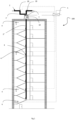
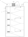
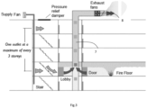
- FIGS 1 and 2 they schematically illustrate a pressurization system 100 of a stairwell to limit the spread of smoke, in the event of a fire, in this area, according to an embodiment of the present invention.
- the pressurization of the stairwell is achieved by introducing fresh air and thus providing a positive pressure differential which prevents smoke from entering the protected area.
- the system 100 comprises: a ventilating casing 1 for the introduction of air from the external environment, positioned above the building and in correspondence with the stairwell which must be pressurized, a duct 2 preferably made of sheet metal, connected to the ventilating casing 1, having an external portion 2' for the supply of air comprising at least one smoke sensor 20 and an internal portion 2" for the delivery of air passing through an internal wall of the stairwell and covering its entire height, at least one high precision pressure sensor 4.
- the pressure sensors 4 are three in number and are positioned on different floors of the stairwell.
- the three pressure sensors 4 are positioned on the second, sixth and top floor of the stairwell.
- these pressure sensors 4 are in a closer position and in any case on nonconsecutive planes of the stairwell.
- the internal portion 2" of the duct 2 has an adjustable outlet 3 on each floor.
- a programmable logic controller inserted in the control panel 5 positioned in a safe area, is electrically connected to the ventilating casing 1, to the pressure sensors 4, to at least one smoke sensor 20 of the system 100.
- a manual control panel 6 is positioned on the ground floor of the stairwell, so as to be usable by the emergency teams in manual mode (start/stop system with key selector and push-button panel for firefighters).
- the ventilating casing 1 comprises a plurality of fans 10 with electronically commutated (EC) motors.
- EC electronically commutated
- each fan 10 is equipped with an inverter on the motor, for the regulation of the flow rate/speed, this allows to avoid the insertion of the inverters necessary for the standard fans in the control panel 5 (reducing spaces and costs).
- the control panel 5 of the system manages the alarms, the start-up and/or regulation of the ventilating box 1, and includes:
- the flow rate of the ventilating casing 1 for introducing air into the stairwell is defined by a regulatory calculation and the air can be introduced alternatively either from the bottom or from the top of the stairwell.
- the ventilating casing 1 object of the present system comprises a plurality of fans 10 so that the air flow reaches the required flow rate and is characterized by a redundancy in the number of such fans 10, in order to be of the SIL2 type.
- the EN12101-6 and prEN12101-13 standards establish that such systems have an additional ventilating casing as a backup, precisely because there is a need for absolute certainty that the system can always operate in the event of a fire.
- the presence of an additional ventilating casing is not necessary since the plurality of fans 10 causes the ventilating casing 1 to assume a SIL2 reliability, demonstrated by the relative calculation.
- the ventilating casing 1 has, for example, a flow rate equal to 30,000 m3/h given by the presence of two fans 10 and a further additional fan 10 in redundancy.
- the further fan 10 automatically takes over which guarantees the redundancy function.
- adjustable vents 3 positioned on the various floors of the stairwell also ensure an adequate flow rate and correct balancing of the system, for example according to what is described in the Applicant's Italian patent No. 102019000020868 .
- the pressure sensors 4, the system management control panel 5 and the fan box have SIL2 reliability. This, as already said, allows to guarantee the maximum reliability of the system. This reliability is given by the fact that, in addition to the plant modifications described above, the calculation was carried out according to the series of standards EN 61508 (Functional safety of Electric/Electronic/Programmable Electronic systems) which demonstrates the reliability of the system object of the present invention as SIL2.
- the legislation prescribes the methods for determining the PFD ("Probability of Failure on Demand") or PFH ("Probability of Failure per Hour”), or the SIL, or the definition of the reliability of components, equipment and systems used in safety applications.
- the safety systems considered are generally made up of:
- the PFD (or PFH) value represents the probability that a device or system is unable to provide the required safety function: this probability corresponds to a SIL level, which is an integer number (from a minimum of 1 to a maximum of 4) to express the safety integrity level of the safety device/system in question.
- SIL level which is an integer number (from a minimum of 1 to a maximum of 4) to express the safety integrity level of the safety device/system in question.
- control panel 5 ensures that the desired pressure value is maintained in the stairwell. Through the control panel 5 the pressure is constantly measured through the pressure sensors 4 in real time and compared with a set-point value.
- the operating speed of the fan 1 is therefore managed by the control panel 5 in order to have a precise introduction of air into the stairwell. In fact, excessively high pressures could make it difficult to open the doors, it is therefore essential that the speed of the air passing through an opening must be between 0.75m/s and 2m/s.
- a possible duct 7 can be installed for the extraction of hot fumes, downstream of which there is at least one suction fan 8, the duct is directly connected to the external environment.
- the pressurization of the stairwell which prevents the fumes from penetrating inside it is further assisted by the hot fume extraction duct 7 to the full benefit of the safety of the system.
- the correct functioning of the pressurization system 100 also depends on the regulation of the system. It is essential that the system 100 includes calibrated adjustment elements, such as the adjustable vents 3, with high precision and reliability, which allow the present situations to be reconciled quickly and stably in the event of a fire. It is for this reason that the pressurization system object of the present invention includes components with high functional safety, certified SIL2.
- control panel 5 in addition to satisfying the most stringent certification requirements, simplifies the installer's work.
Landscapes
- Engineering & Computer Science (AREA)
- Architecture (AREA)
- Chemical & Material Sciences (AREA)
- Combustion & Propulsion (AREA)
- Mechanical Engineering (AREA)
- General Engineering & Computer Science (AREA)
- Civil Engineering (AREA)
- Structural Engineering (AREA)
- Respiratory Apparatuses And Protective Means (AREA)
Claims (5)
- Druckbeaufschlagungssystem (100) für ein Treppenhaus, umfassend ein Lüftungsgehäuse (1) zur Zufuhr von Luft aus der Außenumgebung, das mit einem Kanal (2) versehen ist, der mit dem Lüftungsgehäuse (1) verbunden ist, mit einem äußeren Teil (2') zur Zufuhr von Luft, der mindestens einen Rauchsensor (20) umfasst, und einem inneren Teil (2") zur Zufuhr von Luft durch eine Innenwand des Treppenhauses, einem Drucksensor (4), einem Bedienfeld (5), das elektrisch mit dem Lüftungsgehäuse (1) verbunden ist, dem Drucksensor (4), dem mindestens einen Rauchsensor (20) und einem manuellen Bedienfeld (6), wobei das Bedienfeld (5) eine speicherprogrammierbare Steuerung zur Steuerung und Steuerung elektronisch kommutierter Motoren der Vielzahl von Ventilatoren (10) umfasst, die in dem Lüftungsgehäuse (1) angeordnet sind; wobei das System (100) dadurch gekennzeichnet ist, dass das System (100) mindestens drei Drucksensor (4) umfasst, mit denen das Bedienfeld (5) elektrisch verbunden ist, und dadurch, dass das Bedienfeld (5) wiederum umfasst- eine Batteriestromversorgungseinheit- entsprechende Motorschutzschalter und Leistungsschütze für die Vielzahl von Lüftern (10), die im Lüftungsgehäuse (1) angeordnet sind;- eine Schnittstelle zu einem Gebäudemanagementsystem,und dadurch, dass
das Lüftungsgehäuse (1) einen oder mehrere zusätzliche Lüfter (10) umfasst, die die Redundanzfunktion bereitstellen. - System (100) nach Anspruch 1, wobei das Lüftungsgehäuse (1) über dem Gebäude und in Übereinstimmung mit dem zu druckbeaufschlagenden Treppenhaus positioniert ist.
- System (100) nach Anspruch 1 oder 2, wobei die Drucksensor (4) zwei an der Zahl sind und auf verschiedenen Etagen des Treppenhauses positioniert sind.
- System (100) nach einem der Ansprüche 1 bis 3, wobei der innere Teil (2") der Kanal (2) eine einstellbare Entlüftung (3) auf jeder Etage des Treppenhauses umfasst.
- System (100) nach einem der vorhergehenden Ansprüche, dadurch gekennzeichnet, dass es einen Kanal (7) zum Absaugen heißer Dämpfe umfasst, hinter dem sich mindestens ein Saugventilator (8) befindet.
Applications Claiming Priority (1)
| Application Number | Priority Date | Filing Date | Title |
|---|---|---|---|
| IT102022000005258A IT202200005258A1 (it) | 2022-03-17 | 2022-03-17 | Sistema di pressurizzazione di un vano scale |
Publications (3)
| Publication Number | Publication Date |
|---|---|
| EP4245944A1 EP4245944A1 (de) | 2023-09-20 |
| EP4245944B1 true EP4245944B1 (de) | 2024-09-04 |
| EP4245944C0 EP4245944C0 (de) | 2024-09-04 |
Family
ID=81927999
Family Applications (1)
| Application Number | Title | Priority Date | Filing Date |
|---|---|---|---|
| EP23161132.8A Active EP4245944B1 (de) | 2022-03-17 | 2023-03-10 | Druckbeaufschlagungssystem für ein treppenhaus |
Country Status (2)
| Country | Link |
|---|---|
| EP (1) | EP4245944B1 (de) |
| IT (1) | IT202200005258A1 (de) |
Citations (2)
| Publication number | Priority date | Publication date | Assignee | Title |
|---|---|---|---|---|
| EP2726794B1 (de) * | 2011-06-30 | 2018-01-03 | Royle, David John | Rauchentlüftung |
| EP3469268B1 (de) * | 2016-06-14 | 2021-10-06 | Abrahamssons Hantverk-&Fastighetsservice AB | Verfahren und vorrichtung für energieeffiziente belüftungssysteme für gebäude |
Family Cites Families (5)
| Publication number | Priority date | Publication date | Assignee | Title |
|---|---|---|---|---|
| GB201000479D0 (en) * | 2010-01-13 | 2010-03-03 | Fire Engineering Associates Ltd | Smoke suppression system |
| DE102015111678B4 (de) * | 2015-07-17 | 2017-08-17 | Alfred Eichelberger Gmbh & Co. Kg | Rauchschutzdruckanlage für ein Gebäude und Verfahren zum Rauchfreihalten |
| GB2561623B (en) * | 2017-08-07 | 2019-04-24 | Charles Johnson Scott | Method of retrofitting smoke extractor system to a building |
| SE542267C2 (en) * | 2018-03-22 | 2020-03-31 | Abrahamssons Hantverk & Fastighetsservice Ab | A ventilation system for a building having a smoke evacuation functionality and a method for operating said system |
| IT201900020868A1 (it) | 2019-11-12 | 2021-05-12 | Rosso Officine S R L | Sistema di estrazione forzata dei fumi in caso di incendio |
-
2022
- 2022-03-17 IT IT102022000005258A patent/IT202200005258A1/it unknown
-
2023
- 2023-03-10 EP EP23161132.8A patent/EP4245944B1/de active Active
Patent Citations (2)
| Publication number | Priority date | Publication date | Assignee | Title |
|---|---|---|---|---|
| EP2726794B1 (de) * | 2011-06-30 | 2018-01-03 | Royle, David John | Rauchentlüftung |
| EP3469268B1 (de) * | 2016-06-14 | 2021-10-06 | Abrahamssons Hantverk-&Fastighetsservice AB | Verfahren und vorrichtung für energieeffiziente belüftungssysteme für gebäude |
Also Published As
| Publication number | Publication date |
|---|---|
| EP4245944C0 (de) | 2024-09-04 |
| EP4245944A1 (de) | 2023-09-20 |
| IT202200005258A1 (it) | 2023-09-17 |
Similar Documents
| Publication | Publication Date | Title |
|---|---|---|
| US4765231A (en) | Smoke exhausting air conditioning system | |
| US8313038B2 (en) | Telecom shelter cooling and control system | |
| US10133251B2 (en) | Safety controller for an actuator | |
| US9187918B2 (en) | High rise building with a stairwell and a intake air shaft | |
| KR20120044795A (ko) | 누설량과 보충량의 분리 공급기능을 가지는 급기댐퍼 및 그 제어방법 | |
| KR101969947B1 (ko) | 고층건물의 제연장치 | |
| US4054084A (en) | Fire and smoke free system for high rise building stairways | |
| KR20070001065U (ko) | 에어커튼기기를 이용한 제연방법 및 그 장치 | |
| KR20150146294A (ko) | 연기제어를 위한 이중모드 급기댐퍼 및 제어방법 | |
| EP4245944B1 (de) | Druckbeaufschlagungssystem für ein treppenhaus | |
| KR101402304B1 (ko) | 제연구역 급기댐퍼의 비례제어시스템 | |
| KR101683535B1 (ko) | 제연 제어 방법 및 시스템 | |
| CN108572673A (zh) | 一种带模拟量输出的压差测控系统 | |
| KR102645958B1 (ko) | 인버터 송풍기 기반의 스마트 제연 시스템 | |
| KR100671477B1 (ko) | 고 정밀 자동 통합 제연제어 장치 | |
| KR101657559B1 (ko) | 공기조화기 시스템 | |
| IT202200001109U1 (it) | Sistema di pressurizzazione di un vano scale | |
| KR20110047742A (ko) | 누설량과 보충량을 분리하여 급기하는 고층건물의 제연시스템 | |
| KR102607086B1 (ko) | 통신형 전실댐퍼를 이용한 제연시스템 | |
| CN209960700U (zh) | 高层建筑的排烟装置 | |
| KR101915725B1 (ko) | 알고리즘을 통한 상황별 최적화 빌딩자동제어 시스템 및 방법 | |
| EP2345485A2 (de) | System und Verfahren zur Rauchunterdrückung | |
| EP3078918B2 (de) | Hybrid-rauchschutz-differenzdruckanlage und verfahren zur aufrechterhaltung eines überdrucks | |
| Kudriashova | Secure infrastructure dispatching and automation of engineering systems at healthcare facilities | |
| KR102713920B1 (ko) | 인공지능을 이용한 공동주택 건축물의 전기설비 관리시스템 |
Legal Events
| Date | Code | Title | Description |
|---|---|---|---|
| PUAI | Public reference made under article 153(3) epc to a published international application that has entered the european phase |
Free format text: ORIGINAL CODE: 0009012 |
|
| STAA | Information on the status of an ep patent application or granted ep patent |
Free format text: STATUS: THE APPLICATION HAS BEEN PUBLISHED |
|
| AK | Designated contracting states |
Kind code of ref document: A1 Designated state(s): AL AT BE BG CH CY CZ DE DK EE ES FI FR GB GR HR HU IE IS IT LI LT LU LV MC ME MK MT NL NO PL PT RO RS SE SI SK SM TR |
|
| STAA | Information on the status of an ep patent application or granted ep patent |
Free format text: STATUS: REQUEST FOR EXAMINATION WAS MADE |
|
| 17P | Request for examination filed |
Effective date: 20240319 |
|
| RBV | Designated contracting states (corrected) |
Designated state(s): AL AT BE BG CH CY CZ DE DK EE ES FI FR GB GR HR HU IE IS IT LI LT LU LV MC ME MK MT NL NO PL PT RO RS SE SI SK SM TR |
|
| GRAP | Despatch of communication of intention to grant a patent |
Free format text: ORIGINAL CODE: EPIDOSNIGR1 |
|
| STAA | Information on the status of an ep patent application or granted ep patent |
Free format text: STATUS: GRANT OF PATENT IS INTENDED |
|
| RIC1 | Information provided on ipc code assigned before grant |
Ipc: F24F 13/00 20060101ALI20240404BHEP Ipc: F24F 11/50 20180101ALI20240404BHEP Ipc: F24F 11/30 20180101ALI20240404BHEP Ipc: E04F 17/02 20060101ALI20240404BHEP Ipc: E04F 17/04 20060101AFI20240404BHEP |
|
| INTG | Intention to grant announced |
Effective date: 20240506 |
|
| GRAS | Grant fee paid |
Free format text: ORIGINAL CODE: EPIDOSNIGR3 |
|
| GRAA | (expected) grant |
Free format text: ORIGINAL CODE: 0009210 |
|
| STAA | Information on the status of an ep patent application or granted ep patent |
Free format text: STATUS: THE PATENT HAS BEEN GRANTED |
|
| AK | Designated contracting states |
Kind code of ref document: B1 Designated state(s): AL AT BE BG CH CY CZ DE DK EE ES FI FR GB GR HR HU IE IS IT LI LT LU LV MC ME MK MT NL NO PL PT RO RS SE SI SK SM TR |
|
| REG | Reference to a national code |
Ref country code: GB Ref legal event code: FG4D |
|
| REG | Reference to a national code |
Ref country code: CH Ref legal event code: EP |
|
| REG | Reference to a national code |
Ref country code: IE Ref legal event code: FG4D |
|
| REG | Reference to a national code |
Ref country code: DE Ref legal event code: R096 Ref document number: 602023000485 Country of ref document: DE |
|
| U01 | Request for unitary effect filed |
Effective date: 20240925 |
|
| U07 | Unitary effect registered |
Designated state(s): AT BE BG DE DK EE FI FR IT LT LU LV MT NL PT RO SE SI Effective date: 20241018 |
|
| PG25 | Lapsed in a contracting state [announced via postgrant information from national office to epo] |
Ref country code: NO Free format text: LAPSE BECAUSE OF FAILURE TO SUBMIT A TRANSLATION OF THE DESCRIPTION OR TO PAY THE FEE WITHIN THE PRESCRIBED TIME-LIMIT Effective date: 20241204 |
|
| PG25 | Lapsed in a contracting state [announced via postgrant information from national office to epo] |
Ref country code: GR Free format text: LAPSE BECAUSE OF FAILURE TO SUBMIT A TRANSLATION OF THE DESCRIPTION OR TO PAY THE FEE WITHIN THE PRESCRIBED TIME-LIMIT Effective date: 20241205 |
|
| PG25 | Lapsed in a contracting state [announced via postgrant information from national office to epo] |
Ref country code: HR Free format text: LAPSE BECAUSE OF FAILURE TO SUBMIT A TRANSLATION OF THE DESCRIPTION OR TO PAY THE FEE WITHIN THE PRESCRIBED TIME-LIMIT Effective date: 20240904 |
|
| PG25 | Lapsed in a contracting state [announced via postgrant information from national office to epo] |
Ref country code: RS Free format text: LAPSE BECAUSE OF FAILURE TO SUBMIT A TRANSLATION OF THE DESCRIPTION OR TO PAY THE FEE WITHIN THE PRESCRIBED TIME-LIMIT Effective date: 20241204 Ref country code: ES Free format text: LAPSE BECAUSE OF FAILURE TO SUBMIT A TRANSLATION OF THE DESCRIPTION OR TO PAY THE FEE WITHIN THE PRESCRIBED TIME-LIMIT Effective date: 20240904 |
|
| PG25 | Lapsed in a contracting state [announced via postgrant information from national office to epo] |
Ref country code: RS Free format text: LAPSE BECAUSE OF FAILURE TO SUBMIT A TRANSLATION OF THE DESCRIPTION OR TO PAY THE FEE WITHIN THE PRESCRIBED TIME-LIMIT Effective date: 20241204 Ref country code: NO Free format text: LAPSE BECAUSE OF FAILURE TO SUBMIT A TRANSLATION OF THE DESCRIPTION OR TO PAY THE FEE WITHIN THE PRESCRIBED TIME-LIMIT Effective date: 20241204 Ref country code: HR Free format text: LAPSE BECAUSE OF FAILURE TO SUBMIT A TRANSLATION OF THE DESCRIPTION OR TO PAY THE FEE WITHIN THE PRESCRIBED TIME-LIMIT Effective date: 20240904 Ref country code: GR Free format text: LAPSE BECAUSE OF FAILURE TO SUBMIT A TRANSLATION OF THE DESCRIPTION OR TO PAY THE FEE WITHIN THE PRESCRIBED TIME-LIMIT Effective date: 20241205 Ref country code: ES Free format text: LAPSE BECAUSE OF FAILURE TO SUBMIT A TRANSLATION OF THE DESCRIPTION OR TO PAY THE FEE WITHIN THE PRESCRIBED TIME-LIMIT Effective date: 20240904 |
|
| PG25 | Lapsed in a contracting state [announced via postgrant information from national office to epo] |
Ref country code: IS Free format text: LAPSE BECAUSE OF FAILURE TO SUBMIT A TRANSLATION OF THE DESCRIPTION OR TO PAY THE FEE WITHIN THE PRESCRIBED TIME-LIMIT Effective date: 20250104 |
|
| PG25 | Lapsed in a contracting state [announced via postgrant information from national office to epo] |
Ref country code: SM Free format text: LAPSE BECAUSE OF FAILURE TO SUBMIT A TRANSLATION OF THE DESCRIPTION OR TO PAY THE FEE WITHIN THE PRESCRIBED TIME-LIMIT Effective date: 20240904 |
|
| U20 | Renewal fee for the european patent with unitary effect paid |
Year of fee payment: 3 Effective date: 20250312 |
|
| PG25 | Lapsed in a contracting state [announced via postgrant information from national office to epo] |
Ref country code: CZ Free format text: LAPSE BECAUSE OF FAILURE TO SUBMIT A TRANSLATION OF THE DESCRIPTION OR TO PAY THE FEE WITHIN THE PRESCRIBED TIME-LIMIT Effective date: 20240904 Ref country code: PL Free format text: LAPSE BECAUSE OF FAILURE TO SUBMIT A TRANSLATION OF THE DESCRIPTION OR TO PAY THE FEE WITHIN THE PRESCRIBED TIME-LIMIT Effective date: 20240904 |
|
| PG25 | Lapsed in a contracting state [announced via postgrant information from national office to epo] |
Ref country code: SK Free format text: LAPSE BECAUSE OF FAILURE TO SUBMIT A TRANSLATION OF THE DESCRIPTION OR TO PAY THE FEE WITHIN THE PRESCRIBED TIME-LIMIT Effective date: 20240904 |
|
| PLBE | No opposition filed within time limit |
Free format text: ORIGINAL CODE: 0009261 |
|
| STAA | Information on the status of an ep patent application or granted ep patent |
Free format text: STATUS: NO OPPOSITION FILED WITHIN TIME LIMIT |
|
| 26N | No opposition filed |
Effective date: 20250605 |
|
| PG25 | Lapsed in a contracting state [announced via postgrant information from national office to epo] |
Ref country code: MC Free format text: LAPSE BECAUSE OF FAILURE TO SUBMIT A TRANSLATION OF THE DESCRIPTION OR TO PAY THE FEE WITHIN THE PRESCRIBED TIME-LIMIT Effective date: 20240904 |
|
| PGFP | Annual fee paid to national office [announced via postgrant information from national office to epo] |
Ref country code: IE Payment date: 20260316 Year of fee payment: 4 |
|
| U20 | Renewal fee for the european patent with unitary effect paid |
Year of fee payment: 4 Effective date: 20260316 |