EP4245715B1 - Hydrogen fuel cell forklift truck with distributed architecture - Google Patents
Hydrogen fuel cell forklift truck with distributed architecture Download PDFInfo
- Publication number
- EP4245715B1 EP4245715B1 EP22174136.6A EP22174136A EP4245715B1 EP 4245715 B1 EP4245715 B1 EP 4245715B1 EP 22174136 A EP22174136 A EP 22174136A EP 4245715 B1 EP4245715 B1 EP 4245715B1
- Authority
- EP
- European Patent Office
- Prior art keywords
- fuel cell
- storage system
- frame
- hydrogen
- energy storage
- Prior art date
- Legal status (The legal status is an assumption and is not a legal conclusion. Google has not performed a legal analysis and makes no representation as to the accuracy of the status listed.)
- Active
Links
Images



Classifications
-
- H—ELECTRICITY
- H01—ELECTRIC ELEMENTS
- H01M—PROCESSES OR MEANS, e.g. BATTERIES, FOR THE DIRECT CONVERSION OF CHEMICAL ENERGY INTO ELECTRICAL ENERGY
- H01M16/00—Structural combinations of different types of electrochemical generators
- H01M16/003—Structural combinations of different types of electrochemical generators of fuel cells with other electrochemical devices, e.g. capacitors, electrolysers
- H01M16/006—Structural combinations of different types of electrochemical generators of fuel cells with other electrochemical devices, e.g. capacitors, electrolysers of fuel cells with rechargeable batteries
-
- B—PERFORMING OPERATIONS; TRANSPORTING
- B66—HOISTING; LIFTING; HAULING
- B66F—HOISTING, LIFTING, HAULING OR PUSHING, NOT OTHERWISE PROVIDED FOR, e.g. DEVICES WHICH APPLY A LIFTING OR PUSHING FORCE DIRECTLY TO THE SURFACE OF A LOAD
- B66F9/00—Devices for lifting or lowering bulky or heavy goods for loading or unloading purposes
- B66F9/06—Devices for lifting or lowering bulky or heavy goods for loading or unloading purposes movable, with their loads, on wheels or the like, e.g. fork-lift trucks
- B66F9/075—Constructional features or details
- B66F9/07513—Details concerning the chassis
-
- B—PERFORMING OPERATIONS; TRANSPORTING
- B60—VEHICLES IN GENERAL
- B60L—PROPULSION OF ELECTRICALLY-PROPELLED VEHICLES; SUPPLYING ELECTRIC POWER FOR AUXILIARY EQUIPMENT OF ELECTRICALLY-PROPELLED VEHICLES; ELECTRODYNAMIC BRAKE SYSTEMS FOR VEHICLES IN GENERAL; MAGNETIC SUSPENSION OR LEVITATION FOR VEHICLES; MONITORING OPERATING VARIABLES OF ELECTRICALLY-PROPELLED VEHICLES; ELECTRIC SAFETY DEVICES FOR ELECTRICALLY-PROPELLED VEHICLES
- B60L50/00—Electric propulsion with power supplied within the vehicle
- B60L50/50—Electric propulsion with power supplied within the vehicle using propulsion power supplied by batteries or fuel cells
- B60L50/75—Electric propulsion with power supplied within the vehicle using propulsion power supplied by batteries or fuel cells using propulsion power supplied by both fuel cells and batteries
-
- B—PERFORMING OPERATIONS; TRANSPORTING
- B60—VEHICLES IN GENERAL
- B60L—PROPULSION OF ELECTRICALLY-PROPELLED VEHICLES; SUPPLYING ELECTRIC POWER FOR AUXILIARY EQUIPMENT OF ELECTRICALLY-PROPELLED VEHICLES; ELECTRODYNAMIC BRAKE SYSTEMS FOR VEHICLES IN GENERAL; MAGNETIC SUSPENSION OR LEVITATION FOR VEHICLES; MONITORING OPERATING VARIABLES OF ELECTRICALLY-PROPELLED VEHICLES; ELECTRIC SAFETY DEVICES FOR ELECTRICALLY-PROPELLED VEHICLES
- B60L58/00—Methods or circuit arrangements for monitoring or controlling batteries or fuel cells, specially adapted for electric vehicles
- B60L58/30—Methods or circuit arrangements for monitoring or controlling batteries or fuel cells, specially adapted for electric vehicles for monitoring or controlling fuel cells
- B60L58/32—Methods or circuit arrangements for monitoring or controlling batteries or fuel cells, specially adapted for electric vehicles for monitoring or controlling fuel cells for controlling the temperature of fuel cells, e.g. by controlling the electric load
- B60L58/33—Methods or circuit arrangements for monitoring or controlling batteries or fuel cells, specially adapted for electric vehicles for monitoring or controlling fuel cells for controlling the temperature of fuel cells, e.g. by controlling the electric load by cooling
-
- B—PERFORMING OPERATIONS; TRANSPORTING
- B62—LAND VEHICLES FOR TRAVELLING OTHERWISE THAN ON RAILS
- B62D—MOTOR VEHICLES; TRAILERS
- B62D25/00—Superstructure or monocoque structure sub-units; Parts or details thereof not otherwise provided for
- B62D25/06—Fixed roofs
-
- B—PERFORMING OPERATIONS; TRANSPORTING
- B66—HOISTING; LIFTING; HAULING
- B66F—HOISTING, LIFTING, HAULING OR PUSHING, NOT OTHERWISE PROVIDED FOR, e.g. DEVICES WHICH APPLY A LIFTING OR PUSHING FORCE DIRECTLY TO THE SURFACE OF A LOAD
- B66F9/00—Devices for lifting or lowering bulky or heavy goods for loading or unloading purposes
- B66F9/06—Devices for lifting or lowering bulky or heavy goods for loading or unloading purposes movable, with their loads, on wheels or the like, e.g. fork-lift trucks
- B66F9/075—Constructional features or details
- B66F9/07509—Braking
-
- B—PERFORMING OPERATIONS; TRANSPORTING
- B66—HOISTING; LIFTING; HAULING
- B66F—HOISTING, LIFTING, HAULING OR PUSHING, NOT OTHERWISE PROVIDED FOR, e.g. DEVICES WHICH APPLY A LIFTING OR PUSHING FORCE DIRECTLY TO THE SURFACE OF A LOAD
- B66F9/00—Devices for lifting or lowering bulky or heavy goods for loading or unloading purposes
- B66F9/06—Devices for lifting or lowering bulky or heavy goods for loading or unloading purposes movable, with their loads, on wheels or the like, e.g. fork-lift trucks
- B66F9/075—Constructional features or details
- B66F9/07513—Details concerning the chassis
- B66F9/07518—Fuel or oil tank arrangements
-
- B—PERFORMING OPERATIONS; TRANSPORTING
- B66—HOISTING; LIFTING; HAULING
- B66F—HOISTING, LIFTING, HAULING OR PUSHING, NOT OTHERWISE PROVIDED FOR, e.g. DEVICES WHICH APPLY A LIFTING OR PUSHING FORCE DIRECTLY TO THE SURFACE OF A LOAD
- B66F9/00—Devices for lifting or lowering bulky or heavy goods for loading or unloading purposes
- B66F9/06—Devices for lifting or lowering bulky or heavy goods for loading or unloading purposes movable, with their loads, on wheels or the like, e.g. fork-lift trucks
- B66F9/075—Constructional features or details
- B66F9/07572—Propulsion arrangements
-
- B—PERFORMING OPERATIONS; TRANSPORTING
- B66—HOISTING; LIFTING; HAULING
- B66F—HOISTING, LIFTING, HAULING OR PUSHING, NOT OTHERWISE PROVIDED FOR, e.g. DEVICES WHICH APPLY A LIFTING OR PUSHING FORCE DIRECTLY TO THE SURFACE OF A LOAD
- B66F9/00—Devices for lifting or lowering bulky or heavy goods for loading or unloading purposes
- B66F9/06—Devices for lifting or lowering bulky or heavy goods for loading or unloading purposes movable, with their loads, on wheels or the like, e.g. fork-lift trucks
- B66F9/075—Constructional features or details
- B66F9/07595—Cooling arrangements for device or operator
-
- H—ELECTRICITY
- H01—ELECTRIC ELEMENTS
- H01M—PROCESSES OR MEANS, e.g. BATTERIES, FOR THE DIRECT CONVERSION OF CHEMICAL ENERGY INTO ELECTRICAL ENERGY
- H01M10/00—Secondary cells; Manufacture thereof
- H01M10/05—Accumulators with non-aqueous electrolyte
- H01M10/052—Li-accumulators
-
- H—ELECTRICITY
- H01—ELECTRIC ELEMENTS
- H01M—PROCESSES OR MEANS, e.g. BATTERIES, FOR THE DIRECT CONVERSION OF CHEMICAL ENERGY INTO ELECTRICAL ENERGY
- H01M8/00—Fuel cells; Manufacture thereof
- H01M8/02—Details
-
- H—ELECTRICITY
- H01—ELECTRIC ELEMENTS
- H01M—PROCESSES OR MEANS, e.g. BATTERIES, FOR THE DIRECT CONVERSION OF CHEMICAL ENERGY INTO ELECTRICAL ENERGY
- H01M8/00—Fuel cells; Manufacture thereof
- H01M8/04—Auxiliary arrangements, e.g. for control of pressure or for circulation of fluids
- H01M8/04007—Auxiliary arrangements, e.g. for control of pressure or for circulation of fluids related to heat exchange
- H01M8/04067—Heat exchange or temperature measuring elements, thermal insulation, e.g. heat pipes, heat pumps, fins
-
- H—ELECTRICITY
- H01—ELECTRIC ELEMENTS
- H01M—PROCESSES OR MEANS, e.g. BATTERIES, FOR THE DIRECT CONVERSION OF CHEMICAL ENERGY INTO ELECTRICAL ENERGY
- H01M8/00—Fuel cells; Manufacture thereof
- H01M8/04—Auxiliary arrangements, e.g. for control of pressure or for circulation of fluids
- H01M8/04082—Arrangements for control of reactant parameters, e.g. pressure or concentration
- H01M8/04201—Reactant storage and supply, e.g. means for feeding, pipes
-
- H—ELECTRICITY
- H01—ELECTRIC ELEMENTS
- H01M—PROCESSES OR MEANS, e.g. BATTERIES, FOR THE DIRECT CONVERSION OF CHEMICAL ENERGY INTO ELECTRICAL ENERGY
- H01M8/00—Fuel cells; Manufacture thereof
- H01M8/04—Auxiliary arrangements, e.g. for control of pressure or for circulation of fluids
- H01M8/04298—Processes for controlling fuel cells or fuel cell systems
- H01M8/04694—Processes for controlling fuel cells or fuel cell systems characterised by variables to be controlled
- H01M8/04701—Temperature
-
- H—ELECTRICITY
- H01—ELECTRIC ELEMENTS
- H01M—PROCESSES OR MEANS, e.g. BATTERIES, FOR THE DIRECT CONVERSION OF CHEMICAL ENERGY INTO ELECTRICAL ENERGY
- H01M2220/00—Batteries for particular applications
- H01M2220/20—Batteries in motive systems, e.g. vehicle, ship, plane
-
- H—ELECTRICITY
- H01—ELECTRIC ELEMENTS
- H01M—PROCESSES OR MEANS, e.g. BATTERIES, FOR THE DIRECT CONVERSION OF CHEMICAL ENERGY INTO ELECTRICAL ENERGY
- H01M2250/00—Fuel cells for particular applications; Specific features of fuel cell system
- H01M2250/20—Fuel cells in motive systems, e.g. vehicle, ship, plane
-
- Y—GENERAL TAGGING OF NEW TECHNOLOGICAL DEVELOPMENTS; GENERAL TAGGING OF CROSS-SECTIONAL TECHNOLOGIES SPANNING OVER SEVERAL SECTIONS OF THE IPC; TECHNICAL SUBJECTS COVERED BY FORMER USPC CROSS-REFERENCE ART COLLECTIONS [XRACs] AND DIGESTS
- Y02—TECHNOLOGIES OR APPLICATIONS FOR MITIGATION OR ADAPTATION AGAINST CLIMATE CHANGE
- Y02T—CLIMATE CHANGE MITIGATION TECHNOLOGIES RELATED TO TRANSPORTATION
- Y02T90/00—Enabling technologies or technologies with a potential or indirect contribution to GHG emissions mitigation
- Y02T90/40—Application of hydrogen technology to transportation, e.g. using fuel cells
Definitions
- the present application relates to the technical field of a forklift, and in particular to a forklift having a hydrogen fuel cell forklift truck with a distribute architecture.
- a fuel cell system of a new energy forklift adopts an integrated structure, that is, the power generation system, the energy storage battery system, the cooling system and the air filter are all mounted in one fuel cell box.
- This structure is similar to the PACK structure of lithium battery.
- the installation and maintenance process of the fuel cell system is rather cumbersome and often inconvenient in use.
- the fuel cell system also has some safety problems. For example, since the hydrogen storage system is located in the fuel cell, safety hazards may occur when hydrogen leaks.
- a hydrogen fuel cell forklift truck with a distribute architecture comprising a frame, and, a hydrogen storage system, a fuel cell, a cooling system and an energy storage system arranged on the frame, the frame is provided with a mounting assembly, the mounting assembly comprises a mounting plate and two side plates, the two side plates are placed vertically, the mounting plate is arranged horizontally, both the mounting plate and the two side plates are connected to the frame, and the mounting assembly is detachably provided with a fixing piece, and the fixing piece is used for fixing the hydrogen storage system on the mounting assembly, wherein the fuel cell is connected with the hydrogen storage system and the energy storage system for charging the energy storage system and providing kinetic energy; the hydrogen storage system is located outside the fuel cell and exposed to the frame for supplying hydrogen to the fuel cell; the cooling system is located outside the fuel cell and connected to the fuel cell for cooling the fuel cell; the energy storage system is located outside the fuel cell and connected to the fuel cell for recovering braking energy and providing kinetic energy together with the fuel cell,
- a hydrogen fuel cell forklift truck with a distribute architecture is provided, which may solve the tedious technical problems in the installation and maintenance process, and is convenient and reliable to use. At the same time, the forklift may also effectively eliminate potential safety hazards caused by hydrogen leakage.
- the hydrogen fuel cell forklift truck with the distribute architecture includes a frame, and, a hydrogen storage system, a fuel cell, a cooling system and an energy storage system arranged on the frame, the frame is provided with a mounting assembly, the mounting assembly comprises a mounting plate and two side plates, the two side plates are placed vertically, the mounting plate is located above the two side plates and is arranged horizontally, both the mounting plate and the two side plates are connected to the frame, and the mounting assembly is detachably provided with a fixing piece, and the fixing piece is used for fixing the hydrogen storage system on the mounting assembly, a sliding block is arranged on the frame, and the energy storage system is slidable relative to the sliding block, the energy storage system is further provided with a handle and a charging port, wherein the fuel cell is connected with the hydrogen storage system and the energy storage system for charging the energy storage system and providing kinetic energy; the hydrogen storage system is located outside the fuel cell and exposed to the frame for supplying hydrogen to the fuel cell; the cooling system is located outside the
- the frame is further provided with a protective cover above the balance weight.
- a space for accommodating the hydrogen storage system is formed between the protective cover and the frame, and the protective cover is detachably connected to the frame.
- the fuel cell and the energy storage system are connected by cables.
- the hydrogen storage system, the cooling system and the energy storage system are respectively mounted at different positions of the frame in a distributed architecture, and the integrated setting mode in related technologies is no longer used.
- the installation and maintenance of each component is relatively simple, reliable heat dissipation of each component can be ensured, and the working efficiency and service life of the energy storage system can also be effectively guaranteed.
- the hydrogen storage system is exposed to the frame, and the dismantling process of the hydrogen storage system is convenient, which facilitates the annual inspection and maintenance of the hydrogen storage system.
- the hydrogen storage system is located outside the fuel cell, it may spread to the environment to avoid potential safety hazards when the hydrogen in the hydrogen storage system leaks.
- a hydrogen fuel cell forklift truck with a distribute architecture provided by the present application, as shown in FIG. 1 of the description, including: a frame 1, a hydrogen storage system 2, a fuel cell 3, a cooling system 4 and an energy storage system 5.
- the frame 1 is the main part of the hydrogen fuel cell forklift truck with the distribute architecture, and the hydrogen storage system 2, fuel cell 3, cooling system 4 and energy storage system 5 are all mounted based on the frame 1.
- the hydrogen storage system 2 is exposed to the frame 1.
- a protective device such as a protective cover 12 may also be provided on the frame 1.
- the protection device is detachable relative to the frame 1, and the hydrogen storage system 2 is also detachably connected with the frame 1, so that the hydrogen storage system 2 can be conveniently removed from the frame 1 and corresponding maintenance work can be performed on the hydrogen storage system 2.
- the fuel cell 3 is arranged on the frame 1 and located outside the hydrogen storage system 2. That is, the hydrogen storage system 2 and the fuel cell 3 are set in a separate type, and the hydrogen storage system 2 is connected with the fuel cell 3.
- the fuel cell 3 utilizes the hydrogen in the hydrogen storage system 2 to perform a chemical reaction, thereby providing kinetic energy to the forklift.
- the cooling system 4 is arranged on the frame 1 and is located outside the fuel cell 3.
- the cooling system 4 is connected to the fuel cell 3, and the fuel cell 3 is cooled by the cooling system 4; the hydrogen storage system 2, the fuel cell 3 and the cooling system 4 adopt a distributed architecture, and are respectively mounted at different positions of the frame 1, so that the installation and maintenance of each component can be implemented conveniently and quickly.
- the energy storage system 5 is arranged on the frame 1 and is located outside the fuel cell 3.
- the energy storage system 5 is connected to the fuel cell 3, and the energy storage system 5 and the fuel cell 3 together provide kinetic energy and assist functions such as energy recovery and storage during vehicle braking.
- the energy storage system 5 is provided independently of the fuel cell 3, and the structural size of the energy storage system 5 can be set according to requirements, which is not limited by the size of the fuel cell 3.
- the fuel cell 3 and the energy storage system 5 are connected by a cable 7.
- the fuel cell 3 has a power generation device inside, so that the fuel cell 3 can be used to charge the energy storage system 5, and the fuel cell 3 may also provide kinetic energy to the vehicle.
- the frame 1 is provided with a sliding block 17, and the energy storage system 5 may slide relative to the sliding block 17, that is, the energy storage system 5 is movably arranged on the frame 1, so that it is convenient to pull the energy storage system 5 out of the frame 1.
- the energy storage system 5 may be specifically a lithium battery, and is preferably arranged at the bottom of the vehicle frame 1, that is, below the fuel cell 3, and adopts a pull-out structure to facilitate the removal of the energy storage system 5. Further, the energy storage system 5 may be further provided with a handle 51 and a charging port 52.
- a pulling force can be conveniently applied to the energy storage system 5 by using a handle 51, that is, the energy storage system 5 adopts a pull-out structure, which is more convenient to maintain; in addition, the charging port 52 of the energy storage system 5 can be used to recharge the energy storage system 5 at any time. Meanwhile, because the energy storage system 5 is placed outside the fuel cell 3, thus, the energy storage system 5 may not be affected by the working temperature of the fuel cell 3, further improving the working efficiency of the energy storage system 5.
- the frame 1 is be provided with a balance weight 11, which is usually located at the rear of the frame 1.
- the front part of the frame 1 is a fork
- the hydrogen storage system 2 is located above the balance weight 11, and the hydrogen storage system 2 includes a hydrogen storage bottle.
- the hydrogen storage bottle is located above the balance weight 11, which is convenient to disassemble.
- the frame 1 may be further provided with a protective cover 12.
- a space for accommodating the hydrogen storage system 2 is formed between the protective cover 12 and the frame 1, and the protective cover 12 is detachably connected to the frame 1; the hydrogen storage system 2 is protected by a protective cover 12.
- Ventilation ports, hydrogen storage bottle exhaust ports and hydrogen filling ports, etc. can be designed on the protective cover 12.
- the protective cover 12 can protect the hydrogen storage bottle from the impact of external forces, and can also ensure that hydrogen leakage is easy to diffuse, preventing potential safety hazards due to hydrogen accumulation.
- Hydrogenation ports can be arranged on the left and right sides, which is very convenient for hydrogenation.
- the frame 1 is provided with a mounting assembly 15, and the mounting assembly 15 is detachably provided with a fixing piece 16, and the fixing piece 16 is used for fixing the hydrogen storage system 2 on the mounting assembly 15.
- the mounting assembly 15 includes a mounting plate 151 and two side plates 152, the two side plates 152 are placed vertically, the mounting plate 151 is located above the two side plates 152 and is arranged horizontally. In order to improve the structural reliability, both the mounting plate 151 and the two side plates 152 can be connected to the frame 1.
- a fixing piece 16 is detachably provided on the mounting plate 151, the hydrogen storage system 2 is fixed by the fixing piece 16, and the hydrogen storage system 2 is fixed on the mounting plate 151.
- the cooling system 4 is arranged below the hydrogen storage system 2, and the balance weight 11 is provided with an air outlet 111; the cooling system 4 includes a cooling fan 41, the cooling fan 41 is disposed facing the air outlet 111, and the cooling fan 41 is used for convection heat dissipation with the air outlet 111.
- the cooling system 4 is placed below the rear of the forklift, that is, below the hydrogen storage system 2, and mainly includes the cooling fan 41, the cooling water tank and the expansion water tank and other module parts.
- the water inlet and outlet pipes of the cooling system 4 are respectively connected with the water inlet and outlet pipes of the fuel cell 3, and the exhaust pipes of the cooling system 4 are connected with the expansion water tank.
- the cooling fan 41 discharges air and dissipates heat through the air outlet 111 at the rear of the balance weight 11.
- the cooling system 4 is fixed on the frame 1 and is located at the rear of the frame 1. Since there is no other heat source here and the internal ambient temperature is low, the balance weight 11 is provided with an air outlet 111, and an air duct is designed on the balance weight 11 and the frame 1 to make the heat dissipation effect better, thereby improving the working efficiency of the fuel cell 3; the wind direction of the cooling fan 41 is backward, which may not affect pedestrians on both sides of the forklift.
- the fan motor of the cooling fan 41 can be a non-explosion-proof motor, and there is no hydrogen accumulation at this position, so there is no safety hazard due to the accumulation of hydrogen.
- the hydrogen fuel cell forklift truck with the distribute architecture provided according to the present application further includes an air intake system 6.
- the air intake system 6 is arranged on the frame 1 and is exposed to the frame 1.
- the air intake system 6 is connected with the fuel cell 3, and is used for supplying air to make the fuel cell 3 react and provide kinetic energy.
- the air intake system 6 includes an air suction pipe 601 and an air intake pipe 602 that communicate with each other, and the air intake suction 601 is provided with a secondary air filter 62, two ends of the air intake pipe 602 are respectively connected with the air suction pipe 601 and the fuel cell 3, and the primary air filter 61 is arranged at the connection between the air suction pipe 601 and the air intake pipe 602. It can be seen that the primary air filter 61 and the secondary air filter 62 are located outside the fuel cell 3. The air is secondarily filtered by the primary air filter 61 and the secondary air filter 62 to obtain clean air. The clean air enters the fuel cell 3 for reaction, generating kinetic energy.
- the frame 1 includes: a vehicle body 10, a roof guard frame 13 and legs 14.
- a hydrogen storage system 2, a fuel cell 3, a cooling system 4 and an energy storage system 5 are mounted on the vehicle body 10, and a roof guard frame 13 is located above the vehicle body 10; the leg 14 connects the vehicle body 10 with the roof guard frame 13, and the primary air filter 61 is arranged at the position where the leg 14 is close to the roof guard frame 13.
- the secondary air filter 62 is fixed on the upper part of the leg 14, the primary air filter 61 is fixed on the side of the fuel cell 3, and the primary air filter 61 can be maintained by opening the cover, which is very convenient; in the process of use, firstly, the air is taken in through the secondary air filter 62 on the upper part of the leg 14, and then the preliminarily filtered air reaches the primary air filter 61 through the air suction pipe 601 for further filtration. Finally, clean air is input into the fuel cell 3 through the air intake pipe 602 to participate in the reaction, thereby improving the working efficiency and service life of the fuel cell 3.
- the primary air filter 61 and the secondary air filter 62 are externally arranged, which facilitates timely maintenance of the air filter and improves the working efficiency and service life of the fuel cell 3.
- the hydrogen storage system 2 is externally arranged.
- the protective cover 12 and the fixing piece 16 which may not have a great impact on the structure of the fuel cell 3, so it is very convenient in terms of annual inspection and maintenance.
- the hydrogen in the hydrogen storage bottle leaks, it is easier to diffuse outward, which avoids the accumulation of hydrogen, and prevents potential safety hazards due to the accumulation of hydrogen.
- the cooling system 4 When the cooling system 4 is externally arranged, the ambient temperature of the cooling tank and the cooling fan 41 is lower than the internal ambient temperature of the fuel cell 3. Coupled with the optimized air duct, the whole cooling system has better cooling effect, which greatly improves the working efficiency and service life of the stack.
- the wind direction of the cooling system 4 is rearward, which may not affect the pedestrians on both sides of the forklift.
- the energy storage system 5 is externally arranged, thus the energy storage system 5 may not be affected by the internal environment temperature of the fuel cell 3 when working, and the external arrangement has better heat dissipation effect.
- the use of the side-pull structure not only improves the working efficiency and service life of the energy storage system 5, but also improves the maintenance speed of the energy storage system 5.
Landscapes
- Engineering & Computer Science (AREA)
- Life Sciences & Earth Sciences (AREA)
- Transportation (AREA)
- Sustainable Energy (AREA)
- Sustainable Development (AREA)
- Chemical & Material Sciences (AREA)
- Structural Engineering (AREA)
- Mechanical Engineering (AREA)
- Electrochemistry (AREA)
- General Chemical & Material Sciences (AREA)
- Chemical Kinetics & Catalysis (AREA)
- Manufacturing & Machinery (AREA)
- Civil Engineering (AREA)
- Geology (AREA)
- Power Engineering (AREA)
- Combustion & Propulsion (AREA)
- Fuel Cell (AREA)
Description
- The present application relates to the technical field of a forklift, and in particular to a forklift having a hydrogen fuel cell forklift truck with a distribute architecture.
- At present, with the implementation of energy saving and emission reduction policies, new energy forklifts will gradually replace internal combustion forklifts and become the focus of the future development of the forklift industry.
- In the conventional technology, a fuel cell system of a new energy forklift adopts an integrated structure, that is, the power generation system, the energy storage battery system, the cooling system and the air filter are all mounted in one fuel cell box. This structure is similar to the PACK structure of lithium battery. However, due to the great differences between the lithium battery system and the fuel cell system, the installation and maintenance process of the fuel cell system is rather cumbersome and often inconvenient in use. At the same time, the fuel cell system also has some safety problems. For example, since the hydrogen storage system is located in the fuel cell, safety hazards may occur when hydrogen leaks.
- Documents
US 2004/129466 A1 discloses a hydrogen fuel cell forklift truck with a distribute architecture, comprising a frame, and, a hydrogen storage system, a fuel cell, a cooling system and an energy storage system arranged on the frame, the frame is provided with a mounting assembly, the mounting assembly comprises a mounting plate and two side plates, the two side plates are placed vertically, the mounting plate is arranged horizontally, both the mounting plate and the two side plates are connected to the frame, and the mounting assembly is detachably provided with a fixing piece, and the fixing piece is used for fixing the hydrogen storage system on the mounting assembly, wherein the fuel cell is connected with the hydrogen storage system and the energy storage system for charging the energy storage system and providing kinetic energy; the hydrogen storage system is located outside the fuel cell and exposed to the frame for supplying hydrogen to the fuel cell; the cooling system is located outside the fuel cell and connected to the fuel cell for cooling the fuel cell; the energy storage system is located outside the fuel cell and connected to the fuel cell for recovering braking energy and providing kinetic energy together with the fuel cell, wherein a balance weight is provided on the frame, wherein the cooling system comprises: a heat dissipation fan, arranged facing the air outlet, for convection heat dissipation with the air outlet, wherein the frame comprises: a vehicle body provided with a hydrogen storage system, a fuel cell, a cooling system and an energy storage system; a roof guard frame located above the vehicle body; a leg connecting the vehicle body and the roof guard frame. - A hydrogen fuel cell forklift truck with a distribute architecture is provided, which may solve the tedious technical problems in the installation and maintenance process, and is convenient and reliable to use. At the same time, the forklift may also effectively eliminate potential safety hazards caused by hydrogen leakage.
- The hydrogen fuel cell forklift truck with the distribute architecture is provided according to the present application, which includes a frame, and, a hydrogen storage system, a fuel cell, a cooling system and an energy storage system arranged on the frame, the frame is provided with a mounting assembly, the mounting assembly comprises a mounting plate and two side plates, the two side plates are placed vertically, the mounting plate is located above the two side plates and is arranged horizontally, both the mounting plate and the two side plates are connected to the frame, and the mounting assembly is detachably provided with a fixing piece, and the fixing piece is used for fixing the hydrogen storage system on the mounting assembly, a sliding block is arranged on the frame, and the energy storage system is slidable relative to the sliding block, the energy storage system is further provided with a handle and a charging port, wherein the fuel cell is connected with the hydrogen storage system and the energy storage system for charging the energy storage system and providing kinetic energy; the hydrogen storage system is located outside the fuel cell and exposed to the frame for supplying hydrogen to the fuel cell; the cooling system is located outside the fuel cell and connected to the fuel cell for cooling the fuel cell; and the energy storage system is located outside the fuel cell and connected to the fuel cell for recovering braking energy and providing kinetic energy together with the fuel cell, wherein a balance weight is provided on the frame, and the hydrogen storage system is located above the balance weight, wherein the cooling system is located below the hydrogen storage system, and the balance weight is provided with an air outlet; wherein the cooling system comprises: a heat dissipation fan, arranged facing the air outlet, for convection heat dissipation with the air outlet, the hydrogen fuel cell forklift truck with the distribute architecture further comprises: an air intake system arranged on the frame and exposed to the frame, wherein the air intake system is connected with the fuel cell, and is used for supplying air to make the fuel cell react and provide kinetic energy, wherein the air intake system comprises: a primary air filter; an air suction pipe provided with a secondary air filter; an air intake pipe, wherein two ends of the air intake pipe are respectively connected with the air suction pipe and the fuel cell, and the primary air filter is arranged at the connection between the air suction pipe and the air intake pipe, wherein the frame comprises: a vehicle body provided with a hydrogen storage system, a fuel cell, a cooling system and an energy storage system; a roof guard frame located above the vehicle body; a leg connecting the vehicle body and the roof guard frame, in which the secondary air filter is arranged at a position of the leg near the roof guard frame.
- In some embodiments, the frame is further provided with a protective cover above the balance weight. A space for accommodating the hydrogen storage system is formed between the protective cover and the frame, and the protective cover is detachably connected to the frame.
- In some embodiments, the fuel cell and the energy storage system are connected by cables.
- Compared with the above background technology, according to the hydrogen fuel cell forklift truck with the distribute architecture provided by the present application, the hydrogen storage system, the cooling system and the energy storage system are respectively mounted at different positions of the frame in a distributed architecture, and the integrated setting mode in related technologies is no longer used. In this way, the installation and maintenance of each component is relatively simple, reliable heat dissipation of each component can be ensured, and the working efficiency and service life of the energy storage system can also be effectively guaranteed. Meanwhile, the hydrogen storage system is exposed to the frame, and the dismantling process of the hydrogen storage system is convenient, which facilitates the annual inspection and maintenance of the hydrogen storage system. In addition, because the hydrogen storage system is located outside the fuel cell, it may spread to the environment to avoid potential safety hazards when the hydrogen in the hydrogen storage system leaks.
- To describe the technical solutions in the embodiments of the present application or in the conventional technology more clearly, the accompanying drawings required for describing the embodiments or the conventional technology are briefly introduced hereinafter. Apparently, the accompanying drawings in the following description show merely the embodiments of the present application, and a person of ordinary skill in the art can derive other drawings from these accompanying drawings without creative efforts.
-
FIG. 1 is a schematic structural diagram of a hydrogen fuel cell forklift truck with a distribute architecture provided by an embodiment of the present application; -
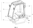
FIG. 2 is a schematic structural diagram of another hydrogen fuel cell forklift truck with a distribute architecture provided by an embodiment of the present application; -
FIG. 3 is a schematic structural diagram of an installation position of a hydrogen storage system of a hydrogen fuel cell forklift truck with a distribute architecture provided by an embodiment of the present application; -
FIG. 4 is a schematic diagram of a connection between a fuel cell and an energy storage system of a hydrogen fuel cell forklift truck with a distribute architecture provided by an embodiment of the present application; -
FIG. 5 is a schematic structural diagram of an energy storage system of a hydrogen fuel cell forklift truck with a distribute architecture provided by an embodiment of the present application; - Reference numerals in the drawings:
- 1 frame; 10 vehicle body; 11 balance weight; 111 air outlet; 12 protective cover; 13 roof guard frame; 14 leg; 15 mounting assembly; 151 mounting plate; 152 side plate; 16 fixing piece; 17 sliding block;
- 2 hydrogen storage system;
- 3 fuel cell;
- 4 cooling system; 41 cooling fan;
- 5 energy storage system; 51 handle; 52 charging port;
- 6 air intake system; 601 air suction pipe; 61 primary air filter; 602 air intake pipe; 62 secondary air filter;
- 7 cable.
- Technical solutions in the embodiments of the present disclosure are clearly and completely described below in conjunction with the drawings of the embodiments of the present disclosure. Apparently, the embodiments described in the following are only some embodiments of the present disclosure, rather than all of the embodiments.
- In order to make the person skilled in the art have a better understanding of solutions of the present disclosure, the present disclosure is described in further detail hereinafter, in conjunction with the drawings and embodiments.
- A hydrogen fuel cell forklift truck with a distribute architecture provided by the present application, as shown in
FIG. 1 of the description, including: aframe 1, ahydrogen storage system 2, afuel cell 3, acooling system 4 and anenergy storage system 5. Theframe 1 is the main part of the hydrogen fuel cell forklift truck with the distribute architecture, and thehydrogen storage system 2,fuel cell 3,cooling system 4 andenergy storage system 5 are all mounted based on theframe 1. - The
hydrogen storage system 2 is exposed to theframe 1. Of course, in order to protect thehydrogen storage system 2, a protective device such as aprotective cover 12 may also be provided on theframe 1. The protection device is detachable relative to theframe 1, and thehydrogen storage system 2 is also detachably connected with theframe 1, so that thehydrogen storage system 2 can be conveniently removed from theframe 1 and corresponding maintenance work can be performed on thehydrogen storage system 2. - The
fuel cell 3 is arranged on theframe 1 and located outside thehydrogen storage system 2. That is, thehydrogen storage system 2 and thefuel cell 3 are set in a separate type, and thehydrogen storage system 2 is connected with thefuel cell 3. Thefuel cell 3 utilizes the hydrogen in thehydrogen storage system 2 to perform a chemical reaction, thereby providing kinetic energy to the forklift. - The
cooling system 4 is arranged on theframe 1 and is located outside thefuel cell 3. Thecooling system 4 is connected to thefuel cell 3, and thefuel cell 3 is cooled by thecooling system 4; thehydrogen storage system 2, thefuel cell 3 and thecooling system 4 adopt a distributed architecture, and are respectively mounted at different positions of theframe 1, so that the installation and maintenance of each component can be implemented conveniently and quickly. - The
energy storage system 5 is arranged on theframe 1 and is located outside thefuel cell 3. Theenergy storage system 5 is connected to thefuel cell 3, and theenergy storage system 5 and thefuel cell 3 together provide kinetic energy and assist functions such as energy recovery and storage during vehicle braking. Theenergy storage system 5 is provided independently of thefuel cell 3, and the structural size of theenergy storage system 5 can be set according to requirements, which is not limited by the size of thefuel cell 3. - In some embodiments, referring to
FIG. 4 , thefuel cell 3 and theenergy storage system 5 are connected by acable 7. Thefuel cell 3 has a power generation device inside, so that thefuel cell 3 can be used to charge theenergy storage system 5, and thefuel cell 3 may also provide kinetic energy to the vehicle. - The
frame 1 is provided with asliding block 17, and theenergy storage system 5 may slide relative to thesliding block 17, that is, theenergy storage system 5 is movably arranged on theframe 1, so that it is convenient to pull theenergy storage system 5 out of theframe 1. - The
energy storage system 5 may be specifically a lithium battery, and is preferably arranged at the bottom of thevehicle frame 1, that is, below thefuel cell 3, and adopts a pull-out structure to facilitate the removal of theenergy storage system 5. Further, theenergy storage system 5 may be further provided with ahandle 51 and acharging port 52. - A pulling force can be conveniently applied to the
energy storage system 5 by using ahandle 51, that is, theenergy storage system 5 adopts a pull-out structure, which is more convenient to maintain; in addition, thecharging port 52 of theenergy storage system 5 can be used to recharge theenergy storage system 5 at any time. Meanwhile, because theenergy storage system 5 is placed outside thefuel cell 3, thus, theenergy storage system 5 may not be affected by the working temperature of thefuel cell 3, further improving the working efficiency of theenergy storage system 5. - The
frame 1 is be provided with abalance weight 11, which is usually located at the rear of theframe 1. The front part of theframe 1 is a fork, thehydrogen storage system 2 is located above thebalance weight 11, and thehydrogen storage system 2 includes a hydrogen storage bottle. The hydrogen storage bottle is located above thebalance weight 11, which is convenient to disassemble. - The
frame 1 may be further provided with aprotective cover 12. A space for accommodating thehydrogen storage system 2 is formed between theprotective cover 12 and theframe 1, and theprotective cover 12 is detachably connected to theframe 1; thehydrogen storage system 2 is protected by aprotective cover 12. When the hydrogen storage bottle needs annual inspection or maintenance, it is only necessary to remove theprotective cover 12, and then remove thehydrogen storage system 2 from theframe 1. In the process of removing thehydrogen storage system 2, the structure of thefuel cell 3 may not be greatly affected, which is very convenient. - Ventilation ports, hydrogen storage bottle exhaust ports and hydrogen filling ports, etc. can be designed on the
protective cover 12. Theprotective cover 12 can protect the hydrogen storage bottle from the impact of external forces, and can also ensure that hydrogen leakage is easy to diffuse, preventing potential safety hazards due to hydrogen accumulation. Hydrogenation ports can be arranged on the left and right sides, which is very convenient for hydrogenation. - Further, the
frame 1 is provided with a mountingassembly 15, and the mountingassembly 15 is detachably provided with a fixingpiece 16, and the fixingpiece 16 is used for fixing thehydrogen storage system 2 on the mountingassembly 15. - The mounting
assembly 15 includes a mountingplate 151 and twoside plates 152, the twoside plates 152 are placed vertically, the mountingplate 151 is located above the twoside plates 152 and is arranged horizontally. In order to improve the structural reliability, both the mountingplate 151 and the twoside plates 152 can be connected to theframe 1. A fixingpiece 16 is detachably provided on the mountingplate 151, thehydrogen storage system 2 is fixed by the fixingpiece 16, and thehydrogen storage system 2 is fixed on the mountingplate 151. - When the
hydrogen storage system 2 needs annual inspection or maintenance, first remove theprotective cover 12, then remove the fixingpiece 16 from the mountingplate 151, and finally remove thehydrogen storage system 2 from theframe 1, thus completing the removal of thehydrogen storage system 2. When thehydrogen storage system 2 is mounted, the sequence is reversed, and is not expanded here. - The
cooling system 4 is arranged below thehydrogen storage system 2, and thebalance weight 11 is provided with anair outlet 111; thecooling system 4 includes a coolingfan 41, the coolingfan 41 is disposed facing theair outlet 111, and the coolingfan 41 is used for convection heat dissipation with theair outlet 111. - The
cooling system 4 is placed below the rear of the forklift, that is, below thehydrogen storage system 2, and mainly includes the coolingfan 41, the cooling water tank and the expansion water tank and other module parts. The water inlet and outlet pipes of thecooling system 4 are respectively connected with the water inlet and outlet pipes of thefuel cell 3, and the exhaust pipes of thecooling system 4 are connected with the expansion water tank. The coolingfan 41 discharges air and dissipates heat through theair outlet 111 at the rear of thebalance weight 11. - The
cooling system 4 is fixed on theframe 1 and is located at the rear of theframe 1. Since there is no other heat source here and the internal ambient temperature is low, thebalance weight 11 is provided with anair outlet 111, and an air duct is designed on thebalance weight 11 and theframe 1 to make the heat dissipation effect better, thereby improving the working efficiency of thefuel cell 3; the wind direction of the coolingfan 41 is backward, which may not affect pedestrians on both sides of the forklift. The fan motor of the coolingfan 41 can be a non-explosion-proof motor, and there is no hydrogen accumulation at this position, so there is no safety hazard due to the accumulation of hydrogen. - The hydrogen fuel cell forklift truck with the distribute architecture provided according to the present application further includes an air intake system 6. The air intake system 6 is arranged on the
frame 1 and is exposed to theframe 1. The air intake system 6 is connected with thefuel cell 3, and is used for supplying air to make thefuel cell 3 react and provide kinetic energy. - The air intake system 6 includes an
air suction pipe 601 and anair intake pipe 602 that communicate with each other, and theair intake suction 601 is provided with asecondary air filter 62, two ends of theair intake pipe 602 are respectively connected with theair suction pipe 601 and thefuel cell 3, and theprimary air filter 61 is arranged at the connection between theair suction pipe 601 and theair intake pipe 602. It can be seen that theprimary air filter 61 and thesecondary air filter 62 are located outside thefuel cell 3. The air is secondarily filtered by theprimary air filter 61 and thesecondary air filter 62 to obtain clean air. The clean air enters thefuel cell 3 for reaction, generating kinetic energy. - The
frame 1 includes: avehicle body 10, aroof guard frame 13 andlegs 14. Ahydrogen storage system 2, afuel cell 3, acooling system 4 and anenergy storage system 5 are mounted on thevehicle body 10, and aroof guard frame 13 is located above thevehicle body 10; theleg 14 connects thevehicle body 10 with theroof guard frame 13, and theprimary air filter 61 is arranged at the position where theleg 14 is close to theroof guard frame 13. - The
secondary air filter 62 is fixed on the upper part of theleg 14, theprimary air filter 61 is fixed on the side of thefuel cell 3, and theprimary air filter 61 can be maintained by opening the cover, which is very convenient; in the process of use, firstly, the air is taken in through thesecondary air filter 62 on the upper part of theleg 14, and then the preliminarily filtered air reaches theprimary air filter 61 through theair suction pipe 601 for further filtration. Finally, clean air is input into thefuel cell 3 through theair intake pipe 602 to participate in the reaction, thereby improving the working efficiency and service life of thefuel cell 3. In addition, theprimary air filter 61 and thesecondary air filter 62 are externally arranged, which facilitates timely maintenance of the air filter and improves the working efficiency and service life of thefuel cell 3. - In the hydrogen fuel cell forklift truck with the distribute architecture designed in this way, some subsystems in the hydrogen fuel cell system that have great influence on each other are independently arranged, so that they can play a better role, improve the working efficiency and reliability of the whole vehicle, and prolong the working life of the whole vehicle.
- Specifically, the
hydrogen storage system 2 is externally arranged. When the hydrogen bottle needs to be disassembled during the annual inspection and maintenance of the hydrogen storage bottle, it is only necessary to disassemble theprotective cover 12 and the fixingpiece 16, which may not have a great impact on the structure of thefuel cell 3, so it is very convenient in terms of annual inspection and maintenance. Meanwhile, when the hydrogen in the hydrogen storage bottle leaks, it is easier to diffuse outward, which avoids the accumulation of hydrogen, and prevents potential safety hazards due to the accumulation of hydrogen. - When the
cooling system 4 is externally arranged, the ambient temperature of the cooling tank and the coolingfan 41 is lower than the internal ambient temperature of thefuel cell 3. Coupled with the optimized air duct, the whole cooling system has better cooling effect, which greatly improves the working efficiency and service life of the stack. The wind direction of thecooling system 4 is rearward, which may not affect the pedestrians on both sides of the forklift. - In this application, the
energy storage system 5 is externally arranged, thus theenergy storage system 5 may not be affected by the internal environment temperature of thefuel cell 3 when working, and the external arrangement has better heat dissipation effect. In addition, the use of the side-pull structure not only improves the working efficiency and service life of theenergy storage system 5, but also improves the maintenance speed of theenergy storage system 5. - The hydrogen fuel cell forklift truck with the distribute architecture provided by the present application has been described in detail hereinbefore. Principles and embodiments of the present disclosure are described herein through specific examples. Description of the above embodiments is merely used to facilitate understanding the method and concept of the present disclosure. It should be noted that several improvements and modifications can be made to the present application by those skilled in the art without departing from the subject-matter defined in the claims of the present application.
Claims (3)
- A hydrogen fuel cell forklift truck with a distribute architecture, comprising a frame (1), and, a hydrogen storage system (2), a fuel cell (3), a cooling system (4) and an energy storage system (5) arranged on the frame (1), the frame (1) is provided with a mounting assembly (15), the mounting assembly (15) comprises a mounting plate (151) and two side plates (152), the two side plates (152) are placed vertically, the mounting plate (151) is located above the two side plates (152) and is arranged horizontally, both the mounting plate (151) and the two side plates (152) are connected to the frame (1), and the mounting assembly (15) is detachably provided with a fixing piece (16), and the fixing piece (16) is used for fixing the hydrogen storage system (2) on the mounting assembly (15), a sliding block (17) is arranged on the frame (1), and the energy storage system (5) is slidable relative to the sliding block (17), the energy storage system (5) is further provided with a handle (51) and a charging port (52), whereinthe fuel cell (3) is connected with the hydrogen storage system (2) and the energy storage system (5) for charging the energy storage system (5) and providing kinetic energy;the hydrogen storage system (2) is located outside the fuel cell (3) and exposed to the frame (1) for supplying hydrogen to the fuel cell (3);the cooling system (4) is located outside the fuel cell (3) and connected to the fuel cell (3) for cooling the fuel cell (3); andthe energy storage system (5) is located outside the fuel cell (3) and connected to the fuel cell (3) for recovering braking energy and providing kinetic energy together with the fuel cell (3), wherein a balance weight (11) is provided on the frame (1), and the hydrogen storage system (2) is located above the balance weight (11),wherein the cooling system (4) is located below the hydrogen storage system (2), and the balance weight (11) is provided with an air outlet (111);wherein the cooling system (4) comprises:a heat dissipation fan (41), arranged facing the air outlet (111), for convection heat dissipation with the air outlet (111),the hydrogen fuel cell forklift truck with the distribute architecture further comprises:an air intake system (6) arranged on the frame (1) and exposed to the frame (1), wherein the air intake system is connected with the fuel cell (3), and is used for supplying air to make the fuel cell (3) react and provide kinetic energy,wherein the air intake system (6) comprises:a primary air filter (61);an air suction pipe (601) provided with a secondary air filter (62);an air intake pipe (602), wherein two ends of the air intake pipe are respectively connected with the air suction pipe (601) and the fuel cell (3), and the primary air filter (61) is arranged at the connection between the air suction pipe (601) and the air intake pipe (602),wherein the frame (1) comprises:a vehicle body (10) provided with a hydrogen storage system (2), a fuel cell (3), a cooling system (4) and an energy storage system (5);a roof guard frame (13) located above the vehicle body (10);a leg (14) connecting the vehicle body (10) and the roof guard frame (13), in which the secondary air filter (62) is arranged at a position of the leg (14) near the roof guard frame (13).
- The hydrogen fuel cell forklift truck with the distribute architecture according to claim 1, wherein the frame (1) is further provided with a protective cover (12) above the balance weight (11), a space for accommodating the hydrogen storage system (2) is formed between the protective cover (12) and the frame (1), and the protective cover (12) is detachably connected to the frame (1).
- The hydrogen fuel cell forklift truck with the distribute architecture according to claim 1 or 2, wherein the fuel cell (3) and the energy storage system (5) are connected by a cable (7).
Applications Claiming Priority (1)
| Application Number | Priority Date | Filing Date | Title |
|---|---|---|---|
| CN202210260908.0A CN114347810B (en) | 2022-03-17 | 2022-03-17 | Distributed architecture hydrogen fuel cell forklift |
Publications (2)
| Publication Number | Publication Date |
|---|---|
| EP4245715A1 EP4245715A1 (en) | 2023-09-20 |
| EP4245715B1 true EP4245715B1 (en) | 2024-07-17 |
Family
ID=81095058
Family Applications (1)
| Application Number | Title | Priority Date | Filing Date |
|---|---|---|---|
| EP22174136.6A Active EP4245715B1 (en) | 2022-03-17 | 2022-05-18 | Hydrogen fuel cell forklift truck with distributed architecture |
Country Status (3)
| Country | Link |
|---|---|
| US (1) | US12500294B2 (en) |
| EP (1) | EP4245715B1 (en) |
| CN (1) | CN114347810B (en) |
Family Cites Families (33)
| Publication number | Priority date | Publication date | Assignee | Title |
|---|---|---|---|---|
| DE10242619A1 (en) * | 2002-09-13 | 2004-03-18 | Still Gmbh | Truck |
| US7478698B2 (en) * | 2004-08-19 | 2009-01-20 | Honda Motor Co., Ltd. | Arrangement of intake and exhaust system components in a fuel cell powered vehicle |
| CN201325322Y (en) * | 2008-12-18 | 2009-10-14 | 重庆宗申技术开发研究有限公司 | Fixing device for air bottle of fork truck |
| CN102862491B (en) * | 2012-09-28 | 2014-09-03 | 引峰新能源科技(上海)有限公司 | Compact type fuel battery power supply system |
| WO2014123040A1 (en) * | 2013-02-06 | 2014-08-14 | 株式会社 豊田自動織機 | Structure for securing hydrogen tank in fuel-cell-type industrial vehicle and fuel cell unit |
| US11104231B2 (en) * | 2014-04-17 | 2021-08-31 | Michael Lynn Froelich | System for maintaining acceptable battery cycle life for electric-powered vehicles |
| CN106828067A (en) * | 2017-01-05 | 2017-06-13 | 北京新能源汽车股份有限公司 | Fuel cell electric vehicle |
| CN107161016A (en) * | 2017-04-17 | 2017-09-15 | 东风特汽(十堰)专用车有限公司 | Micro fuel cell logistic car complete vehicle structure is arranged |
| CN110799369B (en) * | 2017-06-30 | 2023-06-09 | 法国全耐塑料新能源公司 | Fuel cell architecture |
| CN207637907U (en) * | 2017-12-22 | 2018-07-20 | 新源动力股份有限公司 | Fuel cell power supply device for forklift |
| CN108502806A (en) * | 2018-05-21 | 2018-09-07 | 国祥航空有限公司 | Using hydrogen fuel as the fork truck of active force |
| JP7269117B2 (en) * | 2018-09-10 | 2023-05-08 | 株式会社豊田自動織機 | fuel cell industrial vehicle |
| JP2020117148A (en) * | 2019-01-25 | 2020-08-06 | ヤマハ発動機株式会社 | Open cabin electric vehicle |
| JP7366549B2 (en) * | 2019-01-25 | 2023-10-23 | ヤマハ発動機株式会社 | open cabin vehicle |
| KR102799711B1 (en) | 2019-11-12 | 2025-04-25 | 현대자동차주식회사 | Fuel cell vehicle |
| CN211000925U (en) * | 2019-12-03 | 2020-07-14 | 上海捷氢科技有限公司 | Fuel cell passenger car and hydrogen cylinder arrangement structure thereof |
| CN211813277U (en) * | 2019-12-20 | 2020-10-30 | 重庆宗申氢能源动力科技有限公司 | Fuel cell power supply system of forklift |
| CN113003489A (en) * | 2019-12-20 | 2021-06-22 | 重庆宗申氢能源动力科技有限公司 | Fuel cell power supply system of forklift |
| CN211617445U (en) * | 2020-01-07 | 2020-10-02 | 广州汽车集团股份有限公司 | Fuel cell system arrangement structure and car |
| CN211605293U (en) * | 2020-03-23 | 2020-09-29 | 山东明宇新能源技术有限公司 | Fuel cell for forklift |
| CN211605287U (en) * | 2020-03-26 | 2020-09-29 | 山东明宇新能源技术有限公司 | Hydrogen fuel cell loader |
| CN212303720U (en) * | 2020-04-07 | 2021-01-05 | 爱驰汽车有限公司 | Motor vehicle with fuel cell |
| CN112440764B (en) * | 2020-12-17 | 2024-06-04 | 安徽明天氢能科技股份有限公司 | Fuel cell system of passenger car |
| CN214356314U (en) * | 2021-02-08 | 2021-10-08 | 一汽解放汽车有限公司 | A fuel cell tractor |
| CN214477558U (en) * | 2021-02-24 | 2021-10-22 | 上海神力科技有限公司 | A dual fuel cell engine system applied to a heavy-duty vehicle and the heavy-duty vehicle |
| CN113022332B (en) * | 2021-03-26 | 2021-11-09 | 大连擎研科技有限公司 | System for high-power dual-fuel cell electric pile vehicle and using method thereof |
| CN113085590A (en) * | 2021-04-22 | 2021-07-09 | 上海氢雄信息科技有限公司 | Hydrogen fuel cell power system for forklift |
| CN215553625U (en) * | 2021-07-15 | 2022-01-18 | 海通科创(深圳)有限公司 | Hydrogen fuel cell tractor |
| CN113479075A (en) * | 2021-07-23 | 2021-10-08 | 淄博职业学院 | Light truck using hydrogen energy fuel cell system |
| CN113460918B (en) * | 2021-07-28 | 2024-08-30 | 天津新氢动力科技有限公司 | Fuel cell structure for forklift |
| CN113479130A (en) * | 2021-07-29 | 2021-10-08 | 三一汽车制造有限公司 | Vehicle and control method of vehicle |
| CN215731809U (en) * | 2021-09-07 | 2022-02-01 | 上海燃料电池汽车动力系统有限公司 | Integrated fuel cell power system for forklift |
| CN113829872B (en) * | 2021-10-28 | 2023-05-30 | 东风商用车有限公司 | Fuel cell truck adopting back and side hanging gas cylinders and mounting method |
-
2022
- 2022-03-17 CN CN202210260908.0A patent/CN114347810B/en active Active
- 2022-05-18 EP EP22174136.6A patent/EP4245715B1/en active Active
- 2022-05-26 US US17/826,156 patent/US12500294B2/en active Active
Also Published As
| Publication number | Publication date |
|---|---|
| CN114347810B (en) | 2022-07-29 |
| US20230299391A1 (en) | 2023-09-21 |
| US12500294B2 (en) | 2025-12-16 |
| EP4245715A1 (en) | 2023-09-20 |
| CN114347810A (en) | 2022-04-15 |
Similar Documents
| Publication | Publication Date | Title |
|---|---|---|
| US9543598B2 (en) | Fuel cell-powered motorcycle | |
| CN204537864U (en) | A kind of super capacitor module box body and use the super capacitor module of this casing | |
| Andaloro et al. | Design of a hybrid electric fuel cell power train for an urban bus | |
| CN217009303U (en) | battery pack | |
| US9293775B2 (en) | Compact safety type fuel cell system | |
| CN207225106U (en) | A kind of emergency power system based on detachable fuel cell | |
| CN216648375U (en) | Double-stack fuel cell packaging box structure | |
| CN216389519U (en) | Power battery heat radiation structure of dump truck in electric yard | |
| CN205985182U (en) | Power cell pack | |
| CN110588381B (en) | fuel cell vehicle | |
| US12500294B2 (en) | Hydrogen fuel cell forklift truck with distributed architecture | |
| CN216684064U (en) | Cooling system applied to pure electric special vehicle | |
| KR20240073313A (en) | Off-gas emission structure of battery pack case for electric vehicle | |
| CN207651629U (en) | A kind of electric automobile battery box radiator structure | |
| CN216928638U (en) | Hydrogen fuel cell forklift cooling system | |
| CN218750286U (en) | Radiator module | |
| EP4375103B1 (en) | New energy bus | |
| CN214378706U (en) | A vehicle power battery pack structure | |
| CN103216320B (en) | Power generating system and cabinet thereof | |
| US20250007070A1 (en) | Vehicle and power battery pack thereof | |
| CN209843906U (en) | Power battery integrated device for locomotive | |
| CN221978100U (en) | Liquid-cooled battery pack for energy storage | |
| CN212934672U (en) | Integral air inlet type cabinet | |
| CN220963487U (en) | Battery cooling structure of electric motorcycle | |
| CN222300793U (en) | Battery devices and power-consuming devices |
Legal Events
| Date | Code | Title | Description |
|---|---|---|---|
| PUAI | Public reference made under article 153(3) epc to a published international application that has entered the european phase |
Free format text: ORIGINAL CODE: 0009012 |
|
| STAA | Information on the status of an ep patent application or granted ep patent |
Free format text: STATUS: REQUEST FOR EXAMINATION WAS MADE |
|
| 17P | Request for examination filed |
Effective date: 20230713 |
|
| AK | Designated contracting states |
Kind code of ref document: A1 Designated state(s): AL AT BE BG CH CY CZ DE DK EE ES FI FR GB GR HR HU IE IS IT LI LT LU LV MC MK MT NL NO PL PT RO RS SE SI SK SM TR |
|
| GRAP | Despatch of communication of intention to grant a patent |
Free format text: ORIGINAL CODE: EPIDOSNIGR1 |
|
| STAA | Information on the status of an ep patent application or granted ep patent |
Free format text: STATUS: GRANT OF PATENT IS INTENDED |
|
| INTG | Intention to grant announced |
Effective date: 20231124 |
|
| GRAS | Grant fee paid |
Free format text: ORIGINAL CODE: EPIDOSNIGR3 |
|
| GRAA | (expected) grant |
Free format text: ORIGINAL CODE: 0009210 |
|
| STAA | Information on the status of an ep patent application or granted ep patent |
Free format text: STATUS: THE PATENT HAS BEEN GRANTED |
|
| AK | Designated contracting states |
Kind code of ref document: B1 Designated state(s): AL AT BE BG CH CY CZ DE DK EE ES FI FR GB GR HR HU IE IS IT LI LT LU LV MC MK MT NL NO PL PT RO RS SE SI SK SM TR |
|
| REG | Reference to a national code |
Ref country code: CH Ref legal event code: EP |
|
| REG | Reference to a national code |
Ref country code: DE Ref legal event code: R096 Ref document number: 602022004570 Country of ref document: DE |
|
| REG | Reference to a national code |
Ref country code: IE Ref legal event code: FG4D |
|
| REG | Reference to a national code |
Ref country code: LT Ref legal event code: MG9D |
|
| REG | Reference to a national code |
Ref country code: NL Ref legal event code: MP Effective date: 20240717 |
|
| PG25 | Lapsed in a contracting state [announced via postgrant information from national office to epo] |
Ref country code: PT Free format text: LAPSE BECAUSE OF FAILURE TO SUBMIT A TRANSLATION OF THE DESCRIPTION OR TO PAY THE FEE WITHIN THE PRESCRIBED TIME-LIMIT Effective date: 20241118 |
|
| REG | Reference to a national code |
Ref country code: AT Ref legal event code: MK05 Ref document number: 1703973 Country of ref document: AT Kind code of ref document: T Effective date: 20240717 |
|
| PG25 | Lapsed in a contracting state [announced via postgrant information from national office to epo] |
Ref country code: NL Free format text: LAPSE BECAUSE OF FAILURE TO SUBMIT A TRANSLATION OF THE DESCRIPTION OR TO PAY THE FEE WITHIN THE PRESCRIBED TIME-LIMIT Effective date: 20240717 |
|
| PG25 | Lapsed in a contracting state [announced via postgrant information from national office to epo] |
Ref country code: PT Free format text: LAPSE BECAUSE OF FAILURE TO SUBMIT A TRANSLATION OF THE DESCRIPTION OR TO PAY THE FEE WITHIN THE PRESCRIBED TIME-LIMIT Effective date: 20241118 Ref country code: NL Free format text: LAPSE BECAUSE OF FAILURE TO SUBMIT A TRANSLATION OF THE DESCRIPTION OR TO PAY THE FEE WITHIN THE PRESCRIBED TIME-LIMIT Effective date: 20240717 |
|
| PG25 | Lapsed in a contracting state [announced via postgrant information from national office to epo] |
Ref country code: NO Free format text: LAPSE BECAUSE OF FAILURE TO SUBMIT A TRANSLATION OF THE DESCRIPTION OR TO PAY THE FEE WITHIN THE PRESCRIBED TIME-LIMIT Effective date: 20241017 |
|
| PG25 | Lapsed in a contracting state [announced via postgrant information from national office to epo] |
Ref country code: GR Free format text: LAPSE BECAUSE OF FAILURE TO SUBMIT A TRANSLATION OF THE DESCRIPTION OR TO PAY THE FEE WITHIN THE PRESCRIBED TIME-LIMIT Effective date: 20241018 Ref country code: FI Free format text: LAPSE BECAUSE OF FAILURE TO SUBMIT A TRANSLATION OF THE DESCRIPTION OR TO PAY THE FEE WITHIN THE PRESCRIBED TIME-LIMIT Effective date: 20240717 Ref country code: PL Free format text: LAPSE BECAUSE OF FAILURE TO SUBMIT A TRANSLATION OF THE DESCRIPTION OR TO PAY THE FEE WITHIN THE PRESCRIBED TIME-LIMIT Effective date: 20240717 |
|
| PG25 | Lapsed in a contracting state [announced via postgrant information from national office to epo] |
Ref country code: BG Free format text: LAPSE BECAUSE OF FAILURE TO SUBMIT A TRANSLATION OF THE DESCRIPTION OR TO PAY THE FEE WITHIN THE PRESCRIBED TIME-LIMIT Effective date: 20240717 |
|
| PG25 | Lapsed in a contracting state [announced via postgrant information from national office to epo] |
Ref country code: LV Free format text: LAPSE BECAUSE OF FAILURE TO SUBMIT A TRANSLATION OF THE DESCRIPTION OR TO PAY THE FEE WITHIN THE PRESCRIBED TIME-LIMIT Effective date: 20240717 |
|
| PG25 | Lapsed in a contracting state [announced via postgrant information from national office to epo] |
Ref country code: IS Free format text: LAPSE BECAUSE OF FAILURE TO SUBMIT A TRANSLATION OF THE DESCRIPTION OR TO PAY THE FEE WITHIN THE PRESCRIBED TIME-LIMIT Effective date: 20241117 Ref country code: AT Free format text: LAPSE BECAUSE OF FAILURE TO SUBMIT A TRANSLATION OF THE DESCRIPTION OR TO PAY THE FEE WITHIN THE PRESCRIBED TIME-LIMIT Effective date: 20240717 |
|
| PG25 | Lapsed in a contracting state [announced via postgrant information from national office to epo] |
Ref country code: HR Free format text: LAPSE BECAUSE OF FAILURE TO SUBMIT A TRANSLATION OF THE DESCRIPTION OR TO PAY THE FEE WITHIN THE PRESCRIBED TIME-LIMIT Effective date: 20240717 |
|
| PG25 | Lapsed in a contracting state [announced via postgrant information from national office to epo] |
Ref country code: ES Free format text: LAPSE BECAUSE OF FAILURE TO SUBMIT A TRANSLATION OF THE DESCRIPTION OR TO PAY THE FEE WITHIN THE PRESCRIBED TIME-LIMIT Effective date: 20240717 Ref country code: RS Free format text: LAPSE BECAUSE OF FAILURE TO SUBMIT A TRANSLATION OF THE DESCRIPTION OR TO PAY THE FEE WITHIN THE PRESCRIBED TIME-LIMIT Effective date: 20241017 |
|
| PG25 | Lapsed in a contracting state [announced via postgrant information from national office to epo] |
Ref country code: RS Free format text: LAPSE BECAUSE OF FAILURE TO SUBMIT A TRANSLATION OF THE DESCRIPTION OR TO PAY THE FEE WITHIN THE PRESCRIBED TIME-LIMIT Effective date: 20241017 Ref country code: PL Free format text: LAPSE BECAUSE OF FAILURE TO SUBMIT A TRANSLATION OF THE DESCRIPTION OR TO PAY THE FEE WITHIN THE PRESCRIBED TIME-LIMIT Effective date: 20240717 Ref country code: NO Free format text: LAPSE BECAUSE OF FAILURE TO SUBMIT A TRANSLATION OF THE DESCRIPTION OR TO PAY THE FEE WITHIN THE PRESCRIBED TIME-LIMIT Effective date: 20241017 Ref country code: LV Free format text: LAPSE BECAUSE OF FAILURE TO SUBMIT A TRANSLATION OF THE DESCRIPTION OR TO PAY THE FEE WITHIN THE PRESCRIBED TIME-LIMIT Effective date: 20240717 Ref country code: IS Free format text: LAPSE BECAUSE OF FAILURE TO SUBMIT A TRANSLATION OF THE DESCRIPTION OR TO PAY THE FEE WITHIN THE PRESCRIBED TIME-LIMIT Effective date: 20241117 Ref country code: HR Free format text: LAPSE BECAUSE OF FAILURE TO SUBMIT A TRANSLATION OF THE DESCRIPTION OR TO PAY THE FEE WITHIN THE PRESCRIBED TIME-LIMIT Effective date: 20240717 Ref country code: GR Free format text: LAPSE BECAUSE OF FAILURE TO SUBMIT A TRANSLATION OF THE DESCRIPTION OR TO PAY THE FEE WITHIN THE PRESCRIBED TIME-LIMIT Effective date: 20241018 Ref country code: FI Free format text: LAPSE BECAUSE OF FAILURE TO SUBMIT A TRANSLATION OF THE DESCRIPTION OR TO PAY THE FEE WITHIN THE PRESCRIBED TIME-LIMIT Effective date: 20240717 Ref country code: ES Free format text: LAPSE BECAUSE OF FAILURE TO SUBMIT A TRANSLATION OF THE DESCRIPTION OR TO PAY THE FEE WITHIN THE PRESCRIBED TIME-LIMIT Effective date: 20240717 Ref country code: BG Free format text: LAPSE BECAUSE OF FAILURE TO SUBMIT A TRANSLATION OF THE DESCRIPTION OR TO PAY THE FEE WITHIN THE PRESCRIBED TIME-LIMIT Effective date: 20240717 Ref country code: AT Free format text: LAPSE BECAUSE OF FAILURE TO SUBMIT A TRANSLATION OF THE DESCRIPTION OR TO PAY THE FEE WITHIN THE PRESCRIBED TIME-LIMIT Effective date: 20240717 |
|
| PG25 | Lapsed in a contracting state [announced via postgrant information from national office to epo] |
Ref country code: RO Free format text: LAPSE BECAUSE OF FAILURE TO SUBMIT A TRANSLATION OF THE DESCRIPTION OR TO PAY THE FEE WITHIN THE PRESCRIBED TIME-LIMIT Effective date: 20240717 Ref country code: DK Free format text: LAPSE BECAUSE OF FAILURE TO SUBMIT A TRANSLATION OF THE DESCRIPTION OR TO PAY THE FEE WITHIN THE PRESCRIBED TIME-LIMIT Effective date: 20240717 Ref country code: SM Free format text: LAPSE BECAUSE OF FAILURE TO SUBMIT A TRANSLATION OF THE DESCRIPTION OR TO PAY THE FEE WITHIN THE PRESCRIBED TIME-LIMIT Effective date: 20240717 |
|
| REG | Reference to a national code |
Ref country code: DE Ref legal event code: R097 Ref document number: 602022004570 Country of ref document: DE |
|
| PG25 | Lapsed in a contracting state [announced via postgrant information from national office to epo] |
Ref country code: EE Free format text: LAPSE BECAUSE OF FAILURE TO SUBMIT A TRANSLATION OF THE DESCRIPTION OR TO PAY THE FEE WITHIN THE PRESCRIBED TIME-LIMIT Effective date: 20240717 |
|
| PG25 | Lapsed in a contracting state [announced via postgrant information from national office to epo] |
Ref country code: CZ Free format text: LAPSE BECAUSE OF FAILURE TO SUBMIT A TRANSLATION OF THE DESCRIPTION OR TO PAY THE FEE WITHIN THE PRESCRIBED TIME-LIMIT Effective date: 20240717 |
|
| PG25 | Lapsed in a contracting state [announced via postgrant information from national office to epo] |
Ref country code: SK Free format text: LAPSE BECAUSE OF FAILURE TO SUBMIT A TRANSLATION OF THE DESCRIPTION OR TO PAY THE FEE WITHIN THE PRESCRIBED TIME-LIMIT Effective date: 20240717 |
|
| PLBE | No opposition filed within time limit |
Free format text: ORIGINAL CODE: 0009261 |
|
| STAA | Information on the status of an ep patent application or granted ep patent |
Free format text: STATUS: NO OPPOSITION FILED WITHIN TIME LIMIT |
|
| 26N | No opposition filed |
Effective date: 20250422 |
|
| PGFP | Annual fee paid to national office [announced via postgrant information from national office to epo] |
Ref country code: DE Payment date: 20250513 Year of fee payment: 4 |
|
| PGFP | Annual fee paid to national office [announced via postgrant information from national office to epo] |
Ref country code: FR Payment date: 20250530 Year of fee payment: 4 |
|
| PG25 | Lapsed in a contracting state [announced via postgrant information from national office to epo] |
Ref country code: SE Free format text: LAPSE BECAUSE OF FAILURE TO SUBMIT A TRANSLATION OF THE DESCRIPTION OR TO PAY THE FEE WITHIN THE PRESCRIBED TIME-LIMIT Effective date: 20240717 |
|
| REG | Reference to a national code |
Ref country code: CH Ref legal event code: H13 Free format text: ST27 STATUS EVENT CODE: U-0-0-H10-H13 (AS PROVIDED BY THE NATIONAL OFFICE) Effective date: 20251223 |
|
| PG25 | Lapsed in a contracting state [announced via postgrant information from national office to epo] |
Ref country code: LU Free format text: LAPSE BECAUSE OF NON-PAYMENT OF DUE FEES Effective date: 20250518 |
|
| PG25 | Lapsed in a contracting state [announced via postgrant information from national office to epo] |
Ref country code: CH Free format text: LAPSE BECAUSE OF NON-PAYMENT OF DUE FEES Effective date: 20250531 |
|
| PG25 | Lapsed in a contracting state [announced via postgrant information from national office to epo] |
Ref country code: IT Free format text: LAPSE BECAUSE OF FAILURE TO SUBMIT A TRANSLATION OF THE DESCRIPTION OR TO PAY THE FEE WITHIN THE PRESCRIBED TIME-LIMIT Effective date: 20240717 |
|
| REG | Reference to a national code |
Ref country code: BE Ref legal event code: MM Effective date: 20250531 |
|
| PG25 | Lapsed in a contracting state [announced via postgrant information from national office to epo] |
Ref country code: MC Free format text: LAPSE BECAUSE OF FAILURE TO SUBMIT A TRANSLATION OF THE DESCRIPTION OR TO PAY THE FEE WITHIN THE PRESCRIBED TIME-LIMIT Effective date: 20240717 |
|
| PG25 | Lapsed in a contracting state [announced via postgrant information from national office to epo] |
Ref country code: IE Free format text: LAPSE BECAUSE OF NON-PAYMENT OF DUE FEES Effective date: 20250518 |
|
| PG25 | Lapsed in a contracting state [announced via postgrant information from national office to epo] |
Ref country code: BE Free format text: LAPSE BECAUSE OF NON-PAYMENT OF DUE FEES Effective date: 20250531 |