EP4245706A1 - Take-up device and take-up method - Google Patents
Take-up device and take-up method Download PDFInfo
- Publication number
- EP4245706A1 EP4245706A1 EP21891683.1A EP21891683A EP4245706A1 EP 4245706 A1 EP4245706 A1 EP 4245706A1 EP 21891683 A EP21891683 A EP 21891683A EP 4245706 A1 EP4245706 A1 EP 4245706A1
- Authority
- EP
- European Patent Office
- Prior art keywords
- yarn
- spool body
- shaped body
- reeling
- spool
- Prior art date
- Legal status (The legal status is an assumption and is not a legal conclusion. Google has not performed a legal analysis and makes no representation as to the accuracy of the status listed.)
- Pending
Links
Images


Classifications
-
- B—PERFORMING OPERATIONS; TRANSPORTING
- B65—CONVEYING; PACKING; STORING; HANDLING THIN OR FILAMENTARY MATERIAL
- B65H—HANDLING THIN OR FILAMENTARY MATERIAL, e.g. SHEETS, WEBS, CABLES
- B65H67/00—Replacing or removing cores, receptacles, or completed packages at paying-out, winding, or depositing stations
- B65H67/04—Arrangements for removing completed take-up packages and or replacing by cores, formers, or empty receptacles at winding or depositing stations; Transferring material between adjacent full and empty take-up elements
- B65H67/044—Continuous winding apparatus for winding on two or more winding heads in succession
- B65H67/052—Continuous winding apparatus for winding on two or more winding heads in succession having two or more winding heads arranged in parallel to each other
-
- B—PERFORMING OPERATIONS; TRANSPORTING
- B65—CONVEYING; PACKING; STORING; HANDLING THIN OR FILAMENTARY MATERIAL
- B65H—HANDLING THIN OR FILAMENTARY MATERIAL, e.g. SHEETS, WEBS, CABLES
- B65H54/00—Winding, coiling, or depositing filamentary material
- B65H54/56—Winding of hanks or skeins
- B65H54/58—Swifts or reels adapted solely for the formation of hanks or skeins
-
- B—PERFORMING OPERATIONS; TRANSPORTING
- B65—CONVEYING; PACKING; STORING; HANDLING THIN OR FILAMENTARY MATERIAL
- B65H—HANDLING THIN OR FILAMENTARY MATERIAL, e.g. SHEETS, WEBS, CABLES
- B65H54/00—Winding, coiling, or depositing filamentary material
- B65H54/56—Winding of hanks or skeins
- B65H54/62—Binding of skeins
-
- B—PERFORMING OPERATIONS; TRANSPORTING
- B65—CONVEYING; PACKING; STORING; HANDLING THIN OR FILAMENTARY MATERIAL
- B65H—HANDLING THIN OR FILAMENTARY MATERIAL, e.g. SHEETS, WEBS, CABLES
- B65H55/00—Wound packages of filamentary material
- B65H55/04—Wound packages of filamentary material characterised by method of winding
-
- B—PERFORMING OPERATIONS; TRANSPORTING
- B65—CONVEYING; PACKING; STORING; HANDLING THIN OR FILAMENTARY MATERIAL
- B65H—HANDLING THIN OR FILAMENTARY MATERIAL, e.g. SHEETS, WEBS, CABLES
- B65H57/00—Guides for filamentary materials; Supports therefor
-
- B—PERFORMING OPERATIONS; TRANSPORTING
- B65—CONVEYING; PACKING; STORING; HANDLING THIN OR FILAMENTARY MATERIAL
- B65H—HANDLING THIN OR FILAMENTARY MATERIAL, e.g. SHEETS, WEBS, CABLES
- B65H2701/00—Handled material; Storage means
- B65H2701/30—Handled filamentary material
- B65H2701/31—Textiles threads or artificial strands of filaments
Definitions
- the present disclosure relates to a reeling device and a reeling method. More particularly, the present disclosure relates to device and method for continuously and automatically forming a yarn-shaped body sent continuously from a preceding step, into a collection of the yarn-shaped body.
- the term "yarn-shaped body” refers to one or two or more solid yarns or one or two or more hollow yarns.
- a device for forming a collection of a yarn-shaped body employs a method of rotating a polygonal spool body to reel the yarn-shaped body and moving the yarn-shaped body to another spool body after the yarn-shaped body is reeled a predetermined number of times.
- PTL 1 discloses a device in which a plurality of spool bodies are supported to each have a rotation axis in parallel with a rotation member and the rotation member is rotated to replace a spool body located at a reeling position.
- PTL 2 discloses a device in which two spool bodies are arranged side by side so as to be coaxial to a rotation axis, and a yarn-shaped body is moved in the rotation axis direction.
- the two spool bodies need to be disposed face to face each other. On this occasion, a sufficient space cannot be secured in front of each spool body, thus resulting in problems in terms of arrangement of a device in a subsequent step, operability, and maintainability.
- a configuration is employed as means for solving this problem to temporarily convey, to a wide space, the spool body having the yarn-shaped body reeled the predetermined number of times, a device mechanism becomes complicated.
- a reeling device that reels a yarn-shaped body includes: a first spool body rotatable about a first rotation axis; a second spool body rotatable about a second rotation axis; and a yarn transfer portion capable of moving the yarn-shaped body between the first spool body and the second spool body, wherein the first rotation axis of the first spool body and the second rotation axis of the second spool body are parallel to each other, and a position of the first spool body around which the yarn-shaped body is to be wound and a position of the second spool body around which the yarn-shaped body is to be wound are arranged side by side on an imaginary plane orthogonal to the first rotation axis and the second rotation axis, and after a collection of the yarn-shaped body reeled a predetermined number of times is formed in the first spool body, a yarn-shaped body leading portion of the yarn transfer portion moves a yarn
- Each of the first spool body and the second spool body has a polygonal shape.
- Each vertex of the first spool body and the second spool body is provided with a vertex grasping mechanism that grasps the collection of the yarn-shaped body having been reeled.
- An internal grasping mechanism that grasps the yarn-shaped body sent from the yarn transfer portion is provided in each of the first spool body and the second spool body.
- the reeling device reels the yarn-shaped body by rotating the first spool body and the second spool body in opposite rotation directions when viewed in a direction in which each of the first rotation axis and the second rotation axis extends.
- Each of the first spool body and the second spool body is capable of simultaneously switching the reeling of the yarn-shaped body in two or more rows.
- a method of reeling a yarn-shaped body includes: a first step of reeling the yarn-shaped body in the first spool body; a second step of moving the yarn-shaped body to the second spool body by the yarn transfer portion; and a third step of reeling the yarn-shaped body in the second spool body.
- a reeling device and a reeling method so as to continuously and automatically form a yarn-shaped body sent from a preceding step into a collection of the yarn-shaped body while attaining such features that a ratio of wasted yarn is small, a device mechanism is not complicated, a device for a subsequent step is readily arranged, and operability and maintainability are excellent.
- a reeling device and a reeling method according to embodiments of the present disclosure will be described below with reference to figures.
- the scope of the present disclosure is not necessarily limited to the number, the amount, or the like unless otherwise stated particularly.
- the same components and corresponding components are denoted by the same reference characters, and the same explanation may not be described repeatedly. It has been initially expected to appropriately combine configurations in the embodiments.
- Fig. 1 is a schematic diagram for illustrating a configuration of a reeling unit 100 according to a first embodiment.
- Reeling unit 100 is constituted of a reeling device 1, a looseness absorption device 2, a tension control device 3, a film winding device 4, a yarn collection cutting device 5, and a yarn collection processing device 6.
- An operation of each device is controlled by a PLC (Programmable Logic Controller) (not shown).
- PLC Programmable Logic Controller
- Looseness absorption device 2 is a device that absorbs looseness of a yarn-shaped body sent from a yarn production device (not shown).
- the yarn-shaped body sent from the yarn production device is a bundle of a plurality of hollow yarns (for example, ten and several hollow yarns); however, the yarn-shaped body sent from the yarn production device may be one hollow yarn.
- the yarn-shaped body sent from the yarn production device may be one or two or more solid yarns.
- the yarn-shaped body is a reference amount of yarns sent from the yarn production device.
- Tension control device 3 is a device that controls an amount of feeding of the yarn-shaped body to reel the yarn-shaped body with a constant tension in reeling device 1.
- Reeling device 1 is a device that reels, using two spool bodies each having a polygonal shape, the yarn-shaped body having passed through tension control device 3.
- Film winding device 4 is a device that winds a film around a hollow yarn collection, which is a collection of the yarn-shaped body reeled by reeling device 1.
- Yarn collection cutting device 5 is a device that cuts, using a rounded cutting edge, the hollow yarn collection around which the film has been wound.
- Yarn collection processing device 6 is an device that performs processes such as: a process of supplying a film to film winding device 4; a process of moving film winding device 4 to a position of a spool body; and a process of fixing (attaching a tape to) overlapping portions of the film wound around the hollow yarn collection.
- FIG. 2 is a schematic diagram for illustrating an operation of reeling device 1 according to the first embodiment
- Fig. 3 is a front view of reeling device 1 according to the first embodiment
- Fig. 4 is a schematic diagram for illustrating the operation of reeling device 1 according to the first embodiment when viewed in plan.
- Reeling device 1 includes: a left spool body 10L serving as a first spool body and provided on the left side when viewed in the front view; and a right spool body 10R serving as a second spool body and provided on the right side when viewed in the front view. Between left spool body 10L and right spool body 10R, a yarn transfer mechanism 20 is disposed to serve as a yarn transfer portion capable of moving yarn-shaped body 7 in the leftward/rightward direction. Each of left spool body 10L and right spool body 10R is operated by a servo motor provided with a speed reducer (not shown).
- internal clamping mechanisms 30 each serving as an internal grasping mechanism are provided to grasp yarn-shaped body 7 having been moved by yarn transfer mechanism 20.
- Two internal clamping mechanisms 30 are disposed in each of left spool body 10L and right spool body 10R at positions facing each other.
- One internal clamping mechanism 30 may be disposed in each of left spool body 10L and right spool body 10R; however, consideration needs to be taken to achieve a weight balance of the spool body.
- the number of the internal grasping mechanisms (internal clamping mechanisms 30) disposed therein may be the same number as the number of (the vertices of) the polygon.
- Reeling device 1 is operated in the order of Fig. 2 (A) to Fig. 2 (E) .
- reeling device 1 moves yarn transfer mechanism 20 grasping yarn-shaped body 7 from a center position to left spool body 10L.
- Yarn-shaped body 7 having been moved to left spool body 10L by yarn transfer mechanism 20 is grasped by internal clamping mechanism 30 of left spool body 10L.
- yarn transfer mechanism 20 releases yarn-shaped body 7 having been grasped by yarn transfer mechanism 20, and is moved to the center position.
- reeling device 1 reels yarn-shaped body 7 around the vertexes of left spool body 10L by rotating left spool body 10L rightward (clockwise).
- Reeling device 1 stops the rotation after reeling yarn-shaped body 7 a predetermined number of times in left spool body 10L so as to form a hollow yarn collection 70 that is a collection of the yarn-shaped body reeled the predetermined number of times.
- Hollow yarn collection 70 is, for example, a collection of a hollow yarn reeled about 10,000 times and used as a product.
- Reeling device 1 then grasps hollow yarn collection 70 at the vertexes of left spool body 10L using vertex clamping mechanisms 11 each serving as a vertex grasping mechanism. Details of vertex clamping mechanisms 11 will be described later.
- Fig. 2 (C) shows only a vertex clamping mechanism 11 at a position at which yarn transfer mechanism 20 grasps among vertex clamping mechanisms 11 located at the positions of the vertexes.
- reeling device 1 moves yarn transfer mechanism 20 from the center position to left spool body 10L.
- Yarn transfer mechanism 20 grasps yarn-shaped body 7 and cuts yarn-shaped body 7 at a position below the grasping position.
- reeling device 1 moves yarn transfer mechanism 20 grasping yarn-shaped body 7, from left spool body 10L to right spool body 10R.
- Yarn-shaped body 7 having been moved to right spool body 10R by yarn transfer mechanism 20 is grasped by internal clamping mechanism 30 of right spool body 10R. After yarn-shaped body 7 is grasped by internal clamping mechanism 30 of right spool body 10R, yarn transfer mechanism 20 releases yarn-shaped body 7 having been grasped by yarn transfer mechanism 20, and is moved to the center position.
- reeling device 1 reels yarn-shaped body 7 around the vertexes of right spool body 10R by rotating right spool body 10R leftward (counterclockwise).
- Reeling device 1 stops the rotation after reeling yarn-shaped body 7 a predetermined number of times in right spool body 10R so as to form a hollow yarn collection 70.
- Reeling device 1 forms hollow yarn collections 70 in left spool body 10L and right spool body 10R by the series of operations shown in Figs. 2 (A) to 2 (E).
- left spool body 10L and right spool body 10R are disposed adjacent to each other on the front side with respect to a wall surface 50 when viewed in a front view.
- Vertex clamping mechanisms 11 are provided at the respective vertexes of each of the regular hexagonal shape of left spool body 10L and the regular hexagonal shape of right spool body 10R.
- Internal clamping mechanisms 30 are disposed at positions facing each other in each of left spool body 10L and right spool body 10R.
- each of left spool body 10L and right spool body 10R six arm portions 10Y are connected to a main body portion 10X.
- Notches 10Z are formed in main body portion 10X at positions corresponding to the positions of arm portions 10Y having internal clamping mechanisms 30 disposed thereon.
- Each of notches 10Z prevents blocking of movement of yarn transfer mechanism 20 when yarn transfer mechanism 20 is translated between left spool body 10L and right spool body 10R to transfer yarn-shaped body 7 to internal clamping mechanism 30.
- Yarn-shaped body 7 to be reeled by reeling device 1 is adjusted by tension control device 3 so as to be reeled with a constant tension.
- left spool body 10L is rotated about a first rotation axis CL1
- right spool body 10R is rotated about a second rotation axis CL2.
- First rotation axis CL1 of left spool body 10L and second rotation axis CL2 of right spool body 10R are parallel to each other.
- a first groove portion 11b which is a position of left spool body 10L around which yarn-shaped body 7 is to be wound
- a first groove portion 11b which is a position of right spool body 10R around which yarn-shaped body 7 is to be wound, are arranged side by side along a first imaginary plane VS1 orthogonal to first rotation axis CL1 and second rotation axis CL2.
- a second groove portion 11e which is a position of left spool body 10L around which yarn-shaped body 7 is to be wound, and a second groove portion 11e, which is a position of right spool body 10R around which yarn-shaped body 7 is to be wound, are arranged side by side along a second imaginary plane VS2 orthogonal to first rotation axis CL1 and second rotation axis CL2.
- First imaginary plane VS1 and second imaginary plane VS2 are located in a direction perpendicular to a plane of sheet.
- left spool body 10L and right spool body 10R are arranged in rows orthogonal to first imaginary plane VS1 and second imaginary plane VS2.
- Yarn transfer mechanism 20 includes a first yarn transfer portion 20F located on the front side and a second yarn transfer portion 20R located on the rear side.
- First yarn transfer portion 20F includes a first right leading portion 20d and a first left leading portion 20f.
- Second yarn transfer portion 20R includes a second right leading portion 20h and a second left leading portion 20j.
- First yarn transfer portion 20F is moved leftward/rightward along first imaginary plane VS1.
- Second yarn transfer portion 20R is moved leftward/rightward along second imaginary plane VS2.
- Vertex clamping mechanism 11 includes a first vertex clamping portion 11F located on the front side and a second vertex clamping portion 11R located on the rear side.
- reeling device 1 grasps hollow yarn collection 70 at first vertex clamping portion 11F and second vertex clamping portion 11R located on the rear side.
- yarn transfer mechanism 20 grasps yarn-shaped body 7 sent from the tension control device 3 side and cuts yarn-shaped body 7.
- First yarn transfer portion 20F of yarn transfer mechanism 20 is moved leftward/rightward along first imaginary plane VS1.
- Second yarn transfer portion 20R of yarn transfer mechanism 20 is moved leftward/rightward along second imaginary plane VS2.
- each of left spool body 10L and right spool body 10R can simultaneously reel yarn-shaped body 7 in two rows.
- yarn transfer mechanism 20 can simultaneously move yarn-shaped body 7 in two rows.
- reeling device 1 can simultaneously switch the reeling of yarn-shaped body 7. It should be noted that reeling device 1 may be configured to simultaneously switch the reeling of yarn-shaped body 7 in three or more rows.
- Fig. 5 is a diagram for illustrating vertex clamping mechanism 11 in a non-fixed state in the first embodiment
- Fig. 6 is a diagram for illustrating vertex clamping mechanism 11 in a fixed state in the first embodiment.
- vertex clamping mechanism 11 includes: a vertex clamping main body portion 11a connected to each of arm portion 10Y of left spool body 10L and arm portion 10Y of right spool body 10R; a first vertex clamping portion 11F located on the front side; and a second vertex clamping portion 11R located on the rear side.
- First vertex clamping portion 11F includes: first groove portion 11b; a front vertex clamping member 11c rotatable about a first supporting portion 11d; and a front auxiliary member 11t rotatable about first supporting portion 11d.
- Second vertex clamping portion 11R includes: second groove portion 11e; a rear vertex clamping member 11f rotatable about a second supporting portion 11g; and a rear auxiliary member 11u rotatable about second supporting portion 11g.
- two tension springs are disposed at a lower portion on the rear surface side.
- a tension spring located on the front side is connected at a position below front auxiliary member 11t, and is disposed to be rotatable about a third supporting portion 11p.
- a tension spring located on the rear side is connected at a position below rear auxiliary member 11u, and is disposed to be rotatable about a fourth supporting portion 11s.
- Vertex clamping mechanism 11 includes: a first locking member 11q rotatable about third supporting portion 11p; a second locking member 11r rotatable about fourth supporting portion 11s; and a vertex stem portion 11o that connects between first locking member 11q and second locking member 11r.
- Vertex clamping mechanism 11 includes: a clamping cylinder 11h disposed inside wall surface 50; and a release cylinder 11i disposed inside wall surface 50.
- Clamping cylinder 11h includes a first pushing member 11j that can protrude frontward.
- Release cylinder 11i includes a second pushing member 11k that can protrude frontward.
- Second locking member 11r includes: a first receiving member 11m to be brought into abutment with first pushing member 11j having protruded frontward; and a second receiving member 11n to be brought into abutment with second pushing member 11k having protruding frontward.
- Vertex clamping mechanism 11 grasping hollow yarn collection 70; and an operation of vertex clamping mechanism 11 releasing hollow yarn collection 70 having been grasped by vertex clamping mechanism 11.
- Vertex clamping mechanism 11 operates clamping cylinder 11h in the non-fixed state shown in Fig. 5 so as to protrude first pushing member 11j frontward.
- First pushing member 11j is brought into abutment with first receiving member 11m by the frontward movement.
- first receiving member 11m connected to second locking member 11r is moved frontward with respect to fourth supporting portion 11s.
- First pushing member 11j pushes first receiving member 11m and then returns to the initial position.
- second receiving member 11n connected to second locking member 11r is moved rearward by an distance corresponding to a distance in which first receiving member 11m has been moved frontward.
- vertex stem portion 11o connected to second locking member 11r is moved rearward with respect to fourth supporting portion 11s.
- first locking member 11q connected to vertex stem portion 11o is moved rearward with respect to third supporting portion 11p.
- vertex clamping mechanism 11 by the series of operations of first locking member 11q and second locking member 11r, the tension spring located on the front side and the tension spring located on the rear side are moved upward while being rotated.
- Front auxiliary member 11t is moved upward with respect to first supporting portion 11d by the tension of the tension spring located on the front side.
- front vertex clamping member 11c is moved from the non-fixed position shown in Fig. 5 to the fixed position shown in Fig. 6 with respect to first supporting portion 11d.
- Rear auxiliary member 11u is moved upward with respect to second supporting portion 11g by the tension of the tension spring on the rear side.
- rear vertex clamping member 11f is moved from the non-fixed position shown in Fig. 5 to the fixed position shown in Fig. 6 with respect to second supporting portion 11g. Since each of front vertex clamping member 11c and rear vertex clamping member 11f is moved from the non-fixed position to the fixed position, vertex clamping mechanism 11 can grasp hollow yarn collection 70 at two positions in the frontward/rearward direction.
- Vertex clamping mechanism 11 performs the operation of releasing hollow yarn collection 70 having been grasped by vertex clamping mechanism 11, in the following order. Vertex clamping mechanism 11 operates release cylinder 11i in the fixed state shown in Fig. 6 to protrude second pushing member 11k frontward. Second pushing member 11k is brought into abutment with second receiving member 11n by the frontward movement. As shown in Fig. 5 , second receiving member 11n connected to second locking member 11r is moved frontward with respect to fourth supporting portion 11s.
- Second pushing member 11k pushes second receiving member 11n and then returns to the initial position.
- first receiving member 11m connected to second locking member 11r is moved rearward by a distance corresponding to a distance in which second receiving member 11n has been moved frontward.
- vertex stem portion 11o connected to second locking member 11r is moved frontward with respect to fourth supporting portion 11s.
- first locking member 11q connected to vertex stem portion 11o is moved frontward with respect to third supporting portion 11p.
- vertex clamping mechanism 11 by the series of operations of first locking member 11q and second locking member 11r, the tension spring located on the front side and the tension spring located on the rear side are moved downward while being rotated.
- Front auxiliary member 11t is moved downward with respect to first supporting portion 11d by the tension of the tension spring located on the front side.
- front vertex clamping member 11c is moved from the fixed position shown in Fig. 6 to the non-fixed position shown in Fig. 5 with respect to first supporting portion 11d.
- Rear auxiliary member 1 1u is moved downward with respect to second supporting portion 11g by the tension of the tension spring located on the rear side.
- rear vertex clamping member 11f is moved from the fixed position shown in Fig. 6 to the non-fixed position shown in Fig. 5 with respect to second supporting portion 11g.
- front vertex clamping member 11c and rear vertex clamping member 11f are moved from the fixed position to the non-fixed position, thereby releasing hollow yarn collection 70 at the two positions in the frontward/rearward direction.
- Fig. 7 is a plan view of yarn transfer mechanism 20 according to the first embodiment.
- Fig. 8 is a side view of yarn transfer mechanism 20 according to the first embodiment.
- Yarn transfer mechanism 20 includes: a main body portion 20a extending from wall surface 50 toward the front side; first yarn transfer portion 20F located on the front side; and second yarn transfer portion 20R located on the rear side.
- First yarn transfer portion 20F includes a first right guiding portion 20c, first right leading portion 20d, a first left guiding portion 20e, and first left leading portion 20f.
- Second yarn transfer portion 20R includes a second right guiding portion 20g, second right leading portion 20h, a second left guiding portion 20i, and second left leading portion 20j.
- Yarn transfer mechanism 20 is operated by a robot cylinder disposed in wall surface 50.
- yarn transfer mechanism 20 When yarn transfer mechanism 20 is moved rightward, yarn-shaped body 7 located on frontward on the right side is moved along first right guiding portion 20c and is led to first right leading portion 20d.
- yarn transfer mechanism 20 When yarn transfer mechanism 20 is moved leftward, yarn-shaped body 7 located frontward on the left side is moved along first left guiding portion 20e and is led to first left leading portion 20f.
- yarn transfer mechanism 20 When yarn transfer mechanism 20 is moved rightward, yarn-shaped body 7 located rearward on the right side is moved along second right guiding portion 20g and is led to second right leading portion 20h.
- yarn transfer mechanism 20 When yarn transfer mechanism 20 is moved leftward, yarn-shaped body 7 located rearward on the left side is moved along second left guiding portion 20i and is led to second left leading portion 20j.
- Yarn transfer mechanism 20 includes a cylinder portion 20k, and a yarn transfer stem portion 20q connected to cylinder portion 20k.
- First yarn transfer portion 20F includes a first fixed clamping portion 20m, a first movable clamping portion 20n, and a first yarn cutting edge 20p.
- Second yarn transfer portion 20R includes a second fixed clamping portion 20r, a second movable clamping portion 20s, and a second yarn cutting edge 20t.
- Yarn transfer stem portion 20q is operated integrally with first movable clamping portion 20n, first yarn cutting edge 20p, second movable clamping portion 20s, and second yarn cutting edge 20t.
- Yarn transfer mechanism 20 performs the operation of grasping and moving yarn-shaped body 7 in the following order. After hollow yarn collection 70 is formed in left spool body 10L, yarn transfer mechanism 20 is moved from the center position to a vertex position of left spool body 10L in the horizontal direction. Before moving yarn transfer mechanism 20, the rotation of left spool body 10L is stopped at an appropriate position detected by a sensor that detects an angle of the rotation axis of left spool body 10L disposed inside wall surface 50.
- yarn transfer mechanism 20 grasps yarn-shaped body 7 sent from tension control device 3 and having reached the vertex position of left spool body 10L.
- Yarn transfer mechanism 20 can grasp yarn-shaped body 7 by an operation in which first movable clamping portion 20n and second movable clamping portion 20s are moved rearward as yarn transfer stem portion 20q is moved rearward by controlling cylinder portion 20k.
- Yarn-shaped body 7 grasped is cut by first yarn cutting edge 20p and second yarn cutting edge 20t at a position below the grasping position.
- Yarn transfer mechanism 20 is horizontally moved while grasping yarn-shaped body 7, and transfers yarn-shaped body 7 to internal clamping mechanism 30 of right spool body 10R.
- the rotation of right spool body 10R is stopped at an appropriate position detected by a sensor that detects an angle of the rotation axis of right spool body 10R disposed inside wall surface 50.
- the appropriate position is a position at which internal clamping mechanism 30 of right spool body 10R can grasp yarn-shaped body 7 conveyed from yarn transfer mechanism 20.
- FIG. 9 is a diagram for illustrating internal clamping mechanism 30 in the fixed state according to the first embodiment.
- Internal clamping mechanism 30 includes: a pair of coupling portions 30f fixed to arm portions 10Y of left spool body 10L and right spool body 10R; a main body portion 30a connected to the pair of coupling portions 30f; a first internal clamping portion 30F located on the front side; a second internal clamping portion 30R located on the rear side; and an internal stem portion 30g.
- First internal clamping portion 30F includes a first fixed clamping portion 30c, a first movable clamping portion 30b, and a first spring portion 30m.
- Second internal clamping portion 30R includes a second fixed clamping portion 30e, a second movable clamping portion 30d, and a second spring portion 30n.
- Internal stem portion 30g is operated integrally with first movable clamping portion 30b and second movable clamping portion 30d.
- Internal clamping mechanism 30 includes a cylinder 30h disposed inside wall surface 50. Cylinder 30h includes a pushing member 30i that can protrude frontward.
- Internal clamping mechanism 30 performs an operation of grasping yarn-shaped body 7 in the following order.
- Internal clamping mechanism 30 operates cylinder 30h in the fixed state shown in Fig. 9 to protrude pushing member 30i frontward.
- Pushing member 30i is brought into abutment with an end portion of internal stem portion 30g by the frontward movement.
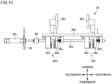
- first internal clamping portion 30F internal stem portion 30g is moved frontward against a restoring force of first spring portion 30m, thereby forming a clearance between first fixed clamping portion 30c and first movable clamping portion 30b as shown in Fig. 10 .
- second internal clamping portion 30R internal stem portion 30g is moved frontward against a restoring force of second spring portion 30n, thereby forming a clearance between second fixed clamping portion 30e and second movable clamping portion 30d as shown in Fig. 10 .
- Yarn transfer mechanism 20 moves yarn-shaped body 7 to the clearance formed in each of first internal clamping portion 30F and second movable clamping portion 30d.
- Internal clamping mechanism 30 operates cylinder 30h to return pushing member 30i rearward.
- Internal clamping mechanism 30 is changed from the non-fixed state shown in Fig. 10 to the fixed state shown in Fig. 9 by the restoring forces of first spring portion 30m and second spring portion 30n. Since internal clamping mechanism 30 is brought into the fixed state, internal clamping mechanism 30 grasps yarn-shaped body 7 at each of first internal clamping portion 30F and second internal clamping portion 30R.
- the reeling method includes: a first step of reeling yarn-shaped body 7 in left spool body 10L; a second step of moving yarn-shaped body 7 to right spool body 10R by yarn transfer mechanism 20; and a third step of reeling yarn-shaped body 7 in right spool body 10R.
- the first step includes a step of moving, at the time of starting the reeling, yarn transfer mechanism 20 grasping yarn-shaped body 7 from the center position to left spool body 10L, and grasping the moved yarn-shaped body 7 by internal clamping mechanism 30 of left spool body 10L.
- the first step includes a step of releasing, after yarn-shaped body 7 is grasped by internal clamping mechanism 30 of left spool body 10L, yarn-shaped body 7 having been grasped by yarn transfer mechanism 20, and moving yarn transfer mechanism 20 to the center position.
- the first step includes a step of reeling yarn-shaped body 7 around the vertexes of left spool body 10L a predetermined number of times by rotating left spool body 10L rightward (clockwise), so as to form hollow yarn collection 70 and then stopping the rotation.
- the second step includes a step of moving yarn transfer mechanism 20 from the center position to left spool body 10L, grasping yarn-shaped body 7, and cutting yarn-shaped body 7 at a position below the grasping position.
- the second step includes a step of grasping yarn-shaped body 7 by yarn transfer mechanism 20 and moving yarn transfer mechanism 20 from left spool body 10L to right spool body 10R.
- the third step includes a step of grasping, by internal clamping mechanism 30 of right spool body 10R, yarn-shaped body 7 having been moved to right spool body 10R by yarn transfer mechanism 20.
- the third step includes a step of releasing, after yarn-shaped body 7 is grasped by internal clamping mechanism 30 of right spool body 10R, yarn-shaped body 7 having been grasped by yarn transfer mechanism 20, and moving yarn transfer mechanism 20 to the center position.
- the third step includes a step of reeling yarn-shaped body 7 around the vertexes of right spool body 10R a predetermined number of times by rotating right spool body 10R leftward (counterclockwise), so as to form hollow yarn collection 70, and then stopping the rotation.
- Reeling device 1 includes: left spool body 10L rotatable about first rotation axis CL1; right spool body 10R rotatable about second rotation axis CL2; and yarn transfer mechanism 20 capable of moving yarn-shaped body 7 between left spool body 10L and right spool body 10R.
- First rotation axis CL1 of left spool body 10L and second rotation axis CL2 of right spool body 10R are parallel to each other.
- First groove portion 11b which is a position of left spool body 10L around which yarn-shaped body 7 is to be wound
- first groove portion 11b which is a position of right spool body 10R around which yarn-shaped body 7 is to be wound
- Second groove portion 11e which is a position of left spool body 10L around which yarn-shaped body 7 is to be wound
- second groove portion 11e which is a position of right spool body 10R around which yarn-shaped body 7 is to be wound, are arranged side by side along second imaginary plane VS2 orthogonal to first rotation axis CL1 and second rotation axis CL2.
- First yarn transfer portion 20F is moved leftward/rightward along first imaginary plane VS1.
- Second yarn transfer portion 20R is moved leftward/rightward along second imaginary plane VS2.
- first right leading portion 20d of first yarn transfer portion 20F moves yarn-shaped body 7 from left spool body 10L to right spool body 10R along first imaginary plane VS1.
- Reeling device 1 is configured such that left spool body 10L and right spool body 10R are arranged in rows orthogonal to first imaginary plane VS1 and second imaginary plane VS2, and yarn transfer mechanism 20 is moved between left spool body 10L and right spool body 10R.
- reeling device 1 does not have a rotation member that supports a spool body, the spool body is designed to be large readily, with the result that a ratio of wasted yarn can be reduced.
- reeling device 1 since a sufficient space can be secured in front of the spool body in reeling device 1, a device for a subsequent step is readily disposed (without employing a configuration for temporarily conveying, to a wide space, a spool body having yarn-shaped body 7 reeled a predetermined number of times), and operability and maintainability are excellent. Further, reeling device 1 can continuously and automatically form, into hollow yarn collection 70, yarn-shaped body 7 sent from the preceding step.
- Each of left spool body 10L and right spool body 10R has a hexagonal shape.
- internal clamping mechanism 30 can be disposed on an internal side with respect to the reeling position as compared with a two-point reeling method or a circular reeling method, thereby reducing such a risk that a starting portion of yarn-shaped body 7 is introduced into a product.
- the number of the vertexes of the polygon is preferably large in the reeling device; however, when the number of the vertexes of the polygon is too large, there is a risk of occurrence of the following problem or the like: yarn-shaped body 7 is brought into contact with the spool body when taking the position shown in Fig. 2 (D) , with the result that the yarn is cut.
- reeling device 1 employs the hexagonal shape as an appropriate shape in which yarn-shaped body 7 is not brought into contact with the spool body and the number of sides is as large as possible.
- vertex clamping mechanism 11 is provided to grasp hollow yarn collection 70 having been reeled. Therefore, reeling device 1 can appropriately grasp hollow yarn collection 70 at each vertex.
- Internal clamping mechanism 30 that grasps yarn-shaped body 7 sent from yarn transfer mechanism 20 is provided in each of left spool body 10L and right spool body 10R. Therefore, reeling device 1 can appropriately grasp yarn-shaped body 7 in each of left spool body 10L and right spool body 10R.
- Reeling device 1 reels yarn-shaped body 7 by rotating left spool body 10L and right spool body 10R in opposite directions when viewed in the direction in which each of first rotation axis CL1 and second rotation axis CL2 extends. Therefore, reeling device 1 can transfer yarn-shaped body 7 from left spool body 10L to right spool body 10R in a short moving distance. Further, since reeling device 1 can reel yarn-shaped body 7 in an internal direction, yarn-shaped body 7 can be reeled suitably without damaging yarn-shaped body 7.
- Reeling device 1 is capable of simultaneously switching the reeling of yarn-shaped body 7 in two or more rows.
- reeling device 1 left spool body 10L and right spool body 10 are arranged in rows orthogonal to first imaginary plane VS1 and second imaginary plane VS2. Therefore, in reeling device 1, since no jump stitch is not generated at the time of the simultaneous switching of yarn-shaped body 7 in the plurality of rows, wasted yarns are not increased, with the result that an interval between the spool bodies can be appropriately designed. Accordingly, reeling device 1 can increase production efficiency when forming hollow yarn collection 70.
- the reeling method includes: the first step of reeling yarn-shaped body 7 in left spool body 10L; the second step of moving yarn-shaped body 7 to right spool body 10R by yarn transfer mechanism 20; and the third step of reeling yarn-shaped body 7 in right spool body 10R.
- a ratio of wasted yarn can be reduced, a device mechanism can be simplified, a device for a subsequent step can be disposed readily, and operability and maintainability can be improved.
- yarn-shaped body 7 sent from the preceding step can be continuously and automatically formed into hollow yarn collection 70.
- a spool body having a polygonal shape other than the spool body having the hexagonal shape may be used.
- a two-point spool body that reels at two points may be used.
- a spool body having a circular shape may be used.
- each of left spool body 10L and right spool body 10R is capable of simultaneously reeling yarn-shaped body 7 in two rows.
- Each of left spool body 10L and right spool body 10R may be configured to reel yarn-shaped body 7 in one row.
- Each of left spool body 10L and right spool body 10R may be configured to simultaneously reel yarn-shaped body 7 in three or more rows.
- Yarn-shaped body 7 may be reeled in the following order: yarn-shaped body 7 is reeled in right spool body 10R, yarn-shaped body 7 is then moved to left spool body 10L by yarn transfer mechanism 20, and yarn-shaped body 7 is reeled in left spool body 10L.
- 1 reeling device; 2: looseness absorption device; 3: tension control device; 4: film winding device; 5: yarn collection cutting device; 6: yarn collection processing device; 7: yarn-shaped body; 10L: left spool body; 10R: right spool body; 10X: main body portion; 10Y: arm portion; 10Z: notch; 11: vertex clamping mechanism; 11F: first vertex clamping portion; 11R: second vertex clamping portion; 20: yarn transfer mechanism; 20F: first yarn transfer portion; 20R: second yarn transfer portion; 30: internal clamping mechanism; 30F: first internal clamping portion; 30R: second internal clamping portion; 50: wall surface; 70: hollow yarn collection; 100: reeling unit; CL1: first rotation axis; CL2: second rotation axis; VS1: first imaginary plane; VS2: second imaginary plane.
Landscapes
- Replacing, Conveying, And Pick-Finding For Filamentary Materials (AREA)
- Separation Using Semi-Permeable Membranes (AREA)
- Moulding By Coating Moulds (AREA)
- Coil Winding Methods And Apparatuses (AREA)
Abstract
Description
- The present disclosure relates to a reeling device and a reeling method. More particularly, the present disclosure relates to device and method for continuously and automatically forming a yarn-shaped body sent continuously from a preceding step, into a collection of the yarn-shaped body. Here, the term "yarn-shaped body" refers to one or two or more solid yarns or one or two or more hollow yarns.
- It has been conventionally known that a device for forming a collection of a yarn-shaped body employs a method of rotating a polygonal spool body to reel the yarn-shaped body and moving the yarn-shaped body to another spool body after the yarn-shaped body is reeled a predetermined number of times.
PTL 1 discloses a device in which a plurality of spool bodies are supported to each have a rotation axis in parallel with a rotation member and the rotation member is rotated to replace a spool body located at a reeling position. Further,PTL 2 discloses a device in which two spool bodies are arranged side by side so as to be coaxial to a rotation axis, and a yarn-shaped body is moved in the rotation axis direction. In each of the devices, the rotation of the spool body having the yarn-shaped body reeled a predetermined number of times is stopped, and then the collection of the yarn-shaped body is cut off from the spool body, thus resulting in a state in which reeling can be started again. By repeating this, a continuous process can be performed. -
- PTL 1:
Japanese Patent No. 6371079 - PTL 2:
Japanese Patent No. 4343633 - From a viewpoint of production efficiency, it is important to attain a small ratio of wasted yarn. When removing the collection of the yarn-shaped body from the polygonal spool, a certain length of the collection of the yarn-shaped body needs to be discarded in the vicinity of a vertex of the polygon. This ratio can be made smaller as the spool body is made larger; however, in the case of the reeling device disclosed in
PTL 1, structurally, when the spool body is made large, the reeling device becomes extremely large, which is not economical. - In the reeling device disclosed in
PTL 2, the two spool bodies need to be disposed face to face each other. On this occasion, a sufficient space cannot be secured in front of each spool body, thus resulting in problems in terms of arrangement of a device in a subsequent step, operability, and maintainability. When a configuration is employed as means for solving this problem to temporarily convey, to a wide space, the spool body having the yarn-shaped body reeled the predetermined number of times, a device mechanism becomes complicated. - It is an object of the present disclosure to provide a reeling device and a reeling method so as to continuously and automatically form a yarn-shaped body sent from a preceding step into a collection of the yarn-shaped body while attaining such features that a ratio of wasted yarn is small, a device mechanism is simple, a device for a subsequent step is readily arranged, and operability and maintainability are excellent.
- According to an aspect of a reeling device of the present disclosure, a reeling device that reels a yarn-shaped body includes: a first spool body rotatable about a first rotation axis; a second spool body rotatable about a second rotation axis; and a yarn transfer portion capable of moving the yarn-shaped body between the first spool body and the second spool body, wherein the first rotation axis of the first spool body and the second rotation axis of the second spool body are parallel to each other, and a position of the first spool body around which the yarn-shaped body is to be wound and a position of the second spool body around which the yarn-shaped body is to be wound are arranged side by side on an imaginary plane orthogonal to the first rotation axis and the second rotation axis, and after a collection of the yarn-shaped body reeled a predetermined number of times is formed in the first spool body, a yarn-shaped body leading portion of the yarn transfer portion moves a yarn from the first spool body to the second spool body along the imaginary plane.
- Each of the first spool body and the second spool body has a polygonal shape.
- Each vertex of the first spool body and the second spool body is provided with a vertex grasping mechanism that grasps the collection of the yarn-shaped body having been reeled.
- An internal grasping mechanism that grasps the yarn-shaped body sent from the yarn transfer portion is provided in each of the first spool body and the second spool body.
- The reeling device reels the yarn-shaped body by rotating the first spool body and the second spool body in opposite rotation directions when viewed in a direction in which each of the first rotation axis and the second rotation axis extends.
- Each of the first spool body and the second spool body is capable of simultaneously switching the reeling of the yarn-shaped body in two or more rows.
- According to an aspect of a reeling method of the present disclosure, a method of reeling a yarn-shaped body includes: a first step of reeling the yarn-shaped body in the first spool body; a second step of moving the yarn-shaped body to the second spool body by the yarn transfer portion; and a third step of reeling the yarn-shaped body in the second spool body.
- According to the present disclosure, there can be provided a reeling device and a reeling method so as to continuously and automatically form a yarn-shaped body sent from a preceding step into a collection of the yarn-shaped body while attaining such features that a ratio of wasted yarn is small, a device mechanism is not complicated, a device for a subsequent step is readily arranged, and operability and maintainability are excellent.
-
-
Fig. 1 is a schematic diagram for illustrating a configuration of a reeling unit according to a first embodiment. -
Fig. 2 is a schematic diagram for illustrating an operation of the reeling device according to the first embodiment. -
Fig. 3 is a front view of the reeling device according to the first embodiment. -
Fig. 4 is a schematic diagram for illustrating an operation of the reeling device according to the first embodiment when viewed in plan. -
Fig. 5 is a diagram for illustrating a vertex clamping mechanism in a non-fixed state in the first embodiment. -
Fig. 6 is a diagram for illustrating the vertex clamping mechanism in a fixed state in the first embodiment. -
Fig. 7 is a plan view of a yarn transfer mechanism according to the first embodiment. -
Fig. 8 is a side view of the yarn transfer mechanism according to the first embodiment. -
Fig. 9 is a diagram for illustrating an internal clamping mechanism in a fixed state in the first embodiment. -
Fig. 10 is a diagram for illustrating the internal clamping mechanism in a non-fixed state in the first embodiment. - A reeling device and a reeling method according to embodiments of the present disclosure will be described below with reference to figures. In the embodiments described below, when reference is made to a number, an amount, or the like, the scope of the present disclosure is not necessarily limited to the number, the amount, or the like unless otherwise stated particularly. The same components and corresponding components are denoted by the same reference characters, and the same explanation may not be described repeatedly. It has been initially expected to appropriately combine configurations in the embodiments.
- In the description below, the left hand side when reeling
unit 100 is viewed from the front side is described as "left" and the right hand side when reelingunit 100 is viewed from the front side is described as "right"; however, this is intended to facilitate understanding of the contents of the present disclosure and is not construed as limiting to the "left" and "right". -
Fig. 1 is a schematic diagram for illustrating a configuration of areeling unit 100 according to a first embodiment.Reeling unit 100 is constituted of areeling device 1, alooseness absorption device 2, atension control device 3, afilm winding device 4, a yarncollection cutting device 5, and a yarncollection processing device 6. An operation of each device is controlled by a PLC (Programmable Logic Controller) (not shown). InFig. 1 , for ease of understanding, part of the facility is omitted. -
Looseness absorption device 2 is a device that absorbs looseness of a yarn-shaped body sent from a yarn production device (not shown). In the first embodiment, it will be illustratively described that the yarn-shaped body sent from the yarn production device is a bundle of a plurality of hollow yarns (for example, ten and several hollow yarns); however, the yarn-shaped body sent from the yarn production device may be one hollow yarn. The yarn-shaped body sent from the yarn production device may be one or two or more solid yarns. Thus, the yarn-shaped body is a reference amount of yarns sent from the yarn production device.Tension control device 3 is a device that controls an amount of feeding of the yarn-shaped body to reel the yarn-shaped body with a constant tension inreeling device 1. - Reeling
device 1 is a device that reels, using two spool bodies each having a polygonal shape, the yarn-shaped body having passed throughtension control device 3.Film winding device 4 is a device that winds a film around a hollow yarn collection, which is a collection of the yarn-shaped body reeled by reelingdevice 1. Yarncollection cutting device 5 is a device that cuts, using a rounded cutting edge, the hollow yarn collection around which the film has been wound. - Yarn
collection processing device 6 is an device that performs processes such as: a process of supplying a film to filmwinding device 4; a process of movingfilm winding device 4 to a position of a spool body; and a process of fixing (attaching a tape to) overlapping portions of the film wound around the hollow yarn collection. - Reeling
device 1 according to the first embodiment will be described with reference toFigs. 2 to 4 .Fig. 2 is a schematic diagram for illustrating an operation ofreeling device 1 according to the first embodiment,Fig. 3 is a front view ofreeling device 1 according to the first embodiment, andFig. 4 is a schematic diagram for illustrating the operation of reelingdevice 1 according to the first embodiment when viewed in plan. -
Reeling device 1 includes: aleft spool body 10L serving as a first spool body and provided on the left side when viewed in the front view; and aright spool body 10R serving as a second spool body and provided on the right side when viewed in the front view. Betweenleft spool body 10L andright spool body 10R, ayarn transfer mechanism 20 is disposed to serve as a yarn transfer portion capable of moving yarn-shapedbody 7 in the leftward/rightward direction. Each ofleft spool body 10L andright spool body 10R is operated by a servo motor provided with a speed reducer (not shown). In each ofleft spool body 10L andright spool body 10R,internal clamping mechanisms 30 each serving as an internal grasping mechanism are provided to grasp yarn-shapedbody 7 having been moved byyarn transfer mechanism 20. Twointernal clamping mechanisms 30 are disposed in each ofleft spool body 10L andright spool body 10R at positions facing each other. Oneinternal clamping mechanism 30 may be disposed in each ofleft spool body 10L andright spool body 10R; however, consideration needs to be taken to achieve a weight balance of the spool body. Further, the number of the internal grasping mechanisms (internal clamping mechanisms 30) disposed therein may be the same number as the number of (the vertices of) the polygon. - Reeling
device 1 is operated in the order ofFig. 2 (A) to Fig. 2 (E) . As shown inFig. 2 (A) , at the time of starting the reeling, reelingdevice 1 movesyarn transfer mechanism 20 grasping yarn-shapedbody 7 from a center position to leftspool body 10L. Yarn-shapedbody 7 having been moved toleft spool body 10L byyarn transfer mechanism 20 is grasped byinternal clamping mechanism 30 ofleft spool body 10L. After yarn-shapedbody 7 is grasped byinternal clamping mechanism 30 ofleft spool body 10L,yarn transfer mechanism 20 releases yarn-shapedbody 7 having been grasped byyarn transfer mechanism 20, and is moved to the center position. - As shown in
Fig. 2 (B) , reelingdevice 1 reels yarn-shapedbody 7 around the vertexes ofleft spool body 10L by rotatingleft spool body 10L rightward (clockwise). Reelingdevice 1 stops the rotation after reeling yarn-shaped body 7 a predetermined number of times inleft spool body 10L so as to form ahollow yarn collection 70 that is a collection of the yarn-shaped body reeled the predetermined number of times.Hollow yarn collection 70 is, for example, a collection of a hollow yarn reeled about 10,000 times and used as a product. Reelingdevice 1 then graspshollow yarn collection 70 at the vertexes ofleft spool body 10L usingvertex clamping mechanisms 11 each serving as a vertex grasping mechanism. Details ofvertex clamping mechanisms 11 will be described later.Fig. 2 (C) shows only avertex clamping mechanism 11 at a position at whichyarn transfer mechanism 20 grasps amongvertex clamping mechanisms 11 located at the positions of the vertexes. - As shown in
Fig. 2 (C) , reelingdevice 1 movesyarn transfer mechanism 20 from the center position to leftspool body 10L.Yarn transfer mechanism 20 grasps yarn-shapedbody 7 and cuts yarn-shapedbody 7 at a position below the grasping position. As shown inFig. 2 (D) , reelingdevice 1 movesyarn transfer mechanism 20 grasping yarn-shapedbody 7, fromleft spool body 10L toright spool body 10R. - Yarn-shaped
body 7 having been moved toright spool body 10R byyarn transfer mechanism 20 is grasped byinternal clamping mechanism 30 ofright spool body 10R. After yarn-shapedbody 7 is grasped byinternal clamping mechanism 30 ofright spool body 10R,yarn transfer mechanism 20 releases yarn-shapedbody 7 having been grasped byyarn transfer mechanism 20, and is moved to the center position. - As shown in
Fig. 2 (E) , reelingdevice 1 reels yarn-shapedbody 7 around the vertexes ofright spool body 10R by rotatingright spool body 10R leftward (counterclockwise). Reelingdevice 1 stops the rotation after reeling yarn-shaped body 7 a predetermined number of times inright spool body 10R so as to form ahollow yarn collection 70. Reelingdevice 1 forms hollowyarn collections 70 inleft spool body 10L andright spool body 10R by the series of operations shown inFigs. 2 (A) to 2 (E). - As shown in
Fig. 3 , in reelingdevice 1,left spool body 10L andright spool body 10R are disposed adjacent to each other on the front side with respect to awall surface 50 when viewed in a front view.Vertex clamping mechanisms 11 are provided at the respective vertexes of each of the regular hexagonal shape ofleft spool body 10L and the regular hexagonal shape ofright spool body 10R.Internal clamping mechanisms 30 are disposed at positions facing each other in each ofleft spool body 10L andright spool body 10R. - In each of
left spool body 10L andright spool body 10R, sixarm portions 10Y are connected to amain body portion 10X.Notches 10Z are formed inmain body portion 10X at positions corresponding to the positions ofarm portions 10Y havinginternal clamping mechanisms 30 disposed thereon. Each ofnotches 10Z prevents blocking of movement ofyarn transfer mechanism 20 whenyarn transfer mechanism 20 is translated betweenleft spool body 10L andright spool body 10R to transfer yarn-shapedbody 7 tointernal clamping mechanism 30. Yarn-shapedbody 7 to be reeled by reelingdevice 1 is adjusted bytension control device 3 so as to be reeled with a constant tension. - As shown in
Fig. 4 , in reelingdevice 1,left spool body 10L is rotated about a first rotation axis CL1, andright spool body 10R is rotated about a second rotation axis CL2. First rotation axis CL1 ofleft spool body 10L and second rotation axis CL2 ofright spool body 10R are parallel to each other. Afirst groove portion 11b, which is a position ofleft spool body 10L around which yarn-shapedbody 7 is to be wound, and afirst groove portion 11b, which is a position ofright spool body 10R around which yarn-shapedbody 7 is to be wound, are arranged side by side along a first imaginary plane VS1 orthogonal to first rotation axis CL1 and second rotation axis CL2. Asecond groove portion 11e, which is a position ofleft spool body 10L around which yarn-shapedbody 7 is to be wound, and asecond groove portion 11e, which is a position ofright spool body 10R around which yarn-shapedbody 7 is to be wound, are arranged side by side along a second imaginary plane VS2 orthogonal to first rotation axis CL1 and second rotation axis CL2. First imaginary plane VS1 and second imaginary plane VS2 are located in a direction perpendicular to a plane of sheet. As shown inFig. 4 ,left spool body 10L andright spool body 10R are arranged in rows orthogonal to first imaginary plane VS1 and second imaginary plane VS2. -
Yarn transfer mechanism 20 includes a firstyarn transfer portion 20F located on the front side and a secondyarn transfer portion 20R located on the rear side. Firstyarn transfer portion 20F includes a firstright leading portion 20d and a firstleft leading portion 20f. Secondyarn transfer portion 20R includes a secondright leading portion 20h and a secondleft leading portion 20j. Firstyarn transfer portion 20F is moved leftward/rightward along first imaginary plane VS1. Secondyarn transfer portion 20R is moved leftward/rightward along second imaginary plane VS2. For example, afterhollow yarn collection 70 is formed inleft spool body 10L along first imaginary plane VS1, firstright leading portion 20d of firstyarn transfer portion 20F moves yarn-shapedbody 7 fromleft spool body 10L toright spool body 10R.Vertex clamping mechanism 11 includes a firstvertex clamping portion 11F located on the front side and a secondvertex clamping portion 11R located on the rear side. - After
hollow yarn collection 70 is formed inleft spool body 10L, reelingdevice 1 graspshollow yarn collection 70 at firstvertex clamping portion 11F and secondvertex clamping portion 11R located on the rear side. Afterhollow yarn collection 70 is formed inleft spool body 10L andhollow yarn collection 70 is grasped byvertex clamping mechanism 11,yarn transfer mechanism 20 grasps yarn-shapedbody 7 sent from thetension control device 3 side and cuts yarn-shapedbody 7. Firstyarn transfer portion 20F ofyarn transfer mechanism 20 is moved leftward/rightward along first imaginary plane VS1. Secondyarn transfer portion 20R ofyarn transfer mechanism 20 is moved leftward/rightward along second imaginary plane VS2. - As shown in
Figs. 2 to 4 , each ofleft spool body 10L andright spool body 10R can simultaneously reel yarn-shapedbody 7 in two rows. As shown inFigs. 2 to 4 ,yarn transfer mechanism 20 can simultaneously move yarn-shapedbody 7 in two rows. In this way, reelingdevice 1 can simultaneously switch the reeling of yarn-shapedbody 7. It should be noted that reelingdevice 1 may be configured to simultaneously switch the reeling of yarn-shapedbody 7 in three or more rows. - Each of
vertex clamping mechanisms 11 of the first embodiment will be described with reference toFigs. 5 and6 .Fig. 5 is a diagram for illustratingvertex clamping mechanism 11 in a non-fixed state in the first embodiment, andFig. 6 is a diagram for illustratingvertex clamping mechanism 11 in a fixed state in the first embodiment. - Referring to
Fig. 5 ,vertex clamping mechanism 11 includes: a vertex clampingmain body portion 11a connected to each ofarm portion 10Y ofleft spool body 10L andarm portion 10Y ofright spool body 10R; a firstvertex clamping portion 11F located on the front side; and a secondvertex clamping portion 11R located on the rear side. Firstvertex clamping portion 11F includes:first groove portion 11b; a frontvertex clamping member 11c rotatable about a first supportingportion 11d; and a frontauxiliary member 11t rotatable about first supportingportion 11d. Secondvertex clamping portion 11R includes:second groove portion 11e; a rearvertex clamping member 11f rotatable about a second supportingportion 11g; and a rearauxiliary member 11u rotatable about second supportingportion 11g. - In
vertex clamping mechanism 11, two tension springs (not shown) are disposed at a lower portion on the rear surface side. A tension spring located on the front side is connected at a position below frontauxiliary member 11t, and is disposed to be rotatable about a third supportingportion 11p. A tension spring located on the rear side is connected at a position below rearauxiliary member 11u, and is disposed to be rotatable about a fourth supportingportion 11s. -
Vertex clamping mechanism 11 includes: afirst locking member 11q rotatable about third supportingportion 11p; asecond locking member 11r rotatable about fourth supportingportion 11s; and a vertex stem portion 11o that connects between first lockingmember 11q andsecond locking member 11r. -
Vertex clamping mechanism 11 includes: a clampingcylinder 11h disposed insidewall surface 50; and arelease cylinder 11i disposed insidewall surface 50. Clampingcylinder 11h includes a first pushingmember 11j that can protrude frontward.Release cylinder 11i includes a second pushingmember 11k that can protrude frontward. Second lockingmember 11r includes: a first receivingmember 11m to be brought into abutment with first pushingmember 11j having protruded frontward; and asecond receiving member 11n to be brought into abutment with second pushingmember 11k having protruding frontward. - Referring to
Figs. 5 and6 , the following describes: an operation ofvertex clamping mechanism 11 graspinghollow yarn collection 70; and an operation ofvertex clamping mechanism 11 releasinghollow yarn collection 70 having been grasped byvertex clamping mechanism 11.Vertex clamping mechanism 11 operates clampingcylinder 11h in the non-fixed state shown inFig. 5 so as to protrude first pushingmember 11j frontward. First pushingmember 11j is brought into abutment with first receivingmember 11m by the frontward movement. As shown inFig. 6 , first receivingmember 11m connected tosecond locking member 11r is moved frontward with respect to fourth supportingportion 11s. - First pushing
member 11j pushes first receivingmember 11m and then returns to the initial position. As shown inFig. 6 , second receivingmember 11n connected tosecond locking member 11r is moved rearward by an distance corresponding to a distance in which first receivingmember 11m has been moved frontward. As second receivingmember 11n is moved rearward, vertex stem portion 11o connected tosecond locking member 11r is moved rearward with respect to fourth supportingportion 11s. As vertex stem portion 11o is moved, first lockingmember 11q connected to vertex stem portion 11o is moved rearward with respect to third supportingportion 11p. - In
vertex clamping mechanism 11, by the series of operations of first lockingmember 11q andsecond locking member 11r, the tension spring located on the front side and the tension spring located on the rear side are moved upward while being rotated. Frontauxiliary member 11t is moved upward with respect to first supportingportion 11d by the tension of the tension spring located on the front side. As frontauxiliary member 11t is moved, frontvertex clamping member 11c is moved from the non-fixed position shown inFig. 5 to the fixed position shown inFig. 6 with respect to first supportingportion 11d. - Rear
auxiliary member 11u is moved upward with respect to second supportingportion 11g by the tension of the tension spring on the rear side. As rearauxiliary member 1 1u is moved, rearvertex clamping member 11f is moved from the non-fixed position shown inFig. 5 to the fixed position shown inFig. 6 with respect to second supportingportion 11g. Since each of frontvertex clamping member 11c and rearvertex clamping member 11f is moved from the non-fixed position to the fixed position,vertex clamping mechanism 11 can grasphollow yarn collection 70 at two positions in the frontward/rearward direction. -
Vertex clamping mechanism 11 performs the operation of releasinghollow yarn collection 70 having been grasped byvertex clamping mechanism 11, in the following order.Vertex clamping mechanism 11 operatesrelease cylinder 11i in the fixed state shown inFig. 6 to protrude second pushingmember 11k frontward. Second pushingmember 11k is brought into abutment with second receivingmember 11n by the frontward movement. As shown inFig. 5 , second receivingmember 11n connected tosecond locking member 11r is moved frontward with respect to fourth supportingportion 11s. - Second pushing
member 11k pushes second receivingmember 11n and then returns to the initial position. As shown inFig. 5 , first receivingmember 11m connected tosecond locking member 11r is moved rearward by a distance corresponding to a distance in which second receivingmember 11n has been moved frontward. As second receivingmember 11n is moved frontward, vertex stem portion 11o connected tosecond locking member 11r is moved frontward with respect to fourth supportingportion 11s. As vertex stem portion 11o is moved, first lockingmember 11q connected to vertex stem portion 11o is moved frontward with respect to third supportingportion 11p. - In
vertex clamping mechanism 11, by the series of operations of first lockingmember 11q andsecond locking member 11r, the tension spring located on the front side and the tension spring located on the rear side are moved downward while being rotated. Frontauxiliary member 11t is moved downward with respect to first supportingportion 11d by the tension of the tension spring located on the front side. As frontauxiliary member 11t is moved, frontvertex clamping member 11c is moved from the fixed position shown inFig. 6 to the non-fixed position shown inFig. 5 with respect to first supportingportion 11d. - Rear
auxiliary member 1 1u is moved downward with respect to second supportingportion 11g by the tension of the tension spring located on the rear side. As rearauxiliary member 1 1u is moved, rearvertex clamping member 11f is moved from the fixed position shown inFig. 6 to the non-fixed position shown inFig. 5 with respect to second supportingportion 11g. Invertex clamping mechanism 11, frontvertex clamping member 11c and rearvertex clamping member 11f are moved from the fixed position to the non-fixed position, thereby releasinghollow yarn collection 70 at the two positions in the frontward/rearward direction. - Referring to
Figs. 7 and8 ,yarn transfer mechanism 20 according to the first embodiment will be described.Fig. 7 is a plan view ofyarn transfer mechanism 20 according to the first embodiment.Fig. 8 is a side view ofyarn transfer mechanism 20 according to the first embodiment. -
Yarn transfer mechanism 20 includes: amain body portion 20a extending fromwall surface 50 toward the front side; firstyarn transfer portion 20F located on the front side; and secondyarn transfer portion 20R located on the rear side. Firstyarn transfer portion 20F includes a firstright guiding portion 20c, firstright leading portion 20d, a firstleft guiding portion 20e, and firstleft leading portion 20f. Secondyarn transfer portion 20R includes a secondright guiding portion 20g, secondright leading portion 20h, a secondleft guiding portion 20i, and secondleft leading portion 20j.Yarn transfer mechanism 20 is operated by a robot cylinder disposed inwall surface 50. - When
yarn transfer mechanism 20 is moved rightward, yarn-shapedbody 7 located on frontward on the right side is moved along firstright guiding portion 20c and is led to firstright leading portion 20d. Whenyarn transfer mechanism 20 is moved leftward, yarn-shapedbody 7 located frontward on the left side is moved along firstleft guiding portion 20e and is led to firstleft leading portion 20f. Whenyarn transfer mechanism 20 is moved rightward, yarn-shapedbody 7 located rearward on the right side is moved along secondright guiding portion 20g and is led to secondright leading portion 20h. Whenyarn transfer mechanism 20 is moved leftward, yarn-shapedbody 7 located rearward on the left side is moved along secondleft guiding portion 20i and is led to secondleft leading portion 20j. -
Yarn transfer mechanism 20 includes acylinder portion 20k, and a yarn transfer stemportion 20q connected tocylinder portion 20k. Firstyarn transfer portion 20F includes a firstfixed clamping portion 20m, a firstmovable clamping portion 20n, and a firstyarn cutting edge 20p. Secondyarn transfer portion 20R includes a secondfixed clamping portion 20r, a secondmovable clamping portion 20s, and a secondyarn cutting edge 20t. Yarn transfer stemportion 20q is operated integrally with firstmovable clamping portion 20n, firstyarn cutting edge 20p, secondmovable clamping portion 20s, and secondyarn cutting edge 20t. -
Yarn transfer mechanism 20 performs the operation of grasping and moving yarn-shapedbody 7 in the following order. Afterhollow yarn collection 70 is formed inleft spool body 10L,yarn transfer mechanism 20 is moved from the center position to a vertex position ofleft spool body 10L in the horizontal direction. Before movingyarn transfer mechanism 20, the rotation ofleft spool body 10L is stopped at an appropriate position detected by a sensor that detects an angle of the rotation axis ofleft spool body 10L disposedinside wall surface 50. - Between first
fixed clamping portion 20m and firstmovable clamping portion 20n and between secondfixed clamping portion 20r and secondmovable clamping portion 20s,yarn transfer mechanism 20 grasps yarn-shapedbody 7 sent fromtension control device 3 and having reached the vertex position ofleft spool body 10L.Yarn transfer mechanism 20 can grasp yarn-shapedbody 7 by an operation in which firstmovable clamping portion 20n and secondmovable clamping portion 20s are moved rearward as yarn transfer stemportion 20q is moved rearward by controllingcylinder portion 20k. Yarn-shapedbody 7 grasped is cut by firstyarn cutting edge 20p and secondyarn cutting edge 20t at a position below the grasping position. -
Yarn transfer mechanism 20 is horizontally moved while grasping yarn-shapedbody 7, and transfers yarn-shapedbody 7 tointernal clamping mechanism 30 ofright spool body 10R. Before movingyarn transfer mechanism 20, the rotation ofright spool body 10R is stopped at an appropriate position detected by a sensor that detects an angle of the rotation axis ofright spool body 10R disposedinside wall surface 50. The appropriate position is a position at whichinternal clamping mechanism 30 ofright spool body 10R can grasp yarn-shapedbody 7 conveyed fromyarn transfer mechanism 20. -
Internal clamping mechanism 30 according to the first embodiment will be described with reference toFigs. 9 and10 .Fig. 9 is a diagram for illustratinginternal clamping mechanism 30 in the fixed state according to the first embodiment. -
Internal clamping mechanism 30 includes: a pair ofcoupling portions 30f fixed toarm portions 10Y ofleft spool body 10L andright spool body 10R; amain body portion 30a connected to the pair ofcoupling portions 30f; a firstinternal clamping portion 30F located on the front side; a secondinternal clamping portion 30R located on the rear side; and aninternal stem portion 30g. - First
internal clamping portion 30F includes a firstfixed clamping portion 30c, a firstmovable clamping portion 30b, and afirst spring portion 30m. Secondinternal clamping portion 30R includes a second fixed clampingportion 30e, a secondmovable clamping portion 30d, and asecond spring portion 30n.Internal stem portion 30g is operated integrally with firstmovable clamping portion 30b and secondmovable clamping portion 30d.Internal clamping mechanism 30 includes acylinder 30h disposed insidewall surface 50.Cylinder 30h includes a pushingmember 30i that can protrude frontward. -
Internal clamping mechanism 30 performs an operation of grasping yarn-shapedbody 7 in the following order.Internal clamping mechanism 30 operatescylinder 30h in the fixed state shown inFig. 9 to protrude pushingmember 30i frontward. Pushingmember 30i is brought into abutment with an end portion ofinternal stem portion 30g by the frontward movement. - In first
internal clamping portion 30F,internal stem portion 30g is moved frontward against a restoring force offirst spring portion 30m, thereby forming a clearance between firstfixed clamping portion 30c and firstmovable clamping portion 30b as shown inFig. 10 . In secondinternal clamping portion 30R,internal stem portion 30g is moved frontward against a restoring force ofsecond spring portion 30n, thereby forming a clearance between second fixed clampingportion 30e and secondmovable clamping portion 30d as shown inFig. 10 . -
Yarn transfer mechanism 20 moves yarn-shapedbody 7 to the clearance formed in each of firstinternal clamping portion 30F and secondmovable clamping portion 30d.Internal clamping mechanism 30 operatescylinder 30h to return pushingmember 30i rearward.Internal clamping mechanism 30 is changed from the non-fixed state shown inFig. 10 to the fixed state shown inFig. 9 by the restoring forces offirst spring portion 30m andsecond spring portion 30n. Sinceinternal clamping mechanism 30 is brought into the fixed state,internal clamping mechanism 30 grasps yarn-shapedbody 7 at each of firstinternal clamping portion 30F and secondinternal clamping portion 30R. - Referring to
Fig. 2 again, a method of reeling yarn-shapedbody 7 will be described. The reeling method includes: a first step of reeling yarn-shapedbody 7 inleft spool body 10L; a second step of moving yarn-shapedbody 7 toright spool body 10R byyarn transfer mechanism 20; and a third step of reeling yarn-shapedbody 7 inright spool body 10R. - The first step includes a step of moving, at the time of starting the reeling,
yarn transfer mechanism 20 grasping yarn-shapedbody 7 from the center position to leftspool body 10L, and grasping the moved yarn-shapedbody 7 byinternal clamping mechanism 30 ofleft spool body 10L. The first step includes a step of releasing, after yarn-shapedbody 7 is grasped byinternal clamping mechanism 30 ofleft spool body 10L, yarn-shapedbody 7 having been grasped byyarn transfer mechanism 20, and movingyarn transfer mechanism 20 to the center position. The first step includes a step of reeling yarn-shapedbody 7 around the vertexes ofleft spool body 10L a predetermined number of times by rotatingleft spool body 10L rightward (clockwise), so as to formhollow yarn collection 70 and then stopping the rotation. - The second step includes a step of moving
yarn transfer mechanism 20 from the center position to leftspool body 10L, grasping yarn-shapedbody 7, and cutting yarn-shapedbody 7 at a position below the grasping position. The second step includes a step of grasping yarn-shapedbody 7 byyarn transfer mechanism 20 and movingyarn transfer mechanism 20 fromleft spool body 10L toright spool body 10R. - The third step includes a step of grasping, by
internal clamping mechanism 30 ofright spool body 10R, yarn-shapedbody 7 having been moved toright spool body 10R byyarn transfer mechanism 20. The third step includes a step of releasing, after yarn-shapedbody 7 is grasped byinternal clamping mechanism 30 ofright spool body 10R, yarn-shapedbody 7 having been grasped byyarn transfer mechanism 20, and movingyarn transfer mechanism 20 to the center position. The third step includes a step of reeling yarn-shapedbody 7 around the vertexes ofright spool body 10R a predetermined number of times by rotatingright spool body 10R leftward (counterclockwise), so as to formhollow yarn collection 70, and then stopping the rotation. - Reeling
device 1 according to the present embodiment includes:left spool body 10L rotatable about first rotation axis CL1;right spool body 10R rotatable about second rotation axis CL2; andyarn transfer mechanism 20 capable of moving yarn-shapedbody 7 betweenleft spool body 10L andright spool body 10R. First rotation axis CL1 ofleft spool body 10L and second rotation axis CL2 ofright spool body 10R are parallel to each other.First groove portion 11b, which is a position ofleft spool body 10L around which yarn-shapedbody 7 is to be wound, andfirst groove portion 11b, which is a position ofright spool body 10R around which yarn-shapedbody 7 is to be wound are arranged side by side along first imaginary plane VS1 orthogonal to first rotation axis CL1 and second rotation axis CL2.Second groove portion 11e, which is a position ofleft spool body 10L around which yarn-shapedbody 7 is to be wound, andsecond groove portion 11e, which is a position ofright spool body 10R around which yarn-shapedbody 7 is to be wound, are arranged side by side along second imaginary plane VS2 orthogonal to first rotation axis CL1 and second rotation axis CL2. Firstyarn transfer portion 20F is moved leftward/rightward along first imaginary plane VS1. Secondyarn transfer portion 20R is moved leftward/rightward along second imaginary plane VS2. For example, afterhollow yarn collection 70 is formed inleft spool body 10L by reeling a predetermined number of times, firstright leading portion 20d of firstyarn transfer portion 20F moves yarn-shapedbody 7 fromleft spool body 10L toright spool body 10R along first imaginary plane VS1. - Reeling
device 1 is configured such that leftspool body 10L andright spool body 10R are arranged in rows orthogonal to first imaginary plane VS1 and second imaginary plane VS2, andyarn transfer mechanism 20 is moved betweenleft spool body 10L andright spool body 10R. Thus, since reelingdevice 1 does not have a rotation member that supports a spool body, the spool body is designed to be large readily, with the result that a ratio of wasted yarn can be reduced. Further, since a sufficient space can be secured in front of the spool body in reelingdevice 1, a device for a subsequent step is readily disposed (without employing a configuration for temporarily conveying, to a wide space, a spool body having yarn-shapedbody 7 reeled a predetermined number of times), and operability and maintainability are excellent. Further, reelingdevice 1 can continuously and automatically form, intohollow yarn collection 70, yarn-shapedbody 7 sent from the preceding step. - Each of
left spool body 10L andright spool body 10R has a hexagonal shape. With such a polygonal shape in reelingdevice 1,internal clamping mechanism 30 can be disposed on an internal side with respect to the reeling position as compared with a two-point reeling method or a circular reeling method, thereby reducing such a risk that a starting portion of yarn-shapedbody 7 is introduced into a product. Further, when the speed of yarn-shapedbody 7 is fast, the number of the vertexes of the polygon is preferably large in the reeling device; however, when the number of the vertexes of the polygon is too large, there is a risk of occurrence of the following problem or the like: yarn-shapedbody 7 is brought into contact with the spool body when taking the position shown inFig. 2 (D) , with the result that the yarn is cut. In view of such a problem, reelingdevice 1 employs the hexagonal shape as an appropriate shape in which yarn-shapedbody 7 is not brought into contact with the spool body and the number of sides is as large as possible. - At each vertex of
left spool body 10L andright spool body 10R,vertex clamping mechanism 11 is provided to grasphollow yarn collection 70 having been reeled. Therefore, reelingdevice 1 can appropriately grasphollow yarn collection 70 at each vertex. -
Internal clamping mechanism 30 that grasps yarn-shapedbody 7 sent fromyarn transfer mechanism 20 is provided in each ofleft spool body 10L andright spool body 10R. Therefore, reelingdevice 1 can appropriately grasp yarn-shapedbody 7 in each ofleft spool body 10L andright spool body 10R. - Reeling
device 1 reels yarn-shapedbody 7 by rotatingleft spool body 10L andright spool body 10R in opposite directions when viewed in the direction in which each of first rotation axis CL1 and second rotation axis CL2 extends. Therefore, reelingdevice 1 can transfer yarn-shapedbody 7 fromleft spool body 10L toright spool body 10R in a short moving distance. Further, since reelingdevice 1 can reel yarn-shapedbody 7 in an internal direction, yarn-shapedbody 7 can be reeled suitably without damaging yarn-shapedbody 7. - Reeling
device 1 is capable of simultaneously switching the reeling of yarn-shapedbody 7 in two or more rows. In reelingdevice 1,left spool body 10L and right spool body 10 are arranged in rows orthogonal to first imaginary plane VS1 and second imaginary plane VS2. Therefore, in reelingdevice 1, since no jump stitch is not generated at the time of the simultaneous switching of yarn-shapedbody 7 in the plurality of rows, wasted yarns are not increased, with the result that an interval between the spool bodies can be appropriately designed. Accordingly, reelingdevice 1 can increase production efficiency when forminghollow yarn collection 70. - The reeling method includes: the first step of reeling yarn-shaped
body 7 inleft spool body 10L; the second step of moving yarn-shapedbody 7 toright spool body 10R byyarn transfer mechanism 20; and the third step of reeling yarn-shapedbody 7 inright spool body 10R. By such a reeling method, a ratio of wasted yarn can be reduced, a device mechanism can be simplified, a device for a subsequent step can be disposed readily, and operability and maintainability can be improved. Further, by such a reeling method, yarn-shapedbody 7 sent from the preceding step can be continuously and automatically formed intohollow yarn collection 70. - For each of
left spool body 10L andright spool body 10R, a spool body having a polygonal shape other than the spool body having the hexagonal shape may be used. For each ofleft spool body 10L andright spool body 10R, a two-point spool body that reels at two points may be used. For each ofleft spool body 10L andright spool body 10R, a spool body having a circular shape may be used. - It has been illustratively described that each of
left spool body 10L andright spool body 10R is capable of simultaneously reeling yarn-shapedbody 7 in two rows. Each ofleft spool body 10L andright spool body 10R may be configured to reel yarn-shapedbody 7 in one row. Each ofleft spool body 10L andright spool body 10R may be configured to simultaneously reel yarn-shapedbody 7 in three or more rows. - Yarn-shaped
body 7 may be reeled in the following order: yarn-shapedbody 7 is reeled inright spool body 10R, yarn-shapedbody 7 is then moved toleft spool body 10L byyarn transfer mechanism 20, and yarn-shapedbody 7 is reeled inleft spool body 10L. - The embodiments disclosed herein are illustrative and non-restrictive in any respect. The scope of the present disclosure is defined by the terms of the claims, rather than the embodiments described above, and is intended to include any modifications within the scope and meaning equivalent to the terms of the claims.
- 1: reeling device; 2: looseness absorption device; 3: tension control device; 4: film winding device; 5: yarn collection cutting device; 6: yarn collection processing device; 7: yarn-shaped body; 10L: left spool body; 10R: right spool body; 10X: main body portion; 10Y: arm portion; 10Z: notch; 11: vertex clamping mechanism; 11F: first vertex clamping portion; 11R: second vertex clamping portion; 20: yarn transfer mechanism; 20F: first yarn transfer portion; 20R: second yarn transfer portion; 30: internal clamping mechanism; 30F: first internal clamping portion; 30R: second internal clamping portion; 50: wall surface; 70: hollow yarn collection; 100: reeling unit; CL1: first rotation axis; CL2: second rotation axis; VS1: first imaginary plane; VS2: second imaginary plane.
Claims (7)
- A reeling device that reels a yarn-shaped body, the reeling device comprising:a first spool body rotatable about a first rotation axis;a second spool body rotatable about a second rotation axis; anda yarn transfer portion capable of moving the yarn-shaped body between the first spool body and the second spool body, whereinthe first rotation axis of the first spool body and the second rotation axis of the second spool body are parallel to each other, and a position of the first spool body around which the yarn-shaped body is to be wound and a position of the second spool body around which the yarn-shaped body is to be wound are arranged side by side on an imaginary plane orthogonal to the first rotation axis and the second rotation axis, andafter a collection of the yarn-shaped body reeled a predetermined number of times is formed in the first spool body, a yarn-shaped body leading portion of the yarn transfer portion moves a yarn from the first spool body to the second spool body along the imaginary plane.
- The reeling device according to claim 1, wherein each of the first spool body and the second spool body has a polygonal shape.
- The reeling device according to claim 2, wherein each vertex of the first spool body and the second spool body is provided with a vertex grasping mechanism that grasps the collection of the yarn-shaped body having been reeled.
- The reeling device according to any one of claims 1 to 3, wherein an internal grasping mechanism that grasps the yarn-shaped body sent from the yarn transfer portion is provided in each of the first spool body and the second spool body.
- The reeling device according to any one of claims 1 to 4, wherein the reeling device reels the yarn-shaped body by rotating the first spool body and the second spool body in opposite rotation directions when viewed in a direction in which each of the first rotation axis and the second rotation axis extends.
- The reeling device according to any one of claims 1 to 5, wherein the reeling device is capable of simultaneously switching the reeling of the yarn-shaped body in two or more rows.
- A method of reeling a yarn-shaped body using the reeling device according to any one of claims 1 to 6, the method comprising:a first step of reeling the yarn-shaped body in the first spool body;a second step of moving the yarn-shaped body to the second spool body by the yarn transfer portion; anda third step of reeling the yarn-shaped body in the second spool body.
Applications Claiming Priority (2)
| Application Number | Priority Date | Filing Date | Title |
|---|---|---|---|
| JP2020190131A JP7552277B2 (en) | 2020-11-16 | 2020-11-16 | Winding device and winding method |
| PCT/JP2021/040013 WO2022102436A1 (en) | 2020-11-16 | 2021-10-29 | Take-up device and take-up method |
Publications (2)
| Publication Number | Publication Date |
|---|---|
| EP4245706A1 true EP4245706A1 (en) | 2023-09-20 |
| EP4245706A4 EP4245706A4 (en) | 2024-08-28 |
Family
ID=81602215
Family Applications (1)
| Application Number | Title | Priority Date | Filing Date |
|---|---|---|---|
| EP21891683.1A Pending EP4245706A4 (en) | 2020-11-16 | 2021-10-29 | Take-up device and take-up method |
Country Status (5)
| Country | Link |
|---|---|
| US (1) | US20230391579A1 (en) |
| EP (1) | EP4245706A4 (en) |
| JP (1) | JP7552277B2 (en) |
| CN (1) | CN116457295A (en) |
| WO (1) | WO2022102436A1 (en) |
Family Cites Families (25)
| Publication number | Priority date | Publication date | Assignee | Title |
|---|---|---|---|---|
| US267192A (en) * | 1882-11-07 | Art of reeling and winding silk and other thread | ||
| GB1036200A (en) * | 1964-07-03 | 1966-07-13 | Carlo Degli Antoni | Improvements in and relating to twisting and reeling machines |
| GB1277513A (en) * | 1968-11-14 | 1972-06-14 | Shimadzu Corp | Improvements in or relating to automatic reeling machines |
| JPS5034687B1 (en) * | 1969-11-25 | 1975-11-11 | ||
| US3837589A (en) * | 1972-05-18 | 1974-09-24 | Davis Electric Co | Apparatus and method for continuous spooling |
| US4223848A (en) * | 1978-11-13 | 1980-09-23 | Western Electric Company, Inc. | Reel changeover apparatus for high speed strand takeup machines |
| IT1158548B (en) * | 1982-12-06 | 1987-02-18 | Carlo Campetella | MACHINE FOR AUTOMATIC AND CONTINUOUS WINDING OF FLEXIBLE HOSES IN ORDERED MATTRESSES TIED WITH CLIPS |
| JPH01167188A (en) * | 1987-12-23 | 1989-06-30 | Sumitomo Electric Ind Ltd | Continuous winder for linear material |
| JPH06305682A (en) * | 1993-04-26 | 1994-11-01 | Daito Juki Koji Kk | Wire rope winding drum |
| JPH09156834A (en) * | 1995-12-08 | 1997-06-17 | Nok Corp | Winding bobbin |
| JP2003119046A (en) * | 2001-10-12 | 2003-04-23 | Hitachi Cable Ltd | Optical fiber winding device and winding method |
| US6882898B2 (en) * | 2002-03-01 | 2005-04-19 | X-Spooler, Inc. | Wire winding machine with remote pedestal control station and remote programming capability |
| JP4343633B2 (en) | 2003-09-19 | 2009-10-14 | 旭化成エンジニアリング株式会社 | Method and apparatus for winding filamentous material |
| JP2005178988A (en) * | 2003-12-19 | 2005-07-07 | Toray Ind Inc | Wire body winding device and winding method |
| JP2008063148A (en) | 2007-11-29 | 2008-03-21 | Tstm Co Ltd | Revolving automatic winder |
| DE102009026849B3 (en) * | 2009-06-09 | 2011-01-13 | Georg Sahm Gmbh & Co. Kg | Spooling machine with a changing device and method for operating the same |
| JP5900205B2 (en) | 2012-07-11 | 2016-04-06 | 日本電気硝子株式会社 | Yarn winding device |
| JP6371079B2 (en) | 2014-02-28 | 2018-08-08 | 株式会社大垣化工 | Long material take-up device |
| DE102015103161B4 (en) * | 2015-03-04 | 2017-04-20 | Benteler Automobiltechnik Gmbh | Filament winding plant and method for producing a fiber material blank |
| DE102016115497A1 (en) * | 2016-08-22 | 2018-02-22 | B. Braun Avitum Ag | Reel change device and reel change method |
| JP6812749B2 (en) * | 2016-10-24 | 2021-01-13 | 住友電気工業株式会社 | Striatum winding device and winding method |
| CN107697743A (en) * | 2017-10-16 | 2018-02-16 | 白银有色集团股份有限公司 | A kind of automatic Nisc changing device of ultra tiny enamel-covered production |
| CN209685012U (en) * | 2019-04-12 | 2019-11-26 | 张家港市塘桥镇鹿苑鑫森纺纱厂 | Bank reel |
| CN113825714B (en) * | 2019-05-13 | 2023-11-14 | 住友电气工业株式会社 | Line body winding device and line body winding method |
| CN110980430A (en) * | 2019-12-06 | 2020-04-10 | 大连春禾智能科技有限公司 | Universal pipe coiling machine for PE and PERT pipes |
-
2020
- 2020-11-16 JP JP2020190131A patent/JP7552277B2/en active Active
-
2021
- 2021-10-29 EP EP21891683.1A patent/EP4245706A4/en active Pending
- 2021-10-29 CN CN202180076862.0A patent/CN116457295A/en active Pending
- 2021-10-29 WO PCT/JP2021/040013 patent/WO2022102436A1/en not_active Ceased
- 2021-10-29 US US18/036,107 patent/US20230391579A1/en active Pending
Also Published As
| Publication number | Publication date |
|---|---|
| WO2022102436A1 (en) | 2022-05-19 |
| JP2022079137A (en) | 2022-05-26 |
| EP4245706A4 (en) | 2024-08-28 |
| CN116457295A (en) | 2023-07-18 |
| US20230391579A1 (en) | 2023-12-07 |
| JP7552277B2 (en) | 2024-09-18 |
Similar Documents
| Publication | Publication Date | Title |
|---|---|---|
| JP6450214B2 (en) | Threading method of take-up device and take-up device | |
| US4969607A (en) | Apparatus for introducing a yarn into the catch slot of an empty bobbin tube | |
| US12030177B2 (en) | Suspended industrial robot | |
| US5505398A (en) | Device for supplying and exchanging a plurality of cables | |
| US3949946A (en) | Apparatus for holding ready and positioning of yarn packages in textile machines | |
| US20230391579A1 (en) | Reeling device and reeling method | |
| CN116946801A (en) | Coiling device | |
| PL99921B1 (en) | DEVICE WINDING BEGINNING ON THE COIL END | |
| EP1052210A1 (en) | Take-up method and device for synthetic fiber and method of using thread package | |
| TW522191B (en) | A lower thread winding device | |
| US20020134067A1 (en) | Apparatus and method for splicing threadlines by knot-induced thread twist entanglement | |
| KR20080114490A (en) | Thread winding device | |
| JPH0238268A (en) | Method and device for rewinding thread | |
| JPS62275977A (en) | Turret type winder | |
| EP4357284B1 (en) | Yarn package knot releasing device, yarn joining processing device, and yarn feeding device | |
| JP3233162B2 (en) | Yarn storage station | |
| EP4190734A1 (en) | Spun yarn take-up apparatus | |
| EP4056507A1 (en) | Yarn supply package attachment system | |
| CZ302137B6 (en) | Winding method of rotationally driven cross-wound bobbins and apparatus for making the same | |
| JP2736225B2 (en) | Automatic lower thread feeder | |
| RU2334612C2 (en) | Coaxial two wind-up drums unit cable gripping and cutting device | |
| JP7862283B2 (en) | Knot release device for yarn packages, yarn splicing device, and yarn feeding device | |
| KR20250111925A (en) | a device for winding cable | |
| JP2024062416A (en) | Yarn processing system and work robot | |
| JPH1133263A (en) | Bobbin winding device |
Legal Events
| Date | Code | Title | Description |
|---|---|---|---|
| STAA | Information on the status of an ep patent application or granted ep patent |
Free format text: STATUS: THE INTERNATIONAL PUBLICATION HAS BEEN MADE |
|
| PUAI | Public reference made under article 153(3) epc to a published international application that has entered the european phase |
Free format text: ORIGINAL CODE: 0009012 |
|
| STAA | Information on the status of an ep patent application or granted ep patent |
Free format text: STATUS: REQUEST FOR EXAMINATION WAS MADE |
|
| 17P | Request for examination filed |
Effective date: 20230616 |
|
| AK | Designated contracting states |
Kind code of ref document: A1 Designated state(s): AL AT BE BG CH CY CZ DE DK EE ES FI FR GB GR HR HU IE IS IT LI LT LU LV MC MK MT NL NO PL PT RO RS SE SI SK SM TR |
|
| DAV | Request for validation of the european patent (deleted) | ||
| DAX | Request for extension of the european patent (deleted) | ||
| A4 | Supplementary search report drawn up and despatched |
Effective date: 20240726 |
|
| RIC1 | Information provided on ipc code assigned before grant |
Ipc: B65H 54/62 20060101ALI20240722BHEP Ipc: B65H 67/052 20060101ALI20240722BHEP Ipc: B65H 54/58 20060101ALI20240722BHEP Ipc: B65H 67/044 20060101ALI20240722BHEP Ipc: B65H 54/56 20060101AFI20240722BHEP |
|
| STAA | Information on the status of an ep patent application or granted ep patent |
Free format text: STATUS: EXAMINATION IS IN PROGRESS |
|
| 17Q | First examination report despatched |
Effective date: 20260219 |