EP4245705A1 - Yarn winding machine - Google Patents
Yarn winding machine Download PDFInfo
- Publication number
- EP4245705A1 EP4245705A1 EP23157355.1A EP23157355A EP4245705A1 EP 4245705 A1 EP4245705 A1 EP 4245705A1 EP 23157355 A EP23157355 A EP 23157355A EP 4245705 A1 EP4245705 A1 EP 4245705A1
- Authority
- EP
- European Patent Office
- Prior art keywords
- yarn
- traverse
- winding
- downstream
- contact roller
- Prior art date
- Legal status (The legal status is an assumption and is not a legal conclusion. Google has not performed a legal analysis and makes no representation as to the accuracy of the status listed.)
- Pending
Links
Images



Classifications
-
- B—PERFORMING OPERATIONS; TRANSPORTING
- B65—CONVEYING; PACKING; STORING; HANDLING THIN OR FILAMENTARY MATERIAL
- B65H—HANDLING THIN OR FILAMENTARY MATERIAL, e.g. SHEETS, WEBS, CABLES
- B65H54/00—Winding, coiling, or depositing filamentary material
- B65H54/02—Winding and traversing material on to reels, bobbins, tubes, or like package cores or formers
- B65H54/28—Traversing devices; Package-shaping arrangements
- B65H54/2806—Traversing devices driven by cam
- B65H54/2809—Traversing devices driven by cam rotating grooved cam
- B65H54/2812—Traversing devices driven by cam rotating grooved cam with a traversing guide running in the groove
-
- B—PERFORMING OPERATIONS; TRANSPORTING
- B65—CONVEYING; PACKING; STORING; HANDLING THIN OR FILAMENTARY MATERIAL
- B65H—HANDLING THIN OR FILAMENTARY MATERIAL, e.g. SHEETS, WEBS, CABLES
- B65H54/00—Winding, coiling, or depositing filamentary material
- B65H54/02—Winding and traversing material on to reels, bobbins, tubes, or like package cores or formers
- B65H54/10—Winding and traversing material on to reels, bobbins, tubes, or like package cores or formers for making packages of specified shapes or on specified types of bobbins, tubes, cores, or formers
- B65H54/20—Winding and traversing material on to reels, bobbins, tubes, or like package cores or formers for making packages of specified shapes or on specified types of bobbins, tubes, cores, or formers forming multiple packages
-
- B—PERFORMING OPERATIONS; TRANSPORTING
- B65—CONVEYING; PACKING; STORING; HANDLING THIN OR FILAMENTARY MATERIAL
- B65H—HANDLING THIN OR FILAMENTARY MATERIAL, e.g. SHEETS, WEBS, CABLES
- B65H67/00—Replacing or removing cores, receptacles, or completed packages at paying-out, winding, or depositing stations
- B65H67/04—Arrangements for removing completed take-up packages and or replacing by cores, formers, or empty receptacles at winding or depositing stations; Transferring material between adjacent full and empty take-up elements
- B65H67/044—Continuous winding apparatus for winding on two or more winding heads in succession
- B65H67/048—Continuous winding apparatus for winding on two or more winding heads in succession having winding heads arranged on rotary capstan head
-
- B—PERFORMING OPERATIONS; TRANSPORTING
- B65—CONVEYING; PACKING; STORING; HANDLING THIN OR FILAMENTARY MATERIAL
- B65H—HANDLING THIN OR FILAMENTARY MATERIAL, e.g. SHEETS, WEBS, CABLES
- B65H2701/00—Handled material; Storage means
- B65H2701/30—Handled filamentary material
- B65H2701/31—Textiles threads or artificial strands of filaments
-
- B—PERFORMING OPERATIONS; TRANSPORTING
- B65—CONVEYING; PACKING; STORING; HANDLING THIN OR FILAMENTARY MATERIAL
- B65H—HANDLING THIN OR FILAMENTARY MATERIAL, e.g. SHEETS, WEBS, CABLES
- B65H2701/00—Handled material; Storage means
- B65H2701/30—Handled filamentary material
- B65H2701/31—Textiles threads or artificial strands of filaments
- B65H2701/313—Synthetic polymer threads
- B65H2701/3132—Synthetic polymer threads extruded from spinnerets
Definitions
- the present invention mainly relates to a yarn winding machine for winding a yarn on a bobbin to produce a package.
- Patent Literature 1 is Japanese Utility Model Registration No. 3209831 .
- Patent Literature 1 discloses a layout in which a traverse yarn guide device is inclined in accordance with an inclination of the yarn path.
- the traverse yarn guide device is inclined, and thus, the traverse yarn guide device protrudes greatly in a horizontal direction as the traverse yarn guide device approaches vertically downward. Therefore, in the layout of Patent Literature 1, due to the inclination of the traverse yarn guide device, during a yarn threading operation of firstly thread a yarn to a bobbin holder of the winding device, depending on a position of the bobbin holder to which the yarn is threaded, the yarn may contact the traverse yarn guide device and as a result, yarn breakage may occur. Thus, in the layout of Patent Literature 1, the degree of freedom in positioning the bobbin holder during the yarn threading operation is decreased.
- the present invention has been made in view of the above circumstances, and a primary object of the present invention is to provide, for a yarn winding machine in which a yarn path of a yarn fed from a yarn feed roller is inclined with respect to a vertical direction, a configuration that can secure a degree of freedom in a position of a bobbin holder during yarn threading operation.
- a yarn winding machine with the following configuration. That is, the yarn winding machine winds a yarn fed from a yarn feed roller on a bobbin to produce a package.
- the yarn winding machine includes a bobbin holder, a contact roller, and a traverse device.
- the bobbin holder holds the bobbin.
- the contact roller rotates in contact with the package.
- the traverse device is arranged to face the contact roller and to sandwich, together with the contact roller, the yarn extending from the yarn feed roller to the contact roller.
- the traverse device includes a traverse guide, an upstream guide rail, and a downstream guide rail. The traverse guide contacts the yarn extending from the yarn feed roller to the contact roller to traverse the yarn.
- the upstream guide rail allows movement of the traverse guide in a winding width direction and restricts movement of the traverse guide toward an upstream side of a yarn path.
- the downstream guide rail allows movement of the traverse guide in the winding width direction and restricts movement of the traverse guide toward a downstream side of the yarn path.
- the yarn path from the yarn feed roller to the contact roller is inclined with respect to a vertical direction.
- the downstream guide rail has a downstream facing surface facing the yarn path, and the downstream facing surface includes a retraction surface progressively separated from the yarn path toward the downstream of the yarn path, as viewed in an axial direction of the package.
- the bobbin holder on which the yarn is threaded can be located at a position closer to the traverse device side, with respect to the contact roller, and thus the yarn extending from the yarn feed roller to the bobbin holder can be spaced apart from the contact roller. Therefore, the risk of yarn breakage during the yarn threading operation due to contact between the yarn and the contact roller is reduced. As a result, it is possible to secure the degree of freedom in positioning the bobbin holder during the yarn threading operation.
- the yarn winding machine preferably has the following configuration. That is, the yarn winding machine includes a plurality of winding units each including the bobbin holder, the contact roller, and the traverse device. The winding units are arranged vertically or horizontally.
- the yarn winding machine preferably has the following configuration. That is, the winding units are arranged vertically. An angle of inclination with respect to the vertical direction of the yarn path from the yarn feed roller to the contact roller arranged on an upper side is larger than an angle of inclination with respect to the vertical direction of the yarn path from the yarn feed roller to the contact roller arranged on a lower side. At least in the winding unit arranged on the upper side, the downstream facing surface of the downstream guide rail includes the retraction surface.
- the yarn winding machine includes a lifting and lowering device that moves the traverse guide relative to the contact roller in a height direction, which is a direction in which the yarn feed roller is positioned with respect to the yarn winding machine.
- a yarn threading position at which the yarn is threaded to the bobbin is on the traverse guide side, with respect to the contact roller.
- the yarn path is close to the downstream guide rail during yarn threading.
- the retraction surface is formed in the downstream guide rail.
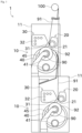
- FIG. 1 is a front view of a yarn winding machine 1 according to an embodiment of the present invention.
- FIG. 2 is a block diagram of the yarn winding machine 1.
- upstream or downstream in a yarn running direction may simply be referred to as “upstream” or “downstream”.
- An unillustrated spinning machine is arranged upstream of the yarn winding machine 1 illustrated in FIG. 1 .
- a yarn 91 produced by the spinning machine is supplied to a yarn winding machine 1 via a yarn feed roller 100.
- the yarn winding machine 1 winds the yarn 91 on a bobbin 90 and forms a yarn layer on the bobbin 90 to produce a package 92.
- the yarn 91 is an elastic yarn such as spandex.
- the type of yarn 91 is not limited to such a yarn, and a synthetic yarn such as nylon or polyester may be used.
- the yarn winding machine 1 includes two winding units 10 arranged vertically.
- the yarn 91 is individually supplied to each of the winding units 10, and the package 92 is individually produced at each of the winding units 10.
- the winding units 10 are supplied with a plurality of the yarns 91 arranged in an axial direction of the package 92.
- the winding units 10 wind each of the plurality of yarns 91 to manufacture the plurality of the packages 92.
- each of the winding units 10 includes a frame 11, a first housing 20, a second housing 30, and a turret plate 40.
- the frame 11 is a member that holds each component provided in the winding unit 10.
- the first housing 20 is attached with a traverse device 21.
- a traverse guide 23 described later reciprocates in a winding width direction (axial direction of the package 92) while being engaged with each yarn 91, the traverse device 21 traverses the yarn 91 fed downstream.
- the traverse device 21 includes a traverse cam 22 and the traverse guide 23.
- the traverse cam 22 is a roller-shaped member arranged parallel to the bobbin 90. A spiral cam groove is formed on an outer peripheral surface of the traverse cam 22.
- the traverse cam 22 is rotationally driven by a traverse motor 51.
- the traverse motor 51 is controlled by a control device 50.
- the control device 50 includes a CPU, a ROM, and a RAM.
- the CPU executes various controls related to the winding unit 10 by reading a program stored in the ROM into the RAM and executing such a program.
- the traverse guide 23 is a portion that engages with the yarn 91 extending from the yarn feed roller 100 to a contact roller 31 described later.
- a distal end of the traverse guide 23 includes, for example, a substantially U-shaped guide part that engages with the yarn 91 while sandwiching the yarn 91 in the winding width direction.
- a proximal end of the traverse guide 23 is positioned in a cam groove of the traverse cam 22.
- the second housing 30 is rotatably attached with a contact roller 31.
- the contact roller 31 is driven to rotate with a contact with the yarn layer of the package 92 with a predetermined pressure to arrange a yarn layer shape of the package 92.
- the traverse device 21 and the contact roller 31 are arranged to face each other with the yarn 91 from the yarn feed roller 100 to the contact roller 31 being interposed therebetween.
- the contact roller 31 is attached to the second housing 30 via an unillustrated arm. With the arm swinging, the contact roller 31 is allowed to move relative to the second housing 30 in a vertical direction. Although the contact roller 31 of this embodiment moves downward by its own weight, the contact roller 31 may be driven downward and upward by an actuator such as a cylinder.
- the winding unit 10 includes a position sensor 52 configured to detect swinging of the arm.
- the position sensor 52 is, for example, a contact sensor, and detects whether the contact roller 31 is within a predetermined distance from the second housing 30. A detection result of the contact roller 31 is output to the control device 50.
- An operation panel 32 is provided on the second housing 30.
- the operation panel 32 is a device operated by an operator.
- the operator applies an instruction to the winding unit 10 by operating the operation panel 32. Examples of the instruction applied by the operator include starting winding, stopping winding, and changing a winding condition.
- the turret plate 40 is a disk-shaped member.
- the turret plate 40 is rotatably attached to the frame 11.
- a rotation axis of the turret plate 40 is at a center position of the turret plate 40.
- the turret plate 40 is rotationally driven by a turret motor 53 illustrated in FIG. 2 .
- the turret motor 53 is controlled by the control device 50.
- bobbin holders 41 are provided, respectively.
- the bobbin holders 41 are attachable with a plurality of bobbins 90 aligned in the axial direction. When the turret plate 40 is rotated, it is possible to change positions of the two bobbin holders 41.
- Each of the bobbin holders 41 is supported by the turret plate 40 in a cantilevered state.
- Each of the bobbin holders 41 can rotate with respect to the turret plate 40 around the position of the axis of the bobbin holder 41 as the center of rotation.
- Each of the two bobbin holders 41 is rotationally driven individually by a bobbin holder motor 54 illustrated in FIG. 2 .
- the bobbin holder motor 54 is controlled by the control device 50.
- the yarn 91 is wound on the upper one of the two bobbin holders 41.
- the yarns are threaded onto the bobbins 90 of one of the bobbin holders 41, and then the other of the bobbin holders 41 contacts the contact roller 31, and the other bobbin holder 41 is rotated in such a state, resulting in winding of the yarns 91 on the bobbins 90 of the other bobbin holder 41 to manufacture the package 92.
- a distal end support member 45 is provided for supporting an end at a free end side of one of the bobbin holders 41 positioned to contact the contact roller 31.
- the turret plate 40 rotates to switch the positions of the two bobbin holders 41. Thereafter, while the package 92 in which the full winding is achieved is collected, the yarn 91 is wound on the bobbin 90 attached to one of the bobbin holders 41.
- the winding unit 10 includes a lifting and lowering device 60.
- the lifting and lowering device 60 lifts and lowers the first housing 20 and the second housing 30 all together.
- the first housing 20 and the second housing 30 are attached to an unillustrated lifting and lowering member.
- a ball nut 61 is attached to the lifting and lowering member.
- a screw rod 62 is attached to the frame 11.
- the lifting motor 63 is controlled by the control device 50. It is noted that the lifting and lowering device 60 may be realized by using a cylinder instead of the ball screw.
- the control device 50 controls the lifting and lowering device 60 according to a thickness of the winding of the package 92 as follows. As described above, the contact roller 31 can move upward and downward with respect to the second housing 30. Therefore, increase in the thickness of the winding of the package 92 as a result of winding the yarn 91 causes upward movement of the contact roller 31 relative to the second housing 30. Based on a detection result from the position sensor 52, the control device 50 determines whether the contact roller 31 is within a predetermined distance from the second housing 30. When the control device 50 determines that the contact roller 31 is within a predetermined distance from the second housing 30, the control device 50 controls the lifting and lowering device 60 to move the first housing 20 and the second housing 30 upward. By repeating such a process, it is possible to move the first housing 20 and the second housing 30 upward according to the thickness of the winding of the package 92.
- each winding unit 10 a yarn path of the yarn 91 supplied to each winding unit 10 will be described.
- one of the winding units 10 arranged on an upper side is referred to as “upper winding unit 10”
- the other one of the winding units 10 arranged on a lower side is referred to as “lower winding unit 10”.
- the upper and lower winding units 10 are offset from each other in a horizontal direction.
- the direction of the offset between the upper winding unit 10 and the lower winding unit 10 coincides with a direction orthogonal to the axial direction of the package 92 in a horizontal plane.
- the yarns 91 are supplied from the single yarn feed roller 100 to the upper winding unit 10 and the lower winding unit 10. Therefore, at least one of the upper and lower winding units 10 cannot be supplied with the yarn 91 along a yarn path parallel to a vertical direction.
- the yarn path of the yarn 91 supplied to the lower winding unit 10 is set parallel to the vertical direction, and the yarn path of the yarn 91 supplied to the upper winding unit 10 is inclined relative to the vertical direction. In other words, an angle of inclination with respect to the vertical direction of the yarn path of the yarn 91 supplied to the upper winding unit 10 is greater than an angle of inclination with respect to the vertical direction of the yarn path of the yarn 91 supplied to the lower winding unit 10.
- the term “parallel” may not only be strictly parallel but also substantially parallel (may also include slightly different angles). The same is true for "vertical”.
- the yarn path may change depending on the progress of winding, the position of the traverse device 21, and the like, but unless otherwise specified, the yarn path indicates the position of the yarn path at the time of a start of winding.
- the upper winding unit 10 preferably has a layout corresponding to an inclined yarn path. For example, if all devices related to the winding the yarn 91 are inclined, the upper winding unit 10 increases in size, hence not preferable. Therefore, in this embodiment, only the first housing 20 of the upper winding unit 10 is arranged to be inclined along the yarn path. As a result, the traverse device 21 is arranged along the yarn path, so that it is possible to appropriately traverse the yarn 91 by using the traverse guide 23. As compared to a configuration where all the devices related to the winding are inclined, it is possible to reduce the size of the yarn winding machine 1.
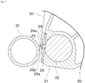
- FIG. 3 illustrates a front sectional view of the traverse device 21 and the vicinity of the traverse device 21.
- the traverse device 21 includes an upstream guide rail 24 and a downstream guide rail 25.
- the upstream guide rail 24 and the downstream guide rail 25 contact the traverse guide 23 and guide movement of the traverse guide 23.
- the upstream guide rail 24 and the downstream guide rail 25 allow movement of the traverse guide 23 in the winding width direction (traverse direction).
- a slide space is formed by the upstream guide rail 24 and the downstream guide rail 25. A part of the traverse guide 23 is located in the slide space. Therefore, the traverse guide 23 can slide in the winding width direction.
- the upstream guide rail 24 is in contact with and interferes with a top surface of the traverse guide 23 to restrict movement of the traverse guide 23 toward an upstream side of the yarn path.
- the downstream guide rail 25 is in contact with and interferes with a bottom surface of the traverse guide 23 to restrict movement of the traverse guide 23 toward a downstream side of the yarn path.
- upstream facing surface 24a a surface facing the yarn path of the upstream guide rail 24
- downstream facing surface 25a A surface facing the yarn path of the downstream guide rail 25
- the traverse device 21 is inclined according to the inclination of the yarn path, and thus, the upstream facing surface 24a is formed to run along the yarn path. More specifically, the upstream facing surface 24a has a two-tiered shape and includes two surfaces at different positions, both of which surfaces are formed along the yarn path.
- the downstream facing surface 25a includes a retraction surface 25b progressively separated from the yarn path toward the downstream of the yarn path. More specifically, the downstream facing surface 25a has a two-tiered shape, and a surface closer to the yarn path is the retraction surface 25b.
- the retraction surface 25b in this embodiment is an inclined surface (flat surface) and may include a curved surface.
- the retraction surface 25b of this embodiment extends along the vertical direction.
- the retraction surface 25b may be on a yarn path side or a traverse cam 22 side with respect to the vertical direction. In most cases, the retraction surface may not be provided on the upstream facing surface 24a.
- a surface symmetrical with the retraction surface 25b (a surface progressively retracting from the yarn path, toward the upstream side of the yarn path) may be provided in the upstream facing surface 24a.
- one tier of the two-tiered downstream facing surface 25a is the retraction surface 25b, but the entire downstream facing surface 25a may be the retraction surface 25b.
- the winding unit 10 of this embodiment has a function of adjusting the shape of the package 92 by performing control to temporarily change a height of the traverse guide 23 with respect to the contact roller 31. It is possible to change the height of the traverse guide 23 with respect to the contact roller 31 by controlling the lifting and lowering device 60 described above, for example. This is because if the first housing 20 and the second housing 30 are lifted by the lifting and lowering device 60, the height of the traverse guide 23 increases while the height of the contact roller 31 does not change due to its own weight.
- Yarn threading refers to threading (fixing) the yarn 91 on the bobbin 90 of one of the bobbin holders 41 before the yarn 91 is wound by the yarn winding machine 1.
- an operator uses a suction gun or the like to catch the yarn 91 and winds the yarn 91 around the bobbin 90 a plurality of times to perform the yarn threading.
- the yarn winding machine 1 may perform the yarn threading.
- the operator operates, for example, the operation panel 32 to perform input of performing the yarn threading.
- the control device 50 controls the turret motor 53 to rotate the turret plate 40.
- the bobbin holder 41 reaches a yarn threading position.
- the yarn threading position of the bobbin holder 41 of this embodiment is on a traverse guide side, with respect to the contact roller 31. Thereafter, yarn threading is performed by the operator.
- the yarn threading position of the bobbin holder 41 is on the traverse guide side with respect to the contact roller 31, the yarn path is shifted to the traverse guide side.
- the yarn 91 comes close to the downstream guide rail 25. Therefore, if the downstream guide rail 25 has a conventional shape, the yarn 91 may possibly come into contact with the downstream guide rail 25.
- the downstream guide rail 25 of this embodiment is formed with the retraction surface 25b, and thus, the yarn 91 is less likely to contact the downstream guide rail 25.
- the downstream guide rail 25 has the conventional shape, to prevent the yarn 91 from contacting the downstream guide rail 25, it is necessary that the bobbin holder 41 is arranged at a yarn threading position such that the yarn path is shifted to the contact roller 31 side. However, if such a yarn threading position of the bobbin holder 41 is selected, the yarn 91 may possibly come into contact with the contact roller 31, resulting in an error in the yarn threading operation. Moreover, if the distal end support member 45 is provided as in this embodiment, it is difficult to execute the yarn threading operation. Thus, when the downstream guide rail 25 is formed with the retraction surface 25b, it is possible to select the yarn threading position of the bobbin holders 41 such that the error in the yarn threading operation hardly occurs and the yarn threading operation is easily performed.
- the yarn winding machine 1 of this embodiment includes the bobbin holder 41, the contact roller 31, and the traverse device 21.
- the bobbin holder 41 holds the bobbin 90.
- the contact roller 31 rotates in contact with the package 92.
- the traverse device 21 faces the contact roller 31 and is arranged to sandwich the yarn 91 extending from the yarn feed roller 100 to the contact roller 31, between the traverse device 21 and the contact roller 31.
- the traverse device 21 includes the traverse guide 23, the upstream guide rail 24, and the downstream guide rail 25.
- the traverse guide 23 contacts the yarn 91 extending from the yarn feed roller 100 to the contact roller 31 to traverse the yarn 91.
- the upstream guide rail 24 allows movement of the traverse guide 23 in a winding width direction and restricts movement of the traverse guide 23 toward an upstream side of a yarn path.
- the downstream guide rail 25 allows movement of the traverse guide 23 in the winding width direction and restricts movement of the traverse guide 23 toward a downstream side of the yarn path.
- the yarn path from the yarn feed roller 100 to the contact roller 31 is inclined with respect to a vertical direction.
- the downstream guide rail 25 has the downstream facing surface 25a facing the yarn path, and the downstream facing surface 25a includes the retraction surface 25b progressively separated from the yarn path toward the downstream of the yarn path, as viewed in an axial direction of the package 92.
- the bobbin holder 41 on which the yarn 91 is threaded can be located at a position closer to the traverse device 21 side, with respect to the contact roller 31, and thus the yarn 91 extending from the yarn feed roller 100 to the bobbin holder 41 can be spaced apart from the contact roller 31. Therefore, the risk of yarn breakage during the yarn threading operation due to contact between the yarn 91 and the contact roller 31 is reduced. As a result, it is possible to secure the degree of freedom in positioning the bobbin holder 41 during the yarn threading operation.
- the upstream facing surface 24a is formed along the yarn path, as viewed in the axial direction of the package 92.
- the yarn winding machine 1 of this embodiment includes a plurality of winding units 10 each including the bobbin holder 41, the contact roller 31, and the traverse device 21.
- the winding units 10 are arranged vertically or horizontally.
- the winding units 10 are arranged vertically.
- An angle of inclination with respect to the vertical direction of the yarn path from the yarn feed roller 100 to the contact roller 31 arranged on an upper side is larger than an angle of inclination with respect to the vertical direction of the yarn path from the yarn feed roller 100 to the contact roller 31 arranged on a lower side.
- the downstream facing surface 25a of the downstream guide rail 25 includes the retraction surface 25b.
- the yarn winding machine 1 of this embodiment includes the lifting and lowering device 60 that moves the traverse guide 23 relative to the contact roller 31 in the height direction, which is a direction in which the yarn feed roller 100 is positioned with respect to the yarn winding machine 1.
- a yarn threading position at which the yarn 91 is threaded to the bobbin 90 is on the traverse guide 23 side, with respect to the contact roller 31.
- the yarn path is close to the downstream guide rail 25 during yarn threading.
- the retraction surface 25b is formed in the downstream guide rail 25.
- the winding units 10 are arranged vertically. Alternatively, the winding units 10 may be arranged horizontally. Also in this case, the yarn path of the yarn 91 supplied from the yarn feed roller 100 to at least one of the winding units 10 is inclined with respect to the vertical direction, and thus, the present invention is applicable.
- the present invention is applicable to any yarn winding machine in which the yarn path of the yarn 91 supplied from the yarn feed roller 100 is inclined with respect to the vertical direction.
- the traverse device 21 of the above embodiment is of cam drum type, the traverse device 21 may have a different configuration as long as it is possible to reciprocate the traverse guide 23 in the winding width direction.
- a belt-type traverse device instead of the traverse device 21, may be used.
- the upstream facing surface 24a and the downstream facing surface 25a of the lower winding unit 10 may be formed along the yarn path.
Landscapes
- Guides For Winding Or Rewinding, Or Guides For Filamentary Materials (AREA)
- Winding Filamentary Materials (AREA)
Abstract
Description
- The present invention mainly relates to a yarn winding machine for winding a yarn on a bobbin to produce a package.
-
Patent Literature 1 isJapanese Utility Model Registration No. 3209831 - In
Patent Literature 1, two winding devices are arranged for one godet roller (yarn feed roller). Therefore, a yarn path extending from the godet roller to the winding device is inclined with respect to a vertical direction.Patent Literature 1 discloses a layout in which a traverse yarn guide device is inclined in accordance with an inclination of the yarn path. - In the winding device of
Patent Literature 1, the traverse yarn guide device is inclined, and thus, the traverse yarn guide device protrudes greatly in a horizontal direction as the traverse yarn guide device approaches vertically downward. Therefore, in the layout ofPatent Literature 1, due to the inclination of the traverse yarn guide device, during a yarn threading operation of firstly thread a yarn to a bobbin holder of the winding device, depending on a position of the bobbin holder to which the yarn is threaded, the yarn may contact the traverse yarn guide device and as a result, yarn breakage may occur. Thus, in the layout ofPatent Literature 1, the degree of freedom in positioning the bobbin holder during the yarn threading operation is decreased. - The present invention has been made in view of the above circumstances, and a primary object of the present invention is to provide, for a yarn winding machine in which a yarn path of a yarn fed from a yarn feed roller is inclined with respect to a vertical direction, a configuration that can secure a degree of freedom in a position of a bobbin holder during yarn threading operation.
- Problems to be solved by the present invention are as described above, and next, means for solving the problems and effects thereof will be described.
- According to an aspect of the present invention, a yarn winding machine with the following configuration is provided. That is, the yarn winding machine winds a yarn fed from a yarn feed roller on a bobbin to produce a package. The yarn winding machine includes a bobbin holder, a contact roller, and a traverse device. The bobbin holder holds the bobbin. The contact roller rotates in contact with the package. The traverse device is arranged to face the contact roller and to sandwich, together with the contact roller, the yarn extending from the yarn feed roller to the contact roller. The traverse device includes a traverse guide, an upstream guide rail, and a downstream guide rail. The traverse guide contacts the yarn extending from the yarn feed roller to the contact roller to traverse the yarn. The upstream guide rail allows movement of the traverse guide in a winding width direction and restricts movement of the traverse guide toward an upstream side of a yarn path. The downstream guide rail allows movement of the traverse guide in the winding width direction and restricts movement of the traverse guide toward a downstream side of the yarn path. During winding of the yarn, the yarn path from the yarn feed roller to the contact roller is inclined with respect to a vertical direction. The downstream guide rail has a downstream facing surface facing the yarn path, and the downstream facing surface includes a retraction surface progressively separated from the yarn path toward the downstream of the yarn path, as viewed in an axial direction of the package.
- When the retraction surface is formed in the downstream guide rail, during the yarn threading operation, the bobbin holder on which the yarn is threaded can be located at a position closer to the traverse device side, with respect to the contact roller, and thus the yarn extending from the yarn feed roller to the bobbin holder can be spaced apart from the contact roller. Therefore, the risk of yarn breakage during the yarn threading operation due to contact between the yarn and the contact roller is reduced. As a result, it is possible to secure the degree of freedom in positioning the bobbin holder during the yarn threading operation.
- In the yarn winding machine, it is preferable that in an upstream facing surface is formed along the yarn path, as viewed in the axial direction of the package.
- When the retraction surface is formed only on the downstream guide rail having a high probability of coming into contact with the yarn, it is possible to simplify a shape of the upstream guide rail.
- The yarn winding machine preferably has the following configuration. That is, the yarn winding machine includes a plurality of winding units each including the bobbin holder, the contact roller, and the traverse device. The winding units are arranged vertically or horizontally.
- When the winding units are arranged vertically or horizontally and the yarns are supplied from a single yarn feed roller, a yarn path from the yarn feed roller to the contact roller needs to be inclined. Thus, it is possible to effectively utilize the configuration where the retraction surface is formed in the downstream guide rail.
- The yarn winding machine preferably has the following configuration. That is, the winding units are arranged vertically. An angle of inclination with respect to the vertical direction of the yarn path from the yarn feed roller to the contact roller arranged on an upper side is larger than an angle of inclination with respect to the vertical direction of the yarn path from the yarn feed roller to the contact roller arranged on a lower side. At least in the winding unit arranged on the upper side, the downstream facing surface of the downstream guide rail includes the retraction surface.
- As a result, it is possible to provide the retraction surface in the downstream guide rail of the winding unit for which an inclined yarn path is set.
- It is preferable that the yarn winding machine includes a lifting and lowering device that moves the traverse guide relative to the contact roller in a height direction, which is a direction in which the yarn feed roller is positioned with respect to the yarn winding machine.
- When the height of the traverse guide relative to the contact roller changes, the angle of inclination of the yarn path with respect to the vertical direction changes. Thus, it is possible to effectively utilize the configuration where the retraction surface is formed in the downstream guide rail.
- In the yarn winding machine, as viewed in an axial direction of the package, it is preferable that a yarn threading position at which the yarn is threaded to the bobbin is on the traverse guide side, with respect to the contact roller.
- When the yarn threading position is on the traverse guide side, the yarn path is close to the downstream guide rail during yarn threading. Thus, it is possible to effectively utilize the configuration where the retraction surface is formed in the downstream guide rail.
-
-
FIG. 1 is a front view of a yarn winding machine according to an embodiment of the present invention; -
FIG. 2 is a block diagram of the yarn winding machine; -
FIG. 3 is a front sectional view of a traverse device and the vicinity of the traverse device; -
FIG. 4 is a diagram for explaining that a traverse width is shortened depending on a difference in free length; and -
FIG. 5 is a front view of an upper winding unit during yarn threading. - Next, an embodiment of the present invention will be described with reference to drawings.
FIG. 1 is a front view of ayarn winding machine 1 according to an embodiment of the present invention.FIG. 2 is a block diagram of theyarn winding machine 1. In the following description, upstream or downstream in a yarn running direction may simply be referred to as "upstream" or "downstream". - An unillustrated spinning machine is arranged upstream of the
yarn winding machine 1 illustrated inFIG. 1 . Ayarn 91 produced by the spinning machine is supplied to ayarn winding machine 1 via ayarn feed roller 100. Theyarn winding machine 1 winds theyarn 91 on abobbin 90 and forms a yarn layer on thebobbin 90 to produce apackage 92. Theyarn 91 is an elastic yarn such as spandex. However, the type ofyarn 91 is not limited to such a yarn, and a synthetic yarn such as nylon or polyester may be used. - As illustrated in
FIG. 1 , theyarn winding machine 1 includes twowinding units 10 arranged vertically. Theyarn 91 is individually supplied to each of thewinding units 10, and thepackage 92 is individually produced at each of thewinding units 10. Thewinding units 10 are supplied with a plurality of theyarns 91 arranged in an axial direction of thepackage 92. The windingunits 10 wind each of the plurality ofyarns 91 to manufacture the plurality of thepackages 92. - The two winding
units 10 each include the same device, and thus, the upper and lower windingunits 10 will be collectively described below. As illustrated inFIG. 1 , each of the windingunits 10 includes aframe 11, afirst housing 20, asecond housing 30, and aturret plate 40. - The
frame 11 is a member that holds each component provided in the windingunit 10. Thefirst housing 20 is attached with atraverse device 21. When atraverse guide 23 described later reciprocates in a winding width direction (axial direction of the package 92) while being engaged with eachyarn 91, thetraverse device 21 traverses theyarn 91 fed downstream. As illustrated inFIG. 2 , thetraverse device 21 includes atraverse cam 22 and thetraverse guide 23. - The
traverse cam 22 is a roller-shaped member arranged parallel to thebobbin 90. A spiral cam groove is formed on an outer peripheral surface of thetraverse cam 22. Thetraverse cam 22 is rotationally driven by atraverse motor 51. - The
traverse motor 51 is controlled by acontrol device 50. Thecontrol device 50 includes a CPU, a ROM, and a RAM. The CPU executes various controls related to the windingunit 10 by reading a program stored in the ROM into the RAM and executing such a program. - The
traverse guide 23 is a portion that engages with theyarn 91 extending from theyarn feed roller 100 to acontact roller 31 described later. A distal end of thetraverse guide 23 includes, for example, a substantially U-shaped guide part that engages with theyarn 91 while sandwiching theyarn 91 in the winding width direction. A proximal end of thetraverse guide 23 is positioned in a cam groove of thetraverse cam 22. With such a configuration, when thetraverse cam 22 is rotationally driven, it is possible to reciprocate thetraverse guide 23 in the winding width direction. - The
second housing 30 is rotatably attached with acontact roller 31. When theyarn 91 is wound, thecontact roller 31 is driven to rotate with a contact with the yarn layer of thepackage 92 with a predetermined pressure to arrange a yarn layer shape of thepackage 92. Thetraverse device 21 and thecontact roller 31 are arranged to face each other with theyarn 91 from theyarn feed roller 100 to thecontact roller 31 being interposed therebetween. - The
contact roller 31 is attached to thesecond housing 30 via an unillustrated arm. With the arm swinging, thecontact roller 31 is allowed to move relative to thesecond housing 30 in a vertical direction. Although thecontact roller 31 of this embodiment moves downward by its own weight, thecontact roller 31 may be driven downward and upward by an actuator such as a cylinder. - As illustrated in
FIG. 2 , the windingunit 10 includes aposition sensor 52 configured to detect swinging of the arm. Theposition sensor 52 is, for example, a contact sensor, and detects whether thecontact roller 31 is within a predetermined distance from thesecond housing 30. A detection result of thecontact roller 31 is output to thecontrol device 50. - An
operation panel 32 is provided on thesecond housing 30. Theoperation panel 32 is a device operated by an operator. The operator applies an instruction to the windingunit 10 by operating theoperation panel 32. Examples of the instruction applied by the operator include starting winding, stopping winding, and changing a winding condition. - The
turret plate 40 is a disk-shaped member. Theturret plate 40 is rotatably attached to theframe 11. A rotation axis of theturret plate 40 is at a center position of theturret plate 40. Theturret plate 40 is rotationally driven by aturret motor 53 illustrated inFIG. 2 . Theturret motor 53 is controlled by thecontrol device 50. - At two locations facing each other across the center position, within the
turret plate 40,bobbin holders 41 are provided, respectively. Thebobbin holders 41 are attachable with a plurality ofbobbins 90 aligned in the axial direction. When theturret plate 40 is rotated, it is possible to change positions of the twobobbin holders 41. Each of thebobbin holders 41 is supported by theturret plate 40 in a cantilevered state. - Each of the
bobbin holders 41 can rotate with respect to theturret plate 40 around the position of the axis of thebobbin holder 41 as the center of rotation. Each of the twobobbin holders 41 is rotationally driven individually by abobbin holder motor 54 illustrated inFIG. 2 . Thebobbin holder motor 54 is controlled by thecontrol device 50. - With the two
bobbin holders 41 arranged vertically, theyarn 91 is wound on the upper one of the twobobbin holders 41. Specifically, the yarns are threaded onto thebobbins 90 of one of thebobbin holders 41, and then the other of thebobbin holders 41 contacts thecontact roller 31, and theother bobbin holder 41 is rotated in such a state, resulting in winding of theyarns 91 on thebobbins 90 of theother bobbin holder 41 to manufacture thepackage 92. It is noted that a distalend support member 45 is provided for supporting an end at a free end side of one of thebobbin holders 41 positioned to contact thecontact roller 31. - Once a predetermined amount of
yarn 91 has been wound and full winding of thepackage 92 has been achieved, theturret plate 40 rotates to switch the positions of the twobobbin holders 41. Thereafter, while thepackage 92 in which the full winding is achieved is collected, theyarn 91 is wound on thebobbin 90 attached to one of thebobbin holders 41. - As illustrated in
FIG. 2 , the windingunit 10 includes a lifting and loweringdevice 60. The lifting and loweringdevice 60 lifts and lowers thefirst housing 20 and thesecond housing 30 all together. Specifically, thefirst housing 20 and thesecond housing 30 are attached to an unillustrated lifting and lowering member. Aball nut 61 is attached to the lifting and lowering member. Ascrew rod 62 is attached to theframe 11. When thescrew rod 62 is rotated by using a liftingmotor 63, it is possible to lift and lower thefirst housing 20 and thesecond housing 30. The liftingmotor 63 is controlled by thecontrol device 50. It is noted that the lifting and loweringdevice 60 may be realized by using a cylinder instead of the ball screw. - The
control device 50 controls the lifting and loweringdevice 60 according to a thickness of the winding of thepackage 92 as follows. As described above, thecontact roller 31 can move upward and downward with respect to thesecond housing 30. Therefore, increase in the thickness of the winding of thepackage 92 as a result of winding theyarn 91 causes upward movement of thecontact roller 31 relative to thesecond housing 30. Based on a detection result from theposition sensor 52, thecontrol device 50 determines whether thecontact roller 31 is within a predetermined distance from thesecond housing 30. When thecontrol device 50 determines that thecontact roller 31 is within a predetermined distance from thesecond housing 30, thecontrol device 50 controls the lifting and loweringdevice 60 to move thefirst housing 20 and thesecond housing 30 upward. By repeating such a process, it is possible to move thefirst housing 20 and thesecond housing 30 upward according to the thickness of the winding of thepackage 92. - Next, a yarn path of the
yarn 91 supplied to each windingunit 10 will be described. In the following description, one of the windingunits 10 arranged on an upper side is referred to as "upper windingunit 10", and the other one of the windingunits 10 arranged on a lower side is referred to as "lower windingunit 10". - In this embodiment, in order that the
yarn 91 supplied to the lower windingunit 10 does not interfere with the upper windingunit 10, the upper and lower windingunits 10 are offset from each other in a horizontal direction. The direction of the offset between the upper windingunit 10 and the lower windingunit 10 coincides with a direction orthogonal to the axial direction of thepackage 92 in a horizontal plane. - As described above, in this embodiment, the
yarns 91 are supplied from the singleyarn feed roller 100 to the upper windingunit 10 and the lower windingunit 10. Therefore, at least one of the upper and lower windingunits 10 cannot be supplied with theyarn 91 along a yarn path parallel to a vertical direction. Specifically, the yarn path of theyarn 91 supplied to the lower windingunit 10 is set parallel to the vertical direction, and the yarn path of theyarn 91 supplied to the upper windingunit 10 is inclined relative to the vertical direction. In other words, an angle of inclination with respect to the vertical direction of the yarn path of theyarn 91 supplied to the upper windingunit 10 is greater than an angle of inclination with respect to the vertical direction of the yarn path of theyarn 91 supplied to the lower windingunit 10. - In this embodiment, the term "parallel" may not only be strictly parallel but also substantially parallel (may also include slightly different angles). The same is true for "vertical". The yarn path may change depending on the progress of winding, the position of the
traverse device 21, and the like, but unless otherwise specified, the yarn path indicates the position of the yarn path at the time of a start of winding. - The upper winding
unit 10 preferably has a layout corresponding to an inclined yarn path. For example, if all devices related to the winding theyarn 91 are inclined, the upper windingunit 10 increases in size, hence not preferable. Therefore, in this embodiment, only thefirst housing 20 of the upper windingunit 10 is arranged to be inclined along the yarn path. As a result, thetraverse device 21 is arranged along the yarn path, so that it is possible to appropriately traverse theyarn 91 by using thetraverse guide 23. As compared to a configuration where all the devices related to the winding are inclined, it is possible to reduce the size of theyarn winding machine 1. - Next, the influence caused by inclining the
traverse device 21 will be described with reference toFIG. 3. FIG. 3 illustrates a front sectional view of thetraverse device 21 and the vicinity of thetraverse device 21. - As illustrated in
FIG. 3 , thetraverse device 21 includes anupstream guide rail 24 and adownstream guide rail 25. Theupstream guide rail 24 and thedownstream guide rail 25 contact thetraverse guide 23 and guide movement of thetraverse guide 23. Theupstream guide rail 24 and thedownstream guide rail 25 allow movement of thetraverse guide 23 in the winding width direction (traverse direction). Specifically, a slide space is formed by theupstream guide rail 24 and thedownstream guide rail 25. A part of thetraverse guide 23 is located in the slide space. Therefore, thetraverse guide 23 can slide in the winding width direction. - The
upstream guide rail 24 is in contact with and interferes with a top surface of thetraverse guide 23 to restrict movement of thetraverse guide 23 toward an upstream side of the yarn path. Thedownstream guide rail 25 is in contact with and interferes with a bottom surface of thetraverse guide 23 to restrict movement of thetraverse guide 23 toward a downstream side of the yarn path. Such a configuration allows thetraverse guide 23 to move only in the winding width direction without moving in a direction along the yarn path. - Here, a surface facing the yarn path of the
upstream guide rail 24 is referred to as "upstream facingsurface 24a". A surface facing the yarn path of thedownstream guide rail 25 is referred to as "downstream facingsurface 25a". In this embodiment, thetraverse device 21 is inclined according to the inclination of the yarn path, and thus, the upstream facingsurface 24a is formed to run along the yarn path. More specifically, the upstream facingsurface 24a has a two-tiered shape and includes two surfaces at different positions, both of which surfaces are formed along the yarn path. - In contrast, the downstream facing
surface 25a according to this embodiment includes aretraction surface 25b progressively separated from the yarn path toward the downstream of the yarn path. More specifically, the downstream facingsurface 25a has a two-tiered shape, and a surface closer to the yarn path is theretraction surface 25b. - It is noted that the
retraction surface 25b in this embodiment is an inclined surface (flat surface) and may include a curved surface. Theretraction surface 25b of this embodiment extends along the vertical direction. However, depending on the yarn path of theyarn winding machine 1, theretraction surface 25b may be on a yarn path side or atraverse cam 22 side with respect to the vertical direction. In most cases, the retraction surface may not be provided on the upstream facingsurface 24a. However, for reasons of the symmetry of components, for example, a surface symmetrical with theretraction surface 25b (a surface progressively retracting from the yarn path, toward the upstream side of the yarn path) may be provided in the upstream facingsurface 24a. In this embodiment, one tier of the two-tiereddownstream facing surface 25a is theretraction surface 25b, but the entire downstream facingsurface 25a may be theretraction surface 25b. - The winding
unit 10 of this embodiment has a function of adjusting the shape of thepackage 92 by performing control to temporarily change a height of thetraverse guide 23 with respect to thecontact roller 31. It is possible to change the height of thetraverse guide 23 with respect to thecontact roller 31 by controlling the lifting and loweringdevice 60 described above, for example. This is because if thefirst housing 20 and thesecond housing 30 are lifted by the lifting and loweringdevice 60, the height of thetraverse guide 23 increases while the height of thecontact roller 31 does not change due to its own weight. - As illustrated in
FIG. 4 , if the height of thetraverse guide 23 with respect to thecontact roller 31 is increased, a free length of theyarn 91 is increased (from FL1 to FL2 inFIG. 4 ). This lengthens a traverse delay (from D1 to D2 inFIG. 4 ) and shortens a traverse width. Therefore, when the height of thetraverse guide 23 with respect to thecontact roller 31 is temporarily increased, it is possible to suppress an increase in thickness of the yarn layer at ends in the winding width direction (a high edge) of thepackage 92. - Changing the height of the
traverse guide 23 with respect to thecontact roller 31 causes a change of the yarn path. Thus, if theretraction surface 25b is not provided, theyarn 91 and thedownstream guide rail 25 may come into contact with each other. However, thedownstream guide rail 25 of this embodiment is provided with theretraction surface 25b, and thus, during such a control, it is possible to suppress the contact between theyarn 91 and thedownstream guide rail 25. - Next, with reference to
FIG. 5 , the position of thebobbin 90 during yarn threading will be described. Yarn threading refers to threading (fixing) theyarn 91 on thebobbin 90 of one of thebobbin holders 41 before theyarn 91 is wound by theyarn winding machine 1. In this embodiment, an operator uses a suction gun or the like to catch theyarn 91 and winds theyarn 91 around the bobbin 90 a plurality of times to perform the yarn threading. It is noted that instead of the operator, theyarn winding machine 1 may perform the yarn threading. - The operator operates, for example, the
operation panel 32 to perform input of performing the yarn threading. In response to the input by the operator, thecontrol device 50 controls theturret motor 53 to rotate theturret plate 40. As a result, thebobbin holder 41 reaches a yarn threading position. As illustrated inFIG. 5 , the yarn threading position of thebobbin holder 41 of this embodiment is on a traverse guide side, with respect to thecontact roller 31. Thereafter, yarn threading is performed by the operator. - Here, if the yarn threading position of the
bobbin holder 41 is on the traverse guide side with respect to thecontact roller 31, the yarn path is shifted to the traverse guide side. Thus, theyarn 91 comes close to thedownstream guide rail 25. Therefore, if thedownstream guide rail 25 has a conventional shape, theyarn 91 may possibly come into contact with thedownstream guide rail 25. However, thedownstream guide rail 25 of this embodiment is formed with theretraction surface 25b, and thus, theyarn 91 is less likely to contact thedownstream guide rail 25. In contrast, if thedownstream guide rail 25 has the conventional shape, to prevent theyarn 91 from contacting thedownstream guide rail 25, it is necessary that thebobbin holder 41 is arranged at a yarn threading position such that the yarn path is shifted to thecontact roller 31 side. However, if such a yarn threading position of thebobbin holder 41 is selected, theyarn 91 may possibly come into contact with thecontact roller 31, resulting in an error in the yarn threading operation. Moreover, if the distalend support member 45 is provided as in this embodiment, it is difficult to execute the yarn threading operation. Thus, when thedownstream guide rail 25 is formed with theretraction surface 25b, it is possible to select the yarn threading position of thebobbin holders 41 such that the error in the yarn threading operation hardly occurs and the yarn threading operation is easily performed. - As described above, the
yarn winding machine 1 of this embodiment includes thebobbin holder 41, thecontact roller 31, and thetraverse device 21. Thebobbin holder 41 holds thebobbin 90. Thecontact roller 31 rotates in contact with thepackage 92. Thetraverse device 21 faces thecontact roller 31 and is arranged to sandwich theyarn 91 extending from theyarn feed roller 100 to thecontact roller 31, between thetraverse device 21 and thecontact roller 31. Thetraverse device 21 includes thetraverse guide 23, theupstream guide rail 24, and thedownstream guide rail 25. Thetraverse guide 23 contacts theyarn 91 extending from theyarn feed roller 100 to thecontact roller 31 to traverse theyarn 91. Theupstream guide rail 24 allows movement of thetraverse guide 23 in a winding width direction and restricts movement of thetraverse guide 23 toward an upstream side of a yarn path. Thedownstream guide rail 25 allows movement of thetraverse guide 23 in the winding width direction and restricts movement of thetraverse guide 23 toward a downstream side of the yarn path. During winding of theyarn 91, the yarn path from theyarn feed roller 100 to thecontact roller 31 is inclined with respect to a vertical direction. Thedownstream guide rail 25 has the downstream facingsurface 25a facing the yarn path, and the downstream facingsurface 25a includes theretraction surface 25b progressively separated from the yarn path toward the downstream of the yarn path, as viewed in an axial direction of thepackage 92. - When the
retraction surface 25b is formed in thedownstream guide rail 25, during the yarn threading operation, thebobbin holder 41 on which theyarn 91 is threaded can be located at a position closer to thetraverse device 21 side, with respect to thecontact roller 31, and thus theyarn 91 extending from theyarn feed roller 100 to thebobbin holder 41 can be spaced apart from thecontact roller 31. Therefore, the risk of yarn breakage during the yarn threading operation due to contact between theyarn 91 and thecontact roller 31 is reduced. As a result, it is possible to secure the degree of freedom in positioning thebobbin holder 41 during the yarn threading operation. - In the
yarn winding machine 1 of this embodiment, the upstream facingsurface 24a is formed along the yarn path, as viewed in the axial direction of thepackage 92. - When the
retraction surface 25b is formed only on thedownstream guide rail 25 having a high probability of coming into contact with theyarn 91, it is possible to simplify a shape of theupstream guide rail 24. - The
yarn winding machine 1 of this embodiment includes a plurality of windingunits 10 each including thebobbin holder 41, thecontact roller 31, and thetraverse device 21. The windingunits 10 are arranged vertically or horizontally. - When the winding
units 10 are arranged vertically or horizontally and theyarns 91 are supplied from a singleyarn feed roller 100, a yarn path from theyarn feed roller 100 to thecontact roller 31 needs to be inclined. Thus, it is possible to effectively utilize the configuration where theretraction surface 25b is formed in thedownstream guide rail 25. - In the
yarn winding machine 1 of this embodiment, the windingunits 10 are arranged vertically. An angle of inclination with respect to the vertical direction of the yarn path from theyarn feed roller 100 to thecontact roller 31 arranged on an upper side is larger than an angle of inclination with respect to the vertical direction of the yarn path from theyarn feed roller 100 to thecontact roller 31 arranged on a lower side. At least in the windingunit 10 arranged on the upper side, the downstream facingsurface 25a of thedownstream guide rail 25 includes theretraction surface 25b. - As a result, it is possible to provide the
retraction surface 25b in thedownstream guide rail 25 of the windingunit 10 for which an inclined yarn path is set. - The
yarn winding machine 1 of this embodiment includes the lifting and loweringdevice 60 that moves thetraverse guide 23 relative to thecontact roller 31 in the height direction, which is a direction in which theyarn feed roller 100 is positioned with respect to theyarn winding machine 1. - When the height of the
traverse guide 23 relative to thecontact roller 31 changes, the angle of inclination of the yarn path with respect to the vertical direction changes. Thus, it is possible to effectively utilize the configuration where theretraction surface 25b is formed in thedownstream guide rail 25. - In the
yarn winding machine 1 of this embodiment, as viewed in the axial direction of thepackage 92, a yarn threading position at which theyarn 91 is threaded to thebobbin 90 is on thetraverse guide 23 side, with respect to thecontact roller 31. - When the yarn threading position is on the traverse guide side, the yarn path is close to the
downstream guide rail 25 during yarn threading. Thus, it is possible to effectively utilize the configuration where theretraction surface 25b is formed in thedownstream guide rail 25. - Although a preferred embodiment of the present invention has been described above, the above-described configuration can be modified, for example, as follows.
- In the
yarn winding machine 1 according to the above embodiment, the windingunits 10 are arranged vertically. Alternatively, the windingunits 10 may be arranged horizontally. Also in this case, the yarn path of theyarn 91 supplied from theyarn feed roller 100 to at least one of the windingunits 10 is inclined with respect to the vertical direction, and thus, the present invention is applicable. The present invention is applicable to any yarn winding machine in which the yarn path of theyarn 91 supplied from theyarn feed roller 100 is inclined with respect to the vertical direction. - Although the
traverse device 21 of the above embodiment is of cam drum type, thetraverse device 21 may have a different configuration as long as it is possible to reciprocate thetraverse guide 23 in the winding width direction. For example, instead of thetraverse device 21, a belt-type traverse device may be used. - In the
traverse device 21 of the above embodiment, the upstream facingsurface 24a and the downstream facingsurface 25a of the lower windingunit 10 may be formed along the yarn path.
Claims (6)
- A yarn winding machine (1) for producing a package (92) by winding a yarn (91) fed from a yarn feed roller (100) on a bobbin (90), the yarn winding machine (1) comprising:a bobbin holder (41) configured to hold the bobbin (90);a contact roller (31) configured to rotate in contact with the package (92); anda traverse device (21) arranged to face the contact roller (31) and to sandwich, together with the contact roller (31), the yarn (91) extending from the yarn feed roller (100) to the contact roller (31), whereinthe traverse device (21) comprises,a traverse guide (23) configured to contact the yarn (91) extending from the yarn feed roller (100) to the contact roller (31) to traverse the yarn (91),an upstream guide rail (24) configured to allow movement of the traverse guide (23) in a winding width direction and restrict movement of the traverse guide (23) toward an upstream side of a yarn path, anda downstream guide rail (25) configured to allow movement of the traverse guide (23) in the winding width direction and restrict movement of the traverse guide (23) toward a downstream side of the yarn path,during winding of the yarn (91), the yarn path from the yarn feed roller (100) to the contact roller (31) is inclined with respect to a vertical direction, andthe downstream guide rail (25) has a downstream facing surface facing the yarn path, and the downstream facing surface includes a retraction surface progressively separated from the yarn path toward the downstream of the yarn path, as viewed in an axial direction of the package (92).
- The yarn winding machine (1) according to claim 1, wherein
the upstream guide rail (24) has an upstream facing surface facing the yarn path, and the upstream facing surface is formed along the yarn path, as viewed in the axial direction of the package (92). - The yarn winding machine (1) according to claim 1 or 2, further comprising a plurality of winding units (10) each including the bobbin holder (41), the contact roller (31), and the traverse device (21), wherein
the plurality of winding units (10) are arranged vertically or horizontally. - The yarn winding machine (1) according to claim 3, whereinthe plurality of winding units (10) are arranged vertically,an angle of inclination with respect to the vertical direction of the yarn path from the yarn feed roller (100) to the contact roller (31) arranged on an upper side is larger than an angle of inclination with respect to the vertical direction of the yarn path from the yarn feed roller (100) to the contact roller (31) arranged on a lower side, andat least in the winding unit (10) arranged on the upper side, the downstream facing surface of the downstream guide rail (25) includes the retraction surface.
- The yarn winding machine (1) according to any one of claims 1 to 4, whereinwhen a direction in which the yarn feed roller (100) is positioned with respect to the yarn winding machine (1) is a height direction,the yarn winding machine (1) includes a lifting and lowering device (60) configured to move the traverse guide (23) relative to the contact roller (31) in the height direction.
- The yarn winding machine (1) according to any one of claims 1 to 5, wherein
as viewed in the axial direction of the package (92),a yarn threading position at which the yarn is threaded to the bobbin (90) is on the traverse guide (23) side, with respect to the contact roller (31).
Applications Claiming Priority (1)
| Application Number | Priority Date | Filing Date | Title |
|---|---|---|---|
| JP2022041181A JP7879709B2 (en) | 2022-03-16 | 2022-03-16 | thread winding machine |
Publications (1)
| Publication Number | Publication Date |
|---|---|
| EP4245705A1 true EP4245705A1 (en) | 2023-09-20 |
Family
ID=85283827
Family Applications (1)
| Application Number | Title | Priority Date | Filing Date |
|---|---|---|---|
| EP23157355.1A Pending EP4245705A1 (en) | 2022-03-16 | 2023-02-17 | Yarn winding machine |
Country Status (4)
| Country | Link |
|---|---|
| EP (1) | EP4245705A1 (en) |
| JP (1) | JP7879709B2 (en) |
| KR (1) | KR20230135504A (en) |
| CN (1) | CN116767942A (en) |
Citations (6)
| Publication number | Priority date | Publication date | Assignee | Title |
|---|---|---|---|---|
| US3933321A (en) * | 1974-02-27 | 1976-01-20 | Kabushiki Kaisha Toyoda Jidoshokki Seisakusho | Device for simultaneously traversing thread guides of a winding apparatus for taking-up plural threads |
| EP1028908B1 (en) * | 1997-10-06 | 2002-07-24 | E.I. Du Pont De Nemours And Company | Winder for synthetic filaments |
| JP2009102162A (en) * | 2007-10-23 | 2009-05-14 | Iljin A Tech Co Ltd | Yarn winding device having double deck |
| EP2145849B1 (en) * | 2008-07-18 | 2012-08-01 | TMT Machinery, Inc. | Yarn winder |
| JP3209831U (en) | 2014-04-22 | 2017-04-13 | 鄭州中遠スパンデックス工程技術有限公司Zhengzhou Zhongyuan Spandex Engineering Technology Co.,Ltd | Winding device and spinning area |
| CN208814380U (en) * | 2017-07-17 | 2019-05-03 | 上海金纬化纤机械制造有限公司 | A kind of yarn winder traversing gear |
Family Cites Families (8)
| Publication number | Priority date | Publication date | Assignee | Title |
|---|---|---|---|---|
| JPS5115009A (en) * | 1974-07-23 | 1976-02-06 | Toyoda Automatic Loom Works | SHIJOMAKITORIKI |
| CH615354A5 (en) * | 1977-02-04 | 1980-01-31 | Rieter Ag Maschf | |
| JPS595563U (en) * | 1982-06-30 | 1984-01-13 | 旭化成株式会社 | traverse device |
| JP2501848B2 (en) * | 1987-12-28 | 1996-05-29 | 帝人製機株式会社 | Traversing device for yarn winding machine |
| JPH02137375U (en) * | 1989-04-18 | 1990-11-15 | ||
| JP4326979B2 (en) * | 2004-02-13 | 2009-09-09 | Tmtマシナリー株式会社 | Elastic yarn winding system, elastic yarn winding machine, and elastic yarn winding method |
| JP2012144323A (en) * | 2011-01-11 | 2012-08-02 | Tmt Machinery Inc | Spun yarn winding device and spun yarn winding facility |
| KR101675813B1 (en) * | 2015-03-31 | 2016-11-15 | 일진에이테크 주식회사 | Device for adjusting yarn winding width using auxiliary guide |
-
2022
- 2022-03-16 JP JP2022041181A patent/JP7879709B2/en active Active
-
2023
- 2023-02-06 KR KR1020230015548A patent/KR20230135504A/en active Pending
- 2023-02-13 CN CN202310103167.XA patent/CN116767942A/en active Pending
- 2023-02-17 EP EP23157355.1A patent/EP4245705A1/en active Pending
Patent Citations (6)
| Publication number | Priority date | Publication date | Assignee | Title |
|---|---|---|---|---|
| US3933321A (en) * | 1974-02-27 | 1976-01-20 | Kabushiki Kaisha Toyoda Jidoshokki Seisakusho | Device for simultaneously traversing thread guides of a winding apparatus for taking-up plural threads |
| EP1028908B1 (en) * | 1997-10-06 | 2002-07-24 | E.I. Du Pont De Nemours And Company | Winder for synthetic filaments |
| JP2009102162A (en) * | 2007-10-23 | 2009-05-14 | Iljin A Tech Co Ltd | Yarn winding device having double deck |
| EP2145849B1 (en) * | 2008-07-18 | 2012-08-01 | TMT Machinery, Inc. | Yarn winder |
| JP3209831U (en) | 2014-04-22 | 2017-04-13 | 鄭州中遠スパンデックス工程技術有限公司Zhengzhou Zhongyuan Spandex Engineering Technology Co.,Ltd | Winding device and spinning area |
| CN208814380U (en) * | 2017-07-17 | 2019-05-03 | 上海金纬化纤机械制造有限公司 | A kind of yarn winder traversing gear |
Also Published As
| Publication number | Publication date |
|---|---|
| JP2023135874A (en) | 2023-09-29 |
| KR20230135504A (en) | 2023-09-25 |
| JP7879709B2 (en) | 2026-06-24 |
| CN116767942A (en) | 2023-09-19 |
Similar Documents
| Publication | Publication Date | Title |
|---|---|---|
| JP6211379B2 (en) | Spinning winder | |
| EP2497732B1 (en) | Spinning winder | |
| US5029762A (en) | Yarn winding apparatus and method | |
| US5499772A (en) | Winding operation control method and apparatus for automatic winder | |
| KR20100009454A (en) | Yarn winding machine | |
| KR100239741B1 (en) | Winding machine | |
| KR100745498B1 (en) | System for winding elastic yarn, winder for elastic yarn and method of winding elastic yarn | |
| JP2024038600A (en) | Yarn winding machine | |
| EP4242152B1 (en) | Yarn threading apparatus, false-twist texturing machine, and yarn threading method | |
| EP4424623A1 (en) | Yarn winding machine | |
| JPH0542262U (en) | Automatic winder winding unit | |
| EP4249414B1 (en) | Yarn winding machine | |
| JP2023135874A (en) | Yarn winding machine | |
| KR20090103685A (en) | Yarn winder and yarn winding method | |
| EP1616829B1 (en) | Yarn guide device of revolving type automatic winder | |
| KR20230128969A (en) | Yarn Winding Machine | |
| JP3269327B2 (en) | Winder | |
| JP2024122851A (en) | Yarn Winding Machine | |
| JP4088853B2 (en) | Unraveling device | |
| KR20230133192A (en) | Yarn Winding Machine | |
| JP2007238245A (en) | Yarn winder | |
| JP2000226156A (en) | Filament winding device | |
| EP4624403A1 (en) | Yarn winding apparatus | |
| EP4378868A1 (en) | Yarn winder | |
| JP3945060B2 (en) | Spinning winder |
Legal Events
| Date | Code | Title | Description |
|---|---|---|---|
| PUAI | Public reference made under article 153(3) epc to a published international application that has entered the european phase |
Free format text: ORIGINAL CODE: 0009012 |
|
| STAA | Information on the status of an ep patent application or granted ep patent |
Free format text: STATUS: THE APPLICATION HAS BEEN PUBLISHED |
|
| AK | Designated contracting states |
Kind code of ref document: A1 Designated state(s): AL AT BE BG CH CY CZ DE DK EE ES FI FR GB GR HR HU IE IS IT LI LT LU LV MC ME MK MT NL NO PL PT RO RS SE SI SK SM TR |
|
| STAA | Information on the status of an ep patent application or granted ep patent |
Free format text: STATUS: REQUEST FOR EXAMINATION WAS MADE |
|
| 17P | Request for examination filed |
Effective date: 20240304 |
|
| RBV | Designated contracting states (corrected) |
Designated state(s): AL AT BE BG CH CY CZ DE DK EE ES FI FR GB GR HR HU IE IS IT LI LT LU LV MC ME MK MT NL NO PL PT RO RS SE SI SK SM TR |
|
| STAA | Information on the status of an ep patent application or granted ep patent |
Free format text: STATUS: EXAMINATION IS IN PROGRESS |
|
| 17Q | First examination report despatched |
Effective date: 20250820 |