EP4245662A1 - Aircraft seating device - Google Patents
Aircraft seating device Download PDFInfo
- Publication number
- EP4245662A1 EP4245662A1 EP23162513.8A EP23162513A EP4245662A1 EP 4245662 A1 EP4245662 A1 EP 4245662A1 EP 23162513 A EP23162513 A EP 23162513A EP 4245662 A1 EP4245662 A1 EP 4245662A1
- Authority
- EP
- European Patent Office
- Prior art keywords
- force
- aircraft seat
- cam
- designed
- functional unit
- Prior art date
- Legal status (The legal status is an assumption and is not a legal conclusion. Google has not performed a legal analysis and makes no representation as to the accuracy of the status listed.)
- Pending
Links
- 230000008878 coupling Effects 0.000 claims description 55
- 238000010168 coupling process Methods 0.000 claims description 55
- 238000005859 coupling reaction Methods 0.000 claims description 55
- 238000004146 energy storage Methods 0.000 claims description 32
- 230000005540 biological transmission Effects 0.000 claims description 9
- 238000006073 displacement reaction Methods 0.000 description 3
- 238000000418 atomic force spectrum Methods 0.000 description 1
- 230000006835 compression Effects 0.000 description 1
- 238000007906 compression Methods 0.000 description 1
- 230000001934 delay Effects 0.000 description 1
- 230000001419 dependent effect Effects 0.000 description 1
- 238000011161 development Methods 0.000 description 1
- 230000018109 developmental process Effects 0.000 description 1
- 230000000694 effects Effects 0.000 description 1
- 230000005489 elastic deformation Effects 0.000 description 1
- 239000012530 fluid Substances 0.000 description 1
- 238000009434 installation Methods 0.000 description 1
Images


Classifications
-
- B—PERFORMING OPERATIONS; TRANSPORTING
- B64—AIRCRAFT; AVIATION; COSMONAUTICS
- B64D—EQUIPMENT FOR FITTING IN OR TO AIRCRAFT; FLIGHT SUITS; PARACHUTES; ARRANGEMENT OR MOUNTING OF POWER PLANTS OR PROPULSION TRANSMISSIONS IN AIRCRAFT
- B64D11/00—Passenger or crew accommodation; Flight-deck installations not otherwise provided for
- B64D11/0015—Arrangements for entertainment or communications, e.g. radio, television
- B64D11/00153—Monitors mounted on or in the seat other than the seat back
-
- B—PERFORMING OPERATIONS; TRANSPORTING
- B60—VEHICLES IN GENERAL
- B60N—SEATS SPECIALLY ADAPTED FOR VEHICLES; VEHICLE PASSENGER ACCOMMODATION NOT OTHERWISE PROVIDED FOR
- B60N2/00—Seats specially adapted for vehicles; Arrangement or mounting of seats in vehicles
- B60N2/90—Details or parts not otherwise provided for
- B60N2/919—Positioning and locking mechanisms
- B60N2/933—Positioning and locking mechanisms rotatable
-
- B—PERFORMING OPERATIONS; TRANSPORTING
- B64—AIRCRAFT; AVIATION; COSMONAUTICS
- B64D—EQUIPMENT FOR FITTING IN OR TO AIRCRAFT; FLIGHT SUITS; PARACHUTES; ARRANGEMENT OR MOUNTING OF POWER PLANTS OR PROPULSION TRANSMISSIONS IN AIRCRAFT
- B64D11/00—Passenger or crew accommodation; Flight-deck installations not otherwise provided for
- B64D11/06—Arrangements of seats, or adaptations or details specially adapted for aircraft seats
- B64D11/0638—Arrangements of seats, or adaptations or details specially adapted for aircraft seats with foldable tables, trays or cup holders
-
- B—PERFORMING OPERATIONS; TRANSPORTING
- B64—AIRCRAFT; AVIATION; COSMONAUTICS
- B64D—EQUIPMENT FOR FITTING IN OR TO AIRCRAFT; FLIGHT SUITS; PARACHUTES; ARRANGEMENT OR MOUNTING OF POWER PLANTS OR PROPULSION TRANSMISSIONS IN AIRCRAFT
- B64D11/00—Passenger or crew accommodation; Flight-deck installations not otherwise provided for
- B64D11/06—Arrangements of seats, or adaptations or details specially adapted for aircraft seats
- B64D11/0639—Arrangements of seats, or adaptations or details specially adapted for aircraft seats with features for adjustment or converting of seats
- B64D11/064—Adjustable inclination or position of seats
Definitions
- the invention relates to an aircraft seat device according to the preamble of claim 1.
- an aircraft seat device with a functional unit, with an adjustment module, via which the functional unit can be adjusted at least between a first position and a second position, with a force support module, which is intended to exert a support force on the adjustment module in an actuated state to support an adjustment movement of the functional unit between the first position and the second position, with the force support module having at least one energy storage for this purpose.
- the object of the invention is, in particular, to provide a generic device with improved properties in terms of comfort for a passenger.
- the object is achieved according to the invention by the features of patent claim 1, while advantageous refinements and developments of the invention can be found in the subclaims.
- the invention is based on an aircraft seat device with a functional unit, with an adjustment module, via which the functional unit can be adjusted at least between a first position and a second position, with a force support module, which is intended to exert a support force on the adjustment module in an actuated state in order to support an adjustment movement of the functional unit between the first position and the second position, the force support module having at least one force accumulator for this purpose.
- the force support module has an actuation gear with a movably mounted cam element, wherein the cam element forms a cam track and is intended to vary the support force depending on an adjustment position.
- An “aircraft seat device” is to be understood as meaning a device that forms at least part of an aircraft seat or part of an aircraft seat module.
- An aircraft seat module is preferably a module with an aircraft seat and other components, such as a housing element, a console or an ottoman.
- a “functional unit” is intended to mean a functional part of the aircraft seat or aircraft seat module that can be used by a passenger.
- a functional unit can be a screen, an aircraft seat element, such as in particular a backrest, a footrest element, or a bench element, or as another component of an aircraft seat that is movably mounted between at least two positions and can be adjusted by a passenger between the two positions.
- a “force support module” is to be understood as meaning a module that is provided to support an adjustment movement of a functional unit between at least two positions and for this purpose provides at least one support force that acts on the functional unit.
- a “supporting force” is to be understood as meaning a force that supports a movement of the functional unit, whereby this force can preferably accelerate or delay an adjustment movement of the functional unit.
- a “force storage” is to be understood as an element that is intended to provide an actuation force F in at least one actuation state.
- the force accumulator is preferably designed as a spring element which can store a force by compression against a force direction of the actuating force.
- the energy storage can be designed as a mechanical spring that stores an actuation force through elastic deformation.
- the force accumulator is advantageously designed as a fluid pressure spring, in particular as a gas pressure spring.
- An “actuating gear” should preferably be understood as meaning a transmission gear that converts a first force and/or movement into a second force and/or movement.
- a “curve element” should preferably be understood to mean an element that has at least one elevation that rises from a base surface of the curve element.
- the cam element preferably forms at least part of a cam mechanism.
- the curve element can have a flat base and be designed as a linearly displaceable curve rod.
- the cam element designed as a displaceable cam rod is designed as an axially displaceable rod which forms a cam track on one side.
- the curve element preferably has a base area which is formed by a lateral surface of a circular cylinder.
- the cam element is preferably designed as a cam element.
- a “cam track” is to be understood as meaning a surface of the cam element that is intended to come into contact with another element, such as in particular an actuating element.
- the cam track is designed as a curved track.
- the cam track preferably has different angles to the base of the curve element in the area of the elevation along its main extension.
- An “adjustment position” should preferably be understood to mean, in particular, a relative position of an element to a second element during a discrete point in time of an adjustment.
- An adjustment position of the cam element is to be understood as meaning a relative position of the cam element to the energy storage or to an actuating element that is in contact with the cam track and transmits an actuating force to the cam element.
- “Provided” is intended to mean, in particular, specifically designed and/or equipped.
- the fact that an object is intended for a specific function should be understood in particular to mean that the object fulfills and/or executes this specific function in at least one application and/or operating state.
- An embodiment according to the invention can advantageously provide a mechanism by means of which a functional component can be adjusted particularly easily between at least two positions.
- a particularly advantageous mechanism can be provided in which a supporting force can act particularly advantageously differently in different areas of the adjustment and can thus support the adjustment differently at different times of the adjustment.
- a supporting force is designed to be positive or negative depending on an angle of the cam track.
- a “positive supporting force” is to be understood as meaning a force that accelerates an adjustment movement of the functional unit and thereby makes adjustment easier.
- a “negative support force” is to be understood as meaning a force that delays an adjustment movement of the functional unit and thus slows down an adjustment. This makes an adjustment movement of the functional unit particularly advantageous are supported, in particular the support force can be adapted particularly advantageously depending on the current position of the functional unit.
- the movably mounted cam element is designed as a rotatably mounted cam disk.
- a “cam disk” is to be understood as a disk that forms a cam on its outer circumference, which forms a curved path.
- the curve element can be designed particularly advantageously, in particular for generating a supporting force for a pivoting movement of the functional component.
- the cam element designed as a cam disk has a base circle, the cam track being formed by a cam track running in the circumferential direction and having varying distances from the base circle.
- the cam element designed as a cam disk can be designed particularly advantageously.
- an actuating force exerted by the energy accumulator on the cam track of the cam element is aligned with a center of rotation of the cam element designed as a cam disk.
- the actuating force exerted on the cam element can have a particularly advantageous effect on the cam element.
- the actuating gear has an actuating element which is intended to transmit an actuating force provided by the energy accumulator to the cam track of the cam element.
- An “actuating element” should preferably be understood as meaning an element that is intended to transmit a force to another element and for this purpose rests on a corresponding surface of the other element.
- the actuating element is preferably designed as a rotatably mounted transmission wheel, which can roll on the cam track of the cam element when the cam element is rotated. As a result, the force can be transferred to the curve element particularly advantageously and friction losses during the force transmission can be advantageously reduced.
- the force support module has a pivotally mounted lever element which is intended to transmit an actuation force from the force storage to the actuation element.
- an actuating force can be transferred particularly advantageously from the energy storage to the actuating element, whereby the force can be advantageously translated.
- the aircraft seat device has at least one coupling unit that functionally couples the force support module and the adjustment module to one another.
- a “coupling unit” should preferably be understood as meaning a unit that transmits force and movement between at least two components.
- the coupling unit is intended to transmit a movement of the cam element to the adjustment module.
- the coupling unit is intended to transmit the support force provided by the force support module to the adjustment module.
- the coupling unit is formed by a wrapping element.
- a “wrap element” is to be understood as an element that couples at least two rotatable components to one another through a wrap.
- the wrapping element is preferably designed as a belt.
- the wrapping element is designed as a simple belt or as a toothed belt.
- the wrapping element it would also be conceivable for the wrapping element to be designed as a chain.
- the coupling unit can be designed to be particularly advantageously simple.
- the coupling unit is designed as a gear transmission.
- a “gear transmission” should preferably be understood as a translation of a force by means of at least two interlocking gears.
- the coupling unit designed as a gear transmission preferably has a first gear that is connected in a rotationally fixed manner to the cam element, and a second gear that engages in the first gear and is connected in a rotationally fixed manner with the adjustment module.
- the coupling unit can be designed to be particularly robust.
- the adjustment module has at least one rotatably mounted holding arm, at one end of which the functional unit is arranged and at the other end of which the force support module is arranged.
- the adjustment module can be designed particularly advantageously for the pivotable mounting of the functional unit.
- the functional unit is designed as a screen.
- the functional unit can be designed to be particularly advantageous.
- the cam element is designed as a linear guide element that is mounted in a linearly displaceable manner.
- a “linear guide element” is to be understood as meaning an element that is mounted so that it can be moved linearly.
- the linear guide element is guided so as to be linearly displaceable along a straight line.
- the linear guide element it would also be conceivable for the linear guide element to be mounted so that it can be moved linearly along a curved guide track.
- the curve element can advantageously be designed to be robust.
- the functional unit is designed as an aircraft seat element that forms at least part of a seat support surface.
- An “aircraft seat element” should preferably be understood as an essential component of an aircraft seat, which preferably forms part of a seat surface or support surface of the aircraft seat.
- the functional unit designed as an aircraft seat element is preferably designed as a backrest.
- the functional unit designed as an aircraft seat element is designed as a seat base or a backrest. As a result, the functional unit can be designed to be particularly advantageous.
- the aircraft seat device according to the invention should not be limited to the application and embodiment described above.
- the aircraft seat device according to the invention can have a number of individual elements, components and units that deviate from the number mentioned herein in order to fulfill the functionality described herein.
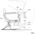
- the Figures 1 to 6 show a first exemplary embodiment of an aircraft seat device according to the invention.
- the aircraft seat device is designed as part of a partially shown aircraft seat module 10a.
- the aircraft seat module 10a includes an aircraft seat 12a.
- the aircraft seat 12a has a stand unit 14a, via which the aircraft seat 12a can be connected to a cabin floor of an aircraft.
- the aircraft seat 12a is preferably part of a row of seats with several aircraft seats arranged next to one another.
- the row of seats is designed as a front row of seats. There is no other row of seats directly in front of the row of seats designed as the front row of seats.
- the aircraft seat 12a includes a console 16a.
- the console 16a is arranged laterally next to the aircraft seat 12a.
- the console 16a forms an armrest.
- the console 16a forms a storage area.
- the storage area is located below the armrest.
- the aircraft seat device includes a functional unit 18a.
- the functional unit 18a is designed as a screen.
- the functional unit 18a is intended to be adjusted between a first position and at least a second position.
- the first position is designed as a stowed position of the functional unit 18a. In the first position, i.e. the stowed position, the functional unit 18a is arranged in the stowage area of the console 16a. In the first position, the functional unit 18a is not ready for operation. In the first position, the functional unit 18a is arranged next to the aircraft seat 12a, in particular in an area next to the stand unit 14a of the aircraft seat 12a.
- the second position is designed as a usage position of the functional unit 18a.
- the functional unit 18a In the second position, i.e. in the use position, the functional unit 18a can be used by a passenger sitting on the aircraft seat 12a.
- the functional unit 18a In the second position, the functional unit 18a is arranged in front of the aircraft seat 12a.
- the functional unit 18a designed as a screen In the second position, i.e. in the position of use, the functional unit 18a designed as a screen is arranged at a height of use in front of the aircraft seat 12a and faces the aircraft seat 12a.
- the functional unit 18a designed as a screen faces a seating area or a backrest of the aircraft seat 12a.
- the functional unit 18a designed as a screen is arranged in the position of use in a field of vision of a passenger sitting on the aircraft seat 12a.
- Figure 1 the position of use of the functional unit 18a is shown in dashed lines.
- the functional unit 18a can be pivoted between the first position and the second position.
- the functional unit 18a can be pivoted between the use position and the storage position.
- the functional unit 18a is pivotally connected to the aircraft seat device between the first position and the second position.
- the aircraft seat device has an adjustment module 20a.
- the adjustment module 20a is intended to adjustably connect the functional unit 18a to the aircraft seat module 10a.
- the adjustment module 20a is intended to adjust the functional unit 18a in an adjustment movement between the first position and the second position.
- the adjustment movement by means of which the functional unit 18a can be adjusted between its two positions, is designed as a pivoting movement. During the adjustment movement, the functional unit 18a is moved in a circular path.
- the adjustment module 20a includes a rotatably mounted holding arm 22a, at one end of which the functional unit 18a is arranged.
- the rotatably mounted holding arm 22a is connected to the aircraft seat 12a, in particular to the console 16a, with a first end. With its first end, the holding arm 22a is rotatably connected to the aircraft seat 12a, in particular to the console 16a. In principle, it would also be conceivable for the holding arm 22a to be connected to the aircraft seat 12a at a different location.
- the functional unit 18a is connected to the second end of the holding arm 22a.
- the rotatably mounted holding arm 22a is designed in several parts.
- the rotatably mounted holding arm 22a has a first sub-element 24a.
- the first sub-element 24a of the holding arm 22a is designed as a main pivoting element.
- the first sub-element 24a of the holding arm 22a is pivotally connected to the console 16a.
- the first sub-element 24a is pivotally connected with a first end to the aircraft seat 12a.
- the first end of the first sub-element 24a forms the first end of the holding arm 22a.
- the holding arm 22a has a second sub-element 26a.
- the second sub-element 26a is connected to a second end of the first sub-element 24a.
- the second sub-element 26a is pivotally connected to the first sub-element 24a.
- the second sub-element 26a is pivotally connected to the second end of the first sub-element 24a via a swivel joint.
- the second sub-element 26a is designed as an L-shaped element.
- the functional unit 18a is connected to a second end of the second sub-element 26a.
- the second end of the second sub-element 26a forms the second end of the holding arm 22a.
- the holding arm 22a has a different number of sub-elements, or is only formed by a single arm element.
- the adjustment module 20a has a pivot bearing 28a.
- the holding arm 22a is connected to the aircraft seat 12a via the pivot bearing 28a.
- the pivot bearing 28a is connected to a first end of the holding arm 22a.
- the pivot bearing 28a is connected to the first end of the first sub-element 24a of the holding arm 22a.
- the pivot bearing 28a has a first bearing element 30a which is connected to the aircraft seat 12a.
- the first bearing element 30a of the pivot bearing 28a is firmly mounted on the aircraft seat 12a, in particular on the console 16a.
- the first bearing element 30a comprises two walls spaced apart from one another, each of which has a bearing receptacle that is coaxially aligned with one another.
- the bearing receptacles of the first bearing element 30a form an axis of rotation of the pivot bearing 28a.
- the bearing receptacles of the first bearing element 30a are provided so that a correspondingly designed bearing element can be rotatably mounted therein.
- the pivot bearing 28a has a second bearing element 32a, which is firmly connected to the holding arm 22a.
- the second bearing element 32a is designed as a bearing pin.
- the second bearing element 32a is rotatably mounted in the bearing receptacles of the first bearing element 30a in a mounted state.
- the second bearing element 32a of the pivot bearing 28a is firmly attached to the first end of the holding arm 22a.
- the second bearing element 32a designed as a bearing pin, is firmly connected in a receptacle of the first sub-element 24a of the holding arm 22a.
- the two bearing elements 30a, 32a can be rotated relative to one another about the axis of rotation of the pivot bearing 28a.
- the holding arm 22a is rotatably connected to the aircraft seat 12a, in particular the aircraft seat module 10a, via the two bearing elements 30a, 32a of the pivot bearing 28a.
- the holding arm 22a and thus the functional unit 18a can be pivoted from the first position, designed as a stowed position, in an adjustment movement in a positive adjustment direction into the second position.
- the holding arm 22a and thus the functional unit 18a can be pivoted from the second position, designed as a position of use, in an adjustment movement in a negative adjustment direction into the first position.
- an adjustment force In order to pivot the functional unit 18a by means of the adjustment module 20a, an adjustment force must be exerted on the functional unit 18a and/or the adjustment module 20a.
- the adjustment force can be exerted by a passenger who applies the adjustment force by pushing or pulling on the functional unit 18a and/or the adjustment module 20a.
- the functional unit 18a and the adjustment module 20a can be moved, in particular from the first position, towards the second position.
- a negatively acting adjustment force the functional unit 18a and the adjustment module 20a can be moved, in particular from the second position, towards the first position, which is designed as a stowage position.
- the aircraft seat device includes a power support module 38a.
- the force support module 38a is intended to exert a support force on the adjustment module 20a.
- the force support module 38a is arranged at the first end of the adjustment module 20a.
- the force support module 38a is connected to the first end of the adjustment module 20a, in particular to the first end of the holding arm 22a.
- the force support module 38a is intended to exert a support force 40a on the adjustment module 20a in order to support an adjustment movement of the functional unit 18a between the first position and the second position.
- the force support module 38a is intended to provide the support force 40a both during an adjustment movement of the functional unit 18a from the first position to the second position and during an adjustment movement of the functional unit 18a from the second position to the first position.
- the supporting force 40a that is exerted on the adjustment module is variable.
- the supporting force 40a, which is exerted on the adjustment module 20a is in particular variable depending on a current position of the functional unit 18a.
- the supporting force 40a, which is exerted by the force supporting module 38a on the adjustment module 20a can act in a positive adjustment direction 34a as well as in a negative adjustment direction 36a.
- the support force 40a provided by the force support module 38a varies in size depending on the adjustment movement of the functional unit 18a, in particular in different positions of the functional unit 18a during the adjustment movement. As a result, an adjustment movement of the functional unit 18a in different positions of the functional unit 18a can be supported to varying degrees with the supporting force 40a by means of the force support module 38a.
- the force support module 38a is intended to convert an actuation force 42a into the variable support force 40a.
- the force support module 38a has a force storage 44a.
- the energy storage 44a is intended to provide the actuation force 42a.
- the energy storage 44a is designed as a gas pressure spring. In principle, it would also be conceivable for the energy accumulator 44a to be designed as another spring element.
- the energy storage 44a can provide a linearly acting actuation force.
- the energy storage 44a provides a substantially constant actuation force over its spring travel. In principle, however, it is also conceivable that the force accumulator 44a has a non-linear force curve, i.e. an actuation force is of different magnitude over the actuation path.
- the power support module 38a has an actuation gear 46a.
- the actuation gear 46a is intended to convert the actuation force 42a provided by the energy storage 44a into the variable support force 40a.
- the actuating gear 46a is designed as a cam gear.
- the actuating gear 46a is designed as a cam gear.
- the actuating gear 46a has a movably mounted cam element 48a.
- the movably mounted cam element 48a is intended to convert the actuating force 42a of the energy accumulator 44a into the supporting force 40a.
- the curve element 48a is intended to vary the support force 40a depending on an adjustment position.
- the movably mounted cam element 48a has a cam track 50a.
- the cam track 50a is formed by a cam track 52a, on which the actuating force 42a acts.
- the curved path 52a has different gradients, so that the actuation force is converted into the supporting force 40a differently depending on the gradient.
- the supporting force 40a is designed to be positive or negative depending on an angle of the cam track 50a.
- the cam element 48a is designed as a rotatably mounted cam disk.
- the cam element 48a designed as a cam disk, has a base circle 54a.
- the rotatably mounted cam element 48a has a bearing holder 56a.
- the cam element 48a is rotatably mounted via the bearing holder 56a.
- the cam element 48a is rotatably mounted on the aircraft seat 12a, in particular on the console 16a, via the bearing holder 56a.
- the bearing holder 56a is arranged at a center of the base circle 54a of the cam element 48a.
- the Bearing holder 56a forms a center of rotation of the cam element 48a designed as a cam disk.
- the cam track 50a is formed by the cam element 48a designed as a rotatably mounted cam disk.
- the cam track 50a is formed by a curved track 52a running in the circumferential direction.
- the cam track 50a has varying distances from the base circle 54a.
- the curved path 52a has different distances from the base circle 54a.
- the curved track 52a has different angles to the base circle 54a at different positions.
- the actuating gear 46a has an actuating element 58a.
- the actuating element 58a is intended to transmit the actuating force 42a to the cam track 50a of the cam element 48a. In a mounted state, the actuating element 58a rests on the cam track 50a of the cam element 48a.
- the actuating element 58a is designed as a rotatably mounted actuating wheel. When the cam element 48a, designed as a cam disk, rotates about its center of rotation, the actuating element 58a, designed as an actuating wheel, runs on the cam track 50a of the cam element 48a. This can advantageously avoid friction losses.
- the cam element 48a designed as a cam disk can advantageously simply rotate relative to the actuating element 58a.
- the force support module 38a has a pivotably mounted lever element 60a.
- the pivotally mounted lever element 60a is intended to transmit the actuating force 42a from the energy accumulator 44a to the actuating element 58a.
- the pivotally mounted lever element 60a has a bearing holder 62a, via which the lever element 60a is pivotally mounted.
- the lever element 60a is pivotally mounted relative to the force accumulator 44a and the cam element 48a via the bearing receptacle 62a and a suitable bearing element, such as in particular a bearing bolt.
- the lever element 60a is pivotally mounted to the aircraft seat 12a, in particular to the console 16a, via the bearing holder 62a and the bearing element.
- the lever element 60a has a triangle-like shape.
- the energy storage 44a is connected to the lever element 60a.
- the energy storage 44a is connected to the first end of the lever element 60a via a pivot bearing. This is at a second end of the lever element 60a
- Actuating element 58a connected to the lever element 60a.
- the actuating element 58a is rotatably connected to the lever element 60a.
- the bearing holder 62a via which the lever element 60a is pivotally mounted, is arranged between the connection of the actuating element 58a and the connection of the energy accumulator 44a.
- the bearing holder 62a is preferably attached off-center to the lever element 60a.
- the bearing holder 62a is preferably arranged outside a direct connecting line of the connections for the energy storage 44a and the actuating element 58a.
- the aircraft seat device includes a coupling unit 64a.
- the coupling unit 64a is intended to functionally couple the force support module 38a and the adjustment module 20a to one another.
- the coupling unit 64a is intended to transmit the support force 40a provided by the force support module 38a to the adjustment module 20a.
- the coupling unit 64a is intended to transmit the supporting force 40a from the cam element 48a to the holding arm 22a of the adjustment module 20a.
- the coupling unit 64a connects the cam element 48a and the holding arm 22a of the adjustment module 20a to one another in terms of movement.
- the coupling unit 64a connects the cam element 48a and the holding arm 22a of the adjustment module 20a to one another in a rotationally fixed manner.
- the coupling unit 64a is formed by a wrapping element 66a.
- the wrapping element 66a is designed as a belt.
- the wrapping element 66a designed as a belt, surrounds the cam element 48a, designed as a cam disk, in a coupling area.
- the wrapping element 66a designed as a belt, also encompasses a bearing area of the rotatably mounted holding arm 22.
- the rotatably mounted holding arm 22 can be rotated via the wrapping element 66a.
- the wrapping element 66a preferably engages directly on the pivot bearing 28a of the first sub-element 24a of the holding arm 22a.
- the actuating force exerted by the energy accumulator 44a on the cam track 50a of the cam element 48a is aligned with the center of rotation of the cam element 48a designed as a cam disk.
- the actuating force 42a transmitted from the energy accumulator 44a to the cam track 50a of the cam element 48a is formed on the center of rotation of the cam element 48a designed as a cam disk, regardless of an angular position of the cam element 48a.
- the cam track 50a which extends in the circumferential direction of the cam element 48a viewed as having different heights from the base circle 54a, therefore does not run parallel to the base circle 54a. There is an angular offset between the cam track 50a and the base circle 54a of the cam element 48a.
- the angular offset between the cam track 50a which is designed as a cam track 52a, is in the Figures 4 to 6 to recognize.
- a cam stroke of the cam track 50a is shown as a function of the rotation angle of the cam element 48a.
- the cam track 50a has different inclinations to the base circle 54a at different angles of rotation of the cam element 48a.
- the cam track 50a has different inclinations when viewed in the circumferential direction.
- a force component 70a acting in the circumferential direction results from the actuating force 44a of the force accumulator acting in the direction of the center of rotation of the cam element 48a on the cam track 50a.
- the force component 70a acting in the circumferential direction is formed as a torque acting on the cam element 48a.
- the force component 70a forms the supporting force 40a.
- the force component 70a resulting from the actuation force 44a, which forms the supporting force 40a is dependent on an inclination of the cam track 50a.
- the acting actuating force 42a results in a different supporting force 44a depending on the angle of rotation.
- the resulting force component 70a and thereby the supporting force 44a can act both in a first direction of rotation of the curve element 48a and in a second direction of rotation that is opposite to the first direction of rotation.
- the supporting force 44a can be designed to be positive or negative depending on the angle of the cam track 50a.
- An adjustment movement of the functional unit 18a can be supported to varying degrees by the supporting force 44a in different phases of the adjustment, that is to say in different adjustment positions of the functional unit 18a.
- the adjustment movement of the functional unit 18a can be accelerated or braked in different adjustment positions of the functional unit 18a by the supporting force 44a.
- the Figure 7 shows part of an aircraft seat device according to the invention in a second exemplary embodiment.
- the aircraft seat device is designed as a part of an aircraft seat module, not shown.
- the aircraft seat device includes a functional unit, not shown in detail.
- the functional unit is designed as a screen.
- the functional unit is intended to be adjusted between a first position and at least a second position.
- the functional unit can be pivoted between the first position and the second position.
- the aircraft seat device has an adjustment module 20b.
- the adjustment module 20b is intended to connect the functional unit to the aircraft seat module in an adjustable manner.
- the adjustment module 20b comprises a rotatably mounted holding arm, at one end of which the functional unit is arranged.
- the functional unit and the adjustment module can be designed essentially the same as in the first exemplary embodiment.
- the aircraft seat device includes a power support module 38b.
- the force support module 38b is intended to exert a support force on the adjustment module 20b.
- the force support module 38b is also designed essentially the same as in the first exemplary embodiment.
- the force support module 38b has a force storage 44b.
- the energy storage 44b is intended to provide an actuation force 42b.
- the energy storage 44b is designed as a gas pressure spring.
- the power support module 38b has an actuation gear 46b.
- the actuation gear 46b is intended to convert the actuation force 42b provided by the energy storage 44b into the variable support force 40b.
- the actuating gear 46b is designed as a cam gear.
- the actuating gear 46b has a movably mounted cam element 48b.
- the movably mounted cam element 48b is intended to convert the actuating force 42b of the energy accumulator 44b into a supporting force 40b.
- a cam element 48b is provided to vary the support force 40b depending on an adjustment position.
- the cam element 48b is designed as a rotatably mounted cam disk.
- the actuating gear 46b has an actuating element 58b.
- the actuating element 58b is intended to transmit the actuating force 42b to the cam track 50b of the cam element 48b.
- the force support module 38b has a pivotably mounted lever element 60b.
- the pivotally mounted lever element 60b is intended to transmit the actuating force 42b from the energy storage 44b to the actuating element 58b.
- the aircraft seat device includes a coupling unit 64b.
- the coupling unit 64b is intended to functionally couple the force support module 38b and the adjustment module 20b to one another.
- the coupling unit 64b is intended to transmit the support force 40b provided by the force support module 38b to the adjustment module 20b.
- the coupling unit 64b is designed as a gear transmission.
- the coupling unit 64b has a first gear element 72b.
- the first gear element 72b is connected to the cam element in a rotationally fixed manner.
- the first gear element 72b is designed as a spur gear.
- the coupling unit 64b has a second gear element 74b.
- the second gear element 74b is pivotably mounted.
- the second gear element 74b is intended to be coupled to the adjustment module 20b.
- the second gear element 74b is designed as a partial gear with spur teeth.
- the second gear element 74b meshes with its spur gear teeth in the first gear element 72b, which is designed as a spur gear.
- the adjustment module 20b has a coupling element 76b, via which the coupling unit 64b is connected to the adjustment module 20b.
- the coupling element 76b is designed as a coupling rod.
- the coupling element 76b, designed as a coupling rod is connected at a first end to the second gear element 74b. At one At the second end, the coupling element 76b, designed as a coupling rod, is coupled to the holding arm, not shown, of the adjustment module 20b.
- a mode of operation of the force support module 38b and the adjustment module 20b for adjusting the functional unit is essentially the same as in the first exemplary embodiment and will therefore not be described in more detail here. Reference is made here to the corresponding description of the first exemplary embodiment.
- the Figures 8 and 9 show a third embodiment of an aircraft seat device according to the invention.
- the aircraft seat device is designed as part of a partially shown aircraft seat module 10c.
- the aircraft seat module 10c includes an aircraft seat 12c.
- the aircraft seat 12c has a stand unit 14c, via which the aircraft seat 12c can be connected to a cabin floor of an aircraft.
- the aircraft seat 12c has an aircraft seat element 78c designed as a seat floor.
- the aircraft seat element 78c designed as a seat base, is coupled to the stand unit 14c.
- the aircraft seat 12c has a further aircraft seat element 80c.
- the further aircraft seat element 80c is designed as a backrest.
- the aircraft seat device includes a functional unit 18c.
- the functional unit 18c is designed differently in contrast to the previous exemplary embodiments.
- the functional unit 18c is designed as the aircraft element 80c, which is designed as a backrest.
- the functional unit 18c is designed as the backrest of the aircraft seat 12c.
- the functional unit 18c designed as a backrest is pivotally coupled to the stand unit 14c.
- the functional unit 18c, designed as a backrest is intended to be pivoted by a passenger sitting on the aircraft seat 12c. By pivoting the functional unit 18c designed as a backrest, an upright sitting position (TTL position) and at least one comfort position of the aircraft seat 12c can be provided.
- TTL position upright sitting position
- at least one comfort position of the aircraft seat 12c can be provided.
- the aircraft seat device has an adjustment module 20c.
- the adjustment module 20c is intended to adjustably connect the functional unit 18c, i.e. the aircraft seat element 80c designed as a backrest, to the aircraft seat module 10c, in particular to the stand unit 14c of the aircraft seat 12c.
- the adjustment module 20c has a storage unit 82c, via which the functional unit 18c designed as a backrest is rotatably connected to the stand unit 14c.
- the storage unit 82c comprises two bearing elements, not shown, which laterally support the functional unit 18c designed as a backrest.
- the adjustment module 20c can preferably include an energy storage device 68c.
- the energy storage 68c is designed as a gas pressure spring.
- the energy storage 68c is intended to provide a restoring force for the functional unit 18c, i.e. the aircraft seat element 80c designed as a backrest.
- the energy storage 68c is functionally arranged between the stand unit and the functional unit 18c.
- the aircraft seat device includes a power support module 38c.
- the force support module 38c is intended to exert a support force on the adjustment module 20c.
- the force support module 38c is also designed essentially the same as in the first exemplary embodiment.
- the force support module 38c has a force storage 44c.
- the energy storage 44c is intended to provide the actuation force 42c.
- the energy storage 44c is designed as a gas pressure spring.
- the power support module 38c has an actuation gear 46c.
- the actuation gear 46c is intended to convert the actuation force 42c provided by the energy storage 44c into the variable support force 40c.
- the actuating gear 46c is designed as a cam gear.
- the actuating gear 46c has a movably mounted cam element 48c.
- the movably mounted cam element 48c is intended to convert the actuating force 42c of the energy accumulator 44c into a supporting force 40c.
- the curve element 48c is intended to vary the support force 40c depending on an adjustment position.
- the cam element 48c is designed as a rotatably mounted cam disk.
- the actuating gear 46c has an actuating element 58c.
- the actuating element 58c is intended to transmit the actuating force 42c to the cam track 50c of the cam element 48c.
- the force support module 38c has a pivotably mounted lever element 60c.
- the pivotally mounted lever element 60c is intended to transmit the actuating force 42c from the energy storage 44c to the actuating element 58c.
- the aircraft seat device includes a coupling unit 64c.
- the coupling unit 64c is intended to functionally couple the force support module 38c and the adjustment module 20c to one another.
- the coupling unit 64c is intended to transmit the support force 40c provided by the force support module 38c to the adjustment module 20c.
- the coupling unit 64c is designed here, for example, in the same way as in the second exemplary embodiment.
- the coupling unit 64c is designed as a gear transmission.
- the coupling unit 64c has a first gear element 72c.
- the first gear element 72c is connected to the cam element 48c in a rotationally fixed manner.
- the coupling unit 64c has a second gear element 74c.
- the second gear element 74c is pivotably mounted.
- the second gear element 74c is intended to be coupled to the adjustment module 20c.
- the adjustment module 20c has a coupling element 76c, via which the coupling unit 64c is connected to the adjustment module 20c.
- the coupling element 76c is designed as a coupling rod.
- the coupling element 76c designed as a coupling rod, is connected at a first end to the second gear element 74c.
- the adjustment module 20c has a coupling arm 84c.
- the coupling arm 84c is connected to a second end of the coupling element 76c.
- the coupling arm 84c is connected to the functional unit 18c designed as a backrest.
- the supporting force 40c of the force supporting module 38c is transmitted to the functional unit 18c designed as a backrest via the coupling arm 84c.
- the support force 40c of the force support module 38c can support an adjustment movement of the functional unit 18c designed as a backrest.
- the supporting force provided by the force support module 38c is preferably intended to support the energy storage unit 68c for adjusting the aircraft seat element 80c designed as a backrest.
- a mode of operation of the force support module 38c and the adjustment module 20c for adjusting the functional unit 18c is essentially the same as in the first exemplary embodiment and will therefore not be described in more detail here. Reference is made here to the corresponding description of the first exemplary embodiment.
- the Figure 10 shows part of an aircraft seat device according to the invention in a fourth exemplary embodiment.
- the aircraft seat device is designed as a part of an aircraft seat module, not shown.
- the aircraft seat device includes a functional unit, not shown in detail.
- the functional unit is designed as a screen.
- the functional unit is intended to be adjusted between a first position and at least a second position.
- the aircraft seat device has an adjustment module 20d.
- the adjustment module 20d is intended to connect the functional unit to the aircraft seat module in an adjustable manner.
- the aircraft seat device includes a power support module 38d.
- the force support module 38d is intended to exert a support force on the adjustment module.
- the force support module 38d essentially has the same functional principle as in the previous exemplary embodiments. However, in contrast to the previous exemplary embodiments, the force support module 38d has differences that will be briefly explained below.
- the force support module 38d is intended to convert an actuation force 42d into a variable support force 40d.
- the force support module 38d has a force storage 44d.
- the energy storage 44d is intended to provide the actuation force 42d.
- the power support module 38d has an actuation gear 46d.
- the actuation gear 46d is intended to convert the actuation force 42d provided by the energy storage 44d into the variable support force 40d.
- the actuating gear 46d is designed as a cam gear.
- the actuating gear 46d has a movably mounted cam element 48d.
- the movably mounted cam element 48d is intended to convert the actuating force 42d of the energy accumulator 44d into the supporting force 40d.
- the movably mounted cam element 48d is designed as a linearly displaceable linear guide element.
- the curve element 48d which is designed as a linearly displaceable linear guide element, can be linearly displaceable along a displacement axis.
- the curve element 48d has an elongated basic shape.
- the curve element 48d is formed by an elongated base body 86d.
- the base body 86d of the cam element 48d forms a guide rail.
- the guide rail of the cam element 48d forms the displacement axis.
- the curve element 48d is mounted in a linearly displaceable manner in an equivalently designed guide rail via the guide rail.
- the cam element 48d has a cam track 50d.
- the cam track 50d is arranged on an upper side of the base body 86d of the cam element 48d.
- the cam track 50d is designed as a cam track 52d.
- the cam track 50d has a curved course along a main extent of the curve element 48d.
- the cam track 50d has different inclinations in different areas.
- the actuating gear 46d has an actuating element 58d.
- the actuating element 58d is intended to transmit the actuating force 42d to the cam track 50d of the cam element 48d.
- the actuating element 58d is intended to exert the actuating force 42d on the cam track 50d at a right angle to the main extension direction of the cam element 48d.
- a resulting force component 70d is generated along the displacement axis of the cam element 48d depending on the inclination of the cam track 50d.
- the size and direction of the force component 70d depends on the corresponding inclination of the cam track 50d at which the actuating element 58d introduces the force into the cam track 50d.
Landscapes
- Engineering & Computer Science (AREA)
- Aviation & Aerospace Engineering (AREA)
- Transportation (AREA)
- Mechanical Engineering (AREA)
- Chairs For Special Purposes, Such As Reclining Chairs (AREA)
Abstract
Die Erfindung geht aus von einer Flugzeugsitzvorrichtung mit einer Funktionseinheit, mit einem Verstellmodul, über das die Funktionseinheit zumindest zwischen einer ersten Stellung und einer zweiten Stellung verstellbar ist, mit einem Kraftunterstützungsmodul, das dazu vorgesehen ist, in einem betätigten Zustand eine Unterstützungskraft auf das Verstellmodul auszuüben, um eine Verstellbewegung der Funktionseinheit zwischen der ersten Stellung und der zweiten Stellung zu unterstützen, wobei das Kraftunterstützungsmodul dazu zumindest einen Kraftspeicher aufweist.Es wird vorgeschlagen, dass das Kraftunterstützungsmodul ein Betätigungsgetriebe mit einem beweglich gelagerten Kurvenelement aufweist, wobei das Kurvenelement eine Nockenbahn ausbildet und dazu vorgesehen ist, die Unterstützungskraft in einer Abhängigkeit einer Verstellposition zu variieren.The invention is based on an aircraft seat device with a functional unit, with an adjustment module, via which the functional unit can be adjusted at least between a first position and a second position, with a force support module, which is intended to exert a support force on the adjustment module in an actuated state in order to support an adjustment movement of the functional unit between the first position and the second position, the force support module having at least one energy accumulator for this purpose. It is proposed that the force support module has an actuation gear with a movably mounted cam element, the cam element forming a cam track and also It is provided to vary the support force depending on an adjustment position.
Description
Die Erfindung betrifft eine Flugzeugsitzvorrichtung nach dem Oberbegriff des Patentanspruchs 1.The invention relates to an aircraft seat device according to the preamble of
Es ist bereits eine Flugzeugsitzvorrichtung mit einer Funktionseinheit, mit einem Verstellmodul, über das die Funktionseinheit zumindest zwischen einer ersten Stellung und einer zweiten Stellung verstellbar ist, mit einem Kraftunterstützungsmodul, das dazu vorgesehen ist, in einem betätigten Zustand eine Unterstützungskraft auf das Verstellmodul auszuüben, um eine Verstellbewegung der Funktionseinheit zwischen der ersten Stellung und der zweiten Stellung zu unterstützen, wobei das Kraftunterstützungsmodul dazu zumindest einen Kraftspeicher aufweist, vorgeschlagen worden.There is already an aircraft seat device with a functional unit, with an adjustment module, via which the functional unit can be adjusted at least between a first position and a second position, with a force support module, which is intended to exert a support force on the adjustment module in an actuated state to support an adjustment movement of the functional unit between the first position and the second position, with the force support module having at least one energy storage for this purpose.
Die Aufgabe der Erfindung besteht insbesondere darin, eine gattungsgemäße Vorrichtung mit verbesserten Eigenschaften hinsichtlich eines Komforts für einen Passagier bereitzustellen. Die Aufgabe wird erfindungsgemäß durch die Merkmale des Patentanspruchs 1 gelöst, während vorteilhafte Ausgestaltungen und Weiterbildungen der Erfindung den Unteransprüchen entnommen werden können.The object of the invention is, in particular, to provide a generic device with improved properties in terms of comfort for a passenger. The object is achieved according to the invention by the features of
Die Erfindung geht aus von einer Flugzeugsitzvorrichtung mit einer Funktionseinheit, mit einem Verstellmodul, über das die Funktionseinheit zumindest zwischen einer ersten Stellung und einer zweiten Stellung verstellbar ist, mit einem Kraftunterstützungsmodul, das dazu vorgesehen ist, in einem betätigten Zustand eine Unterstützungskraft auf das Verstellmodul auszuüben, um eine Verstellbewegung der Funktionseinheit zwischen der ersten Stellung und der zweiten Stellung zu unterstützen, wobei das Kraftunterstützungsmodul dazu zumindest einen Kraftspeicher aufweist.The invention is based on an aircraft seat device with a functional unit, with an adjustment module, via which the functional unit can be adjusted at least between a first position and a second position, with a force support module, which is intended to exert a support force on the adjustment module in an actuated state in order to support an adjustment movement of the functional unit between the first position and the second position, the force support module having at least one force accumulator for this purpose.
Es wird vorgeschlagen, dass das Kraftunterstützungsmodul ein Betätigungsgetriebe mit einem beweglich gelagerten Kurvenelement aufweist, wobei das Kurvenelement eine Nockenbahn ausbildet und dazu vorgesehen ist, die Unterstützungskraft in einer Abhängigkeit einer Verstellposition zu variieren. Unter einer "Flugzeugsitzvorrichtung" soll eine Vorrichtung verstanden werden, die zumindest einen Teil eines Flugzeugsitzes oder einen Teil eines Flugzeugsitzmoduls ausbildet. Ein Flugzeugsitzmodul ist vorzugsweise ein Modul mit einem Flugzeugsitz und weiteren Bauteilen, wie beispielsweise einem Umhausungselement, einer Konsole oder einen Ottomane. Unter einer "Funktionseinheit" soll ein funktionaler Teil des Flugzeugsitzes oder des Flugzeugsitzmoduls verstanden werden, der von einem Passagier genutzt werden kann. Eine Funktionseinheit kann als ein Bildschirm, als ein Flugzeugsitzelement, wie insbesondere eine Rückenlehne, ein Fußstützelement, oder ein Bankelement, oder als ein anderes zwischen zumindest zwei Stellungen bewegbar gelagertes Bauteil eines Flugzeugsitzes sein, das von einem Passagier zwischen den beiden Stellungen verstellt werden kann. Unter einem "Kraftunterstützungsmodul" soll ein Modul verstanden werden, das zur Unterstützung einer Verstellbewegung einer Funktionseinheit zwischen zumindest zwei Stellungen vorgesehen ist und dazu zumindest eine Unterstützungskraft bereitstellt, die auf die Funktionseinheit wirkt. Unter einer "Unterstützungskraft" soll eine Kraft verstanden werden, die eine Bewegung der Funktionseinheit unterstützt, wobei diese Kraft dabei vorzugsweise eine Verstellbewegung der Funktionseinheit beschleunigen oder verzögern kann. Unter einem "Kraftspeicher" soll ein Element verstanden werden, das dazu vorgesehen ist, in zumindest einem Betätigungszustand eine Betätigungskraft F bereitzustellen. Vorzugsweise ist der Kraftspeicher als ein Federelement ausgebildet, das durch Stauchung entgegen einer Kraftrichtung der Betätigungskraft eine Kraft speichern kann. Der Kraftspeicher kann als eine mechanische Feder ausgebildet sein, die durch eine elastische Verformung eine Betätigungskraft speichert. Vorteilhaft ist der Kraftspeicher als eine Fluiddruckfeder, insbesondere als eine Gasdruckfeder ausgebildet. Unter einem "Betätigungsgetriebe" soll vorzugsweise ein Übersetzungsgetriebe verstanden werden, das eine erste Kraft und/oder Bewegung in eine zweite Kraft und/oder Bewegung umsetzt. Unter einem "Kurvenelement" soll vorzugsweise ein Element verstanden werden, das zumindest eine Erhebung aufweist, die sich von einer Grundfläche des Kurvenelements erhebt. Das Kurvenelement bildet vorzugsweise zumindest einen Teil eines Kurvengetriebes aus. Das Kurvenelement kann eine ebene Grundfläche aufweisen und als eine linear verschiebbare Kurvenstange ausgebildet sein.It is proposed that the force support module has an actuation gear with a movably mounted cam element, wherein the cam element forms a cam track and is intended to vary the support force depending on an adjustment position. An “aircraft seat device” is to be understood as meaning a device that forms at least part of an aircraft seat or part of an aircraft seat module. An aircraft seat module is preferably a module with an aircraft seat and other components, such as a housing element, a console or an ottoman. A “functional unit” is intended to mean a functional part of the aircraft seat or aircraft seat module that can be used by a passenger. A functional unit can be a screen, an aircraft seat element, such as in particular a backrest, a footrest element, or a bench element, or as another component of an aircraft seat that is movably mounted between at least two positions and can be adjusted by a passenger between the two positions. A “force support module” is to be understood as meaning a module that is provided to support an adjustment movement of a functional unit between at least two positions and for this purpose provides at least one support force that acts on the functional unit. A “supporting force” is to be understood as meaning a force that supports a movement of the functional unit, whereby this force can preferably accelerate or delay an adjustment movement of the functional unit. A “force storage” is to be understood as an element that is intended to provide an actuation force F in at least one actuation state. The force accumulator is preferably designed as a spring element which can store a force by compression against a force direction of the actuating force. The energy storage can be designed as a mechanical spring that stores an actuation force through elastic deformation. The force accumulator is advantageously designed as a fluid pressure spring, in particular as a gas pressure spring. An “actuating gear” should preferably be understood as meaning a transmission gear that converts a first force and/or movement into a second force and/or movement. A “curve element” should preferably be understood to mean an element that has at least one elevation that rises from a base surface of the curve element. The cam element preferably forms at least part of a cam mechanism. The curve element can have a flat base and be designed as a linearly displaceable curve rod.
Das als verschiebbare Kurvenstange ausgebildete Kurvenelement ist als eine axial verschiebbare Stange ausgebildet, das auf einer Seite eine Nockenbahn ausbildet. Vorzugsweise weist das Kurvenelement eine Grundfläche auf, die von einer Mantelfläche eines Kreiszylinders gebildet ist. Vorzugsweise ist das Kurvenelement als ein Nockenelement ausgebildet. Unter einer "Nockenbahn" soll eine Oberfläche des Kurvenelements verstanden werden, das zu einem Kontakt mit einem weiteren Element, wie insbesondere einem Betätigungselement vorgesehen ist. Die Nockenbahn ist als eine Kurvenbahn ausgebildet. Die Nockenbahn weist im Bereich der Erhebung entlang ihrer Haupterstreckung vorzugsweise unterschiedliche Winkel zu der Grundfläche des Kurvenelements auf. Unter einer "Verstellposition" soll vorzugsweise insbesondere eine relative Position eines Elements zu einem zweiten Element während eines diskreten Zeitpunkts einer Verstellung verstanden werden. Unter einer Verstellposition des Kurvenelements soll eine relative Position des Kurvenelements zu dem Kraftspeicher bzw. zu einem Betätigungselement, das in Kontakt mit der Nockenbahn steht und eine Betätigungskraft auf das Kurvenelement überträgt, verstanden werden. Unter "vorgesehen" soll insbesondere speziell ausgelegt und/oder ausgestattet verstanden werden. Darunter, dass ein Objekt zu einer bestimmten Funktion vorgesehen ist, soll insbesondere verstanden werden, dass das Objekt diese bestimmte Funktion in zumindest einem Anwendungs- und/oder Betriebszustand erfüllt und/oder ausführt. Durch eine erfindungsgemäße Ausgestaltung kann vorteilhaft ein Mechanismus bereitgestellt werden, mittels dem ein Funktionsbauteil besonders einfach zwischen zumindest zwei Stellungen verstellt werden kann. Insbesondere kann ein besonders vorteilhafter Mechanismus bereitgestellt werden, in dem eine Unterstützungskraft besonders vorteilhaft in unterschiedlichen Bereichen der Verstellung unterschiedlich wirken und die Verstellung so zu unterschiedlichen Zeitpunkten der Verstellung unterschiedlich unterstützen kann.The cam element designed as a displaceable cam rod is designed as an axially displaceable rod which forms a cam track on one side. The curve element preferably has a base area which is formed by a lateral surface of a circular cylinder. The cam element is preferably designed as a cam element. A “cam track” is to be understood as meaning a surface of the cam element that is intended to come into contact with another element, such as in particular an actuating element. The cam track is designed as a curved track. The cam track preferably has different angles to the base of the curve element in the area of the elevation along its main extension. An “adjustment position” should preferably be understood to mean, in particular, a relative position of an element to a second element during a discrete point in time of an adjustment. An adjustment position of the cam element is to be understood as meaning a relative position of the cam element to the energy storage or to an actuating element that is in contact with the cam track and transmits an actuating force to the cam element. “Provided” is intended to mean, in particular, specifically designed and/or equipped. The fact that an object is intended for a specific function should be understood in particular to mean that the object fulfills and/or executes this specific function in at least one application and/or operating state. An embodiment according to the invention can advantageously provide a mechanism by means of which a functional component can be adjusted particularly easily between at least two positions. In particular, a particularly advantageous mechanism can be provided in which a supporting force can act particularly advantageously differently in different areas of the adjustment and can thus support the adjustment differently at different times of the adjustment.
Weiter wird vorgeschlagen, dass eine Unterstützungskraft in Abhängigkeit eines Winkels der Nockenbahn positiv oder negativ ausgebildet ist. Unter einer "positiven Unterstützungskraft" soll eine Kraft verstanden werden, die eine Verstellbewegung der Funktionseinheit beschleunigt und eine Verstellung dadurch erleichtert. Unter einer "negativen Unterstützungskraft" soll eine Kraft verstanden werden, die eine Verstellbewegung der Funktionseinheit verzögert und so eine Verstellung abbremst. Dadurch kann eine Verstellbewegung der Funktionseinheit besonders vorteilhaft unterstützt werden, insbesondere kann die Unterstützungskraft in Abhängigkeit der aktuellen Position der Funktionseinheit besonders vorteilhaft angepasst werden.It is further proposed that a supporting force is designed to be positive or negative depending on an angle of the cam track. A “positive supporting force” is to be understood as meaning a force that accelerates an adjustment movement of the functional unit and thereby makes adjustment easier. A “negative support force” is to be understood as meaning a force that delays an adjustment movement of the functional unit and thus slows down an adjustment. This makes an adjustment movement of the functional unit particularly advantageous are supported, in particular the support force can be adapted particularly advantageously depending on the current position of the functional unit.
Ferner wird vorgeschlagen, dass das beweglich gelagerte Kurvenelement als eine drehbar gelagerte Nockenscheibe ausgebildet ist. Unter einer "Nockenscheibe" soll eine Scheibe verstanden werden, die an ihrem Außenumfang einen Nocken ausbildet, der eine Kurvenbahn ausbildet. Dadurch kann das Kurvenelement besonders vorteilhaft ausgebildet werden, insbesondere zur Erzeugung einer Unterstützungskraft für eine Verschwenkbewegung des Funktionsbauteils.Furthermore, it is proposed that the movably mounted cam element is designed as a rotatably mounted cam disk. A “cam disk” is to be understood as a disk that forms a cam on its outer circumference, which forms a curved path. As a result, the curve element can be designed particularly advantageously, in particular for generating a supporting force for a pivoting movement of the functional component.
Es wird weiterhin vorgeschlagen, dass das als Nockenscheibe ausgebildete Kurvenelement einen Grundkreis aufweist, wobei die Nockenbahn von einer in Umfangsrichtung verlaufenden Kurvenbahn gebildet ist, die variierende Abstände zu dem Grundkreis aufweist. Dadurch kann das als Nockenscheibe ausgebildete Kurvenelement besonders vorteilhaft ausgebildet werden.It is further proposed that the cam element designed as a cam disk has a base circle, the cam track being formed by a cam track running in the circumferential direction and having varying distances from the base circle. As a result, the cam element designed as a cam disk can be designed particularly advantageously.
Des Weiteren wird vorgeschlagen, dass eine von dem Kraftspeicher auf die Nockenbahn des Kurvenelements ausgeübte Betätigungskraft auf einen Rotationsmittelpunkt des als Nockenscheibe ausgebildeten Kurvenelements ausgerichtet ist. Dadurch kann die auf das Kurvenelement ausgeübte Betätigungskraft besonders vorteilhaft auf das Kurvenelement wirken.Furthermore, it is proposed that an actuating force exerted by the energy accumulator on the cam track of the cam element is aligned with a center of rotation of the cam element designed as a cam disk. As a result, the actuating force exerted on the cam element can have a particularly advantageous effect on the cam element.
Weiterhin wird vorgeschlagen, dass das Betätigungsgetriebe ein Betätigungselement aufweist, das dazu vorgesehen ist, eine von dem Kraftspeicher bereitgestellte Betätigungskraft auf die Nockenbahn des Kurvenelements zu übertragen. Unter einem "Betätigungselement" soll vorzugsweise ein Element verstanden werden, das zur Übertragung einer Kraft auf ein anderes Element vorgesehen ist und dazu auf einer entsprechenden Fläche des anderen Elements aufliegt. Das Betätigungselement ist vorzugsweise als ein drehbar gelagertes Übertragungsrad ausgebildet, das auf der Nockenbahn des Kurvenelements bei einer Verdrehung des Kurvenelements abrollen kann. Dadurch kann eine Übertragung der Kraft auf das Kurvenelement besonders vorteilhaft erfolgen und vorteilhaft Reibungsverluste bei der Kraftübertragung verringert werden.Furthermore, it is proposed that the actuating gear has an actuating element which is intended to transmit an actuating force provided by the energy accumulator to the cam track of the cam element. An “actuating element” should preferably be understood as meaning an element that is intended to transmit a force to another element and for this purpose rests on a corresponding surface of the other element. The actuating element is preferably designed as a rotatably mounted transmission wheel, which can roll on the cam track of the cam element when the cam element is rotated. As a result, the force can be transferred to the curve element particularly advantageously and friction losses during the force transmission can be advantageously reduced.
Außerdem wird vorgeschlagen, dass das Kraftunterstützungsmodul ein schwenkbar gelagertes Hebelelement aufweist, das dazu vorgesehen ist, eine Betätigungskraft von dem Kraftspeicher auf das Betätigungselement zu übertragen. Dadurch kann eine Betätigungskraft besonders vorteilhaft von dem Kraftspeicher auf das Betätigungselement übertragen werden, wobei die Kraft vorteilhaft übersetzt werden kann.It is also proposed that the force support module has a pivotally mounted lever element which is intended to transmit an actuation force from the force storage to the actuation element. As a result, an actuating force can be transferred particularly advantageously from the energy storage to the actuating element, whereby the force can be advantageously translated.
Es wird weiter vorgeschlagen, dass die Flugzeugsitzvorrichtung zumindest eine Kopplungseinheit aufweist, die das Kraftunterstützungsmodul und das Verstellmodul miteinander funktional koppelt. Unter einer "Kopplungseinheit" soll vorzugsweise eine Einheit verstanden werden, die eine Kraft und Bewegung zwischen zumindest zwei Komponenten überträgt. Die Kopplungseinheit ist dazu vorgesehen, eine Bewegung des Kurvenelements auf das Verstellmodul zu übertragen. Die Kopplungseinheit ist dazu vorgesehen, die von dem Kraftunterstützungsmodul bereitgestellte Unterstützungskraft auf das Verstellmodul zu übertragen. Dadurch kann das Kraftunterstützungsmodul vorteilhaft beabstandet von dem Verstellmodul angeordnet werden, wodurch insbesondere eine vorteilhafte Ausnutzung eines Bauraums erfolgen kann.It is further proposed that the aircraft seat device has at least one coupling unit that functionally couples the force support module and the adjustment module to one another. A “coupling unit” should preferably be understood as meaning a unit that transmits force and movement between at least two components. The coupling unit is intended to transmit a movement of the cam element to the adjustment module. The coupling unit is intended to transmit the support force provided by the force support module to the adjustment module. As a result, the force support module can advantageously be arranged at a distance from the adjustment module, which in particular allows an advantageous use of installation space.
Zudem wird vorgeschlagen, dass die Kopplungseinheit von einem Umschlingungselement ausgebildet ist. Unter einem "Umschlingungselement" soll ein Element verstanden werden, das zumindest zwei drehbare Bauteile durch eine Umschlingung miteinander koppelt. Das Umschlingungselement ist vorzugsweise als ein Riemen ausgebildet. Grundsätzlich ist es denkbar, dass das Umschlingungselement als ein einfacher Riemen oder als ein Zahnriemen ausgebildet ist. Grundsätzlich wäre es auch denkbar, dass das Umschlingungselement als eine Kette ausgebildet ist. Dadurch kann die Kopplungseinheit besonders vorteilhaft einfach ausgebildet werden.It is also proposed that the coupling unit is formed by a wrapping element. A “wrap element” is to be understood as an element that couples at least two rotatable components to one another through a wrap. The wrapping element is preferably designed as a belt. In principle, it is conceivable that the wrapping element is designed as a simple belt or as a toothed belt. In principle, it would also be conceivable for the wrapping element to be designed as a chain. As a result, the coupling unit can be designed to be particularly advantageously simple.
Weiter wird vorgeschlagen, dass die Kopplungseinheit als eine Zahnradübersetzung ausgebildet ist. Unter einer "Zahnradübersetzung" soll vorzugsweise eine Übersetzung einer Kraft mittels zumindest zweier ineinandergreifender Zahnräder verstanden werden. Die als Zahnradübersetzung ausgebildete Kopplungseinheit weist vorzugsweise ein erstes Zahnrad, das drehfest mit dem Kurvenelement verbunden ist, und ein in das erste Zahnrad eingreifendes zweites Zahnrad auf, das mit dem Verstellmodul drehfest verbunden ist. Dadurch kann die Kopplungseinheit besonders robust ausgebildet werden.It is further proposed that the coupling unit is designed as a gear transmission. A “gear transmission” should preferably be understood as a translation of a force by means of at least two interlocking gears. The coupling unit designed as a gear transmission preferably has a first gear that is connected in a rotationally fixed manner to the cam element, and a second gear that engages in the first gear and is connected in a rotationally fixed manner with the adjustment module. As a result, the coupling unit can be designed to be particularly robust.
Ferner wird vorgeschlagen, dass das Verstellmodul zumindest einen drehbar gelagerten Haltearm aufweist, an dessen einem Ende die Funktionseinheit angeordnet ist und an dessen anderem Ende das Kraftunterstützungsmodul angeordnet ist. Dadurch kann das Verstellmodul besonders vorteilhaft zur schwenkbaren Lagerung der Funktionseinheit ausgebildet werden.Furthermore, it is proposed that the adjustment module has at least one rotatably mounted holding arm, at one end of which the functional unit is arranged and at the other end of which the force support module is arranged. As a result, the adjustment module can be designed particularly advantageously for the pivotable mounting of the functional unit.
Es wird weiterhin vorgeschlagen, dass die Funktionseinheit als ein Bildschirm ausgebildet ist. Dadurch kann die Funktionseinheit besonders vorteilhaft ausgebildet werden.It is further proposed that the functional unit is designed as a screen. As a result, the functional unit can be designed to be particularly advantageous.
Des Weiteren wird vorgeschlagen, dass das Kurvenelement als ein linear verschiebbar gelagertes Linearführungselement ausgebildet ist. Unter einem "Linearführungselement" soll ein Element verstanden werden, das linear verschiebbar gelagert ist. Vorzugsweise ist das Linearführungselement dabei entlang einer Geraden linear verschiebbar geführt. Grundsätzlich wäre es aber auch denkbar, dass das Linearführungselement entlang einer gekrümmten Führungsbahn linear verschiebbar gelagert ist. Dadurch kann das Kurvenelement vorteilhaft robust ausgebildet werden.Furthermore, it is proposed that the cam element is designed as a linear guide element that is mounted in a linearly displaceable manner. A “linear guide element” is to be understood as meaning an element that is mounted so that it can be moved linearly. Preferably, the linear guide element is guided so as to be linearly displaceable along a straight line. In principle, it would also be conceivable for the linear guide element to be mounted so that it can be moved linearly along a curved guide track. As a result, the curve element can advantageously be designed to be robust.
Weiterhin wird vorgeschlagen, dass die Funktionseinheit als ein Flugzeugsitzelement ausgebildet ist, das zumindest einen Teil einer Sitzabstützfläche ausbildet. Unter einem "Flugzeugsitzelement" soll vorzugsweise ein wesentlicher Bestandteil eines Flugzeugsitzes verstanden werden, der vorzugsweise einen Teil einer Sitzfläche oder Abstützfläche des Flugzeugsitzes ausbildet. Vorzugsweise ist die als Flugzeugsitzelement ausgebildete Funktionseinheit als eine Rückenlehne ausgebildet. Grundsätzlich ist es auch denkbar, dass die als Flugzeugsitzelement ausgebildete Funktionseinheit als ein Sitzboden oder eine Rückenlehne ausgebildet ist. Dadurch kann die Funktionseinheit besonders vorteilhaft ausgebildet werden.Furthermore, it is proposed that the functional unit is designed as an aircraft seat element that forms at least part of a seat support surface. An “aircraft seat element” should preferably be understood as an essential component of an aircraft seat, which preferably forms part of a seat surface or support surface of the aircraft seat. The functional unit designed as an aircraft seat element is preferably designed as a backrest. In principle, it is also conceivable that the functional unit designed as an aircraft seat element is designed as a seat base or a backrest. As a result, the functional unit can be designed to be particularly advantageous.
Die erfindungsgemäße Flugzeugsitzvorrichtung soll hierbei nicht auf die oben beschriebene Anwendung und Ausführungsform beschränkt sein. Insbesondere kann die erfindungsgemäße Flugzeugsitzvorrichtung zu einer Erfüllung einer hierin beschriebenen Funktionsweise eine von einer hierin genannten Anzahl von einzelnen Elementen, Bauteilen und Einheiten abweichende Anzahl aufweisen.The aircraft seat device according to the invention should not be limited to the application and embodiment described above. In particular, the aircraft seat device according to the invention can have a number of individual elements, components and units that deviate from the number mentioned herein in order to fulfill the functionality described herein.
Weitere Vorteile ergeben sich aus der folgenden Zeichnungsbeschreibung. In den Zeichnungen sind vier Ausführungsbeispiele der Erfindung dargestellt. Die Zeichnungen, die Beschreibung und die Ansprüche enthalten zahlreiche Merkmale in Kombination. Der Fachmann wird die Merkmale zweckmäßigerweise auch einzeln betrachten und zu sinnvollen weiteren Kombinationen zusammenfassen.Further advantages result from the following drawing description. Four exemplary embodiments of the invention are shown in the drawings. The drawings, description and claims contain numerous features in combination. The person skilled in the art will also expediently consider the features individually and combine them into further sensible combinations.
Es zeigen:
- Fig. 1
- eine schematische Seitenansicht eines Teils eines Flugzeugsitzes mit einer erfindungsgemäßen Flugzeugsitzvorrichtung mit einer Funktionseinheit und eines Verstellmoduls,
- Fig. 2
- eine schematische Seitenansicht der Funktionseinheit, des Verstellmoduls und eines Kraftunterstützungsmoduls,
- Fig. 3
- eine weitere schematische Darstellung der Funktionseinheit, des Verstellmoduls und des Kraftunterstützungsmoduls,
- Fig. 4
- eine schematische Ansicht eines Aufbaus eines als Nockenscheibe ausgebildeten Kurvenelements mit einer angreifenden Betätigungskraft und einer resultierenden Unterstützungskraft,
- Fig. 5
- eine entrollte Darstellung eines Kurvenelements mit seiner Nockenbahn,
- Fig. 6
- eine weitere schematische Darstellung eines Aufbaus der Nockenscheibe mit der angreifenden Betätigungskraft und der resultierenden Unterstützungskraft,
- Fig. 7
- eine schematische Darstellung eines Kraftunterstützungsmoduls in einer Flugzeugsitzvorrichtung in einem zweiten Ausführungsbeispiel,
- Fig. 8
- eine schematische Seitenansicht eines Teils eines Flugzeugsitzes mit einer erfindungsgemäßen Flugzeugsitzvorrichtung mit einer als Rückenlehne ausgebildeten Funktionseinheit in einem dritten Ausführungsbeispiel,
- Fig. 9
- eine schematische Darstellung eines Verstellmoduls und eines Kraftunterstützungsmoduls des dritten Ausführungsbeispiels und
- Fig. 10
- eine schematische Darstellung eines Kraftunterstützungsmoduls in einem vierten Ausführungsbeispiel.
- Fig. 1
- a schematic side view of a part of an aircraft seat with an aircraft seat device according to the invention with a functional unit and an adjustment module,
- Fig. 2
- a schematic side view of the functional unit, the adjustment module and a force support module,
- Fig. 3
- a further schematic representation of the functional unit, the adjustment module and the force support module,
- Fig. 4
- a schematic view of a structure of a cam element designed as a cam disk with an acting actuation force and a resulting support force,
- Fig. 5
- an unrolled representation of a curve element with its cam path,
- Fig. 6
- a further schematic representation of a structure of the cam disk with the acting actuation force and the resulting supporting force,
- Fig. 7
- a schematic representation of a power support module in an aircraft seat device in a second exemplary embodiment,
- Fig. 8
- a schematic side view of a part of an aircraft seat with an aircraft seat device according to the invention with a functional unit designed as a backrest in a third exemplary embodiment,
- Fig. 9
- a schematic representation of an adjustment module and a force support module of the third exemplary embodiment and
- Fig. 10
- a schematic representation of a force support module in a fourth exemplary embodiment.
Die
Die Funktionseinheit 18a ist zwischen der ersten Stellung und der zweiten Stellung verschwenkbar. Die Funktionseinheit 18a ist zwischen der Gebrauchsstellung und der Verstaustellung verschwenkbar. Die Funktionseinheit 18a ist zwischen der ersten Stellung und der zweiten Stellung verschwenkbar an der Flugzeugsitzvorrichtung angebunden. Die Flugzeugsitzvorrichtung weist ein Verstellmodul 20a auf. Das Verstellmodul 20a ist dazu vorgesehen, die Funktionseinheit 18a verstellbar an dem Flugzeugsitzmodul 10a anzubinden. Das Verstellmodul 20a ist dazu vorgesehen, die Funktionseinheit 18a in einer Verstellbewegung zwischen der ersten Stellung und der zweiten Stellung zu verstellen. Die Verstellbewegung, mittels der die Funktionseinheit 18a zwischen ihren zwei Stellungen verstellbar ist, ist als eine Verschwenkbewegung ausgebildet. Während der Verstellbewegung wird die Funktionseinheit 18a in einer Kreisbahn bewegt.The
Das Verstellmodul 20a umfasst einen drehbar gelagerten Haltearm 22a, an dessen einem Ende die Funktionseinheit 18a angeordnet ist. Mit einem ersten Ende ist der drehbar gelagerte Haltearm 22a an dem Flugzeugsitz 12a, insbesondere an der Konsole 16a angebunden. Mit seinem ersten Ende ist der Haltearm 22a drehbar an dem Flugzeugsitz 12a, insbesondere an der Konsole 16a angebunden. Grundsätzlich wäre es auch denkbar, dass der Haltearm 22a an einer anderen Stelle an dem Flugzeugsitz 12a angebunden ist. An dem zweiten Ende des Haltearms 22a ist die Funktionseinheit 18a angebunden. Der drehbar gelagerte Haltearm 22a ist mehrteilig ausgebildet. Der drehbar gelagerte Haltearm 22a weist ein erstes Teilelement 24a auf. Das erste Teilelement 24a des Haltearms 22a ist als ein Hauptschwenkelement ausgebildet. Das erste Teilelement 24a des Haltearms 22a ist schwenkbar an der Konsole 16a angebunden. Die erste Teilelement 24a ist mit einem ersten Ende an dem Flugzeugsitz 12a schwenkbar angebunden. Das erste Ende des ersten Teilelements 24a bildet das erste Ende des Haltearms 22a aus. Der Haltearm 22a weist ein zweites Teilelement 26a auf. Das zweite Teilelement 26a ist an einem zweiten Ende des ersten Teilelements 24a angebunden. Das zweite Teilelement 26a ist schwenkbar mit dem ersten Teilelement 24a verbunden. Das zweite Teilelement 26a ist über ein Drehgelenk verschwenkbar mit dem zweiten Ende des ersten Teilelements 24a verbunden. Das zweite Teilelement 26a ist als ein L-förmiges Element ausgebildet. An einem zweiten Ende des zweiten Teilelements 26a ist die Funktionseinheit 18a angebunden. Das zweite Ende des zweiten Teilelements 26a bildet das zweite Ende des Haltearms 22a aus. Grundsätzlich wäre es auch denkbar, dass der Haltearm 22a eine andere Anzahl von Teilelementen aufweist, oder lediglich von einem einzigen Armelement gebildet ist.The
Das Verstellmodul 20a weist ein Drehlager 28a auf. Über das Drehlager 28a ist der Haltearm 22a an dem Flugzeugsitz 12a angebunden. Das Drehlager 28a ist an einem ersten Ende des Haltearms 22a angebunden. Das Drehlager 28a ist mit dem ersten Ende des ersten Teilelements 24a des Haltearms 22a verbunden. Das Drehlager 28a weist ein erstes Lagerelement 30a auf, das mit dem Flugzeugsitz 12a verbunden ist. Das erste Lagerelement 30a des Drehlagers 28a ist fest an dem Flugzeugsitz 12a, insbesondere an der Konsole 16a montiert. Das erste Lagerelement 30a umfasst zwei zueinander beabstandete Wandungen, die jeweils eine Lageraufnahme aufweisen, die koaxial zueinander ausgerichtet sind. Die Lageraufnahmen des ersten Lagerelements 30a bilden eine Drehachse des Drehlagers 28a aus. Die Lageraufnahmen des ersten Lagerelements 30a sind dazu vorgesehen, dass ein korrespondierend ausgebildetes Lagerelement darin drehbar gelagert werden kann. Das Drehlager 28a weist ein zweites Lagerelement 32a auf, das fest mit dem Haltearm 22a verbunden ist. Das zweite Lagerelement 32a ist als ein Lagerbolzen ausgebildet. Das zweite Lagerelement 32a ist in einem montierten Zustand in den Lageraufnahmen des ersten Lagerelements 30a drehbar gelagert. Das zweite Lagerelement 32a des Drehlagers 28a ist fest mit an dem ersten Ende des Haltearms 22a angebracht. Das als Lagerbolzen ausgebildete zweite Lagerelement 32a ist fest in einer Aufnahme des ersten Teilelements 24a des Haltearms 22a angebunden. Die beiden Lagerelemente 30a, 32a sind um die Drehachse des Drehlagers 28a drehbar zueinander. Über die beiden Lagerelemente 30a, 32a des Drehlagers 28a ist der Haltearm 22a drehbar an dem Flugzeugsitz 12a, insbesondere dem Flugzeugsitzmodul 10a angebunden.The
Über das Verstellmodul 20a ist der Haltearm 22a und damit die Funktionseinheit 18a aus der ersten, als Verstaustellung ausgebildeten Stellung in einer Verstellbewegung in einer positiven Verstellrichtung in die zweite Stellung verschwenkbar. Über das Verstellmodul 20a ist der Haltearm 22a und damit die Funktionseinheit 18a aus der zweiten, als Gebrauchsstellung ausgebildeten Stellung in einer Verstellbewegung in einer negativen Verstellrichtung in die erste Stellung verschwenkbar. Zur Verschwenkung der Funktionseinheit 18a mittels des Verstellmoduls 20a muss eine Verstellkraft auf die Funktionseinheit 18a und/oder das Verstellmodul 20a ausgeübt werden. Die Verstellkraft kann dabei von einem Passagier ausgeübt werden, der die Verstellkraft durch Druck oder Zug auf die Funktionseinheit 18a und/oder das Verstellmodul 20a aufbringt. Durch eine positiv wirkende Verstellkraft kann die Funktionseinheit 18a und das Verstellmodul 20a, insbesondere aus der ersten Stellung, in Richtung der zweiten Stellung bewegt werden. Durch eine negativ wirkende Verstellkraft kann die Funktionseinheit 18a und das Verstellmodul 20a, insbesondere aus der zweiten Stellung, in Richtung der ersten, als Verstaustellung ausgebildeten Stellung bewegt werden.Via the
Die Flugzeugsitzvorrichtung umfasst ein Kraftunterstützungsmodul 38a. Das Kraftunterstützungsmodul 38a ist dazu vorgesehen, eine Unterstützungskraft auf das Verstellmodul 20a auszuüben. Das Kraftunterstützungsmodul 38a ist an dem ersten Ende des Verstellmoduls 20a angeordnet. Das Kraftunterstützungsmodul 38a ist an das erste Ende des Verstellmoduls 20a, insbesondere an das erste Ende des Haltearms 22a angebunden. Das Kraftunterstützungsmodul 38a ist in einem betätigten Zustand dazu vorgesehen, eine Unterstützungskraft 40a auf das Verstellmodul 20a auszuüben, um eine Verstellbewegung der Funktionseinheit 18a zwischen der ersten Stellung und der zweiten Stellung zu unterstützen. Das Kraftunterstützungsmodul 38a ist dazu vorgesehen, sowohl bei einer Verstellbewegung der Funktionseinheit 18a von der ersten Stellung in die zweite Stellung als auch bei einer Verstellbewegung der Funktionseinheit 18a von der zweiten Stellung in die erste Stellung die Unterstützungskraft 40a bereitzustellen. Die Unterstützungskraft 40a, die auf das Verstellmodul ausgeübt wird, ist variabel. Die Unterstützungskraft 40a, die auf das Verstellmodul 20a ausgeübt wird, ist insbesondere variabel in Abhängigkeit von einer aktuellen Position der Funktionseinheit 18a. Die Unterstützungskraft 40a, die von dem Kraftunterstützungsmodul 38a auf das Verstellmodul 20a ausgeübt wird, kann in eine positive Verstellrichtung 34a, als auch in eine negative Verstellrichtung 36a wirken. Die von dem Kraftunterstützungsmodul 38a bereitgestellte Unterstützungskraft 40a ist in Abhängigkeit der Verstellbewegung, der Funktionseinheit 18a, insbesondere in unterschiedlichen Positionen der Funktionseinheit 18a während der Verstellbewegung unterschiedlich groß. Dadurch kann eine Verstellbewegung der Funktionseinheit 18a in unterschiedlichen Stellungen der Funktionseinheit 18a mittels des Kraftunterstützungsmoduls 38a unterschiedlich stark mit der Unterstützungskraft 40a unterstützt werden.The aircraft seat device includes a
Das Kraftunterstützungsmodul 38a ist dazu vorgesehen, eine Betätigungskraft 42a in die variable Unterstützungskraft 40a umzuwandeln. Das Kraftunterstützungsmodul 38a weist einen Kraftspeicher 44a auf. Der Kraftspeicher 44a ist dazu vorgesehen, die Betätigungskraft 42a bereitzustellen. Der Kraftspeicher 44a ist als eine Gasdruckfeder ausgebildet. Grundsätzlich wäre es auch denkbar, dass der Kraftspeicher 44a als ein anderes Federelement ausgebildet ist. Der Kraftspeicher 44a kann eine linear wirkende Betätigungskraft bereitstellen. Der Kraftspeicher 44a stellt dabei eine über seinen Federweg im Wesentlichen gleichbleibende Betätigungskraft bereit. Grundsätzlich ist es aber auch denkbar, dass der Kraftspeicher 44a einen nicht linearen Kraftverlauf aufweist, eine Betätigungskraft also über den Betätigungsweg unterschiedlich groß ist.The
Das Kraftunterstützungsmodul 38a weist ein Betätigungsgetriebe 46a auf. Das Betätigungsgetriebe 46a ist dazu vorgesehen, die von dem Kraftspeicher 44a bereitgestellte Betätigungskraft 42a in die variable Unterstützungskraft 40a umzuwandeln. Das Betätigungsgetriebe 46a ist als ein Nockengetriebe ausgebildet. Das Betätigungsgetriebe 46a ist als ein Kurvengetriebe ausgebildet. Das Betätigungsgetriebe 46a weist ein beweglich gelagertes Kurvenelement 48a auf. Das beweglich gelagerte Kurvenelement 48a ist dazu vorgesehen, die Betätigungskraft 42a des Kraftspeichers 44a in die Unterstützungskraft 40a umzuwandeln. Das Kurvenelement 48a ist dazu vorgesehen, die Unterstützungskraft 40a in einer Abhängigkeit einer Verstellposition zu variieren. Das beweglich gelagerte Kurvenelement 48a weist eine Nockenbahn 50a auf. Die Nockenbahn 50a ist von einer Kurvenbahn 52a ausgebildet, auf die die Betätigungskraft 42a wirkt. Die Kurvenbahn 52a weist unterschiedliche Steigungen auf, sodass die Betätigungskraft in Abhängigkeit der Steigung unterschiedlich in die Unterstützungskraft 40a umgesetzt wird. Die Unterstützungskraft 40a ist in Abhängigkeit eines Winkels der Nockenbahn 50a positiv oder negativ ausgebildet.The
Das Kurvenelement 48a ist als eine drehbar gelagerte Nockenscheibe ausgebildet. Das als Nockenscheibe ausgebildete Kurvenelement 48a weist einen Grundkreis 54a auf. Das drehbar gelagerte Kurvenelement 48a weist eine Lageraufnahme 56a auf. Über die Lageraufnahme 56a ist das Kurvenelement 48a drehbar gelagert. Über die Lageraufnahme 56a ist das Kurvenelement 48a drehbar an dem Flugzeugsitz 12a, insbesondere an der Konsole 16a gelagert. Die Lageraufnahme 56a ist in einem Mittelpunkt des Grundkreises 54a des Kurvenelements 48a angeordnet. Die Lageraufnahme 56a bildet einen Rotationsmittelpunkt des als Nockenscheibe ausgebildeten Kurvenelements 48a aus. Die Nockenbahn 50a ist von dem als drehbar gelagerte Nockenscheibe ausgebildeten Kurvenelement 48a ausgebildet. Die Nockenbahn 50a ist von einer in Umfangsrichtung verlaufenden Kurvenbahn 52a ausgebildet. Die Nockenbahn 50a weist variierende Abstände zu dem Grundkreis 54a auf. In Umfangsrichtung betrachtet weist die Kurvenbahn 52a unterschiedliche Abstände zu dem Grundkreis 54a auf. Die Kurvenbahn 52a weist an unterschiedlichen Positionen unterschiedliche Winkel zu dem Grundkreis 54a auf.The
Das Betätigungsgetriebe 46a weist ein Betätigungselement 58a auf. Das Betätigungselement 58a ist dazu vorgesehen, die Betätigungskraft 42a auf die Nockenbahn 50a des Kurvenelements 48a zu übertragen. Das Betätigungselement 58a liegt in einem montierten Zustand auf der Nockenbahn 50a des Kurvenelements 48a auf. Das Betätigungselement 58a ist als ein drehbar gelagertes Betätigungsrad ausgebildet. Bei einer Rotation des als Nockenscheibe ausgebildeten Kurvenelements 48a um seinen Rotationsmittelpunkt läuft das als Betätigungsrad ausgebildete Betätigungselement 58a auf der Nockenbahn 50a des Kurvenelements 48a ab. Dadurch können vorteilhaft Reibungsverluste vermieden werden. Das als Nockenscheibe ausgebildete Kurvenelement 48a kann vorteilhaft einfach relativ zu dem Betätigungselement 58a verdrehen.The
Das Kraftunterstützungsmodul 38a weist ein schwenkbar gelagertes Hebelelement 60a auf. Das schwenkbar gelagerte Hebelelement 60a ist dazu vorgesehen, die Betätigungskraft 42a von dem Kraftspeicher 44a auf das Betätigungselement 58a zu übertragen. Das schwenkbar gelagerte Hebelelement 60a weist eine Lageraufnahme 62a auf, über die das Hebelelement 60a schwenkbar gelagert ist. Über die Lageraufnahme 62a und ein geeignetes Lagerelement, wie insbesondere einen Lagerbolzen, ist das Hebelelement 60a schwenkbar relativ zu dem Kraftspeicher 44a und dem Kurvenelement 48a gelagert. Das Hebelelement 60a ist über die Lageraufnahme 62a und das Lagerelement schwenkbar zu dem Flugzeugsitz 12a, insbesondere zu der Konsole 16a gelagert. Das Hebelelement 60a weist eine dreiecksähnliche Form auf. An einem ersten Ende des Hebelelements 60a ist der Kraftspeicher 44a mit dem Hebelelement 60a verbunden. Der Kraftspeicher 44a ist über ein Schwenklager an dem ersten Ende des Hebelelements 60a angebunden. An einem zweiten Ende des Hebelelements 60a ist das Betätigungselement 58a mit dem Hebelelement 60a verbunden. Das Betätigungselement 58a ist drehbar mit dem Hebelelement 60a verbunden. Die Lageraufnahme 62a, über die das Hebelelement 60a schwenkbar gelagert ist, ist zwischen der Anbindung des Betätigungselements 58a und der Anbindung des Kraftspeichers 44a angeordnet. Die Lageraufnahme 62a ist vorzugsweise außermittig an dem Hebelelement 60a angebracht. Die Lageraufnahme 62a ist vorzugsweise außerhalb einer direkten Verbindungslinie der Anbindungen für den Kraftspeicher 44a und das Betätigungselement 58a angeordnet.The
Die Flugzeugsitzvorrichtung umfasst eine Kopplungseinheit 64a. Die Kopplungseinheit 64a ist dazu vorgesehen, das Kraftunterstützungsmodul 38a und das Verstellmodul 20a funktional miteinander zu koppeln. Die Kopplungseinheit 64a ist dazu vorgesehen, die von dem Kraftunterstützungsmodul 38a bereitgestellte Unterstützungskraft 40a an das Verstellmodul 20a zu übertragen. Die Kopplungseinheit 64a ist dazu vorgesehen, die Unterstützungskraft 40a von dem Kurvenelement 48a auf den Haltearm 22a des Verstellmoduls 20a zu übertragen. Die Kopplungseinheit 64a verbindet das Kurvenelement 48a und den Haltearm 22a des Verstellmoduls 20a bewegungstechnisch miteinander. Die Kopplungseinheit 64a verbindet das Kurvenelement 48a und den Haltearm 22a des Verstellmoduls 20a drehfest miteinander. Die Kopplungseinheit 64a ist von einem Umschlingungselement 66a gebildet. Das Umschlingungselement 66a ist als ein Riemen ausgebildet. Das als Riemen ausgebildeten Umschlingungselement 66a umgreift das als Nockenscheibe ausgebildete Kurvenelement 48a in einem Kopplungsbereich. Das als Riemen ausgebildete Umschlingungselement 66a umgreift ebenfalls ein Lagerbereich des drehbar gelagerten Haltearms 22. Über das Umschlingungselement 66a kann der drehbar gelagerte Haltearm 22 verdreht werden. Das Umschlingungselement 66a greift vorzugsweise direkt an dem Drehlager 28a des ersten Teilelements 24a des Haltearms 22a an.The aircraft seat device includes a
Die von dem Kraftspeicher 44a auf die Nockenbahn 50a des Kurvenelements 48a ausgeübte Betätigungskraft, ist auf den Rotationsmittelpunkt des als Nockenscheibe ausgebildeten Kurvenelements 48a ausgerichtet. Die von dem Kraftspeicher 44a auf die Nockenbahn 50a des Kurvenelements 48a übertragene Betätigungskraft 42a ist unabhängig von einer Winkelstellung des Kurvenelements 48a auf den Rotationsmittelpunkt des als Nockenscheibe ausgebildeten Kurvenelements 48a ausgebildet. Die Nockenbahn 50a, die in Umfangsrichtung des Kurvenelements 48a gesehen jeweils unterschiedliche Höhen zu dem Grundkreis 54a aufweist, verläuft dadurch nicht parallel zu dem Grundkreis 54a. Zwischen der Nockenbahn 50a und dem Grundkreis 54a des Kurvenelements 48a ist ein Winkelversatz gegeben. Der Winkelversatz zwischen der Nockenbahn 50a, die als eine Kurvenbahn 52a ausgebildet ist, ist in den
Durch die Neigung der Nockenbahn 50a resultiert aus der in Richtung des Rotationsmittelpunkts des Kurvenelements 48a auf die Nockenbahn 50a wirkenden Betätigungskraft 44a des Kraftspeichers eine in Umfangsrichtung wirkende Kraftkomponente 70a. Die in Umfangsrichtung wirkende Kraftkomponente 70a ist als ein Drehmoment gebildet, das auf das Kurvenelement 48a wirkt. Die Kraftkomponente 70a bildet die Unterstützungskraft 40a aus. Die aus der Betätigungskraft 44a resultierende Kraftkomponente 70a, die die Unterstützungskraft 40a ausbildet, ist abhängig von einer Neigung der Nockenbahn 50a. Bei einer Drehung des Kurvenelements 48a während einer Verstellbewegung wird durch die unterschiedliche Neigung der Nockenbahn 50a die Unterstützungskraft variiert. Durch die in den unterschiedlichen Drehwinkeln des Kurvenelements 48a unterschiedlichen Neigungen der Nockenbahn 50a resultiert aus der angreifenden Betätigungskraft 42a je nach Drehwinkel eine unterschiedliche Unterstützungskraft 44a. Die resultierende Kraftkomponente 70a und dadurch die Unterstützungskraft 44a kann sowohl in eine erste Drehrichtung des Kurvenelements 48a wirken als auch in eine, der ersten Drehrichtung entgegengesetzte, zweite Drehrichtung. Dadurch kann die Unterstützungskraft 44a in Abhängigkeit des Winkels der Nockenbahn 50a positiv oder negativ ausgebildet sein. Eine Verstellbewegung der Funktionseinheit 18a kann in unterschiedlichen Phasen der Verstellung, also in unterschiedlichen Verstellpositionen der Funktionseinheit 18a unterschiedlich stark durch die Unterstützungskraft 44a unterstützt werden. Die Verstellbewegung der Funktionseinheit 18a kann in unterschiedlichen Verstellpositionen der Funktionseinheit 18a durch die Unterstützungskraft 44a beschleunigt, oder abgebremst werden.Due to the inclination of the
In den
Die
Die Flugzeugsitzvorrichtung weist ein Verstellmodul 20b auf. Das Verstellmodul 20b ist dazu vorgesehen, die Funktionseinheit verstellbar an dem Flugzeugsitzmodul anzubinden. Das Verstellmodul 20b umfasst einen drehbar gelagerten Haltearm, an dessen einem Ende die Funktionseinheit angeordnet ist. Die Funktionseinheit, und das Verstellmodul können im Wesentlichen gleich ausgebildet sein wie in dem ersten Ausführungsbeispiel.The aircraft seat device has an adjustment module 20b. The adjustment module 20b is intended to connect the functional unit to the aircraft seat module in an adjustable manner. The adjustment module 20b comprises a rotatably mounted holding arm, at one end of which the functional unit is arranged. The functional unit and the adjustment module can be designed essentially the same as in the first exemplary embodiment.
Die Flugzeugsitzvorrichtung umfasst ein Kraftunterstützungsmodul 38b. Das Kraftunterstützungsmodul 38b ist dazu vorgesehen, eine Unterstützungskraft auf das Verstellmodul 20b auszuüben. Auch das Kraftunterstützungsmodul 38b ist im Wesentlichen gleich ausgebildet wie im ersten Ausführungsbeispiel. Das Kraftunterstützungsmodul 38b weist einen Kraftspeicher 44b auf. Der Kraftspeicher 44b ist dazu vorgesehen, eine Betätigungskraft 42b bereitzustellen. Der Kraftspeicher 44b ist als eine Gasdruckfeder ausgebildet.The aircraft seat device includes a
Das Kraftunterstützungsmodul 38b weist ein Betätigungsgetriebe 46b auf. Das Betätigungsgetriebe 46b ist dazu vorgesehen, die von dem Kraftspeicher 44b bereitgestellte Betätigungskraft 42b in die variable Unterstützungskraft 40b umzuwandeln. Das Betätigungsgetriebe 46b ist als ein Nockengetriebe ausgebildet. Das Betätigungsgetriebe 46b weist ein beweglich gelagertes Kurvenelement 48b auf. Das beweglich gelagerte Kurvenelement 48b ist dazu vorgesehen, die Betätigungskraft 42b des Kraftspeichers 44b in eine Unterstützungskraft 40b umzuwandeln. Ein Kurvenelement 48b ist dazu vorgesehen, die Unterstützungskraft 40b in einer Abhängigkeit einer Verstellposition zu variieren. Das Kurvenelement 48b ist als eine drehbar gelagerte Nockenscheibe ausgebildet. Das Betätigungsgetriebe 46b weist ein Betätigungselement 58b auf. Das Betätigungselement 58b ist dazu vorgesehen, die Betätigungskraft 42b auf die Nockenbahn 50b des Kurvenelements 48b zu übertragen. Das Kraftunterstützungsmodul 38b weist ein schwenkbar gelagertes Hebelelement 60b auf. Das schwenkbar gelagerte Hebelelement 60b ist dazu vorgesehen, die Betätigungskraft 42b von dem Kraftspeicher 44b auf das Betätigungselement 58b zu übertragen.The
Die Flugzeugsitzvorrichtung umfasst eine Kopplungseinheit 64b. Die Kopplungseinheit 64b ist dazu vorgesehen, das Kraftunterstützungsmodul 38b und das Verstellmodul 20b funktional miteinander zu koppeln. Die Kopplungseinheit 64b ist dazu vorgesehen, die von dem Kraftunterstützungsmodul 38b bereitgestellte Unterstützungskraft 40b an das Verstellmodul 20b zu übertragen. Im Unterschied zu dem ersten Ausführungsbeispiel ist die Kopplungseinheit 64b als eine Zahnradübersetzung ausgebildet. Die Kopplungseinheit 64b weist ein erstes Zahnradelement 72b auf. Das erste Zahnradelement 72b ist drehfest mit dem Kurvenelement verbunden. Das erste Zahnradelement 72b ist als ein Stirnzahnrad ausgebildet. Die Kopplungseinheit 64b weist ein zweites Zahnradelement 74b auf. Das zweite Zahnradelement 74b ist verschwenkbar gelagert. Das zweite Zahnradelement 74b ist dazu vorgesehen, mit dem Verstellmodul 20b gekoppelt zu werden. Das zweite Zahnradelement 74b ist als ein Teilzahnrad mit einer Stirnverzahnung ausgebildet. Das zweite Zahnradelement 74b kämmt mit seiner Stirnradverzahnung in dem als Stirnzahnrad ausgebildeten ersten Zahnradelement 72b. Das Verstellmodul 20b weist ein Kopplungselement 76b auf, über das die Kopplungseinheit 64b an das Verstellmodul 20b angebunden ist. Das Kopplungselement 76b ist als eine Kopplungsstange ausgebildet. Das als Kopplungsstange ausgebildete Kopplungselement 76b ist an einem ersten Ende mit dem zweiten Zahnradelement 74b verbunden. An einem zweiten Ende ist das als Kopplungsstange ausgebildete Kopplungselement 76b mit dem nicht näher dargestellten Haltearm des Verstellmoduls 20b gekoppelt.The aircraft seat device includes a coupling unit 64b. The coupling unit 64b is intended to functionally couple the
Eine Funktionsweise des Kraftunterstützungsmoduls 38b und des Verstellmoduls 20b zur Verstellung der Funktionseinheit ist im Wesentlichen gleich wie in dem ersten Ausführungsbeispiel und soll deshalb hier nicht näher beschrieben werden. Auf die entsprechende Beschreibung des ersten Ausführungsbeispiels sei hier verwiesen.A mode of operation of the
Die
Die Flugzeugsitzvorrichtung umfasst eine Funktionseinheit 18c. Die Funktionseinheit 18c ist im Unterschied zu den vorhergehenden Ausführungsbeispielen anders ausgebildet. Die Funktionseinheit 18c ist als das Flugzeugselement 80c ausgebildet, das als eine Rückenlehne ausgebildet ist. Die Funktionseinheit 18c ist als die Rückenlehne des Flugzeugsitzes 12c ausgebildet. Die als Rückenlehne ausgebildete Funktionseinheit 18c ist verschwenkbar mit der Aufständereinheit 14c gekoppelt. Die als Rückenlehne ausgebildete Funktionseinheit 18c ist dazu vorgesehen, von einem auf dem Flugzeugsitz 12c sitzenden Passagier verschwenkt zu werden. Durch eine Verschwenkung der als Rückenlehne ausgebildeten Funktionseinheit 18c können eine aufrechte Sitzposition (TTL-Position) und zumindest eine Komfortposition des Flugzeugsitzes 12c bereitgestellt werden.The aircraft seat device includes a
Die Flugzeugsitzvorrichtung weist ein Verstellmodul 20c auf. Das Verstellmodul 20c ist dazu vorgesehen, die Funktionseinheit 18c, also das als Rückenlehne ausgebildete Flugzeugsitzelement 80c, verstellbar an dem Flugzeugsitzmodul 10c, insbesondere an der Aufständereinheit 14c des Flugzeugsitzes 12c anzubinden. Das Verstellmodul 20c weist eine Lagereinheit 82c auf, über die die als Rückenlehne ausgebildete Funktionseinheit 18c drehbar an der Aufständereinheit 14c angebunden ist. Die Lagereinheit 82c umfasst zwei nicht näher dargestellte Lagerelemente, die die als Rückenlehne ausgebildete Funktionseinheit 18c seitlich lagern. Das Verstellmodul 20c kann vorzugsweise einen Kraftspeicher 68c umfassen. Der Kraftspeicher 68c ist als eine Gasdruckfeder ausgebildet. Der Kraftspeicher 68c ist zur Bereitstellung einer Rückstellkraft für die Funktionseinheit 18c, also das als Rückenlehne ausgebildetes Flugzeugsitzelement 80c, vorgesehen. Der Kraftspeicher 68c ist funktional zwischen der Aufständereinheit und der Funktionseinheit 18c angeordnet.The aircraft seat device has an
Die Flugzeugsitzvorrichtung umfasst ein Kraftunterstützungsmodul 38c. Das Kraftunterstützungsmodul 38c ist dazu vorgesehen, eine Unterstützungskraft auf das Verstellmodul 20c auszuüben. Auch das Kraftunterstützungsmodul 38c ist im Wesentlichen gleich ausgebildet wie im ersten Ausführungsbeispiel. Das Kraftunterstützungsmodul 38c weist einen Kraftspeicher 44c auf. Der Kraftspeicher 44c ist dazu vorgesehen, die Betätigungskraft 42c bereitzustellen. Der Kraftspeicher 44c ist als eine Gasdruckfeder ausgebildet.The aircraft seat device includes a
Das Kraftunterstützungsmodul 38c weist ein Betätigungsgetriebe 46c auf. Das Betätigungsgetriebe 46c ist dazu vorgesehen, die von dem Kraftspeicher 44c bereitgestellte Betätigungskraft 42c in die variable Unterstützungskraft 40c umzuwandeln. Das Betätigungsgetriebe 46c ist als ein Nockengetriebe ausgebildet. Das Betätigungsgetriebe 46c weist ein beweglich gelagertes Kurvenelement 48c auf. Das beweglich gelagerte Kurvenelement 48c ist dazu vorgesehen, die Betätigungskraft 42c des Kraftspeichers 44c in eine Unterstützungskraft 40c umzuwandeln. Das Kurvenelement 48c ist dazu vorgesehen, die Unterstützungskraft 40c in einer Abhängigkeit einer Verstellposition zu variieren. Das Kurvenelement 48c ist als eine drehbar gelagerte Nockenscheibe ausgebildet. Das Betätigungsgetriebe 46c weist ein Betätigungselement 58c auf. Das Betätigungselement 58c ist dazu vorgesehen, die Betätigungskraft 42c auf die Nockenbahn 50c des Kurvenelements 48c zu übertragen. Das Kraftunterstützungsmodul 38c weist ein schwenkbar gelagertes Hebelelement 60c auf. Das schwenkbar gelagerte Hebelelement 60c ist dazu vorgesehen, die Betätigungskraft 42c von dem Kraftspeicher 44c auf das Betätigungselement 58c zu übertragen.The
Die Flugzeugsitzvorrichtung umfasst eine Kopplungseinheit 64c. Die Kopplungseinheit 64c ist dazu vorgesehen, das Kraftunterstützungsmodul 38c und das Verstellmodul 20c funktional miteinander zu koppeln. Die Kopplungseinheit 64c ist dazu vorgesehen, die von dem Kraftunterstützungsmodul 38c bereitgestellte Unterstützungskraft 40c an das Verstellmodul 20c zu übertragen. Die Kopplungseinheit 64c ist hier beispielhaft gleich ausgebildet wie in dem zweiten Ausführungsbeispiel. Die Kopplungseinheit 64c ist als eine Zahnradübersetzung ausgebildet. Die Kopplungseinheit 64c weist ein erstes Zahnradelement 72c auf. Das erste Zahnradelement 72c ist drehfest mit dem Kurvenelement 48c verbunden. Die Kopplungseinheit 64c weist ein zweites Zahnradelement 74c auf. Das zweite Zahnradelement 74c ist verschwenkbar gelagert. Das zweite Zahnradelement 74c ist dazu vorgesehen, mit dem Verstellmodul 20c gekoppelt zu werden. Das Verstellmodul 20c weist ein Kopplungselement 76c auf, über das die Kopplungseinheit 64c an das Verstellmodul 20c angebunden ist. Das Kopplungselement 76c ist als eine Kopplungsstange ausgebildet. Das als Kopplungsstange ausgebildete Kopplungselement 76c ist an einem ersten Ende mit dem zweiten Zahnradelement 74c verbunden. Das Verstellmodul 20c weist einen Kopplungsarm 84c auf. Der Kopplungsarm 84c ist an einem zweiten Ende des Kopplungselements 76c angebunden. Der Kopplungsarm 84c ist mit der als Rückenlehne ausgebildeten Funktionseinheit 18c verbunden. Über den Kopplungsarm 84c wird die Unterstützungskraft 40c des Kraftunterstützungsmoduls 38c an die als Rückenlehne ausgebildeten Funktionseinheit 18c übertragen. Dadurch kann die Unterstützungskraft 40c des Kraftunterstützungsmoduls 38c eine Verstellbewegung der als Rückenlehne ausgebildeten Funktionseinheit 18c unterstützen. Die von dem Kraftunterstützungsmodul 38c bereitgestellte Unterstützungskraft ist vorzugsweise zu einer Unterstützung des Kraftspeichers 68c zur Verstellung des als Rückenlehne ausgebildeten Flugzeugsitzelements 80c vorgesehen.The aircraft seat device includes a coupling unit 64c. The coupling unit 64c is intended to functionally couple the
Eine Funktionsweise des Kraftunterstützungsmoduls 38c und des Verstellmoduls 20c zur Verstellung der Funktionseinheit 18c ist im Wesentlichen gleich wie in dem ersten Ausführungsbeispiel und soll deshalb hier nicht näher beschrieben werden. Auf die entsprechende Beschreibung des ersten Ausführungsbeispiels sei hier verwiesen.A mode of operation of the
Die
Die Flugzeugsitzvorrichtung umfasst ein Kraftunterstützungsmodul 38d. Das Kraftunterstützungsmodul 38d ist dazu vorgesehen, eine Unterstützungskraft auf das Verstellmodul auszuüben. Das Kraftunterstützungsmodul 38d weist im Wesentlichen das gleiche Funktionsprinzip auf, wie in den vorherigen Ausführungsbeispielen. Das Kraftunterstützungsmodul 38d weist im Gegensatz zu den vorherigen Ausführungsbeispielen jedoch Unterschiede auf, die im Folgenden kurz erläutert werden sollen.The aircraft seat device includes a
Das Kraftunterstützungsmodul 38d ist dazu vorgesehen, eine Betätigungskraft 42d in eine variable Unterstützungskraft 40d umzuwandeln. Das Kraftunterstützungsmodul 38d weist einen Kraftspeicher 44d auf. Der Kraftspeicher 44d ist dazu vorgesehen, die Betätigungskraft 42d bereitzustellen. Das Kraftunterstützungsmodul 38d weist ein Betätigungsgetriebe 46d auf. Das Betätigungsgetriebe 46d ist dazu vorgesehen, die von dem Kraftspeicher 44d bereitgestellte Betätigungskraft 42d in die variable Unterstützungskraft 40d umzuwandeln. Das Betätigungsgetriebe 46d ist als ein Nockengetriebe ausgebildet. Das Betätigungsgetriebe 46d weist ein beweglich gelagertes Kurvenelement 48d auf. Das beweglich gelagerte Kurvenelement 48d ist dazu vorgesehen, die Betätigungskraft 42d des Kraftspeichers 44d in die Unterstützungskraft 40d umzuwandeln. Im Unterschied zu den vorherigen Ausführungsbeispielen ist das beweglich gelagerte Kurvenelement 48d als ein linear verschiebbar gelagertes Linearführungselement ausgebildet. Das als linear verschiebbar gelagertes Linearführungselement ausgebildete Kurvenelement 48d ist entlang einer Verschiebeachse linear verschiebbar. Das Kurvenelement 48d weist eine längliche Grundform auf. Das Kurvenelement 48d ist von einem länglichen Grundkörper 86d gebildet. Der Grundkörper 86d des Kurvenelements 48d bildet eine Führungsschiene aus.The
Die Führungsschiene des Kurvenelements 48d bildet die Verschiebeachse aus. Über die Führungsschiene ist das Kurvenelement 48d in einer äquivalent ausgebildeten Führungsschiene linear verschiebbar gelagert. Das Kurvenelement 48d weist eine Nockenbahn 50d auf. Die Nockenbahn 50d ist auf einer Oberseite des Grundkörpers 86d des Kurvenelements 48d angeordnet. Die Nockenbahn 50d ist als eine Kurvenbahn 52d ausgebildet. Die Nockenbahn 50d weist entlang einer Haupterstreckung des Kurvenelements 48d einen kurvigen Verlauf auf. Die Nockenbahn 50d weist dabei in unterschiedlichen Bereichen unterschiedliche Neigungen auf.The guide rail of the
Das Betätigungsgetriebe 46d weist ein Betätigungselement 58d auf. Das Betätigungselement 58d ist dazu vorgesehen, die Betätigungskraft 42d auf die Nockenbahn 50d des Kurvenelements 48d zu übertragen. Das Betätigungselement 58d ist dazu vorgesehen, die Betätigungskraft 42d in einem rechten Winkel zu der Haupterstreckungsrichtung des Kurvenelements 48d auf die Nockenbahn 50d auszuüben. Durch die über das Betätigungselement 58d auf die Nockenbahn 50d des Kurvenelements 48d aufgebrachte Betätigungskraft 42d wird in Abhängigkeit der Neigung der Nockenbahn 50d eine resultierende Kraftkomponente 70d entlang der Verschiebeachse des Kurvenelements 48d erzeugt. Die Größe und Richtung der Kraftkomponente 70d ist von der entsprechenden Neigung der Nockenbahn 50d abhängig, an der das Betätigungselement 58d die Kraft in die Nockenbahn 50d einleitet.The
- 1010
- FlugzeugsitzmodulAirplane seat module
- 1212
- FlugzeugsitzAirplane seat
- 1414
- AufständereinheitInsurgent unit
- 1616
- Konsoleconsole
- 1818
- FunktionseinheitFunctional unit
- 2020
- VerstellmodulAdjustment module
- 2222
- HaltearmHolding arm
- 2424
- TeilelementPartial element
- 2626
- TeilelementPartial element
- 2828
- DrehlagerPivot bearing
- 3030
- LagerelementBearing element
- 3232
- LagerelementBearing element
- 3434
- Positive VerstellrichtungPositive adjustment direction
- 3636
- Negative VerstellrichtungNegative adjustment direction
- 3838
- KraftunterstützungsmodulPower support module
- 4040
- UnterstützungskraftSupport force
- 4242
- BetätigungskraftActuation force
- 4444
- KraftspeicherEnergy storage
- 4646
- BetätigungsgetriebeActuating gear
- 4848
- KurvenelementCurve element
- 5050
- Nockenbahncam track
- 5252
- Kurvenbahncurved track
- 5454
- GrundkreisBase circle
- 5656
- LageraufnahmeStorage recording
- 5858
- BetätigungselementActuator
- 6060
- HebelelementLever element
- 6262
- LageraufnahmeStorage recording
- 6464
- KopplungseinheitCoupling unit
- 6666
- UmschlingsungselementWrapping element
- 6868
- KraftspeicherEnergy storage
- 7070
- KraftkomponenteForce component
- 7272
- ZahnradelementGear element
- 7474
- ZahnradelementGear element
- 7676
- KopplungselementCoupling element
- 7878
- FlugzeugsitzelementAirplane seat element
- 8080
- FlugzeugsitzelementAirplane seat element
- 8282
- LagereinheitStorage unit
- 8484
- KopplungsarmCoupling arm
- 8686
- GrundkörperBasic body
Claims (15)
Applications Claiming Priority (1)
| Application Number | Priority Date | Filing Date | Title |
|---|---|---|---|
| DE102022106467.0A DE102022106467A1 (en) | 2022-03-18 | 2022-03-18 | Airplane seating device |
Publications (1)
| Publication Number | Publication Date |
|---|---|
| EP4245662A1 true EP4245662A1 (en) | 2023-09-20 |
Family
ID=85703933
Family Applications (1)
| Application Number | Title | Priority Date | Filing Date |
|---|---|---|---|
| EP23162513.8A Pending EP4245662A1 (en) | 2022-03-18 | 2023-03-17 | Aircraft seating device |
Country Status (2)
| Country | Link |
|---|---|
| EP (1) | EP4245662A1 (en) |
| DE (1) | DE102022106467A1 (en) |
Citations (5)
| Publication number | Priority date | Publication date | Assignee | Title |
|---|---|---|---|---|
| US7631938B2 (en) * | 2006-08-22 | 2009-12-15 | Grand Rapids Controls Company, Llc | Stored energy control mechanism |
| WO2016096873A1 (en) * | 2014-12-19 | 2016-06-23 | Brose Fahrzeugteile Gmbh & Co. Kg, Coburg | Vehicle seat assembly having a reset device |
| US20160304012A1 (en) * | 2014-01-14 | 2016-10-20 | John Hungerford | Side Headrest with Chin Support and Clamp |
| WO2019018027A1 (en) * | 2017-07-20 | 2019-01-24 | Satterfield Johnny A | Deployable table assembly |
| US10640027B2 (en) * | 2016-07-14 | 2020-05-05 | Nifco, Inc. | Table unit |
Family Cites Families (2)
| Publication number | Priority date | Publication date | Assignee | Title |
|---|---|---|---|---|
| EP1078852B1 (en) | 1999-08-27 | 2005-10-26 | Koito Industries, Ltd. | Aircraft seat apparatus |
| DE102012111475A1 (en) | 2012-11-27 | 2014-05-28 | Recaro Aircraft Seating Gmbh & Co. Kg | Seat hitch |
-
2022
- 2022-03-18 DE DE102022106467.0A patent/DE102022106467A1/en active Pending
-
2023
- 2023-03-17 EP EP23162513.8A patent/EP4245662A1/en active Pending
Patent Citations (5)
| Publication number | Priority date | Publication date | Assignee | Title |
|---|---|---|---|---|
| US7631938B2 (en) * | 2006-08-22 | 2009-12-15 | Grand Rapids Controls Company, Llc | Stored energy control mechanism |
| US20160304012A1 (en) * | 2014-01-14 | 2016-10-20 | John Hungerford | Side Headrest with Chin Support and Clamp |
| WO2016096873A1 (en) * | 2014-12-19 | 2016-06-23 | Brose Fahrzeugteile Gmbh & Co. Kg, Coburg | Vehicle seat assembly having a reset device |
| US10640027B2 (en) * | 2016-07-14 | 2020-05-05 | Nifco, Inc. | Table unit |
| WO2019018027A1 (en) * | 2017-07-20 | 2019-01-24 | Satterfield Johnny A | Deployable table assembly |
Also Published As
| Publication number | Publication date |
|---|---|
| DE102022106467A1 (en) | 2023-09-21 |
Similar Documents
| Publication | Publication Date | Title |
|---|---|---|
| EP3297915B1 (en) | Flight passenger seating device | |
| EP1002693A2 (en) | Powered actuator for headrests of vehicle seats | |
| DE102013112336A1 (en) | Aircraft seat device | |
| DE2810577A1 (en) | VEHICLE, IN PARTICULAR PERSONAL VEHICLE | |
| WO2016120143A1 (en) | Vehicle seat | |
| EP1908374A1 (en) | Synchronous office chair | |
| DE102012001278A1 (en) | Adjustment system, motor vehicle seat, motor vehicle and method for this purpose | |
| DE19644087B4 (en) | Backrest fitting for a motor vehicle seat | |
| DE3910143C2 (en) | Motor vehicle seat with a backrest provided with side supports | |
| DE102014117101A1 (en) | Armrest assembly for a seat, in particular for a vehicle seat | |
| DE102008017018A1 (en) | Retractable vehicle seat, especially for 2-door vehicles | |
| EP1762489B1 (en) | Seating system for aircraft | |
| EP0537542B1 (en) | Chair control for adjusting seats and backrests of chairs, especially office chairs | |
| EP2098407A2 (en) | Vehicle seat, in particular commercial vehicle seat | |
| DE102006028899B4 (en) | Vehicle seat with a seating area, with a backrest and with a base | |
| EP4245662A1 (en) | Aircraft seating device | |
| DE19915469B4 (en) | Armrest for a vehicle center console | |
| DE102012001279A1 (en) | Adjustment device, motor vehicle seat, motor vehicle and method for this purpose | |
| DE3214592A1 (en) | Hinge fitting for motor vehicle seats with adjustable backrest | |
| DE3531992C2 (en) | Adjustment device for a motor vehicle rear seat back that is adjustable in its inclination | |
| DE102016113005A1 (en) | Aircraft seat device | |
| EP2525685A2 (en) | Seat device | |
| DE102013112390B4 (en) | Automotive seat | |
| WO2019154741A1 (en) | Adjusting device with rotation compensation | |
| DE102012112524B4 (en) | commercial vehicle seat |
Legal Events
| Date | Code | Title | Description |
|---|---|---|---|
| PUAI | Public reference made under article 153(3) epc to a published international application that has entered the european phase |
Free format text: ORIGINAL CODE: 0009012 |
|
| STAA | Information on the status of an ep patent application or granted ep patent |
Free format text: STATUS: THE APPLICATION HAS BEEN PUBLISHED |
|
| AK | Designated contracting states |
Kind code of ref document: A1 Designated state(s): AL AT BE BG CH CY CZ DE DK EE ES FI FR GB GR HR HU IE IS IT LI LT LU LV MC ME MK MT NL NO PL PT RO RS SE SI SK SM TR |
|
| STAA | Information on the status of an ep patent application or granted ep patent |
Free format text: STATUS: REQUEST FOR EXAMINATION WAS MADE |
|
| 17P | Request for examination filed |
Effective date: 20240320 |
|
| RBV | Designated contracting states (corrected) |
Designated state(s): AL AT BE BG CH CY CZ DE DK EE ES FI FR GB GR HR HU IE IS IT LI LT LU LV MC ME MK MT NL NO PL PT RO RS SE SI SK SM TR |