EP4245608A1 - Cabin light for a machine - Google Patents
Cabin light for a machine Download PDFInfo
- Publication number
- EP4245608A1 EP4245608A1 EP23157659.6A EP23157659A EP4245608A1 EP 4245608 A1 EP4245608 A1 EP 4245608A1 EP 23157659 A EP23157659 A EP 23157659A EP 4245608 A1 EP4245608 A1 EP 4245608A1
- Authority
- EP
- European Patent Office
- Prior art keywords
- cover
- cabin
- light
- switch
- lateral portion
- Prior art date
- Legal status (The legal status is an assumption and is not a legal conclusion. Google has not performed a legal analysis and makes no representation as to the accuracy of the status listed.)
- Withdrawn
Links
Images


Classifications
-
- F—MECHANICAL ENGINEERING; LIGHTING; HEATING; WEAPONS; BLASTING
- F21—LIGHTING
- F21V—FUNCTIONAL FEATURES OR DETAILS OF LIGHTING DEVICES OR SYSTEMS THEREOF; STRUCTURAL COMBINATIONS OF LIGHTING DEVICES WITH OTHER ARTICLES, NOT OTHERWISE PROVIDED FOR
- F21V15/00—Protecting lighting devices from damage
- F21V15/01—Housings, e.g. material or assembling of housing parts
-
- B—PERFORMING OPERATIONS; TRANSPORTING
- B60—VEHICLES IN GENERAL
- B60Q—ARRANGEMENT OF SIGNALLING OR LIGHTING DEVICES, THE MOUNTING OR SUPPORTING THEREOF OR CIRCUITS THEREFOR, FOR VEHICLES IN GENERAL
- B60Q3/00—Arrangement of lighting devices for vehicle interiors; Lighting devices specially adapted for vehicle interiors
- B60Q3/50—Mounting arrangements
- B60Q3/51—Mounting arrangements for mounting lighting devices onto vehicle interior, e.g. onto ceiling or floor
-
- B—PERFORMING OPERATIONS; TRANSPORTING
- B60—VEHICLES IN GENERAL
- B60Q—ARRANGEMENT OF SIGNALLING OR LIGHTING DEVICES, THE MOUNTING OR SUPPORTING THEREOF OR CIRCUITS THEREFOR, FOR VEHICLES IN GENERAL
- B60Q3/00—Arrangement of lighting devices for vehicle interiors; Lighting devices specially adapted for vehicle interiors
- B60Q3/20—Arrangement of lighting devices for vehicle interiors; Lighting devices specially adapted for vehicle interiors for lighting specific fittings of passenger or driving compartments; mounted on specific fittings of passenger or driving compartments
- B60Q3/208—Sun roofs; Windows
-
- B—PERFORMING OPERATIONS; TRANSPORTING
- B60—VEHICLES IN GENERAL
- B60Q—ARRANGEMENT OF SIGNALLING OR LIGHTING DEVICES, THE MOUNTING OR SUPPORTING THEREOF OR CIRCUITS THEREFOR, FOR VEHICLES IN GENERAL
- B60Q3/00—Arrangement of lighting devices for vehicle interiors; Lighting devices specially adapted for vehicle interiors
- B60Q3/40—Arrangement of lighting devices for vehicle interiors; Lighting devices specially adapted for vehicle interiors specially adapted for specific vehicle types
- B60Q3/41—Arrangement of lighting devices for vehicle interiors; Lighting devices specially adapted for vehicle interiors specially adapted for specific vehicle types for mass transit vehicles, e.g. buses
- B60Q3/43—General lighting
-
- B—PERFORMING OPERATIONS; TRANSPORTING
- B60—VEHICLES IN GENERAL
- B60Q—ARRANGEMENT OF SIGNALLING OR LIGHTING DEVICES, THE MOUNTING OR SUPPORTING THEREOF OR CIRCUITS THEREFOR, FOR VEHICLES IN GENERAL
- B60Q3/00—Arrangement of lighting devices for vehicle interiors; Lighting devices specially adapted for vehicle interiors
- B60Q3/50—Mounting arrangements
- B60Q3/51—Mounting arrangements for mounting lighting devices onto vehicle interior, e.g. onto ceiling or floor
- B60Q3/53—Modular mounting systems, e.g. using tracks, rails or multiple plugs
-
- B—PERFORMING OPERATIONS; TRANSPORTING
- B60—VEHICLES IN GENERAL
- B60Q—ARRANGEMENT OF SIGNALLING OR LIGHTING DEVICES, THE MOUNTING OR SUPPORTING THEREOF OR CIRCUITS THEREFOR, FOR VEHICLES IN GENERAL
- B60Q3/00—Arrangement of lighting devices for vehicle interiors; Lighting devices specially adapted for vehicle interiors
- B60Q3/70—Arrangement of lighting devices for vehicle interiors; Lighting devices specially adapted for vehicle interiors characterised by the purpose
- B60Q3/74—Arrangement of lighting devices for vehicle interiors; Lighting devices specially adapted for vehicle interiors characterised by the purpose for overall compartment lighting; for overall compartment lighting in combination with specific lighting, e.g. room lamps with reading lamps
-
- B—PERFORMING OPERATIONS; TRANSPORTING
- B60—VEHICLES IN GENERAL
- B60Q—ARRANGEMENT OF SIGNALLING OR LIGHTING DEVICES, THE MOUNTING OR SUPPORTING THEREOF OR CIRCUITS THEREFOR, FOR VEHICLES IN GENERAL
- B60Q3/00—Arrangement of lighting devices for vehicle interiors; Lighting devices specially adapted for vehicle interiors
- B60Q3/80—Circuits; Control arrangements
- B60Q3/82—Switches specially adapted for vehicle interior lighting, e.g. switching by tilting the lens
-
- B—PERFORMING OPERATIONS; TRANSPORTING
- B60—VEHICLES IN GENERAL
- B60Q—ARRANGEMENT OF SIGNALLING OR LIGHTING DEVICES, THE MOUNTING OR SUPPORTING THEREOF OR CIRCUITS THEREFOR, FOR VEHICLES IN GENERAL
- B60Q3/00—Arrangement of lighting devices for vehicle interiors; Lighting devices specially adapted for vehicle interiors
- B60Q3/80—Circuits; Control arrangements
- B60Q3/85—Circuits; Control arrangements for manual control of the light, e.g. of colour, orientation or intensity
-
- E—FIXED CONSTRUCTIONS
- E02—HYDRAULIC ENGINEERING; FOUNDATIONS; SOIL SHIFTING
- E02F—DREDGING; SOIL-SHIFTING
- E02F9/00—Component parts of dredgers or soil-shifting machines, not restricted to one of the kinds covered by groups E02F3/00 - E02F7/00
- E02F9/08—Superstructures; Supports for superstructures
- E02F9/0858—Arrangement of component parts installed on superstructures not otherwise provided for, e.g. electric components, fenders, air-conditioning units
-
- F—MECHANICAL ENGINEERING; LIGHTING; HEATING; WEAPONS; BLASTING
- F21—LIGHTING
- F21V—FUNCTIONAL FEATURES OR DETAILS OF LIGHTING DEVICES OR SYSTEMS THEREOF; STRUCTURAL COMBINATIONS OF LIGHTING DEVICES WITH OTHER ARTICLES, NOT OTHERWISE PROVIDED FOR
- F21V21/00—Supporting, suspending, or attaching arrangements for lighting devices; Hand grips
-
- B—PERFORMING OPERATIONS; TRANSPORTING
- B64—AIRCRAFT; AVIATION; COSMONAUTICS
- B64D—EQUIPMENT FOR FITTING IN OR TO AIRCRAFT; FLIGHT SUITS; PARACHUTES; ARRANGEMENT OR MOUNTING OF POWER PLANTS OR PROPULSION TRANSMISSIONS IN AIRCRAFT
- B64D11/00—Passenger or crew accommodation; Flight-deck installations not otherwise provided for
- B64D2011/0053—Cabin passenger reading lights
-
- F—MECHANICAL ENGINEERING; LIGHTING; HEATING; WEAPONS; BLASTING
- F21—LIGHTING
- F21V—FUNCTIONAL FEATURES OR DETAILS OF LIGHTING DEVICES OR SYSTEMS THEREOF; STRUCTURAL COMBINATIONS OF LIGHTING DEVICES WITH OTHER ARTICLES, NOT OTHERWISE PROVIDED FOR
- F21V23/00—Arrangement of electric circuit elements in or on lighting devices
- F21V23/04—Arrangement of electric circuit elements in or on lighting devices the elements being switches
-
- F—MECHANICAL ENGINEERING; LIGHTING; HEATING; WEAPONS; BLASTING
- F21—LIGHTING
- F21W—INDEXING SCHEME ASSOCIATED WITH SUBCLASSES F21K, F21L, F21S and F21V, RELATING TO USES OR APPLICATIONS OF LIGHTING DEVICES OR SYSTEMS
- F21W2106/00—Interior vehicle lighting devices
-
- F—MECHANICAL ENGINEERING; LIGHTING; HEATING; WEAPONS; BLASTING
- F21—LIGHTING
- F21W—INDEXING SCHEME ASSOCIATED WITH SUBCLASSES F21K, F21L, F21S and F21V, RELATING TO USES OR APPLICATIONS OF LIGHTING DEVICES OR SYSTEMS
- F21W2107/00—Use or application of lighting devices on or in particular types of vehicles
- F21W2107/10—Use or application of lighting devices on or in particular types of vehicles for land vehicles
Definitions
- the present disclosure relates to a cabin light and a cabin light assembly for a machine.
- a machine such as a wheel loader, includes an operator cabin supported by a frame of the machine.
- the operator cabin may include one or more controls, such as, joysticks, pedals, levers, buttons, switches, knobs, audio visual devices, operator consoles, a steering wheel, and the like.
- the operator cabin further includes a lighting assembly to provide illumination within the operator cabin.
- Different types of operator cabins may have different mounting arrangements for receiving the light assembly. For example, some operator cabins may have a mounting arrangement that can be coupled with a larger sized light assembly, whereas some operator cabins may have a mounting arrangement that can be coupled with a smaller sized light assembly.
- light assemblies having different designs and sizes, as per the design of the operator cabin or the mounting arrangements, as such an approach may increase part numbers associated with the light assemblies.
- conventional lighting assemblies may lack aesthetics and may not provide a modular light assembly that can be coupled with different operator cabins or mounting arrangements.
- GB2553337A describes a dome light assembly for a vehicle, suitable for a vehicle, comprising a lighting arrangement.
- the lighting arrangement comprises a first lighting device for providing direct illumination of an interior of the vehicle and wherein the lighting arrangement further comprises a translucent optical element covering the first lighting device.
- the lighting arrangement further comprises a second lighting device comprising a light source and an optical waveguide coupled to the light source and arranged to provide ambient illumination of the interior of the vehicle.
- the light assembly may be in a ribbon shape and may comprise two parallel optical waveguides extending along a respective side of the lighting element.
- the device may comprise more than one lighting device and at least two may about each other to form a single continuous waveguide.
- a cabin light for a machine includes a panel adapted to couple with a light source.
- the panel includes a pair of longitudinal portions extending along a longitudinal axis of the cabin light.
- Each longitudinal portion includes a first surface, a second surface disposed at an offset from the first surface, and a first width.
- the first surface defines a second width, such that the first width is greater than the second width by a factor of at least two.
- the panel also includes a first lateral portion extending between the pair of longitudinal portions along a lateral axis of the cabin light.
- the first lateral portion defines a first length along the longitudinal axis.
- the first lateral portion includes a first raised surface extending along at least a portion of the first length.
- the panel further includes a second lateral portion extending between the pair of longitudinal portions along the lateral axis of the cabin light.
- the second lateral portion is disposed opposite the first lateral portion.
- the second lateral portion defines a second length along the longitudinal axis.
- the second lateral portion includes a second raised surface extending along at least a portion of the second length.
- the cabin light also includes a cover fixedly coupled to the panel. The cover is in alignment with the light source, such that the cover allows passage of light emitted by the light source therethrough.
- the cabin light further includes a switch disposed between the cover and the second lateral portion of the panel.
- a cabin light assembly for a machine.
- the cabin light assembly includes a cabin light including a panel adapted to couple with a light source.
- the panel includes a pair of longitudinal portions extending along a longitudinal axis of the cabin light.
- Each longitudinal portion includes a first surface, a second surface disposed at an offset from the first surface, and a first width.
- the first surface defines a second width, such that the first width is greater than the second width by a factor of at least two.
- the panel also includes a first lateral portion extending between the pair of longitudinal portions along a lateral axis of the cabin light.
- the first lateral portion defines a first length along the longitudinal axis.
- the first lateral portion includes a first raised surface extending along at least a portion of the first length.
- the panel further includes a second lateral portion extending between the pair of longitudinal portions along the lateral axis of the cabin light.
- the second lateral portion is disposed opposite the first lateral portion.
- the second lateral portion defines a second length along the longitudinal axis.
- the second lateral portion includes a second raised surface extending along at least a portion of the second length.
- the cabin light also includes a cover fixedly coupled to the panel. The cover is in alignment with the light source, such that the cover allows passage of light emitted by the light source therethrough.
- the cabin light further includes a switch disposed between the cover and the second lateral portion of the panel.
- the cabin light assembly also includes an adapter adapted to be removably coupled with an operator cabin of the machine.
- the cabin light is adapted to be removably coupled with the adapter.
- the adapter includes a first continuous surface extending along an outer perimeter of the adapter.
- the adapter also includes a second continuous surface extending along an inner perimeter of the adapter.
- the first continuous surface is spaced apart from the second continuous surface.
- the adapter defines a central opening that at least partially receives the cabin light based on a coupling of the cabin light with the adapter.
- the panel is adapted to contact the second continuous surface based on the coupling of the cabin light with the adapter.
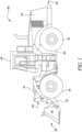
- FIG. 1 a side view of an exemplary machine 100 is illustrated.
- the machine 100 may be used for purposes, such as, construction, mining, landscaping, agriculture, and the like.
- the machine 100 is embodied as a wheel loader.
- the machine 100 may be embodied as an off highway truck, a dozer, an excavator, a tractor, a motor grader, a scraper, etc. that may be used in various industries to move, remove, or load materials, such as, asphalt, debris, dirt, snow, feed, gravel, logs, raw minerals, recycled material, rock, sand, woodchips, etc.
- the machine 100 includes a frame 102 having a front end 120 and a rear end 122 opposite to the front end 120.
- the frame 102 supports various components of the machine 100, such as a power source (not shown), thereon.
- the power source may include an engine, such as an internal combustion engine, batteries, motors, and the like.
- the power source provides power to the machine 100 for operational and mobility requirements.
- the machine 100 further includes a hood 104 proximate to the rear end 122 of the frame 102.
- the hood 104 encloses the power source therein.
- the machine 100 also includes a linkage assembly 108 movably coupled to the frame 102.
- the linkage assembly 108 is disposed proximate to the front end 120 of the machine 100.
- the linkage assembly 108 includes an arm 110 movably coupled to the frame 102.
- the machine 100 includes a work implement 112 movably coupled to the arm 110 of the linkage assembly 108.
- the work implement 112 may be used to perform one or more work operations, such as, material loading, stock piling, dumping, and the like.
- the linkage assembly 108 also includes one or more actuators 114 (only two of which are illustrated in FIG. 1 ) to effectuate a movement of the work implement 112.
- the machine 100 further includes a number of wheels 116. The wheels 116 provide support and mobility to the machine 100 on grounds.
- the machine 100 further includes an operator cabin 106 supported by the frame 102.
- the operator cabin 106 includes one or more controls (not shown), such as, joysticks, pedals, levers, buttons, switches, knobs, audio visual devices, operator consoles, a steering wheel, and the like.
- the controls may enable an operator to control the machine 100 during work operations.
- the operator of the machine 100 may sit or stand within the operator cabin 106 to perform the work operations.
- the operator cabin 106 includes a cabin light 200 (shown in FIGS. 2 to 5 ) that provides illumination within the operator cabin 106.
- the cabin light 200 may be affixed below a headliner, which in turn covers an underside of a ceiling of the operator cabin 106.
- the cabin light 200 may form a part of a cabin light assembly 150 (shown in FIG. 7 ).
- the cabin light assembly 150 includes the cabin light 200.
- the cabin light assembly 150 also includes an adapter 300 (shown in FIGS. 6 and 7 ).
- the cabin light 200 may be removably coupled with the adapter 300.
- the adapter 300 will be described in detail later in this section with reference to FIGS. 6 and 7 .
- the cabin light 200 defines a longitudinal axis "A1" and a lateral axis "A2" orthogonal to the longitudinal axis "A1".
- the cabin light 200 includes a panel 202 that couples with a light source 201 (schematically shown in FIG. 5 ).
- the cabin light 200 also includes a cover 226 and a switch 228.
- the panel 202 includes a pair of longitudinal portions 204, 205 extending along the longitudinal axis "A1" of the cabin light 200.
- Each longitudinal portion 204, 205 includes a first surface 206, a second surface 208 disposed at an offset "D1" from the first surface 206, and a first width "W1".
- the second surface 208 is spaced apart from the first surface 206 by the offset "D1".
- the first surface 206 defines a second width "W2", such that the first width "W1" is greater than the second width "W2" by a factor of at least two.
- the first width "W1" may be greater than the second width "W2" by a factor of at least 2.5, at least 3, at least 3.5, or at least 4, without any limitations. In other examples, the first width "W1" may be greater than the second width "W2" by a factor of at least 1, at least 1.5, and the like, without any limitations.
- the panel 202 further includes a first lateral portion 210 extending between the pair of longitudinal portions 204, 205 along the lateral axis "A2" of the cabin light 200.
- the first lateral portion 210 defines a first length "L1" along the longitudinal axis "A1".
- the first lateral portion 210 includes a first raised surface 212 extending along a portion of the first length "L1".
- the first raised surface 212 may have a gradually varying height. In some examples, the first raised surface 212 may extend along more than half of the first length "L1".
- the first lateral portion 210 further defines a first planar surface 214.
- the first planar surface 214 and the first raised surface 212 are disposed adjacent to each other.
- the first planar surface 214 defines a height "H1".
- the first raised surface 212 defines a maximum height "H2", such that the maximum height "H2" is greater than the height "H1".
- the panel 202 further includes a second lateral portion 216 extending between the pair of longitudinal portions 204, 205 along the lateral axis "A2" of the cabin light 200.
- the second lateral portion 216 is disposed opposite the first lateral portion 210.
- the second lateral portion 216 defines a second length "L2" along the longitudinal axis "A1".
- the second lateral portion 216 includes a second raised surface 218 extending along a portion of the second length "L2".
- the second raised surface 218 may have a gradually varying height. In some examples, the second raised surface 218 may extend along more than half of the second length "L2".
- the second lateral portion 216 further defines a second planar surface 220.
- the second planar surface 220 and the second raised surface 218 are disposed adjacent to each other.
- the second planar surface 220 defines a height "H3".
- the second raised surface 218 defines a maximum height "H4", such that the maximum height "H4" is greater than the height "H3".
- the height "H1" of the first planar surface 214 may be substantially similar to the height "H3" of the second planar surface 220.
- the maximum height "H2" of the first raised surface 212 may be substantially similar to the maximum height "H4" of the second raised surface 218.
- each of the first and second raised surfaces 212, 218 include a number of surface portions extending along the longitudinal axis "A1".
- the surface portions of the each of the first and second raised surfaces 212, 218 may be parallel to each other.
- each of the first and second raised surfaces 212, 218 includes three surface portions, without any limitations.
- the panel 202 includes an intermediate portion 230 disposed between the cover 226 and the switch 228.
- the intermediate portion 230 further includes three surface portions that are parallel to each other and extend along the longitudinal axis "A1". In some examples, each of the three surface portions of the intermediate portion 230 may be substantially planar.
- the panel 202 also includes a first side portion 221 extending orthogonally from the first lateral portion 210.
- the first side portion 221 extends along the lateral axis "A2" between the pair of longitudinal portions 204, 205.
- the panel 202 includes a first side surface 222 orthogonal to the first lateral portion 210.
- the first side surface 222 forms a part of the first side portion 221.
- the panel 202 also includes a second side portion 223 extending orthogonally from the second lateral portion 216.
- the second side portion 223 is substantially parallel to the first side portion 221.
- the second side portion 223 extends along the lateral axis "A2" between the pair of longitudinal portions 204, 205.
- the panel 202 includes a second side surface 224 orthogonal to the second lateral portion 216, such that the first side surface 222 is substantially parallel to the second side surface 224.
- the second side surface 224 forms a part of the second side portion 223.
- each of the first side surface 222 and the second side surface 224 includes a polished surface finish.
- the panel 202 includes the cover 226 fixedly coupled to the panel 202.
- the cover 226 is in alignment with the light source 201 (see FIG. 5 ), such that the cover 226 allows passage of light emitted by the light source 201 therethrough.
- the cover 226 extends between the first lateral portion 210 and the intermediate portion 230.
- the cover 226 may be made of a translucent material.
- the cover 226 defines a first side 232 extending along the lateral axis "A2" and disposed adjacent to the first raised surface 212 of the first lateral portion 210, such that the first side 232 includes a number of first linear surfaces 233. In the illustrated example of FIG. 4 , the first side 232 includes three first linear surfaces 233.
- the cover 226 further defines a second side 234 extending along the lateral axis "A2" and disposed adjacent to the intermediate portion 230, such that the second side 234 includes a number of second linear surfaces 235.
- the second side 234 includes three second linear surfaces 235.
- the cover 226 includes a first cover surface 236, a second cover surface 238, and a third cover surface 240 disposed between the first cover surface 236 and the second cover surface 238.
- Each of the first, second, and third cover surfaces 236, 238, 240 extends from the first side 232 to the second side 234. Further, each of the first cover surface 236 and the second cover surface 238 is inclined with respect to the third cover surface 240. Moreover, each of the first, second, and third cover surfaces 236, 238, 240 may be substantially planar. In some examples, the first, second, and third cover surfaces 236, 238, 240 may have a lenticular-like design, such that the cover 226 may hide/mask the hardware present behind the cover 226.
- the panel 202 further includes the switch 228 disposed between the cover 226 and the second lateral portion 216 of the panel 202. Specifically, the switch 228 is disposed between the intermediate portion 230 and the second lateral portion 216.
- the switch 228 includes a first switch surface 242, a second switch surface 244, and a third switch surface 246 extending between the first switch surface 242 and the second switch surface 244. Each of the first switch surface 242 and the second switch surface 244 is inclined with respect to the third switch surface 246. As illustrated in FIG. 4 , the first cover surface 236 is in alignment with the first switch surface 242, the second cover surface 238 is in alignment with the second switch surface 244, and the third cover surface 240 is in alignment with the third switch surface 246.
- the switch 228 may be disposed in a first state, a second state, and a third state.
- the first state of the switch 228, the light source 201 may be electrically connected with a power supply (not shown) to switch the light source 201 to an on state.
- the second state of the switch 228, the light source 201 may be electrically disconnected from the power supply to switch the light source 201 to an off state.
- the switch 228 may electrically connect the light source 201 with the power supply when a door of the operator cabin 106 (see FIG. 1 ) is open. Additionally, in the third state, the switch 228 may electrically disconnect the light source 201 from the power supply when the door of the operator cabin 106 is closed.
- the switch 228 may include one or more markings on the first switch surface 242, the second switch surface 244, and the third switch surface 246 to notify the operator regarding the operating states of the switch 228.
- the markings may be printed, protruded, embossed or engraved, without any limitations.
- the markings may be provided on the intermediate portion 230 or the second raised surface 218, without any limitations.
- the second surface 208 of each longitudinal portion 204, 205, the first lateral portion 210, the second lateral portion 216, the intermediate portion 230, and the switch 228 include a glossy surface finish.
- a low gloss treatment may be performed on the second surface 208, the first lateral portion 210, the second lateral portion 216, the intermediate portion 230, and the switch 228.
- the second surface 208, the first lateral portion 210, the second lateral portion 216, the intermediate portion 230, and the switch 228 may have a matte finish.
- the first surface 206 of each longitudinal portion 204, 205 and the cover 226 includes a polished surface finish.
- the cabin light 200 includes one or more coupling elements 248.
- the coupling elements 248 may facilitate a coupling of the cabin light 200 with the operator cabin 106 (see FIG. 1 ).
- the coupling elements 248 may facilitate a coupling of the cabin light 200 with the adapter 300 (shown in FIGS. 6 and 7 ).
- the coupling elements 248 may include any type of coupling arrangement, such as, a latch, a clamp, a magnetic lock, a snap-fit arrangement, a click fit arrangement, or mechanical fasteners, such as, bolts, screws, pins, and the like.
- the clamp may be a spring-loaded clamp.
- each coupling element 248 includes the clamp. It should be noted that the coupling elements 248 illustrated herein are exemplary in nature, and the coupling elements 248 may include any other design or size.
- the cabin light 200 further includes a back housing 250.
- the back housing 250 may hold and support the light source 201.
- the single light source 201 is schematically illustrated herein.
- a number of light sources similar to the light source 201 may be associated with the panel 202.
- the light source 201 may include any light emitting source, such as, a light emitting diode (LED) without any limitation.
- the light source 201 may emit evenly distributed light in the operator cabin 106.
- the light source 201 may be colored or may otherwise possess different lighting characteristics, as per application requirements.
- the light source 201 includes one or more electrical terminals 252 that may be electrically connected to the power supply.
- the electrical terminals 252 may establish an electrical connection between the light source 201 and the power supply.
- the cabin light 200 further includes one or more conductive elements 254 establishing an electrical connection between the one or more electrical terminals 252 and the switch 228 (see FIG. 4 ).
- the switch 228 may electrically connect the one or more electrical terminals 252 of the light source 201 with the power supply in the first state of the switch 228, and may electrically disconnect the one or more electrical terminals 252 of the light source 201 from the power supply in the second state of the switch 228. Further, in the third state of the switch 228, the switch 228 may electrically connect the one or more electrical terminals 252 of the light source 201 with the power supply when the door of the operator cabin 106 is open. Also, in the third state of the switch 228, the switch 228 may electrically disconnect the one or more electrical terminals 252 of the light source 201 from the power supply when the door of the operator cabin 106 is closed. It should be noted that the details of the connection between the switch 228, the light source 201, the power supply, etc. as explained herein are exemplary in nature, and the cabin light 200 may include any other arrangement of components, without any limitations.
- FIG. 6 a perspective view of the adapter 300 is illustrated, in accordance with an embodiment of the present disclosure.
- the adapter 300 is removably coupled with the operator cabin 106 (see FIG. 1 ).
- the adapter 300 may be used to removably couple the cabin light 200 (see FIGS. 2 to 5 ) with the operator cabin 106.
- the adapter 300 includes a first continuous surface 302 extending along an outer perimeter 316 of the adapter 300.
- the first continuous surface 302 defines two or more through-openings 304.
- the first continuous surface 302 defines three through-openings 304.
- One of the through-opening 304 is defined at a first end 306 of the adapter 300.
- two of the through-openings 304 are defined at a second end 308 of the adapter 300.
- the first continuous surface 302 may define one through-opening 304 on each of the first end 306 and the second end 308 of the adapter 300.
- the first continuous surface 302 includes a glossy surface finish. In some examples, a low gloss treatment may be performed on the first continuous surface 302. In an example, the first continuous surface 302 may have a matte finish.
- the adapter 300 further includes a second continuous surface 312 extending along an inner perimeter 318 of the adapter 300. The first continuous surface 302 is spaced apart from the second continuous surface 312. Specifically, a distance "D2" may be defined between the first continuous surface 302 and the second continuous surface 312. Further, the second continuous surface 312 includes a polished surface finish.
- the adapter 300 further defines a central opening 314 that at least partially receives the cabin light 200 based on the coupling of the cabin light 200 with the adapter 300.
- a shape of the central opening 314 may be similar to a shape of the cabin light 200.
- the central opening 314 has a rectangular shape herein. Further, in an example, a size of the central opening 314 may be lesser than a size of the cabin light 200.
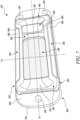
- FIG. 7 a schematic perspective view of the cabin light assembly 150 is illustrated.
- the cabin light 200 is removably coupled with the adapter 300.
- the panel 202 contacts the second continuous surface 312 (see FIG. 6 ) based on the coupling of the cabin light 200 with the adapter 300.
- the coupling elements 248 (see FIG. 5 ) of the cabin light 200 may couple with the adapter 300 in order to secure the cabin light 200 with the adapter 300.
- the coupling elements 248 may contact a surface of the adapter 300 that is opposite the second continuous surface 312 for coupling the cabin light 200 with the adapter 300.
- the cabin light 200 described herein may be aesthetically appealing.
- the glossy surface finish and the polished surface finish on various surfaces of the panel 202 may improve the aesthetics of the cabin light 200.
- the cabin light assembly 150 described herein is embodied as a modular and retrofittable light assembly that may be removably coupled with different types of operator cabins and/or different mounting arrangement in operator cabins.
- the cabin light 200 may be directly coupled to the operator cabin 106 of the machine 100, via the one or more coupling elements 248.
- the cabin light 200 may be removably coupled with the adapter 300, via the one or more coupling elements 248.
- the adapter 300 may be in turn coupled with the operator cabin 106 of the machine 100 using the mechanical fastener 310.
- the cabin light assembly 150 described herein may eliminate requirement of cabin lights having different designs and sizes, thereby reducing part numbers.
- the cabin light 200 or the adapter 300 may be quickly and easily coupled with the operator cabin 106.
Landscapes
- Engineering & Computer Science (AREA)
- Mechanical Engineering (AREA)
- General Engineering & Computer Science (AREA)
- Mining & Mineral Resources (AREA)
- Civil Engineering (AREA)
- Structural Engineering (AREA)
- Arrangements Of Lighting Devices For Vehicle Interiors, Mounting And Supporting Thereof, Circuits Therefore (AREA)
- Lighting Device Outwards From Vehicle And Optical Signal (AREA)
- Harvester Elements (AREA)
Abstract
Description
- The present disclosure relates to a cabin light and a cabin light assembly for a machine.
- A machine, such as a wheel loader, includes an operator cabin supported by a frame of the machine. The operator cabin may include one or more controls, such as, joysticks, pedals, levers, buttons, switches, knobs, audio visual devices, operator consoles, a steering wheel, and the like. The operator cabin further includes a lighting assembly to provide illumination within the operator cabin. Different types of operator cabins may have different mounting arrangements for receiving the light assembly. For example, some operator cabins may have a mounting arrangement that can be coupled with a larger sized light assembly, whereas some operator cabins may have a mounting arrangement that can be coupled with a smaller sized light assembly. It may not be feasible to manufacture light assemblies having different designs and sizes, as per the design of the operator cabin or the mounting arrangements, as such an approach may increase part numbers associated with the light assemblies. Further, conventional lighting assemblies may lack aesthetics and may not provide a modular light assembly that can be coupled with different operator cabins or mounting arrangements.
-
GB2553337A - In an aspect of the present disclosure, a cabin light for a machine is provided. The cabin light includes a panel adapted to couple with a light source. The panel includes a pair of longitudinal portions extending along a longitudinal axis of the cabin light. Each longitudinal portion includes a first surface, a second surface disposed at an offset from the first surface, and a first width. The first surface defines a second width, such that the first width is greater than the second width by a factor of at least two. The panel also includes a first lateral portion extending between the pair of longitudinal portions along a lateral axis of the cabin light. The first lateral portion defines a first length along the longitudinal axis. The first lateral portion includes a first raised surface extending along at least a portion of the first length. The panel further includes a second lateral portion extending between the pair of longitudinal portions along the lateral axis of the cabin light. The second lateral portion is disposed opposite the first lateral portion. The second lateral portion defines a second length along the longitudinal axis. The second lateral portion includes a second raised surface extending along at least a portion of the second length. The cabin light also includes a cover fixedly coupled to the panel. The cover is in alignment with the light source, such that the cover allows passage of light emitted by the light source therethrough. The cabin light further includes a switch disposed between the cover and the second lateral portion of the panel.
- In another aspect of the present disclosure, a cabin light assembly for a machine is provided. The cabin light assembly includes a cabin light including a panel adapted to couple with a light source. The panel includes a pair of longitudinal portions extending along a longitudinal axis of the cabin light. Each longitudinal portion includes a first surface, a second surface disposed at an offset from the first surface, and a first width. The first surface defines a second width, such that the first width is greater than the second width by a factor of at least two. The panel also includes a first lateral portion extending between the pair of longitudinal portions along a lateral axis of the cabin light. The first lateral portion defines a first length along the longitudinal axis. The first lateral portion includes a first raised surface extending along at least a portion of the first length. The panel further includes a second lateral portion extending between the pair of longitudinal portions along the lateral axis of the cabin light. The second lateral portion is disposed opposite the first lateral portion. The second lateral portion defines a second length along the longitudinal axis. The second lateral portion includes a second raised surface extending along at least a portion of the second length. The cabin light also includes a cover fixedly coupled to the panel. The cover is in alignment with the light source, such that the cover allows passage of light emitted by the light source therethrough. The cabin light further includes a switch disposed between the cover and the second lateral portion of the panel. The cabin light assembly also includes an adapter adapted to be removably coupled with an operator cabin of the machine. The cabin light is adapted to be removably coupled with the adapter. The adapter includes a first continuous surface extending along an outer perimeter of the adapter. The adapter also includes a second continuous surface extending along an inner perimeter of the adapter. The first continuous surface is spaced apart from the second continuous surface. The adapter defines a central opening that at least partially receives the cabin light based on a coupling of the cabin light with the adapter. The panel is adapted to contact the second continuous surface based on the coupling of the cabin light with the adapter.
- Other features and aspects of this disclosure will be apparent from the following description and the accompanying drawings.
-
-
FIG. 1 is a side view of a machine, according to an embodiment of the present disclosure; -
FIG. 2 is a perspective view of a cabin light associated with the machine ofFIG. 1 , according to an embodiment of the present disclosure; -
FIGS. 3A and 3B are side views of the cabin light ofFIG. 2 ; -
FIG. 4 is a front view of the cabin light ofFIG. 2 ; -
FIG. 5 is a rear view of the cabin light ofFIG. 2 ; -
FIG. 6 is a perspective view of an adapter of a cabin light assembly associated with the machine ofFIG. 1 , according to an embodiment of the present disclosure; and -
FIG. 7 is a perspective view illustrating the cabin light coupled to the adapter ofFIG. 6 . - Wherever possible, the same reference numbers will be used throughout the drawings to refer to the same or like parts. Referring to
FIG. 1 , a side view of anexemplary machine 100 is illustrated. Themachine 100 may be used for purposes, such as, construction, mining, landscaping, agriculture, and the like. Themachine 100 is embodied as a wheel loader. Alternatively, themachine 100 may be embodied as an off highway truck, a dozer, an excavator, a tractor, a motor grader, a scraper, etc. that may be used in various industries to move, remove, or load materials, such as, asphalt, debris, dirt, snow, feed, gravel, logs, raw minerals, recycled material, rock, sand, woodchips, etc. - The
machine 100 includes aframe 102 having afront end 120 and arear end 122 opposite to thefront end 120. Theframe 102 supports various components of themachine 100, such as a power source (not shown), thereon. The power source may include an engine, such as an internal combustion engine, batteries, motors, and the like. The power source provides power to themachine 100 for operational and mobility requirements. - The
machine 100 further includes ahood 104 proximate to therear end 122 of theframe 102. Thehood 104 encloses the power source therein. Themachine 100 also includes alinkage assembly 108 movably coupled to theframe 102. Thelinkage assembly 108 is disposed proximate to thefront end 120 of themachine 100. Thelinkage assembly 108 includes anarm 110 movably coupled to theframe 102. Further, themachine 100 includes a work implement 112 movably coupled to thearm 110 of thelinkage assembly 108. The work implement 112 may be used to perform one or more work operations, such as, material loading, stock piling, dumping, and the like. Thelinkage assembly 108 also includes one or more actuators 114 (only two of which are illustrated inFIG. 1 ) to effectuate a movement of the work implement 112. Themachine 100 further includes a number ofwheels 116. Thewheels 116 provide support and mobility to themachine 100 on grounds. - The
machine 100 further includes anoperator cabin 106 supported by theframe 102. Theoperator cabin 106 includes one or more controls (not shown), such as, joysticks, pedals, levers, buttons, switches, knobs, audio visual devices, operator consoles, a steering wheel, and the like. The controls may enable an operator to control themachine 100 during work operations. The operator of themachine 100 may sit or stand within theoperator cabin 106 to perform the work operations. Further, theoperator cabin 106 includes a cabin light 200 (shown inFIGS. 2 to 5 ) that provides illumination within theoperator cabin 106. Thecabin light 200 may be affixed below a headliner, which in turn covers an underside of a ceiling of theoperator cabin 106. In some examples, thecabin light 200 may form a part of a cabin light assembly 150 (shown inFIG. 7 ). Specifically, the cabinlight assembly 150 includes thecabin light 200. The cabinlight assembly 150 also includes an adapter 300 (shown inFIGS. 6 and7 ). Thecabin light 200 may be removably coupled with theadapter 300. Theadapter 300 will be described in detail later in this section with reference toFIGS. 6 and7 . - Referring to
FIG. 2 , a perspective view of thecabin light 200 associated with themachine 100 is illustrated, in accordance with an embodiment of the present disclosure. Thecabin light 200 defines a longitudinal axis "A1" and a lateral axis "A2" orthogonal to the longitudinal axis "A1". Thecabin light 200 includes apanel 202 that couples with a light source 201 (schematically shown inFIG. 5 ). Thecabin light 200 also includes acover 226 and aswitch 228. - Further, the
panel 202 includes a pair oflongitudinal portions cabin light 200. Eachlongitudinal portion first surface 206, asecond surface 208 disposed at an offset "D1" from thefirst surface 206, and a first width "W1". In other words, thesecond surface 208 is spaced apart from thefirst surface 206 by the offset "D1". Further, thefirst surface 206 defines a second width "W2", such that the first width "W1" is greater than the second width "W2" by a factor of at least two. However, in some examples, the first width "W1" may be greater than the second width "W2" by a factor of at least 2.5, at least 3, at least 3.5, or at least 4, without any limitations. In other examples, the first width "W1" may be greater than the second width "W2" by a factor of at least 1, at least 1.5, and the like, without any limitations. - The
panel 202 further includes a firstlateral portion 210 extending between the pair oflongitudinal portions cabin light 200. The firstlateral portion 210 defines a first length "L1" along the longitudinal axis "A1". Further, the firstlateral portion 210 includes a first raisedsurface 212 extending along a portion of the first length "L1". The first raisedsurface 212 may have a gradually varying height. In some examples, the first raisedsurface 212 may extend along more than half of the first length "L1". The firstlateral portion 210 further defines a firstplanar surface 214. The firstplanar surface 214 and the first raisedsurface 212 are disposed adjacent to each other. The firstplanar surface 214 defines a height "H1". Further, the first raisedsurface 212 defines a maximum height "H2", such that the maximum height "H2" is greater than the height "H1". - The
panel 202 further includes a secondlateral portion 216 extending between the pair oflongitudinal portions cabin light 200. The secondlateral portion 216 is disposed opposite the firstlateral portion 210. The secondlateral portion 216 defines a second length "L2" along the longitudinal axis "A1". The secondlateral portion 216 includes a second raisedsurface 218 extending along a portion of the second length "L2". The second raisedsurface 218 may have a gradually varying height. In some examples, the second raisedsurface 218 may extend along more than half of the second length "L2". The secondlateral portion 216 further defines a secondplanar surface 220. The secondplanar surface 220 and the second raisedsurface 218 are disposed adjacent to each other. The secondplanar surface 220 defines a height "H3". Further, the second raisedsurface 218 defines a maximum height "H4", such that the maximum height "H4" is greater than the height "H3". In some examples, the height "H1" of the firstplanar surface 214 may be substantially similar to the height "H3" of the secondplanar surface 220. In some examples, the maximum height "H2" of the first raisedsurface 212 may be substantially similar to the maximum height "H4" of the second raisedsurface 218. - Further, each of the first and second raised
surfaces surfaces FIG. 2 , each of the first and second raisedsurfaces - Further, the
panel 202 includes anintermediate portion 230 disposed between thecover 226 and theswitch 228. Theintermediate portion 230 further includes three surface portions that are parallel to each other and extend along the longitudinal axis "A1". In some examples, each of the three surface portions of theintermediate portion 230 may be substantially planar. - Referring to
FIG. 3A , thepanel 202 also includes afirst side portion 221 extending orthogonally from the firstlateral portion 210. Thefirst side portion 221 extends along the lateral axis "A2" between the pair oflongitudinal portions panel 202 includes afirst side surface 222 orthogonal to the firstlateral portion 210. Thefirst side surface 222 forms a part of thefirst side portion 221. - Referring now to
FIG. 3B , thepanel 202 also includes asecond side portion 223 extending orthogonally from the secondlateral portion 216. Thesecond side portion 223 is substantially parallel to thefirst side portion 221. Thesecond side portion 223 extends along the lateral axis "A2" between the pair oflongitudinal portions panel 202 includes asecond side surface 224 orthogonal to the secondlateral portion 216, such that thefirst side surface 222 is substantially parallel to thesecond side surface 224. Thesecond side surface 224 forms a part of thesecond side portion 223. Further, each of thefirst side surface 222 and thesecond side surface 224 includes a polished surface finish. - Referring now to
FIG. 4 , thepanel 202 includes thecover 226 fixedly coupled to thepanel 202. Thecover 226 is in alignment with the light source 201 (seeFIG. 5 ), such that thecover 226 allows passage of light emitted by thelight source 201 therethrough. Thecover 226 extends between the firstlateral portion 210 and theintermediate portion 230. In some examples, thecover 226 may be made of a translucent material. Thecover 226 defines afirst side 232 extending along the lateral axis "A2" and disposed adjacent to the first raisedsurface 212 of the firstlateral portion 210, such that thefirst side 232 includes a number of firstlinear surfaces 233. In the illustrated example ofFIG. 4 , thefirst side 232 includes three firstlinear surfaces 233. Thecover 226 further defines asecond side 234 extending along the lateral axis "A2" and disposed adjacent to theintermediate portion 230, such that thesecond side 234 includes a number of secondlinear surfaces 235. In the illustrated example ofFIG. 4 , thesecond side 234 includes three secondlinear surfaces 235. - Further, the
cover 226 includes afirst cover surface 236, asecond cover surface 238, and athird cover surface 240 disposed between thefirst cover surface 236 and thesecond cover surface 238. Each of the first, second, and third cover surfaces 236, 238, 240 extends from thefirst side 232 to thesecond side 234. Further, each of thefirst cover surface 236 and thesecond cover surface 238 is inclined with respect to thethird cover surface 240. Moreover, each of the first, second, and third cover surfaces 236, 238, 240 may be substantially planar. In some examples, the first, second, and third cover surfaces 236, 238, 240 may have a lenticular-like design, such that thecover 226 may hide/mask the hardware present behind thecover 226. - The
panel 202 further includes theswitch 228 disposed between thecover 226 and the secondlateral portion 216 of thepanel 202. Specifically, theswitch 228 is disposed between theintermediate portion 230 and the secondlateral portion 216. Theswitch 228 includes afirst switch surface 242, asecond switch surface 244, and athird switch surface 246 extending between thefirst switch surface 242 and thesecond switch surface 244. Each of thefirst switch surface 242 and thesecond switch surface 244 is inclined with respect to thethird switch surface 246. As illustrated inFIG. 4 , thefirst cover surface 236 is in alignment with thefirst switch surface 242, thesecond cover surface 238 is in alignment with thesecond switch surface 244, and thethird cover surface 240 is in alignment with thethird switch surface 246. - Further, the
switch 228 may be disposed in a first state, a second state, and a third state. In the first state of theswitch 228, thelight source 201 may be electrically connected with a power supply (not shown) to switch thelight source 201 to an on state. In the second state of theswitch 228, thelight source 201 may be electrically disconnected from the power supply to switch thelight source 201 to an off state. Further, in the third state of theswitch 228, theswitch 228 may electrically connect thelight source 201 with the power supply when a door of the operator cabin 106 (seeFIG. 1 ) is open. Additionally, in the third state, theswitch 228 may electrically disconnect thelight source 201 from the power supply when the door of theoperator cabin 106 is closed. In some examples, theswitch 228 may include one or more markings on thefirst switch surface 242, thesecond switch surface 244, and thethird switch surface 246 to notify the operator regarding the operating states of theswitch 228. The markings may be printed, protruded, embossed or engraved, without any limitations. Alternatively, the markings may be provided on theintermediate portion 230 or the second raisedsurface 218, without any limitations. - Further, in some examples, the
second surface 208 of eachlongitudinal portion lateral portion 210, the secondlateral portion 216, theintermediate portion 230, and theswitch 228 include a glossy surface finish. In some examples, a low gloss treatment may be performed on thesecond surface 208, the firstlateral portion 210, the secondlateral portion 216, theintermediate portion 230, and theswitch 228. In an example, thesecond surface 208, the firstlateral portion 210, the secondlateral portion 216, theintermediate portion 230, and theswitch 228 may have a matte finish. Moreover, in some examples, thefirst surface 206 of eachlongitudinal portion cover 226 includes a polished surface finish. - Referring to
FIG. 5 , a schematic rear view of thecabin light 200 is illustrated. As illustrated inFIG. 5 , thecabin light 200 includes one ormore coupling elements 248. Thecoupling elements 248 may facilitate a coupling of thecabin light 200 with the operator cabin 106 (seeFIG. 1 ). In another example, thecoupling elements 248 may facilitate a coupling of thecabin light 200 with the adapter 300 (shown inFIGS. 6 and7 ). Thecoupling elements 248 may include any type of coupling arrangement, such as, a latch, a clamp, a magnetic lock, a snap-fit arrangement, a click fit arrangement, or mechanical fasteners, such as, bolts, screws, pins, and the like. In an example, the clamp may be a spring-loaded clamp. In the illustrated example ofFIG. 5 , eachcoupling element 248 includes the clamp. It should be noted that thecoupling elements 248 illustrated herein are exemplary in nature, and thecoupling elements 248 may include any other design or size. - The
cabin light 200 further includes aback housing 250. Theback housing 250 may hold and support thelight source 201. For exemplary purposes, the singlelight source 201 is schematically illustrated herein. Alternatively, a number of light sources similar to thelight source 201 may be associated with thepanel 202. It should be noted that thelight source 201 may include any light emitting source, such as, a light emitting diode (LED) without any limitation. Further, thelight source 201 may emit evenly distributed light in theoperator cabin 106. Thelight source 201 may be colored or may otherwise possess different lighting characteristics, as per application requirements. - The
light source 201 includes one or moreelectrical terminals 252 that may be electrically connected to the power supply. Theelectrical terminals 252 may establish an electrical connection between thelight source 201 and the power supply. Thecabin light 200 further includes one or moreconductive elements 254 establishing an electrical connection between the one or moreelectrical terminals 252 and the switch 228 (seeFIG. 4 ). - The
switch 228 may electrically connect the one or moreelectrical terminals 252 of thelight source 201 with the power supply in the first state of theswitch 228, and may electrically disconnect the one or moreelectrical terminals 252 of thelight source 201 from the power supply in the second state of theswitch 228. Further, in the third state of theswitch 228, theswitch 228 may electrically connect the one or moreelectrical terminals 252 of thelight source 201 with the power supply when the door of theoperator cabin 106 is open. Also, in the third state of theswitch 228, theswitch 228 may electrically disconnect the one or moreelectrical terminals 252 of thelight source 201 from the power supply when the door of theoperator cabin 106 is closed. It should be noted that the details of the connection between theswitch 228, thelight source 201, the power supply, etc. as explained herein are exemplary in nature, and thecabin light 200 may include any other arrangement of components, without any limitations. - Referring to
FIG. 6 , a perspective view of theadapter 300 is illustrated, in accordance with an embodiment of the present disclosure. Theadapter 300 is removably coupled with the operator cabin 106 (seeFIG. 1 ). Theadapter 300 may be used to removably couple the cabin light 200 (seeFIGS. 2 to 5 ) with theoperator cabin 106. As illustrated inFIG. 6 , theadapter 300 includes a firstcontinuous surface 302 extending along anouter perimeter 316 of theadapter 300. The firstcontinuous surface 302 defines two or more through-openings 304. In the illustrated example ofFIG. 6 , the firstcontinuous surface 302 defines three through-openings 304. One of the through-opening 304 is defined at afirst end 306 of theadapter 300. Further, two of the through-openings 304 are defined at asecond end 308 of theadapter 300. However, in other examples, the firstcontinuous surface 302 may define one through-opening 304 on each of thefirst end 306 and thesecond end 308 of theadapter 300. - Each of the two or more through-
openings 304 receive a correspondingmechanical fastener 310 for removably coupling theadapter 300 with theoperator cabin 106 of themachine 100. Further, the firstcontinuous surface 302 includes a glossy surface finish. In some examples, a low gloss treatment may be performed on the firstcontinuous surface 302. In an example, the firstcontinuous surface 302 may have a matte finish. Theadapter 300 further includes a secondcontinuous surface 312 extending along aninner perimeter 318 of theadapter 300. The firstcontinuous surface 302 is spaced apart from the secondcontinuous surface 312. Specifically, a distance "D2" may be defined between the firstcontinuous surface 302 and the secondcontinuous surface 312. Further, the secondcontinuous surface 312 includes a polished surface finish. - The
adapter 300 further defines acentral opening 314 that at least partially receives thecabin light 200 based on the coupling of thecabin light 200 with theadapter 300. Generally, a shape of thecentral opening 314 may be similar to a shape of thecabin light 200. Thecentral opening 314 has a rectangular shape herein. Further, in an example, a size of thecentral opening 314 may be lesser than a size of thecabin light 200. - Referring to
FIG. 7 , a schematic perspective view of the cabinlight assembly 150 is illustrated. As illustrated, thecabin light 200 is removably coupled with theadapter 300. Further, thepanel 202 contacts the second continuous surface 312 (seeFIG. 6 ) based on the coupling of thecabin light 200 with theadapter 300. Furthermore, the coupling elements 248 (seeFIG. 5 ) of thecabin light 200 may couple with theadapter 300 in order to secure thecabin light 200 with theadapter 300. In some examples, thecoupling elements 248 may contact a surface of theadapter 300 that is opposite the secondcontinuous surface 312 for coupling thecabin light 200 with theadapter 300. - The
cabin light 200 described herein may be aesthetically appealing. For example, the glossy surface finish and the polished surface finish on various surfaces of thepanel 202 may improve the aesthetics of thecabin light 200. Further, the cabinlight assembly 150 described herein is embodied as a modular and retrofittable light assembly that may be removably coupled with different types of operator cabins and/or different mounting arrangement in operator cabins. - In some examples, the
cabin light 200 may be directly coupled to theoperator cabin 106 of themachine 100, via the one ormore coupling elements 248. In other examples, thecabin light 200 may be removably coupled with theadapter 300, via the one ormore coupling elements 248. Theadapter 300 may be in turn coupled with theoperator cabin 106 of themachine 100 using themechanical fastener 310. Thus, the cabinlight assembly 150 described herein may eliminate requirement of cabin lights having different designs and sizes, thereby reducing part numbers. Further, thecabin light 200 or theadapter 300 may be quickly and easily coupled with theoperator cabin 106. - While aspects of the present disclosure have been particularly shown and described with reference to the embodiments above, it will be understood by those skilled in the art that various additional embodiments may be contemplated by the modification of the disclosed machines, systems and methods without departing from the spirit and scope of the disclosure. Such embodiments should be understood to fall within the scope of the present disclosure as determined based upon the claims and any equivalents thereof.
Claims (10)
- A cabin light (200) for a machine (100), the cabin light (200) comprising:a panel (202) adapted to couple with a light source (201), the panel (202) including:a pair of longitudinal portions (204, 205) extending along a longitudinal axis (A1) of the cabin light (200), each longitudinal portion (204, 205) including a first surface (206), a second surface (208) disposed at an offset (D1) from the first surface (206), and a first width (W1), wherein the first surface (206) defines a second width (W2), such that the first width (W1) is greater than the second width (W2) by a factor of at least two;a first lateral portion (210) extending between the pair of longitudinal portions (204, 205) along a lateral axis (A2) of the cabin light (200), the first lateral portion (210) defining a first length (L1) along the longitudinal axis (A1), wherein the first lateral portion (210) includes a first raised surface (212) extending along at least a portion of the first length (L1); anda second lateral portion (216) extending between the pair of longitudinal portions (204, 205) along the lateral axis (A2) of the cabin light (200), the second lateral portion (216) being disposed opposite the first lateral portion (210), the second lateral portion (216) defining a second length (L2) along the longitudinal axis (A1), wherein the second lateral portion (216) includes a second raised surface (218) extending along at least a portion of the second length (L2);a cover (226) fixedly coupled to the panel (202), wherein the cover (226) is in alignment with the light source (201), such that the cover (226) allows passage of light emitted by the light source (201) therethrough; anda switch (228) disposed between the cover (226) and the second lateral portion (216) of the panel (202).
- The cabin light (200) of claim 1, wherein the panel (202) further includes an intermediate portion (230) disposed between the cover (226) and the switch (228).
- The cabin light (200) of claim 2, wherein the cover (226) extends between the first lateral portion (210) and the intermediate portion (230), the cover (226) defining a first side (232) extending along the lateral axis (A2) and disposed adjacent to the first raised surface (212) of the first lateral portion (210), such that the first side (232) includes a plurality of first linear surfaces (233), the cover (226) further defining a second side (234) extending along the lateral axis (A2) and disposed adjacent to the intermediate portion (230), such that the second side (234) includes a plurality of second linear surfaces (235).
- The cabin light (200) of claim 3, wherein the cover (226) includes a first cover surface (236), a second cover surface (238), and a third cover surface (240) disposed between the first cover surface (236) and the second cover surface (238), each of the first, second, and third cover surfaces (236, 238, 240) extending from the first side (232) to the second side (234), each of the first cover surface (236) and the second cover surface (238) being inclined with respect to the third cover surface (240).
- The cabin light (200) of claim 2, wherein the second surface (208) of each longitudinal portion (204, 205), the first lateral portion (210), the second lateral portion (216), the intermediate portion (230), and the switch (228) include a glossy surface finish.
- The cabin light (200) of claim 1, wherein the first surface (206) of each longitudinal portion (204, 205) and the cover (226) includes a polished surface finish.
- The cabin light (200) of claim 1, wherein the switch (228) includes a first switch surface (242), a second switch surface (244), and a third switch surface (246) extending between the first switch surface (242) and the second switch surface (244), each of the first switch surface (242) and the second switch surface (244) being inclined with respect to the third switch surface (246).
- The cabin light (200) of claim 1, wherein the panel (202) further includes a first side surface (222) orthogonal to the first lateral portion (210), wherein the panel (202) further includes a second side surface (224) orthogonal to the second lateral portion (216), such that the first side surface (222) is substantially parallel to the second side surface (224), and wherein each of the first side surface (222) and the second side surface (224) includes a polished surface finish.
- The cabin light (200) of claim 1, wherein the cabin light (200) is adapted to be removably coupled with an adapter (300), and wherein the adapter (300) is adapted to be removably coupled with an operator cabin (106) of the machine (100), the adapter (300) including:a first continuous surface (302) extending along an outer perimeter (316) of the adapter (300); anda second continuous surface (312) extending along an inner perimeter (318) of the adapter (300), the first continuous surface (302) being spaced apart from the second continuous surface (312), the adapter (300) defining a central opening (314) that at least partially receives the cabin light (200) based on a coupling of the cabin light (200) with the adapter (300), wherein the panel (202) is adapted to contact the second continuous surface (312) based on the coupling of the cabin light (200) with the adapter (300).
- The cabin light (200) of claim 9, wherein the first continuous surface (302) defines at least two through-openings (304), and wherein each of the at least two through-openings (304) receives a corresponding mechanical fastener (310) for removably coupling the adapter (300) with the operator cabin (106) of the machine (100).
Applications Claiming Priority (1)
| Application Number | Priority Date | Filing Date | Title |
|---|---|---|---|
| US17/654,636 US11904768B2 (en) | 2022-03-14 | 2022-03-14 | Cabin light and cabin light assembly for machine |
Publications (1)
| Publication Number | Publication Date |
|---|---|
| EP4245608A1 true EP4245608A1 (en) | 2023-09-20 |
Family
ID=85321092
Family Applications (1)
| Application Number | Title | Priority Date | Filing Date |
|---|---|---|---|
| EP23157659.6A Withdrawn EP4245608A1 (en) | 2022-03-14 | 2023-02-21 | Cabin light for a machine |
Country Status (4)
| Country | Link |
|---|---|
| US (1) | US11904768B2 (en) |
| EP (1) | EP4245608A1 (en) |
| CN (1) | CN116753485A (en) |
| AU (1) | AU2023201065A1 (en) |
Families Citing this family (1)
| Publication number | Priority date | Publication date | Assignee | Title |
|---|---|---|---|---|
| USD1035932S1 (en) * | 2022-03-14 | 2024-07-16 | Caterpillar Inc. | Cabin light for machine |
Citations (5)
| Publication number | Priority date | Publication date | Assignee | Title |
|---|---|---|---|---|
| US20100127525A1 (en) * | 2007-03-15 | 2010-05-27 | Johnson Controls Technology Company | Overhead console |
| JP4930220B2 (en) * | 2007-06-27 | 2012-05-16 | トヨタ紡織株式会社 | Switch structure |
| JP5130118B2 (en) * | 2007-09-14 | 2013-01-30 | 矢崎総業株式会社 | Car interior lighting system |
| US20150353005A1 (en) * | 2013-01-11 | 2015-12-10 | Yanfeng Global Automotive Interior Systems Co., Ltd | Thin overhead console |
| GB2553337A (en) | 2016-09-02 | 2018-03-07 | Daimler Ag | Dome light assembly for a vehicle, cabin for a vehicle comprising a dome light assembly, and vehicle comprising a cabin with a dome light assembly |
Family Cites Families (9)
| Publication number | Priority date | Publication date | Assignee | Title |
|---|---|---|---|---|
| USD315216S (en) * | 1987-12-11 | 1991-03-05 | Progressive Dynamic, Inc. | Recreational vehicle interior light fixture |
| US4930056A (en) * | 1989-05-30 | 1990-05-29 | Progressive Dynamics, Inc. | Snap-on frame for light fixtures |
| US5003449A (en) * | 1990-03-22 | 1991-03-26 | Progressive Dynamics, Inc. | Light fixture with secondary reflector |
| JP3877192B2 (en) * | 1997-10-24 | 2007-02-07 | 第一電装部品株式会社 | Vehicle interior light |
| JP2005185056A (en) * | 2003-12-22 | 2005-07-07 | T An T:Kk | Bus bar board for vehicular room lamp |
| JP4260064B2 (en) * | 2004-05-21 | 2009-04-30 | 矢崎総業株式会社 | Interior lighting for vehicles |
| JP5806477B2 (en) * | 2011-02-16 | 2015-11-10 | 矢崎総業株式会社 | Interior lighting for vehicles |
| EP3573043A3 (en) * | 2019-07-19 | 2019-12-04 | WEIDPLAS GmbH | Component comprising a base part, additional part and a varnish covering layer and method for producing such a component |
| CN213901016U (en) * | 2020-12-18 | 2021-08-06 | 丹阳市光华汽车内饰件有限公司 | Inner ceiling lamp with sterilization and disinfection functions |
-
2022
- 2022-03-14 US US17/654,636 patent/US11904768B2/en active Active
-
2023
- 2023-02-21 EP EP23157659.6A patent/EP4245608A1/en not_active Withdrawn
- 2023-02-23 AU AU2023201065A patent/AU2023201065A1/en active Pending
- 2023-03-13 CN CN202310265520.4A patent/CN116753485A/en active Pending
Patent Citations (5)
| Publication number | Priority date | Publication date | Assignee | Title |
|---|---|---|---|---|
| US20100127525A1 (en) * | 2007-03-15 | 2010-05-27 | Johnson Controls Technology Company | Overhead console |
| JP4930220B2 (en) * | 2007-06-27 | 2012-05-16 | トヨタ紡織株式会社 | Switch structure |
| JP5130118B2 (en) * | 2007-09-14 | 2013-01-30 | 矢崎総業株式会社 | Car interior lighting system |
| US20150353005A1 (en) * | 2013-01-11 | 2015-12-10 | Yanfeng Global Automotive Interior Systems Co., Ltd | Thin overhead console |
| GB2553337A (en) | 2016-09-02 | 2018-03-07 | Daimler Ag | Dome light assembly for a vehicle, cabin for a vehicle comprising a dome light assembly, and vehicle comprising a cabin with a dome light assembly |
Also Published As
| Publication number | Publication date |
|---|---|
| AU2023201065A1 (en) | 2023-09-28 |
| US20230286434A1 (en) | 2023-09-14 |
| CN116753485A (en) | 2023-09-15 |
| US11904768B2 (en) | 2024-02-20 |
Similar Documents
| Publication | Publication Date | Title |
|---|---|---|
| US9670939B2 (en) | Operation control system | |
| EP2189328B1 (en) | Vehicle command armrest assembly | |
| US11518450B2 (en) | Loader cab | |
| JP7213045B2 (en) | Work vehicle and vehicle charging system | |
| JP3573656B2 (en) | Working unit structure of work machine | |
| US11904768B2 (en) | Cabin light and cabin light assembly for machine | |
| KR102652954B1 (en) | construction machinery | |
| US11801794B2 (en) | Display position for cab with overhead door | |
| JP5319617B2 (en) | Work vehicle lever dustproof structure | |
| US11047110B2 (en) | Hydraulic sub-assembly for a power machine | |
| US12129630B2 (en) | Installation structure of electric component and hydraulic hose for working machine | |
| US9855976B2 (en) | Actuation system for hood of a machine | |
| JP2001026947A (en) | Construction vehicle front console | |
| JP4271357B2 (en) | Traveling vehicle | |
| JP7552480B2 (en) | Construction Machinery | |
| JP4330779B2 (en) | Arrangement structure of control electrical parts in work vehicle | |
| KR20110072606A (en) | Switchgear for construction machinery | |
| JPH0529258Y2 (en) | ||
| JP2000118980A (en) | Industrial vehicle | |
| JP2022159060A (en) | Working vehicle | |
| JP2002146838A (en) | Console device for construction equipment | |
| JPH07292726A (en) | Pedal device of construction machine | |
| JPH10183697A (en) | Work machine panel structure | |
| JP2003293395A (en) | Headlight device of construction machinery | |
| JPH08129934A (en) | Armrest installed type front loader operating lever |
Legal Events
| Date | Code | Title | Description |
|---|---|---|---|
| PUAI | Public reference made under article 153(3) epc to a published international application that has entered the european phase |
Free format text: ORIGINAL CODE: 0009012 |
|
| STAA | Information on the status of an ep patent application or granted ep patent |
Free format text: STATUS: THE APPLICATION HAS BEEN PUBLISHED |
|
| AK | Designated contracting states |
Kind code of ref document: A1 Designated state(s): AL AT BE BG CH CY CZ DE DK EE ES FI FR GB GR HR HU IE IS IT LI LT LU LV MC ME MK MT NL NO PL PT RO RS SE SI SK SM TR |
|
| STAA | Information on the status of an ep patent application or granted ep patent |
Free format text: STATUS: REQUEST FOR EXAMINATION WAS MADE |
|
| 17P | Request for examination filed |
Effective date: 20231204 |
|
| RBV | Designated contracting states (corrected) |
Designated state(s): AL AT BE BG CH CY CZ DE DK EE ES FI FR GB GR HR HU IE IS IT LI LT LU LV MC ME MK MT NL NO PL PT RO RS SE SI SK SM TR |
|
| GRAP | Despatch of communication of intention to grant a patent |
Free format text: ORIGINAL CODE: EPIDOSNIGR1 |
|
| STAA | Information on the status of an ep patent application or granted ep patent |
Free format text: STATUS: GRANT OF PATENT IS INTENDED |
|
| INTG | Intention to grant announced |
Effective date: 20241004 |
|
| STAA | Information on the status of an ep patent application or granted ep patent |
Free format text: STATUS: THE APPLICATION IS DEEMED TO BE WITHDRAWN |
|
| 18D | Application deemed to be withdrawn |
Effective date: 20250205 |