EP4245497A1 - Compression mold, resin molding device, resin molding system, and method for manufacturing resin molded product - Google Patents
Compression mold, resin molding device, resin molding system, and method for manufacturing resin molded product Download PDFInfo
- Publication number
- EP4245497A1 EP4245497A1 EP21891480.2A EP21891480A EP4245497A1 EP 4245497 A1 EP4245497 A1 EP 4245497A1 EP 21891480 A EP21891480 A EP 21891480A EP 4245497 A1 EP4245497 A1 EP 4245497A1
- Authority
- EP
- European Patent Office
- Prior art keywords
- resin
- surface member
- mold
- resin molding
- molding apparatus
- Prior art date
- Legal status (The legal status is an assumption and is not a legal conclusion. Google has not performed a legal analysis and makes no representation as to the accuracy of the status listed.)
- Pending
Links
Images



Classifications
-
- B—PERFORMING OPERATIONS; TRANSPORTING
- B29—WORKING OF PLASTICS; WORKING OF SUBSTANCES IN A PLASTIC STATE IN GENERAL
- B29C—SHAPING OR JOINING OF PLASTICS; SHAPING OF MATERIAL IN A PLASTIC STATE, NOT OTHERWISE PROVIDED FOR; AFTER-TREATMENT OF THE SHAPED PRODUCTS, e.g. REPAIRING
- B29C43/00—Compression moulding, i.e. applying external pressure to flow the moulding material; Apparatus therefor
- B29C43/32—Component parts, details or accessories; Auxiliary operations
- B29C43/36—Moulds for making articles of definite length, i.e. discrete articles
-
- B—PERFORMING OPERATIONS; TRANSPORTING
- B29—WORKING OF PLASTICS; WORKING OF SUBSTANCES IN A PLASTIC STATE IN GENERAL
- B29C—SHAPING OR JOINING OF PLASTICS; SHAPING OF MATERIAL IN A PLASTIC STATE, NOT OTHERWISE PROVIDED FOR; AFTER-TREATMENT OF THE SHAPED PRODUCTS, e.g. REPAIRING
- B29C43/00—Compression moulding, i.e. applying external pressure to flow the moulding material; Apparatus therefor
- B29C43/02—Compression moulding, i.e. applying external pressure to flow the moulding material; Apparatus therefor of articles of definite length, i.e. discrete articles
- B29C43/04—Compression moulding, i.e. applying external pressure to flow the moulding material; Apparatus therefor of articles of definite length, i.e. discrete articles using movable moulds
-
- B—PERFORMING OPERATIONS; TRANSPORTING
- B29—WORKING OF PLASTICS; WORKING OF SUBSTANCES IN A PLASTIC STATE IN GENERAL
- B29C—SHAPING OR JOINING OF PLASTICS; SHAPING OF MATERIAL IN A PLASTIC STATE, NOT OTHERWISE PROVIDED FOR; AFTER-TREATMENT OF THE SHAPED PRODUCTS, e.g. REPAIRING
- B29C33/00—Moulds or cores; Details thereof or accessories therefor
- B29C33/0038—Moulds or cores; Details thereof or accessories therefor with sealing means or the like
-
- B—PERFORMING OPERATIONS; TRANSPORTING
- B29—WORKING OF PLASTICS; WORKING OF SUBSTANCES IN A PLASTIC STATE IN GENERAL
- B29C—SHAPING OR JOINING OF PLASTICS; SHAPING OF MATERIAL IN A PLASTIC STATE, NOT OTHERWISE PROVIDED FOR; AFTER-TREATMENT OF THE SHAPED PRODUCTS, e.g. REPAIRING
- B29C33/00—Moulds or cores; Details thereof or accessories therefor
- B29C33/12—Moulds or cores; Details thereof or accessories therefor with incorporated means for positioning inserts, e.g. labels
-
- B—PERFORMING OPERATIONS; TRANSPORTING
- B29—WORKING OF PLASTICS; WORKING OF SUBSTANCES IN A PLASTIC STATE IN GENERAL
- B29C—SHAPING OR JOINING OF PLASTICS; SHAPING OF MATERIAL IN A PLASTIC STATE, NOT OTHERWISE PROVIDED FOR; AFTER-TREATMENT OF THE SHAPED PRODUCTS, e.g. REPAIRING
- B29C43/00—Compression moulding, i.e. applying external pressure to flow the moulding material; Apparatus therefor
- B29C43/02—Compression moulding, i.e. applying external pressure to flow the moulding material; Apparatus therefor of articles of definite length, i.e. discrete articles
- B29C43/18—Compression moulding, i.e. applying external pressure to flow the moulding material; Apparatus therefor of articles of definite length, i.e. discrete articles incorporating preformed parts or layers, e.g. compression moulding around inserts or for coating articles
-
- B—PERFORMING OPERATIONS; TRANSPORTING
- B29—WORKING OF PLASTICS; WORKING OF SUBSTANCES IN A PLASTIC STATE IN GENERAL
- B29C—SHAPING OR JOINING OF PLASTICS; SHAPING OF MATERIAL IN A PLASTIC STATE, NOT OTHERWISE PROVIDED FOR; AFTER-TREATMENT OF THE SHAPED PRODUCTS, e.g. REPAIRING
- B29C43/00—Compression moulding, i.e. applying external pressure to flow the moulding material; Apparatus therefor
- B29C43/32—Component parts, details or accessories; Auxiliary operations
- B29C43/34—Feeding the material to the mould or the compression means
-
- B—PERFORMING OPERATIONS; TRANSPORTING
- B29—WORKING OF PLASTICS; WORKING OF SUBSTANCES IN A PLASTIC STATE IN GENERAL
- B29C—SHAPING OR JOINING OF PLASTICS; SHAPING OF MATERIAL IN A PLASTIC STATE, NOT OTHERWISE PROVIDED FOR; AFTER-TREATMENT OF THE SHAPED PRODUCTS, e.g. REPAIRING
- B29C43/00—Compression moulding, i.e. applying external pressure to flow the moulding material; Apparatus therefor
- B29C43/32—Component parts, details or accessories; Auxiliary operations
- B29C43/36—Moulds for making articles of definite length, i.e. discrete articles
- B29C43/3607—Moulds for making articles of definite length, i.e. discrete articles with sealing means or the like
-
- B—PERFORMING OPERATIONS; TRANSPORTING
- B29—WORKING OF PLASTICS; WORKING OF SUBSTANCES IN A PLASTIC STATE IN GENERAL
- B29C—SHAPING OR JOINING OF PLASTICS; SHAPING OF MATERIAL IN A PLASTIC STATE, NOT OTHERWISE PROVIDED FOR; AFTER-TREATMENT OF THE SHAPED PRODUCTS, e.g. REPAIRING
- B29C43/00—Compression moulding, i.e. applying external pressure to flow the moulding material; Apparatus therefor
- B29C43/02—Compression moulding, i.e. applying external pressure to flow the moulding material; Apparatus therefor of articles of definite length, i.e. discrete articles
- B29C43/18—Compression moulding, i.e. applying external pressure to flow the moulding material; Apparatus therefor of articles of definite length, i.e. discrete articles incorporating preformed parts or layers, e.g. compression moulding around inserts or for coating articles
- B29C2043/181—Compression moulding, i.e. applying external pressure to flow the moulding material; Apparatus therefor of articles of definite length, i.e. discrete articles incorporating preformed parts or layers, e.g. compression moulding around inserts or for coating articles encapsulated
-
- B—PERFORMING OPERATIONS; TRANSPORTING
- B29—WORKING OF PLASTICS; WORKING OF SUBSTANCES IN A PLASTIC STATE IN GENERAL
- B29C—SHAPING OR JOINING OF PLASTICS; SHAPING OF MATERIAL IN A PLASTIC STATE, NOT OTHERWISE PROVIDED FOR; AFTER-TREATMENT OF THE SHAPED PRODUCTS, e.g. REPAIRING
- B29C43/00—Compression moulding, i.e. applying external pressure to flow the moulding material; Apparatus therefor
- B29C43/32—Component parts, details or accessories; Auxiliary operations
- B29C43/36—Moulds for making articles of definite length, i.e. discrete articles
- B29C2043/3602—Moulds for making articles of definite length, i.e. discrete articles with means for positioning, fastening or clamping the material to be formed or preforms inside the mould
-
- B—PERFORMING OPERATIONS; TRANSPORTING
- B29—WORKING OF PLASTICS; WORKING OF SUBSTANCES IN A PLASTIC STATE IN GENERAL
- B29C—SHAPING OR JOINING OF PLASTICS; SHAPING OF MATERIAL IN A PLASTIC STATE, NOT OTHERWISE PROVIDED FOR; AFTER-TREATMENT OF THE SHAPED PRODUCTS, e.g. REPAIRING
- B29C2793/00—Shaping techniques involving a cutting or machining operation
- B29C2793/0009—Cutting out
-
- B—PERFORMING OPERATIONS; TRANSPORTING
- B29—WORKING OF PLASTICS; WORKING OF SUBSTANCES IN A PLASTIC STATE IN GENERAL
- B29C—SHAPING OR JOINING OF PLASTICS; SHAPING OF MATERIAL IN A PLASTIC STATE, NOT OTHERWISE PROVIDED FOR; AFTER-TREATMENT OF THE SHAPED PRODUCTS, e.g. REPAIRING
- B29C2793/00—Shaping techniques involving a cutting or machining operation
- B29C2793/0027—Cutting off
-
- B—PERFORMING OPERATIONS; TRANSPORTING
- B29—WORKING OF PLASTICS; WORKING OF SUBSTANCES IN A PLASTIC STATE IN GENERAL
- B29C—SHAPING OR JOINING OF PLASTICS; SHAPING OF MATERIAL IN A PLASTIC STATE, NOT OTHERWISE PROVIDED FOR; AFTER-TREATMENT OF THE SHAPED PRODUCTS, e.g. REPAIRING
- B29C2793/00—Shaping techniques involving a cutting or machining operation
- B29C2793/009—Shaping techniques involving a cutting or machining operation after shaping
-
- B—PERFORMING OPERATIONS; TRANSPORTING
- B29—WORKING OF PLASTICS; WORKING OF SUBSTANCES IN A PLASTIC STATE IN GENERAL
- B29C—SHAPING OR JOINING OF PLASTICS; SHAPING OF MATERIAL IN A PLASTIC STATE, NOT OTHERWISE PROVIDED FOR; AFTER-TREATMENT OF THE SHAPED PRODUCTS, e.g. REPAIRING
- B29C43/00—Compression moulding, i.e. applying external pressure to flow the moulding material; Apparatus therefor
- B29C43/32—Component parts, details or accessories; Auxiliary operations
- B29C43/36—Moulds for making articles of definite length, i.e. discrete articles
- B29C43/361—Moulds for making articles of definite length, i.e. discrete articles with pressing members independently movable of the parts for opening or closing the mould, e.g. movable pistons
Definitions
- the present disclosure relates to a compression mold, a resin molding apparatus, a resin molding system, and a method of manufacturing a resin-molded product.
- An electronic component such as a semiconductor chip mounted on a substrate has conventionally been sealed with a resin by compression molding with the use of a resin molding apparatus including a compression mold composed of upper and lower molds.
- PTL 1 discloses an object resin sealing method of sealing with a resin, an object in molds that face each other, the object resin sealing method including a first procedure to release the molds from a portion of the object not sealed with the resin to set a state that only the resin is in contact with a specific mold of the molds and a second procedure to wait for molding and shrinkage of the resin in this state.
- a release film for releasing the molds from the object does not have to be used.
- a release film may also be provided in the frame-shaped mold.
- the release film may not sufficiently be extended or may be broken. Even if the release film can be extended, a part of the extended release film may be crinkled at the time of clamping of the upper mold and the lower mold, and may be introduced in the resin in the resin-molded product.
- a compression mold including a first mold and a second mold arranged above the first mold as facing the first mold
- the first mold includes a side surface member and a bottom surface member
- the side surface member includes a step height on a bottom surface member side of the side surface member
- the step height includes a first surface of the side surface member, a second surface that extends from the first surface toward the bottom surface member, and a third surface that extends downward from the second surface
- the bottom surface member includes an upper surface where a resin material can be arranged and a slide surface that extends downward from the upper surface and is slidable with respect to the third surface of the side surface member, and the third surface of the side surface member is not exposed while the resin material is supplied.
- a resin molding apparatus including the compression mold can be provided.
- a resin molding system including the resin molding apparatus can be provided.
- a method of manufacturing a resin-molded product that includes preparing a compression mold
- the compression mold includes a first mold and a second mold arranged above the first mold as facing the first mold
- the first mold includes a side surface member and a bottom surface member
- the side surface member includes a step height on a bottom surface member side of the side surface member
- the step height includes a first surface of the side surface member, a second surface that extends from the first surface toward the bottom surface member, and a third surface that extends downward from the second surface
- the bottom surface member includes an upper surface where a resin material can be arranged and a slide surface that extends downward from the bottom surface and is slidable with respect to the third surface of the side surface member.
- the method of manufacturing a resin-molded product further includes setting an object on the second mold, supplying a resin material while the third surface of the side surface member is not exposed, and resin-molding the object with the resin material.
- a compression mold a resin molding apparatus, a resin molding system, and a method of manufacturing a resin-molded product that allow suppression of introduction of a resin in between constituent members of the compression mold without the use of a release film can be provided.
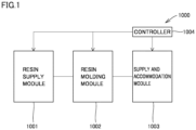
- FIG. 1 shows a functional block diagram of an exemplary resin molding system in a first embodiment.
- a resin molding system 1000 shown in Fig. 1 includes a resin supply module 1001 capable of supplying a resin material, a resin molding module 1002 capable of manufacturing a resin-molded product by compression molding an object, a supply and accommodation module 1003 capable of supplying a yet-to-be-molded object, where a compression-molded resin-molded product can be accommodated, and a controller 1004.
- Controller 1004 is configured to control resin supply module 1001, resin molding module 1002, and supply and accommodation module 1003.
- Resin supply module 1001, resin molding module 1002, and supply and accommodation module 1003 are attachable to and removable from one another and also replaceable.
- Resin supply module 1001 includes a resin material supply apparatus capable of supplying a resin material to resin molding module 1002.
- Resin molding module 1002 includes a resin molding apparatus in the embodiment. Details of a resin molding apparatus 1 in the embodiment will be described later. A plurality of resin molding modules 1002 may be provided.
- Supply and accommodation module 1003 includes a supply apparatus capable of supplying an object yet to be resin-molded and an accommodation apparatus where a compression-molded resin-molded product can be accommodated.
- the resin-molded product compression-molded with a resin by the resin molding apparatus is accommodated in supply and accommodation module 1003.
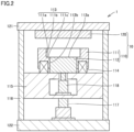
- Fig. 2 shows a schematic cross-sectional view of the resin molding apparatus in the first embodiment which represents an exemplary resin molding apparatus in the embodiment.
- resin molding apparatus 1 in the first embodiment includes a compression mold 10.
- Compression mold 10 includes a first mold 110 and a second mold 120 arranged above first mold 110 as facing first mold 110.
- First mold 110 includes a side surface member 111 and a bottom surface member 112.
- Side surface member 111 is arranged to surround bottom surface member 112.
- Side surface member 111 includes an inner peripheral surface located on a bottom surface member 112 side of side surface member 111, and the inner peripheral surface includes a step height 113.
- Step height 113 includes a first surface 11 1a of side surface member 111, a second surface 111b that extends from first surface 111a toward bottom surface member 112, and a third surface 111c that extends downward from second surface 111b.
- Each of first surface 111a and third surface 111c is perpendicular to second surface 111b.
- Bottom surface member 112 includes an upper surface 112a where a resin material can be arranged and a slide surface 112b that extends downward from a periphery of upper surface 112a. Slide surface 112b is in contact with third surface 111c of side surface member 111 and slidable with respect to third surface 111c of side surface member 111.
- Resin molding apparatus 1 further includes an upper fixed plate 121, a lower fixed plate 122, and a moving plate 115.
- a plurality of pillar portions 116 vertically extend between upper fixed plate 121 and lower fixed plate 122.
- the plurality of pillar portions 116 have one ends fixed to upper fixed plate 121 and have the other ends fixed to lower fixed plate 122.
- An elastic member 114 is provided between side surface member 111 and moving plate 115.
- Resin molding apparatus 1 further includes a first drive mechanism 117 among the plurality of pillar portions 116 on lower fixed plate 122.
- First drive mechanism 117 can move moving plate 115 upward and downward.
- Upper fixed plate 121 and lower fixed plate 122 are fixed and immobilized. Therefore, moving plate 115 is movable relatively to upper fixed plate 121 and lower fixed plate 122.
- First drive mechanism 117 can move upward and downward, that is, can lift and lower, side surface member 111 and bottom surface member 112 with moving plate 115 being interposed.
- Resin molding apparatus 1 further includes a second drive mechanism 118 in the inside of moving plate 115.
- Second drive mechanism 118 can move upward and downward, that is, can lift and lower, bottom surface member 112. Bottom surface member 112 is thus movable relatively to side surface member 111.
- a method of manufacturing a resin-molded product in the first embodiment which represents an exemplary method of manufacturing a resin-molded product in the embodiment will be described below with reference to schematic cross-sectional views in Figs. 2 to 8 .
- a step of preparing compression mold 10 is performed.
- the step of preparing compression mold 10 can be performed, for example, by setting first mold 110 on moving plate 115 and setting second mold 120 on upper fixed plate 121.
- a step of setting an object 201 on second mold 120 is performed.
- the step of setting object 201 on second mold 120 can be performed, for example, by holding object 201 on second mold 120 by suction.
- object 201 include a lead frame, a substrate, a substrate made of a semiconductor (a silicon wafer or the like), a substrate made of a metal, a substrate made of glass, a substrate made of ceramic, or a wiring board.
- a step of supplying a resin material 202 while third surface 111c of side surface member 111 is not exposed is performed.
- the step of supplying resin material 202 while third surface 111c of side surface member 111 is not exposed can be performed, for example, by supplying resin material 202 into a cavity defined by first surface 111a and second surface 11 1b of side surface member 111 and upper surface 112a of bottom surface member 112 such that third surface 111c of side surface member 111 and resin material 202 do not come in contact with each other.
- the order of the step of setting object 201 on second mold 120 and the step of supplying resin material 202 while third surface 111c of side surface member 111 is not exposed is not particularly limited.
- a step of moving first mold 110 toward second mold 120 is performed.
- the step of moving first mold 110 toward second mold 120 is performed, for example, by movement of moving plate 115 in a direction toward second mold 120 by first drive mechanism 117.
- a step of resin-molding object 201 with resin material 202 is performed.
- the step of resin-molding object 201 with resin material 202 can be performed, for example, as below.
- Resin-molded object 300 is taken out of compression mold 10.
- Resin-molded object 300 includes a surrounding portion 220 that extends downward to surround a periphery of a bottom surface.
- Surrounding portion 220 is in a shape in conformity with first surface 111a and second surface 11 1b of side surface member 111.
- a step of removal of unnecessary surrounding portion 220 from object 300 is performed.
- a resin-molded product 301 obtained by removing surrounding portion 220 from resin-molded object 300 as shown, for example, in the schematic cross-sectional view in Fig. 8 can also be manufactured.
- third surface 111c of side surface member 111 is not exposed while resin material 202 is supplied. Therefore, according to resin molding apparatus 1, introduction of the resin in between constituent members of the compression mold can be suppressed without the use of a release film.
- an inner peripheral surface 1111a of a side surface member 1111 of a first mold 1100 shown, for example, in the schematic cross-sectional view in Fig. 9 (a) does not include step height 113 as in resin molding apparatus 1 in the first embodiment but extends in a vertical direction (an upward/downward direction). Therefore, in conventional first mold 1100 constructed as such, a resin 202c in contact with inner peripheral surface 1111a of side surface member 1111 is present while resin material 202 is supplied.
- slide surface 112b of bottom surface member 112 slides over resin 202c that adheres to inner peripheral surface 1111a of side surface member 1111 and moves as drawing resin 202c in between inner peripheral surface 1111a of side surface member 1111 and slide surface 112b of bottom surface member 112.
- Fig. 10 shows a photograph of a portion between inner peripheral surface 1111a of side surface member 1111 and slide surface 112b of bottom surface member 112 after resin molding in the conventional resin molding apparatus including first mold 1100 shown in Fig. 9 (a) and (b) .
- black spots corresponding to the resin residues can visually be recognized between inner peripheral surface 1111a of conventional side surface member 1111 and slide surface 112b of bottom surface member 112.
- Fig. 11 shows a photograph of a resin-molded product resin-molded with the use of the conventional resin molding apparatus including first mold 1100 shown in Fig. 9 (a) and (b) .
- first mold 1100 shown in Fig. 9 (a) and (b) .
- Fig. 11 shows a photograph of a resin-molded product resin-molded with the use of the conventional resin molding apparatus including first mold 1100 shown in Fig. 9 (a) and (b) .
- resin flashes that protrude outward from the periphery can visually be recognized.
- third surface 111c of side surface member 111 is not in contact with resin material 202 while resin material 202 is supplied.
- resin molding apparatus 1 in the first embodiment can allow suppression of introduction of the resin in between constituent members of the compression mold without the use of a release film.
- Fig. 13 shows a photograph of a portion between third surface 111c of side surface member 111 and slide surface 112b of bottom surface member 112 after resin molding in resin molding apparatus 1 in the first embodiment. As shown in Fig. 13 , no black spot corresponding to the resin residues can visually be recognized between third surface 111c of side surface member 111 and slide surface 112b of bottom surface member 112 of resin molding apparatus 1 in the first embodiment.
- Fig. 14 shows a photograph of a resin-molded product resin-molded with the use of resin molding apparatus 1 in the first embodiment. As shown in Fig. 14 , at a periphery of resin-molded product 301 resin-molded with the use of resin molding apparatus 1 in the first embodiment, no resin flash that protrudes outward from the periphery can visually be recognized.
- a press mechanism capable of lifting and lowering side surface member 111 and bottom surface member 112 only with the use of first drive mechanism 117 without second drive mechanism 118 in the construction in Fig. 2 has been known.
- resin molding can be carried out only with a construction where the press mechanism includes only a single drive mechanism as such.
- the construction provided with two drive mechanisms (first drive mechanism 117 and second drive mechanism 118) as in the present embodiment is particularly effective.
- the resin molding apparatus can also be constructed such that side surface member 111 and bottom surface member 112 can be lifted and lowered only with first drive mechanism 117 without second drive mechanism 118 in the construction in Fig. 2 .
- second drive mechanism 118 capable of lifting and lowering bottom surface member 112 independently of side surface member 111 is provided separately from first drive mechanism 117.
- the third surface of the side surface member not being exposed while the resin material is supplied herein means that an upper end of the third surface of the side surface member of the resin molding apparatus is flush with an upper end of the slide surface of the bottom surface member or located below the slide surface of the bottom surface member at a time point at least before a time point when supply of the resin material is expected.
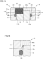
- Fig. 15 (a) shows a schematic cross-sectional view of first mold 10 while a resin material is supplied in the resin molding apparatus in a second embodiment which represents another exemplary resin molding apparatus in the embodiment.
- Fig. 15 (b) shows a schematic cross-sectional view of first mold 10 during resin molding in the resin molding apparatus in the second embodiment.
- the resin molding apparatus in the second embodiment is characterized in further including a sealing material 130 in third surface 111c of side surface member 111.
- a sealing material 130 for example, packing, a gasket, or a resin ring can be employed as sealing material 130. Sealing material 130 may be attached to bottom surface member 112.
- Fig. 16 shows a schematic enlarged cross-sectional view of first mold 10 shown in Fig. 15 (b) .
- a gap between third surface 111c of side surface member 111 and slide surface 112b of bottom surface member 112 can be filled with sealing material 130 and leakage of molten resin 202a to the gap between third surface 111c of side surface member 111 and slide surface 112b of bottom surface member 112 due to a molding pressure in a direction shown with an arrow 401 can be suppressed.
- the exemplary method of manufacturing a resin-molded product in the embodiment described above should only include a step of setting sealing material 130 in third surface 111c of side surface member 111 at least before the step of supplying resin material 202 described above.
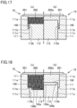
- Fig. 17 (a) shows a schematic cross-sectional view of first mold 10 while a resin material is supplied in the resin molding apparatus in a third embodiment which represents yet another exemplary resin molding apparatus in the embodiment.
- Fig. 17 (b) shows a schematic cross-sectional view of first mold 10 during resin molding in the resin molding apparatus in the third embodiment.
- the resin molding apparatus in the third embodiment is characterized in further including a consumable 140 arranged between first surface 111a and second surface 11 1b of side surface member 111 and slide surface 112b of bottom surface member 112.
- a consumable 140 arranged between first surface 111a and second surface 11 1b of side surface member 111 and slide surface 112b of bottom surface member 112.
- paper or rubber can be employed as consumable 140.
- an upper surface between third surface 111c of side surface member 111 and slide surface 112b of bottom surface member 112 is covered with consumable140, so that leakage of molten resin 202a to the gap between third surface 111c of side surface member 111 and slide surface 112b of bottom surface member 112 due to a molding pressure can be suppressed.
- the exemplary method of manufacturing a resin-molded product in the embodiment described above should only include a step of setting consumable 140 between first surface 111a and second surface 11 1b of side surface member 111 and slide surface 111c of bottom surface member 112 at least before the step of supplying resin material 202 described above.
- Fig. 18 (a) shows a schematic cross-sectional view of first mold 10 while a resin material is supplied in the resin molding apparatus in a fourth embodiment which represents still another exemplary resin molding apparatus in the embodiment.
- Fig. 18 (b) shows a schematic cross-sectional view of first mold 10 during resin molding in the resin molding apparatus in the fourth embodiment.
- the resin molding apparatus in the fourth embodiment is characterized in that a recess 150 is provided in upper surface 112a of bottom surface member 112.
- Recess 150 includes a flat bottom surface 150a and an inner peripheral surface 150b that extends obliquely upward from a periphery of bottom surface 150a.
- Fig. 19 shows a schematic plan view of object 300 resin-molded with the resin molding apparatus in the fourth embodiment.
- resin-molded object 300 includes a projecting portion 500 in conformity with the shape of recess 150 in upper surface 112a of bottom surface member 112.
- projecting portion 500 is provided with flat bottom surface 500a. Therefore, in manufacturing of a resin-molded product with the use of the resin molding apparatus in the fourth embodiment, as shown in the schematic plan view in Fig. 20 , in removal by cutting of surrounding portion 220 which is an unnecessary portion, the surrounding portion can be removed while flat bottom surface 500a of projecting portion 500 is suctioned to adhere in a stable manner. Therefore, efficiency in manufacturing of resin-molded product 301 can be improved.
- projecting portion 500 includes an outer peripheral surface 500b inclined with respect to bottom surface 500a. Therefore, resin-molded product 301 can more readily be taken out of compression mold 10.
- inner peripheral surface 150b of recess 150 is described as being inclined with respect to bottom surface 150a in the fourth embodiment, inner peripheral surface 150b of recess 150 may be perpendicular to bottom surface 150a.
- Fig. 21 (a) shows a schematic cross-sectional view of first mold 10 while a resin material is supplied in the resin molding apparatus in a fifth embodiment which represents still another exemplary resin molding apparatus in the embodiment.
- Fig. 21 (b) shows a schematic cross-sectional view of first mold 10 during resin molding in the resin molding apparatus in the fifth embodiment.
- the resin molding apparatus in the fifth embodiment is characterized in that first surface 111a of side surface member 111 is inclined with respect to second surface 11 1b.
- first surface 111a of side surface member 111 is inclined with respect to second surface 111b. Therefore, the resin molding apparatus in the fifth embodiment can allow resin-molded product 301 to be taken out more easily from compression mold 10 than the resin molding apparatuses in the first to fourth embodiments where first surface 111a of side surface member 111 is perpendicular to second surface 111b.
- a compression mold a resin molding apparatus, a resin molding system, and a method of manufacturing a resin-molded product can be provided.
- 1 resin molding apparatus 10 compression mold; 110, 1100 first mold; 120 second mold; 111, 1111 side surface member; 111a first surface; 111b second surface; 111c third surface; 112 bottom surface member; 112a upper surface; 112b slide surface; 113 step height; 114 elastic member; 115 moving plate; 116 pillar portion; 117 first drive mechanism; 118 second drive mechanism; 121 upper fixed plate; 122 lower fixed plate; 130 sealing material; 140 consumable; 150 recess; 150a, 500a bottom surface; 150b, 1111a inner peripheral surface; 201 object; 202 resin material; 202a molten resin; 202b cured resin; 202c resin; 220 surrounding portion; 300 resin-molded object; 301, 3010 resin-molded product; 401 arrow; 500 projecting portion; 500b outer peripheral surface; 1000 resin molding system; 1001 resin supply module; 1002 resin molding module; 1003 supply and accommodation module; 1004 controller
Landscapes
- Engineering & Computer Science (AREA)
- Mechanical Engineering (AREA)
- Casting Or Compression Moulding Of Plastics Or The Like (AREA)
- Moulds For Moulding Plastics Or The Like (AREA)
Abstract
Description
- The present disclosure relates to a compression mold, a resin molding apparatus, a resin molding system, and a method of manufacturing a resin-molded product.
- An electronic component such as a semiconductor chip mounted on a substrate has conventionally been sealed with a resin by compression molding with the use of a resin molding apparatus including a compression mold composed of upper and lower molds.
- For example,
PTL 1 discloses an object resin sealing method of sealing with a resin, an object in molds that face each other, the object resin sealing method including a first procedure to release the molds from a portion of the object not sealed with the resin to set a state that only the resin is in contact with a specific mold of the molds and a second procedure to wait for molding and shrinkage of the resin in this state. - PTL 1:
Japanese Patent Laying-Open No. 2005-305951 - According to the resin sealing method described in
PTL 1, a release film for releasing the molds from the object does not have to be used. - In the resin sealing method described in
PTL 1, however, when a compression mold is slid with respect to a lower frame-shaped mold in compression molding of the object with the upper mold and the lower mold, a heated and molten liquid resin may be introduced in between the lower frame-shaped mold and the compression mold. When the liquid resin is introduced in between the molds, some of the liquid resin returns to the molds and is cured, and thereafter causes resin residues and resin flashes. The resin residues cause contamination of the mold. The resin flashes introduced in a resin-molded product cause defective products. Therefore, the lower mold has to frequently be disassembled and cleaned to take out the resin residues. - In order to prevent the liquid resin from being introduced in between the frame-shaped mold and the compression mold, a release film may also be provided in the frame-shaped mold.
- When a frame height of the frame-shaped mold is higher than the compression mold, however, the release film may not sufficiently be extended or may be broken. Even if the release film can be extended, a part of the extended release film may be crinkled at the time of clamping of the upper mold and the lower mold, and may be introduced in the resin in the resin-molded product.
- According to an embodiment disclosed herein, a compression mold including a first mold and a second mold arranged above the first mold as facing the first mold can be provided, in which the first mold includes a side surface member and a bottom surface member, the side surface member includes a step height on a bottom surface member side of the side surface member, the step height includes a first surface of the side surface member, a second surface that extends from the first surface toward the bottom surface member, and a third surface that extends downward from the second surface, the bottom surface member includes an upper surface where a resin material can be arranged and a slide surface that extends downward from the upper surface and is slidable with respect to the third surface of the side surface member, and the third surface of the side surface member is not exposed while the resin material is supplied.
- According to the embodiment disclosed herein, a resin molding apparatus including the compression mold can be provided.
- According to the embodiment disclosed herein, a resin molding system including the resin molding apparatus can be provided.
- According to the embodiment disclosed herein, a method of manufacturing a resin-molded product that includes preparing a compression mold can be provided, in which the compression mold includes a first mold and a second mold arranged above the first mold as facing the first mold, the first mold includes a side surface member and a bottom surface member, the side surface member includes a step height on a bottom surface member side of the side surface member, the step height includes a first surface of the side surface member, a second surface that extends from the first surface toward the bottom surface member, and a third surface that extends downward from the second surface, and the bottom surface member includes an upper surface where a resin material can be arranged and a slide surface that extends downward from the bottom surface and is slidable with respect to the third surface of the side surface member. The method of manufacturing a resin-molded product further includes setting an object on the second mold, supplying a resin material while the third surface of the side surface member is not exposed, and resin-molding the object with the resin material.
- According to the embodiment disclosed herein, a compression mold, a resin molding apparatus, a resin molding system, and a method of manufacturing a resin-molded product that allow suppression of introduction of a resin in between constituent members of the compression mold without the use of a release film can be provided.
-
-
Fig. 1 is a functional block diagram of an exemplary resin molding system in a first embodiment. -
Fig. 2 is a schematic cross-sectional view of an exemplary resin molding apparatus in the first embodiment. -
Fig. 3 is a schematic cross-sectional view for illustrating a part of a step in an exemplary method of manufacturing a resin-molded product in the first embodiment. -
Fig. 4 is a schematic cross-sectional view for illustrating another part of the step in the exemplary method of manufacturing a resin-molded product in the first embodiment. -
Fig. 5 is a schematic cross-sectional view for illustrating yet another part of the step in the exemplary method of manufacturing a resin-molded product in the first embodiment. -
Fig. 6 is a schematic cross-sectional view for illustrating still another part of the step in the exemplary method of manufacturing a resin-molded product in the first embodiment. -
Fig. 7 is a schematic cross-sectional view of an exemplary resin-molded object in the first embodiment. -
Fig. 8 is a schematic cross-sectional view of an exemplary resin-molded product in the first embodiment. -
Fig. 9 (a) is a schematic cross-sectional view of a first mold while a resin material is supplied in a conventional resin molding apparatus and (b) is a schematic cross-sectional view of the first mold during resin molding in the conventional resin molding apparatus. -
Fig. 10 shows a photograph of a portion between an inner peripheral surface of a side surface member and a slide surface of a bottom surface member after resin molding in the conventional resin molding apparatus including the first mold shown inFig. 9 (a) and (b) . -
Fig. 11 shows a photograph of a resin-molded product resin-molded with the use of the conventional resin molding apparatus including the first mold shown inFig. 9 (a) and (b) . -
Fig. 12 (a) is a schematic cross-sectional view of the first mold while a resin material is supplied in the resin molding apparatus in the first embodiment and (b) is a schematic cross-sectional view of the first mold during resin molding in the resin molding apparatus in the first embodiment. -
Fig. 13 shows a photograph of a portion between the inner peripheral surface of the side surface member and the slide surface of the bottom surface member after resin molding in the resin molding apparatus in the first embodiment. -
Fig. 14 shows a photograph of a resin-molded product resin-molded with the use of the resin molding apparatus in the first embodiment. -
Fig. 15 (a) is a schematic cross-sectional view of the first mold while a resin material is supplied in the resin molding apparatus in a second embodiment and (b) is a schematic cross-sectional view of the first mold during resin molding in the resin molding apparatus in the second embodiment. -
Fig. 16 is a schematic enlarged cross-sectional view of the first mold shown inFig. 15 (b) . -
Fig. 17 (a) is a schematic cross-sectional view of the first mold while a resin material is supplied in the resin molding apparatus in a third embodiment and (b) is a schematic cross-sectional view of the first mold during resin molding in the resin molding apparatus in the third embodiment. -
Fig. 18 (a) is a schematic cross-sectional view of the first mold while a resin material is supplied in the resin molding apparatus in a fourth embodiment and (b) is a schematic cross-sectional view of the first mold during resin molding in the resin molding apparatus in the fourth embodiment. -
Fig. 19 is a schematic plan view of an object resin-molded with the resin molding apparatus in the fourth embodiment. -
Fig. 20 is a schematic plan view of a resin-molded product manufactured with the resin molding apparatus in the fourth embodiment. -
Fig. 21 (a) is a schematic cross-sectional view of the first mold while a resin material is supplied in the resin molding apparatus in a fifth embodiment and (b) is a schematic cross-sectional view of the first mold during resin molding in the resin molding apparatus in the fifth embodiment. - An embodiment will be described below. In the drawings used for description of the embodiment, identical or corresponding elements have identical reference characters allotted.
-
Fig. 1 shows a functional block diagram of an exemplary resin molding system in a first embodiment. Aresin molding system 1000 shown inFig. 1 includes aresin supply module 1001 capable of supplying a resin material, aresin molding module 1002 capable of manufacturing a resin-molded product by compression molding an object, a supply andaccommodation module 1003 capable of supplying a yet-to-be-molded object, where a compression-molded resin-molded product can be accommodated, and acontroller 1004.Controller 1004 is configured to controlresin supply module 1001,resin molding module 1002, and supply andaccommodation module 1003. -
Resin supply module 1001,resin molding module 1002, and supply andaccommodation module 1003 are attachable to and removable from one another and also replaceable. -
Resin supply module 1001 includes a resin material supply apparatus capable of supplying a resin material to resinmolding module 1002. -
Resin molding module 1002 includes a resin molding apparatus in the embodiment. Details of aresin molding apparatus 1 in the embodiment will be described later. A plurality ofresin molding modules 1002 may be provided. - Supply and
accommodation module 1003 includes a supply apparatus capable of supplying an object yet to be resin-molded and an accommodation apparatus where a compression-molded resin-molded product can be accommodated. - The resin-molded product compression-molded with a resin by the resin molding apparatus is accommodated in supply and
accommodation module 1003. -
Fig. 2 shows a schematic cross-sectional view of the resin molding apparatus in the first embodiment which represents an exemplary resin molding apparatus in the embodiment. As shown inFig. 2 ,resin molding apparatus 1 in the first embodiment includes acompression mold 10.Compression mold 10 includes afirst mold 110 and asecond mold 120 arranged abovefirst mold 110 as facingfirst mold 110. -
First mold 110 includes aside surface member 111 and abottom surface member 112.Side surface member 111 is arranged to surroundbottom surface member 112.Side surface member 111 includes an inner peripheral surface located on abottom surface member 112 side ofside surface member 111, and the inner peripheral surface includes astep height 113.Step height 113 includes a first surface 11 1a ofside surface member 111, asecond surface 111b that extends fromfirst surface 111a towardbottom surface member 112, and athird surface 111c that extends downward fromsecond surface 111b. Each offirst surface 111a andthird surface 111c is perpendicular tosecond surface 111b. -
Bottom surface member 112 includes anupper surface 112a where a resin material can be arranged and aslide surface 112b that extends downward from a periphery ofupper surface 112a.Slide surface 112b is in contact withthird surface 111c ofside surface member 111 and slidable with respect tothird surface 111c ofside surface member 111. -
Resin molding apparatus 1 further includes an upper fixedplate 121, a lower fixedplate 122, and a movingplate 115. A plurality ofpillar portions 116 vertically extend between upperfixed plate 121 and lower fixedplate 122. The plurality ofpillar portions 116 have one ends fixed to upper fixedplate 121 and have the other ends fixed to lower fixedplate 122. Anelastic member 114 is provided betweenside surface member 111 and movingplate 115. -
Resin molding apparatus 1 further includes afirst drive mechanism 117 among the plurality ofpillar portions 116 on lower fixedplate 122.First drive mechanism 117 can move movingplate 115 upward and downward. Upperfixed plate 121 and lower fixedplate 122 are fixed and immobilized. Therefore, movingplate 115 is movable relatively to upper fixedplate 121 and lower fixedplate 122.First drive mechanism 117 can move upward and downward, that is, can lift and lower,side surface member 111 andbottom surface member 112 with movingplate 115 being interposed. -
Resin molding apparatus 1 further includes asecond drive mechanism 118 in the inside of movingplate 115.Second drive mechanism 118 can move upward and downward, that is, can lift and lower,bottom surface member 112.Bottom surface member 112 is thus movable relatively toside surface member 111. - A method of manufacturing a resin-molded product in the first embodiment which represents an exemplary method of manufacturing a resin-molded product in the embodiment will be described below with reference to schematic cross-sectional views in
Figs. 2 to 8 . Initially, as shown inFig. 2 , a step of preparingcompression mold 10 is performed. The step of preparingcompression mold 10 can be performed, for example, by settingfirst mold 110 on movingplate 115 and settingsecond mold 120 on upper fixedplate 121. - Then, as shown in
Fig. 3 , a step of setting anobject 201 onsecond mold 120 is performed. The step of settingobject 201 onsecond mold 120 can be performed, for example, by holdingobject 201 onsecond mold 120 by suction. Examples ofobject 201 include a lead frame, a substrate, a substrate made of a semiconductor (a silicon wafer or the like), a substrate made of a metal, a substrate made of glass, a substrate made of ceramic, or a wiring board. - Then, as shown in
Fig. 3 , a step of supplying aresin material 202 whilethird surface 111c ofside surface member 111 is not exposed is performed. The step of supplyingresin material 202 whilethird surface 111c ofside surface member 111 is not exposed can be performed, for example, by supplyingresin material 202 into a cavity defined byfirst surface 111a and second surface 11 1b ofside surface member 111 andupper surface 112a ofbottom surface member 112 such thatthird surface 111c ofside surface member 111 andresin material 202 do not come in contact with each other. - In the present embodiment, the order of the step of setting
object 201 onsecond mold 120 and the step of supplyingresin material 202 whilethird surface 111c ofside surface member 111 is not exposed is not particularly limited. - Then, as shown in
Fig. 4 , a step of movingfirst mold 110 towardsecond mold 120 is performed. The step of movingfirst mold 110 towardsecond mold 120 is performed, for example, by movement of movingplate 115 in a direction towardsecond mold 120 byfirst drive mechanism 117. - Then, a step of resin-
molding object 201 withresin material 202 is performed. The step of resin-molding object 201 withresin material 202 can be performed, for example, as below. - Initially, as shown in
Fig. 5 ,resin material 202a is heated and molten to becomemolten resin 202a, andsecond drive mechanism 118 pushes upupper surface 112a ofbottom surface member 112 above second surface 11 1b ofside surface member 111. At this time,side surface member 111 is pushed down andbottom surface member 112 is pushed up such thatelastic member 114 biased towardside surface member 111 by a pressure fromfirst mold 110 towardsecond mold 120 contracts. Thus, whileslide surface 112b ofbottom surface member 112 slides with respect tothird surface 111c ofside surface member 111,bottom surface member 112 moves upward relatively toside surface member 111. - Then, as shown in
Fig. 6 , whileupper surface 112a ofbottom surface member 112 is pushed up abovesecond surface 111b of side surface member 111 (on the side of second mold 120),molten resin 202a is further heated and cured to become a curedresin 202b. - Then, as shown, for example, in the schematic cross-sectional view in
Fig. 7 , a resin-moldedobject 300 is taken out ofcompression mold 10. Resin-moldedobject 300 includes a surroundingportion 220 that extends downward to surround a periphery of a bottom surface. Surroundingportion 220 is in a shape in conformity withfirst surface 111a and second surface 11 1b ofside surface member 111. - Thereafter, when surrounding
portion 220 shown inFig. 7 is an unnecessary portion, a step of removal of unnecessary surroundingportion 220 fromobject 300 is performed. Thus, a resin-moldedproduct 301 obtained by removing surroundingportion 220 from resin-moldedobject 300 as shown, for example, in the schematic cross-sectional view inFig. 8 can also be manufactured. - In
resin molding apparatus 1 in the first embodiment,third surface 111c ofside surface member 111 is not exposed whileresin material 202 is supplied. Therefore, according toresin molding apparatus 1, introduction of the resin in between constituent members of the compression mold can be suppressed without the use of a release film. - In a conventional resin molding apparatus, an inner
peripheral surface 1111a of aside surface member 1111 of afirst mold 1100 shown, for example, in the schematic cross-sectional view inFig. 9 (a) does not includestep height 113 as inresin molding apparatus 1 in the first embodiment but extends in a vertical direction (an upward/downward direction). Therefore, in conventionalfirst mold 1100 constructed as such, aresin 202c in contact with innerperipheral surface 1111a ofside surface member 1111 is present whileresin material 202 is supplied. - Thereafter, during resin molding as shown, for example, in the schematic cross-sectional view in
Fig. 9 (b) ,slide surface 112b ofbottom surface member 112 slides overresin 202c that adheres to innerperipheral surface 1111a ofside surface member 1111 and moves as drawingresin 202c in between innerperipheral surface 1111a ofside surface member 1111 andslide surface 112b ofbottom surface member 112. - Therefore, in the conventional resin molding apparatus, after
resin 202c drawn in between innerperipheral surface 111 1a ofside surface member 1111 andslide surface 112b ofbottom surface member 112 is cured, resin residues which cause contamination of the mold or resin flashes which cause defective products by being introduced in a resin-molded product are caused. -
Fig. 10 shows a photograph of a portion between innerperipheral surface 1111a ofside surface member 1111 andslide surface 112b ofbottom surface member 112 after resin molding in the conventional resin molding apparatus includingfirst mold 1100 shown inFig. 9 (a) and (b) . As shown inFig. 10 , black spots corresponding to the resin residues can visually be recognized between innerperipheral surface 1111a of conventionalside surface member 1111 andslide surface 112b ofbottom surface member 112. -
Fig. 11 shows a photograph of a resin-molded product resin-molded with the use of the conventional resin molding apparatus includingfirst mold 1100 shown inFig. 9 (a) and (b) . As shown inFig. 11 , at a periphery of a resin-moldedproduct 3010 resin-molded with the use of the conventional resin molding apparatus, resin flashes that protrude outward from the periphery can visually be recognized. - In
resin molding apparatus 1 in the first embodiment, on the other hand, as shown, for example, in the schematic cross-sectional view inFig. 12 (a) ,third surface 111c ofside surface member 111 is not in contact withresin material 202 whileresin material 202 is supplied. - Therefore, even when
slide surface 112b ofbottom surface member 112 moves upward while it slides overthird surface 111c ofside surface member 111 during resin molding as shown, for example, in the schematic cross-sectional view inFig. 12 (b) , no resin adheres tothird surface 111c ofside surface member 111 and hence an amount of resin drawn in betweenthird surface 111c ofside surface member 111 andslide surface 112b ofbottom surface member 112 can clearly be made smaller than in the case of the conventional resin molding apparatus includingfirst mold 1100 shown inFig. 9 (a) and (b) . - Therefore,
resin molding apparatus 1 in the first embodiment can allow suppression of introduction of the resin in between constituent members of the compression mold without the use of a release film. -
Fig. 13 shows a photograph of a portion betweenthird surface 111c ofside surface member 111 andslide surface 112b ofbottom surface member 112 after resin molding inresin molding apparatus 1 in the first embodiment. As shown inFig. 13 , no black spot corresponding to the resin residues can visually be recognized betweenthird surface 111c ofside surface member 111 andslide surface 112b ofbottom surface member 112 ofresin molding apparatus 1 in the first embodiment. - Therefore, as is clear from comparison between
Figs. 10 and13 , it can be seen that the amount of resin residues can be made smaller inresin molding apparatus 1 in the first embodiment than in the conventional resin molding apparatus described above. -
Fig. 14 shows a photograph of a resin-molded product resin-molded with the use ofresin molding apparatus 1 in the first embodiment. As shown inFig. 14 , at a periphery of resin-moldedproduct 301 resin-molded with the use ofresin molding apparatus 1 in the first embodiment, no resin flash that protrudes outward from the periphery can visually be recognized. - Therefore, as is clear from comparison between
Figs. 11 and14 , it can be seen that resin flashes at the periphery of resin-moldedproduct 301 can be less inresin molding apparatus 1 in the first embodiment than in the conventional resin molding apparatus described above. - Description of the present embodiment where two drive mechanisms of
first drive mechanism 117 capable of lifting and loweringside surface member 111 andbottom surface member 112 with movingplate 115 being interposed andsecond drive mechanism 118 capable of lifting and loweringbottom surface member 112 are provided will supplementarily be provided. - For example, a press mechanism capable of lifting and lowering
side surface member 111 andbottom surface member 112 only with the use offirst drive mechanism 117 withoutsecond drive mechanism 118 in the construction inFig. 2 has been known. In manufacturing of a product (resin-molded product) relatively small in thickness such as a thickness not larger than 2 mm, resin molding can be carried out only with a construction where the press mechanism includes only a single drive mechanism as such. In manufacturing of a product (resin-molded product) relatively large in thickness such as a thickness exceeding 2 mm, however, a distance over whichside surface member 111 andbottom surface member 112 slide relatively to each other during resin molding becomes long and appropriate resin molding may not be carried out only by expansion and contraction ofelastic member 114 interposed betweenside surface member 111 and movingplate 115. In such a case, by providing two drive mechanisms (first drive mechanism 117 and second drive mechanism 118) as in the present embodiment, appropriate resin molding can be carried out even when the distance over whichside surface member 111 andbottom surface member 112 slide relatively to each other during resin molding becomes relatively long. - In manufacturing of a product (resin-molded product) relatively large in thickness such as a thickness exceeding 2 mm, an area of contact between a mold (for example, first mold 110) and a resin-molded product becomes large. Therefore, adhesive force between the mold and the resin-molded product becomes greater and mold release (taking the resin-molded product out of the mold after resin molding) may become difficult. By providing a drive mechanism capable of driving
side surface member 111 andbottom surface member 112 to independently lift or lower at least one of them in such a case, mold release can be facilitated. - An exemplary case will be described. In a mold release operation, only
side surface member 111 is lowered to release the resin-molded product and thereafter sidesurface member 111 is lifted to clampobject 201 as shown inFig. 4 , and then onlybottom surface member 112 is lowered to release the resin-molded product. Conversely, onlybottom surface member 112 can also be lowered first and thereafter onlyside surface member 111 can also be lowered to release the resin-molded product. - In manufacturing of a product with a relatively large thickness, use of the release film tends to result in crinkles, which may cause defective molding such as a poor appearance of the resin-molded product. Therefore, the construction provided with two drive mechanisms (
first drive mechanism 117 and second drive mechanism 118) as in the present embodiment is particularly effective. In manufacturing of a product (resin-molded product) relatively small in thickness, however, the resin molding apparatus can also be constructed such thatside surface member 111 andbottom surface member 112 can be lifted and lowered only withfirst drive mechanism 117 withoutsecond drive mechanism 118 in the construction inFig. 2 . - For the construction including the drive mechanism capable of lifting and lowering
first mold 110 described in the present embodiment,second drive mechanism 118 capable of lifting and loweringbottom surface member 112 independently ofside surface member 111 is provided separately fromfirst drive mechanism 117. A drive mechanism capable of lifting and loweringside surface member 111 independently ofbottom surface member 112, however, can also be provided separately fromfirst drive mechanism 117. - "The third surface of the side surface member not being exposed while the resin material is supplied" herein means that an upper end of the third surface of the side surface member of the resin molding apparatus is flush with an upper end of the slide surface of the bottom surface member or located below the slide surface of the bottom surface member at a time point at least before a time point when supply of the resin material is expected.
-
Fig. 15 (a) shows a schematic cross-sectional view offirst mold 10 while a resin material is supplied in the resin molding apparatus in a second embodiment which represents another exemplary resin molding apparatus in the embodiment.Fig. 15 (b) shows a schematic cross-sectional view offirst mold 10 during resin molding in the resin molding apparatus in the second embodiment. The resin molding apparatus in the second embodiment is characterized in further including a sealingmaterial 130 inthird surface 111c ofside surface member 111. For example, packing, a gasket, or a resin ring can be employed as sealingmaterial 130.Sealing material 130 may be attached tobottom surface member 112. -
Fig. 16 shows a schematic enlarged cross-sectional view offirst mold 10 shown inFig. 15 (b) . As shown inFig. 16 , in the resin molding apparatus in the second embodiment, a gap betweenthird surface 111c ofside surface member 111 andslide surface 112b ofbottom surface member 112 can be filled with sealingmaterial 130 and leakage ofmolten resin 202a to the gap betweenthird surface 111c ofside surface member 111 andslide surface 112b ofbottom surface member 112 due to a molding pressure in a direction shown with anarrow 401 can be suppressed. - In manufacturing of a resin-molded product with the use of the resin molding apparatus in the second embodiment, the exemplary method of manufacturing a resin-molded product in the embodiment described above should only include a step of setting sealing
material 130 inthird surface 111c ofside surface member 111 at least before the step of supplyingresin material 202 described above. - Since description of the second embodiment is otherwise similar to that of the first embodiment, the description will not be provided.
-
Fig. 17 (a) shows a schematic cross-sectional view offirst mold 10 while a resin material is supplied in the resin molding apparatus in a third embodiment which represents yet another exemplary resin molding apparatus in the embodiment.Fig. 17 (b) shows a schematic cross-sectional view offirst mold 10 during resin molding in the resin molding apparatus in the third embodiment. The resin molding apparatus in the third embodiment is characterized in further including a consumable 140 arranged betweenfirst surface 111a and second surface 11 1b ofside surface member 111 andslide surface 112b ofbottom surface member 112. For example, paper or rubber can be employed asconsumable 140. - In the resin molding apparatus in the third embodiment, an upper surface between
third surface 111c ofside surface member 111 andslide surface 112b ofbottom surface member 112 is covered with consumable140, so that leakage ofmolten resin 202a to the gap betweenthird surface 111c ofside surface member 111 andslide surface 112b ofbottom surface member 112 due to a molding pressure can be suppressed. - In manufacturing of a resin-molded product with the use of the resin molding apparatus in the third embodiment, the exemplary method of manufacturing a resin-molded product in the embodiment described above should only include a step of setting consumable 140 between
first surface 111a and second surface 11 1b ofside surface member 111 andslide surface 111c ofbottom surface member 112 at least before the step of supplyingresin material 202 described above. - Since description of the third embodiment is otherwise similar to that of the first and second embodiments, the description will not be provided.
-
Fig. 18 (a) shows a schematic cross-sectional view offirst mold 10 while a resin material is supplied in the resin molding apparatus in a fourth embodiment which represents still another exemplary resin molding apparatus in the embodiment.Fig. 18 (b) shows a schematic cross-sectional view offirst mold 10 during resin molding in the resin molding apparatus in the fourth embodiment. The resin molding apparatus in the fourth embodiment is characterized in that arecess 150 is provided inupper surface 112a ofbottom surface member 112.Recess 150 includes aflat bottom surface 150a and an innerperipheral surface 150b that extends obliquely upward from a periphery ofbottom surface 150a. -
Fig. 19 shows a schematic plan view ofobject 300 resin-molded with the resin molding apparatus in the fourth embodiment. As shown inFig. 19 , resin-moldedobject 300 includes a projectingportion 500 in conformity with the shape ofrecess 150 inupper surface 112a ofbottom surface member 112. - As shown in
Fig. 19 , projectingportion 500 is provided withflat bottom surface 500a. Therefore, in manufacturing of a resin-molded product with the use of the resin molding apparatus in the fourth embodiment, as shown in the schematic plan view inFig. 20 , in removal by cutting of surroundingportion 220 which is an unnecessary portion, the surrounding portion can be removed whileflat bottom surface 500a of projectingportion 500 is suctioned to adhere in a stable manner. Therefore, efficiency in manufacturing of resin-moldedproduct 301 can be improved. - In the resin molding apparatus in the fourth embodiment, projecting
portion 500 includes an outerperipheral surface 500b inclined with respect tobottom surface 500a. Therefore, resin-moldedproduct 301 can more readily be taken out ofcompression mold 10. - Though inner
peripheral surface 150b ofrecess 150 is described as being inclined with respect tobottom surface 150a in the fourth embodiment, innerperipheral surface 150b ofrecess 150 may be perpendicular tobottom surface 150a. - Since description of the fourth embodiment is otherwise similar to that of the first to third embodiments, the description will not be provided.
-
Fig. 21 (a) shows a schematic cross-sectional view offirst mold 10 while a resin material is supplied in the resin molding apparatus in a fifth embodiment which represents still another exemplary resin molding apparatus in the embodiment.Fig. 21 (b) shows a schematic cross-sectional view offirst mold 10 during resin molding in the resin molding apparatus in the fifth embodiment. The resin molding apparatus in the fifth embodiment is characterized in thatfirst surface 111a ofside surface member 111 is inclined with respect to second surface 11 1b. - In the resin molding apparatus in the fifth embodiment,
first surface 111a ofside surface member 111 is inclined with respect tosecond surface 111b. Therefore, the resin molding apparatus in the fifth embodiment can allow resin-moldedproduct 301 to be taken out more easily fromcompression mold 10 than the resin molding apparatuses in the first to fourth embodiments wherefirst surface 111a ofside surface member 111 is perpendicular tosecond surface 111b. - Since description of the fifth embodiment is otherwise similar to that of the first to fourth embodiments, the description will not be provided.
- Though the embodiments have been described as above, combination of the embodiments described above as appropriate is also originally intended.
- It should be understood that the embodiments disclosed herein are illustrative and non-restrictive in every respect. The scope of the present invention is defined by the terms of the claims rather than the description above and is intended to include any modifications within the scope and meaning equivalent to the terms of the claims.
- According to the embodiments disclosed herein, a compression mold, a resin molding apparatus, a resin molding system, and a method of manufacturing a resin-molded product can be provided.
- 1 resin molding apparatus; 10 compression mold; 110, 1100 first mold; 120 second mold; 111, 1111 side surface member; 111a first surface; 111b second surface; 111c third surface; 112 bottom surface member; 112a upper surface; 112b slide surface; 113 step height; 114 elastic member; 115 moving plate; 116 pillar portion; 117 first drive mechanism; 118 second drive mechanism; 121 upper fixed plate; 122 lower fixed plate; 130 sealing material; 140 consumable; 150 recess; 150a, 500a bottom surface; 150b, 1111a inner peripheral surface; 201 object; 202 resin material; 202a molten resin; 202b cured resin; 202c resin; 220 surrounding portion; 300 resin-molded object; 301, 3010 resin-molded product; 401 arrow; 500 projecting portion; 500b outer peripheral surface; 1000 resin molding system; 1001 resin supply module; 1002 resin molding module; 1003 supply and accommodation module; 1004 controller
Claims (14)
- A compression mold comprising:a first mold; anda second mold arranged above the first mold as facing the first mold, whereinthe first mold includes a side surface member and a bottom surface member,the side surface member includes a step height on a bottom surface member side of the side surface member,the step height includes a first surface of the side surface member, a second surface that extends from the first surface toward the bottom surface member, and a third surface that extends downward from the second surface,the bottom surface member includes an upper surface where a resin material can be arranged and a slide surface that extends downward from the upper surface and is slidable with respect to the third surface of the side surface member, andthe third surface of the side surface member is not exposed while the resin material is supplied.
- The compression mold according to claim 1, further comprising a sealing material in the third surface of the side surface member.
- The compression mold according to claim 1 or 2, further comprising a consumable arranged between the first surface and the second surface of the side surface member and the slide surface of the bottom surface member.
- The compression mold according to any one of claims 1 to 3, wherein
the first surface of the side surface member is perpendicular to the second surface or inclined with respect to the second surface. - The compression mold according to any one of claims 1 to 4, wherein
the upper surface of the bottom surface member is provided with a recess. - The compression mold according to claim 5, whereinthe recess includes a bottom surface and an inner peripheral surface that extends upward from the bottom surface, andthe inner peripheral surface is perpendicular to the bottom surface or inclined with respect to the bottom surface.
- A resin molding apparatus comprising the compression mold according to any one of claims 1 to 6.
- The resin molding apparatus according to claim 7, further comprising a drive mechanism that lifts and lowers the first mold, wherein
the drive mechanism lifts and lowers one of the side surface member and the bottom surface member independently of the other. - A resin molding system comprising the resin molding apparatus according to claim 7 or 8.
- A method of manufacturing a resin-molded product, the method comprising:preparing a compression mold, the compression mold including a first mold and a second mold arranged above the first mold as facing the first mold, the first mold including a side surface member and a bottom surface member, the side surface member including a step height on a bottom surface member side of the side surface member, the step height including a first surface of the side surface member, a second surface that extends from the first surface toward the bottom surface member, and a third surface that extends downward from the second surface, the bottom surface member including an upper surface where a resin material can be arranged and a slide surface that extends downward from the bottom surface and is slidable with respect to the third surface of the side surface member;setting an object on the second mold;supplying a resin material while the third surface of the side surface member is not exposed; andresin-molding the object with the resin material.
- The method of manufacturing a resin-molded product according to claim 10, wherein
in the resin-molding the object, the object is resin-molded with the upper surface of the bottom surface member being lifted above the second surface of the side surface member. - The method of manufacturing a resin-molded product according to claim 10 or 11, further comprising setting a sealing material in the third surface of the side surface member at least before the supplying a resin material.
- The method of manufacturing a resin-molded product according to any one of claims 10 to 12, further comprising setting a consumable between the first surface and the second surface of the side surface member and the slide surface of the bottom surface member at least before setting a resin material.
- The method of manufacturing a resin-molded product according to any one of claims 10 to 13, further comprising removing an unnecessary portion from the resin-molded object.
Applications Claiming Priority (2)
| Application Number | Priority Date | Filing Date | Title |
|---|---|---|---|
| JP2020187831A JP7394739B2 (en) | 2020-11-11 | 2020-11-11 | Compression molds, resin molding equipment, resin molding systems, and methods for manufacturing resin molded products |
| PCT/JP2021/033285 WO2022102232A1 (en) | 2020-11-11 | 2021-09-10 | Compression mold, resin molding device, resin molding system, and method for manufacturing resin molded product |
Publications (2)
| Publication Number | Publication Date |
|---|---|
| EP4245497A1 true EP4245497A1 (en) | 2023-09-20 |
| EP4245497A4 EP4245497A4 (en) | 2024-09-18 |
Family
ID=81601870
Family Applications (1)
| Application Number | Title | Priority Date | Filing Date |
|---|---|---|---|
| EP21891480.2A Pending EP4245497A4 (en) | 2020-11-11 | 2021-09-10 | COMPRESSION MOLD, RESIN MOLDING DEVICE, RESIN MOLDING SYSTEM, AND METHOD FOR MANUFACTURING RESIN MOLDED PRODUCT |
Country Status (7)
| Country | Link |
|---|---|
| US (1) | US20240009899A1 (en) |
| EP (1) | EP4245497A4 (en) |
| JP (1) | JP7394739B2 (en) |
| KR (1) | KR20230093488A (en) |
| CN (1) | CN116529046B (en) |
| TW (1) | TWI797782B (en) |
| WO (1) | WO2022102232A1 (en) |
Families Citing this family (1)
| Publication number | Priority date | Publication date | Assignee | Title |
|---|---|---|---|---|
| US20250144857A1 (en) * | 2023-11-02 | 2025-05-08 | Intel Corporation | Molding system and molding method |
Family Cites Families (15)
| Publication number | Priority date | Publication date | Assignee | Title |
|---|---|---|---|---|
| US4184835A (en) * | 1978-09-28 | 1980-01-22 | General Electric Company | Mold apparatus |
| JP2005150350A (en) | 2003-11-14 | 2005-06-09 | Renesas Technology Corp | Manufacturing method of semiconductor device |
| JP4301991B2 (en) | 2004-04-26 | 2009-07-22 | 住友重機械工業株式会社 | Resin sealing method for molded products |
| NL1032947C2 (en) * | 2006-11-27 | 2008-05-28 | Ecim Technologies Bv | Device and method for forming products. |
| JP2009083438A (en) * | 2007-10-03 | 2009-04-23 | Towa Corp | Electronic component compression molding method |
| WO2011105640A1 (en) * | 2010-02-25 | 2011-09-01 | 한미반도체 주식회사 | Compression molding device and method |
| JP5174874B2 (en) * | 2010-09-16 | 2013-04-03 | Towa株式会社 | Compression molding die and compression molding method |
| JP5468574B2 (en) * | 2011-06-29 | 2014-04-09 | Towa株式会社 | Resin sealing molding method and apparatus for electronic parts |
| FR2999468B1 (en) * | 2012-12-14 | 2015-05-29 | Plastic Omnium Cie | COMPRESSION MOLDING BODY WITH IMPROVED SEALING |
| FR3029446B1 (en) * | 2014-12-05 | 2017-01-13 | Plastic Omnium Cie | MOLD FOR MANUFACTURING A PLASTIC PART COMPRISING A SYSTEM FOR REALIZING ORIFICES IN THE WORKPIECE |
| AU2016223748B2 (en) * | 2015-02-27 | 2020-07-09 | Huntsman Advanced Materials Licensing (Switzerland) Gmbh | A process for manufacturing a fiber reinforced composite article, the composite article obtained and the use thereof |
| CN108025474A (en) * | 2015-09-25 | 2018-05-11 | 沙特基础工业全球技术有限公司 | The method molded using mold insert and the device for it |
| JP6580519B2 (en) * | 2016-05-24 | 2019-09-25 | Towa株式会社 | Compression molding apparatus, resin-encapsulated product manufacturing apparatus, compression molding method, and resin-encapsulated product manufacturing method |
| IT201600076240A1 (en) * | 2016-07-20 | 2018-01-20 | Sacmi | PUNCH FOR COMPRESSION MOLDS |
| JP6585800B2 (en) * | 2018-10-16 | 2019-10-02 | アピックヤマダ株式会社 | Resin molding method and resin molding apparatus |
-
2020
- 2020-11-11 JP JP2020187831A patent/JP7394739B2/en active Active
-
2021
- 2021-09-10 KR KR1020237017756A patent/KR20230093488A/en active Pending
- 2021-09-10 WO PCT/JP2021/033285 patent/WO2022102232A1/en not_active Ceased
- 2021-09-10 US US18/035,115 patent/US20240009899A1/en active Pending
- 2021-09-10 EP EP21891480.2A patent/EP4245497A4/en active Pending
- 2021-09-10 CN CN202180073162.6A patent/CN116529046B/en active Active
- 2021-10-18 TW TW110138524A patent/TWI797782B/en active
Also Published As
| Publication number | Publication date |
|---|---|
| KR20230093488A (en) | 2023-06-27 |
| CN116529046B (en) | 2026-03-27 |
| TW202218847A (en) | 2022-05-16 |
| WO2022102232A1 (en) | 2022-05-19 |
| EP4245497A4 (en) | 2024-09-18 |
| US20240009899A1 (en) | 2024-01-11 |
| JP2022077141A (en) | 2022-05-23 |
| CN116529046A (en) | 2023-08-01 |
| JP7394739B2 (en) | 2023-12-08 |
| TWI797782B (en) | 2023-04-01 |
Similar Documents
| Publication | Publication Date | Title |
|---|---|---|
| CN110815707B (en) | Resin molding device and resin molding method | |
| CN105984081B (en) | Resin sealing apparatus and method of resin-sealing | |
| JP6580519B2 (en) | Compression molding apparatus, resin-encapsulated product manufacturing apparatus, compression molding method, and resin-encapsulated product manufacturing method | |
| KR101767323B1 (en) | Molded product manufacturing system and molded product manufacturing method | |
| JP3896274B2 (en) | Semiconductor resin sealing device | |
| CN111836707A (en) | Casting mold and resin molding apparatus including the same | |
| TW202039199A (en) | Resin molding device and method for manufacturing resin molded article | |
| EP4245497A1 (en) | Compression mold, resin molding device, resin molding system, and method for manufacturing resin molded product | |
| JP5364944B2 (en) | Mold | |
| WO2012165822A2 (en) | Apparatus and method for forming an encapsulation material for a light-emitting device | |
| WO2012128444A1 (en) | Encapsulating material moulding method | |
| CN116209554B (en) | Method for producing resin molded product | |
| CN114102952A (en) | Resin leakage prevention member, resin leakage prevention member supply mechanism, resin molding device, and resin molded article manufacturing method | |
| KR102553765B1 (en) | Resin molding apparatus and method of manufacturing resin molded product | |
| US9199396B2 (en) | Substrate carrier for molding electronic devices | |
| TWI910579B (en) | Compression forming apparatus and compression forming method | |
| TWI902006B (en) | Sealing resin for compression molding and forming method thereof | |
| TWI785738B (en) | Resin molding device and manufacturing method of resin molded article | |
| TWI913692B (en) | Compression forming apparatus and compression forming method | |
| JP7335647B2 (en) | Work transfer device and resin molding device | |
| JP2008084994A (en) | Manufacturing method and manufacturing apparatus for solid-state imaging device, and pasting apparatus | |
| CN120603693A (en) | Method for manufacturing resin molded product, molding die, and resin molding device | |
| TW201819137A (en) | Flat plate jig, resin molding apparatus, and resin molding method which protects an electronic component arranged on a wafer or a substrate with a simple structure without using a release film |
Legal Events
| Date | Code | Title | Description |
|---|---|---|---|
| STAA | Information on the status of an ep patent application or granted ep patent |
Free format text: STATUS: THE INTERNATIONAL PUBLICATION HAS BEEN MADE |
|
| PUAI | Public reference made under article 153(3) epc to a published international application that has entered the european phase |
Free format text: ORIGINAL CODE: 0009012 |
|
| STAA | Information on the status of an ep patent application or granted ep patent |
Free format text: STATUS: REQUEST FOR EXAMINATION WAS MADE |
|
| 17P | Request for examination filed |
Effective date: 20230611 |
|
| AK | Designated contracting states |
Kind code of ref document: A1 Designated state(s): AL AT BE BG CH CY CZ DE DK EE ES FI FR GB GR HR HU IE IS IT LI LT LU LV MC MK MT NL NO PL PT RO RS SE SI SK SM TR |
|
| DAV | Request for validation of the european patent (deleted) | ||
| DAX | Request for extension of the european patent (deleted) | ||
| A4 | Supplementary search report drawn up and despatched |
Effective date: 20240821 |
|
| RIC1 | Information provided on ipc code assigned before grant |
Ipc: B29C 43/36 20060101ALI20240814BHEP Ipc: B29C 43/34 20060101ALI20240814BHEP Ipc: B29C 43/18 20060101ALI20240814BHEP Ipc: B29C 33/12 20060101AFI20240814BHEP |
|
| STAA | Information on the status of an ep patent application or granted ep patent |
Free format text: STATUS: EXAMINATION IS IN PROGRESS |
|
| 17Q | First examination report despatched |
Effective date: 20250825 |