EP4245396B1 - Multifunktionales filterventil zur wasserbehandlung - Google Patents
Multifunktionales filterventil zur wasserbehandlung Download PDFInfo
- Publication number
- EP4245396B1 EP4245396B1 EP23156699.3A EP23156699A EP4245396B1 EP 4245396 B1 EP4245396 B1 EP 4245396B1 EP 23156699 A EP23156699 A EP 23156699A EP 4245396 B1 EP4245396 B1 EP 4245396B1
- Authority
- EP
- European Patent Office
- Prior art keywords
- hole
- filter element
- water outlet
- groove
- communicated
- Prior art date
- Legal status (The legal status is an assumption and is not a legal conclusion. Google has not performed a legal analysis and makes no representation as to the accuracy of the status listed.)
- Active
Links
Images




Classifications
-
- B—PERFORMING OPERATIONS; TRANSPORTING
- B01—PHYSICAL OR CHEMICAL PROCESSES OR APPARATUS IN GENERAL
- B01D—SEPARATION
- B01D35/00—Filtering devices having features not specifically covered by groups B01D24/00 - B01D33/00, or for applications not specifically covered by groups B01D24/00 - B01D33/00; Auxiliary devices for filtration; Filter housing constructions
- B01D35/14—Safety devices specially adapted for filtration; Devices for indicating clogging
- B01D35/157—Flow control valves: Damping or calibrated passages
- B01D35/1573—Flow control valves
-
- B—PERFORMING OPERATIONS; TRANSPORTING
- B01—PHYSICAL OR CHEMICAL PROCESSES OR APPARATUS IN GENERAL
- B01D—SEPARATION
- B01D29/00—Filters with filtering elements stationary during filtration, e.g. pressure or suction filters, not covered by groups B01D24/00 - B01D27/00; Filtering elements therefor
- B01D29/62—Regenerating the filter material in the filter
- B01D29/66—Regenerating the filter material in the filter by flushing, e.g. counter-current air-bumps
- B01D29/668—Regenerating the filter material in the filter by flushing, e.g. counter-current air-bumps with valves, e.g. rotating valves for coaxially placed filtering elements
-
- B—PERFORMING OPERATIONS; TRANSPORTING
- B01—PHYSICAL OR CHEMICAL PROCESSES OR APPARATUS IN GENERAL
- B01D—SEPARATION
- B01D35/00—Filtering devices having features not specifically covered by groups B01D24/00 - B01D33/00, or for applications not specifically covered by groups B01D24/00 - B01D33/00; Auxiliary devices for filtration; Filter housing constructions
- B01D35/02—Filters adapted for location in special places, e.g. pipe-lines, pumps, stop-cocks
-
- F—MECHANICAL ENGINEERING; LIGHTING; HEATING; WEAPONS; BLASTING
- F16—ENGINEERING ELEMENTS AND UNITS; GENERAL MEASURES FOR PRODUCING AND MAINTAINING EFFECTIVE FUNCTIONING OF MACHINES OR INSTALLATIONS; THERMAL INSULATION IN GENERAL
- F16K—VALVES; TAPS; COCKS; ACTUATING-FLOATS; DEVICES FOR VENTING OR AERATING
- F16K11/00—Multiple-way valves, e.g. mixing valves; Pipe fittings incorporating such valves
- F16K11/02—Multiple-way valves, e.g. mixing valves; Pipe fittings incorporating such valves with all movable sealing faces moving as one unit
- F16K11/06—Multiple-way valves, e.g. mixing valves; Pipe fittings incorporating such valves with all movable sealing faces moving as one unit comprising only sliding valves, i.e. sliding closure elements
- F16K11/072—Multiple-way valves, e.g. mixing valves; Pipe fittings incorporating such valves with all movable sealing faces moving as one unit comprising only sliding valves, i.e. sliding closure elements with pivoted closure members
- F16K11/074—Multiple-way valves, e.g. mixing valves; Pipe fittings incorporating such valves with all movable sealing faces moving as one unit comprising only sliding valves, i.e. sliding closure elements with pivoted closure members with flat sealing faces
-
- B—PERFORMING OPERATIONS; TRANSPORTING
- B01—PHYSICAL OR CHEMICAL PROCESSES OR APPARATUS IN GENERAL
- B01D—SEPARATION
- B01D2201/00—Details relating to filtering apparatus
- B01D2201/16—Valves
- B01D2201/165—Multi-way valves
-
- B—PERFORMING OPERATIONS; TRANSPORTING
- B01—PHYSICAL OR CHEMICAL PROCESSES OR APPARATUS IN GENERAL
- B01D—SEPARATION
- B01D29/00—Filters with filtering elements stationary during filtration, e.g. pressure or suction filters, not covered by groups B01D24/00 - B01D27/00; Filtering elements therefor
- B01D29/11—Filters with filtering elements stationary during filtration, e.g. pressure or suction filters, not covered by groups B01D24/00 - B01D27/00; Filtering elements therefor with bag, cage, hose, tube, sleeve or like filtering elements
- B01D29/114—Filters with filtering elements stationary during filtration, e.g. pressure or suction filters, not covered by groups B01D24/00 - B01D27/00; Filtering elements therefor with bag, cage, hose, tube, sleeve or like filtering elements arranged for inward flow filtration
-
- B—PERFORMING OPERATIONS; TRANSPORTING
- B01—PHYSICAL OR CHEMICAL PROCESSES OR APPARATUS IN GENERAL
- B01D—SEPARATION
- B01D29/00—Filters with filtering elements stationary during filtration, e.g. pressure or suction filters, not covered by groups B01D24/00 - B01D27/00; Filtering elements therefor
- B01D29/62—Regenerating the filter material in the filter
- B01D29/66—Regenerating the filter material in the filter by flushing, e.g. counter-current air-bumps
- B01D29/68—Regenerating the filter material in the filter by flushing, e.g. counter-current air-bumps with backwash arms, shoes or nozzles
-
- F—MECHANICAL ENGINEERING; LIGHTING; HEATING; WEAPONS; BLASTING
- F16—ENGINEERING ELEMENTS AND UNITS; GENERAL MEASURES FOR PRODUCING AND MAINTAINING EFFECTIVE FUNCTIONING OF MACHINES OR INSTALLATIONS; THERMAL INSULATION IN GENERAL
- F16K—VALVES; TAPS; COCKS; ACTUATING-FLOATS; DEVICES FOR VENTING OR AERATING
- F16K27/00—Construction of housing; Use of materials therefor
- F16K27/04—Construction of housing; Use of materials therefor of sliding valves
- F16K27/044—Construction of housing; Use of materials therefor of sliding valves slide valves with flat obturating members
- F16K27/045—Construction of housing; Use of materials therefor of sliding valves slide valves with flat obturating members with pivotal obturating members
Definitions
- the present disclosure relates to the technical field of water treatment valve bodies, in particular, to a multifunctional water treatment filter valve.
- a valve body of a current filter valve usually has several fixed specifications in mounting dimensions. Under the same mounting dimensions, an effective area of a water inlet and outlet through hole inside the valve body is much smaller than an effective area of a water inlet and outlet pipeline outside the valve body. Due to the boundedness of the design, it is impossible to better and more effectively satisfy a filtered water flux.
- Patent US 5814130A discloses a rotary valve assembly which includes of a pair of valve parts with flat faces which, when pressed together and rotated, provide valving action between various ports incorporated in one of the valve parts.
- the first valve part contains two circular arrays of through openings, each of which is connected to a conduit.
- the second valve part contains several passages which provide communication between various openings of the first valve part and valve ports located in the second valve part.
- the second valve part also contains one or more passages which provide communication between two openings of one array of openings and one opening of the other array of openings.
- the valve assembly can be effectively used to automate operation of a gas or liquid adsorption system comprising two or more adsorption vessels, the number of vessels being equivalent to the total number of openings in either array.
- Use of the valve assembly in an adsorption system eliminates the need for many of the valves required in conventional multivessel adsorption systems.
- Patent ( CN 212425649U ) discloses a water purifier, comprises: a control valve for controlling the flow of water; and a filter device for purifying raw water, wherein the filter device includes a housing, a primary filter element and a secondary filter element, wherein the housing forms a first containing cavity, wherein the primary filter element and the secondary filter element are both arranged in the first accommodating cavity of the housing, a raw water channel isf ormed between the housing and the primary filter element, and a water purification channel is formed between the primary filter element and the secondary filter element, the secondary filter element has a water purification outlet, wherein the filter device has a first communication opening, a second communication opening and a third communication opening, the control valve includes a valve body and a valve core, wherein the valve body is formed with a valve cavity, a first opening, a second opening, a third opening, a fourth opening, a fifth opening, a raw water inlet and a sewage opening, wherein the valve core is arranged in the valve cavity, where
- Patent ( CN 110056676A ) discloses a single-handle constant-temperature valve core with a flow control function and a water outlet faucet.
- the valve core comprises a water path conversion unit, a flow control unit, a constant-temperature control unit, and a handle operation unit, wherein functions of the flow control unit and the constant-temperature control unit are all completed through the handle operation unit, and a rocking bar of the handle operation unit can rotate around the central axis of a pin or rotate around the central axis of a valve shell, so that the functions of constant temperature andflow control are achieved.
- the single-handle constant-temperature valve core with the flow control function has the advantages of being simple in installation mode and operation mode, capable of being interchanged with an existing kitchen or washbasin faucet and the like.
- An embodiment of the present disclosure provides a multifunctional water treatment filter valve, which is used to solve the technical problem of the bottleneck in the prior art that an effective area of a water inlet and outlet hole inside a valve body is much smaller than an effective of a water inlet and outlet pipe orifice outside the valve body, and breaks through the design limitation. Under the same mounting dimension, the area of the water inlet and outlet hole inside the valve body can be randomly and freely designed until it exceeds the effective area of the water inlet and outlet pipe orifice outside the valve body.
- An embodiment of the present disclosure provides a multifunctional water treatment filter valve, including a valve body, a movable valve plate, a fixed valve plate, and a driving device, wherein the fixed valve plate is fixedly mounted in the valve body; the movable valve plate and the fixed valve plate are in rotatable fit in the valve body; a side wall of the valve body is provided with a water inlet, a water outlet and a drainage opening; the driving device is configured to drive the movable valve plate and the fixed valve plate to cooperate with each other for the multifunctional water treatment filter valve working in a normal running process, a back flushing mode or a forward flushing mode; a first through hole, a second through hole, and a third through hole are formed in the fixed valve plate in sequence along a circumferential direction; the first through hole, the second through hole and the third through hole are all of arc fan-shaped structures and are arranged along the same central axis; a fourth through hole is formed in a center of the fixed valve plate; the second through hole includes a
- a running process of the multifunctional water treatment filter valve includes a normal running mode, a forward flushing mode and a back flushing mode.
- the driving device drives the movable valve plate to rotate to different positions to switch the filter valve among different running processes.
- a specific process is as follows: In the normal running process, the limber hole is communicated with the first through hole; the second groove is communicated with the first water outlet through hole and the second water outlet through hole; and the third groove and the third through hole are correspondingly blocked.
- the working process is as follows: Water enters the valve body from the water inlet, and enters a tank body at a lower end of the valve body through the limber hole and the first through hole in sequence; and water flow then enters the second groove through the fourth filter element interface, the first filter element water outlet interface in the second filter element interface, and the first water outlet through hole, enters the second water outlet through hole through the second groove, and is discharged from the water outlet, thus achieving normal running of the filter valve.
- the limber hole is communicated with the first water outlet through hole; water to the second water outlet through hole is cut off; the first through hole is communicated with the third groove through the third blind slot; and the third groove is communicated with the drainage opening.
- the working process is as follows: Water enters the first water outlet through hole via the limber hole; the second water outlet through hole is blocked by the second blind plate on the movable valve plate; the water flow enters the tank body at the lower end of the valve body through the first filter element water outlet interface in the second filter element interface and the fourth filter element interface; the water flow backflows into a filter element layer via a center filter net of a filter element; the water arrives at the first filter element interface from the filter element layer; and wastewater generated by back flushing arrives at the first through hole through the first filter element interface, arrives at the fourth through hole through the third blind slot and the third groove, and is discharged from the drainage opening.
- the third through hole is covered by the second groove to cut off the water flow and form a sealed space.
- the limber hole In a forward flushing mode, the limber hole is communicated with the third through hole; the first water outlet thorough hole is communicated with the third groove through the third blind slot; the third groove is communicated with the drainage opening through the fourth through hole; and the second water outlet through hole is blocked by the first spacing beam on the movable valve plate.
- the working process is as follows: The water flow enters the valve body from the water inlet, and enters the filter layer of the filter element of the tank body at the lower end of the valve body through the limber hole and the third through hole in sequence; the water arrives at the fourth filter element interface and the second filter element interface from the center filter net, enters the third blind slot through the first water outlet through hole, and enters the third groove through the third blind slot; the water flow is finally discharged from the drainage opening connected to the fourth through hole, thus achieving the forward flushing process of the filter valve.
- the first through hole and the second groove are matched to form a closed space
- the second water outlet through hole and the first blind slot are matched to form a closed space to prevent the water from being discharged from the water outlet.
- the positions of the first filter element interface, the second filter element interface, and the third filter element interface respectively correspond to the positions of the first through hole, the second through hole, and the third through hole on a one-to-one basis.
- each of the first through hole, the second through hole and the third through hole has a central angle of 120 degrees
- each of the limber hole, the first groove and the second groove has a central angle of 120 degrees
- the first through hole, the second through hole and the third through hole are arranged in a trisection manner to achieve a water inlet and outlet effective use area of the fixed valve plate, and the limber hole, the first groove and the second groove are also arranged in a trisection manner, so that cooperation between the movable valve plate and the fixed valve plate can be better achieved.
- a first blind plate is arranged on an inner side of the third through hole on the fixed valve plate; and the first blind plate separates the third through hole from the fourth through hole.
- the limber hole is perforated along an axial direction of the movable valve plate; the limber hole is of a ring fan-shaped structure; and an outer side of the limber hole along a radial direction of the movable valve plate is provided with a second blind plate.
- the limber hole is perforated from top to bottom, so that the structure is simpler, and machining and production are easier.
- the effective area of the water inlet and outlet hole in the structure can exceed the effective area of the water inlet and outlet pipe orifice outside the valve body.
- the effective area of the water inlet and outlet hole inside valve body of the structure can be randomly designed, without being restrained by the mounting dimension.
- the effective area of the water inlet and outlet hole inside the valve body cannot be made to be larger.
- the effective area of the water inlet and outlet hole inside the valve body of the present disclosure can exceed the effective area of the water inlet and outlet pipe orifice outside the valve body.
- this structure has reached the design limit of a single planar structural valve with the same functions without adding auxiliary equipment, and the structure is relatively simple, so that the use cost and the production cost are reduced, the efficiency is improved, and the performance is excellent.
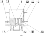
- valve body 11: water inlet; 12: water outlet; 13: drainage opening; 14: first filter element interface; 15: second filter element interface; 151: spacing beam; 152: first filter element water outlet interface; 153: second filter element water outlet interface; 16: third filter element interface; 17: fourth filter element interface; 2: movable valve plate; 21: limber hole; 22: first groove; 221: first blind slot; 222: second blind slot; 223: third blind slot; 23: second groove; 24: third groove; 25: second blind plate; 26: first spacing beam; 27: second spacing beam; 3: fixed valve plate; 31: first through hole; 32: second through hole; 321: first water outlet through hole; 322: second water outlet through hole; 33: third through hole; 34: fourth through hole; and 35: first blind plate.
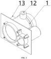
- a multifunctional water treatment filter valve includes a valve body 1, a movable valve plate 2, a fixed valve plate 3, and a driving device.
- the fixed valve plate 3 is fixedly mounted in the valve body 1.
- the movable valve plate 2 and the fixed valve plate 3 are in rotatable fit in the valve body 1.
- a side wall of the valve body 1 is provided with a water inlet 11, a water outlet 12 and a drainage opening 13.
- the driving device drives the movable valve plate 2 and the fixed valve plate 3 to cooperate with each other to achieve functions of running, back flushing and forward flushing.
- a first through hole 31, a second through hole 32, and a third through hole 33 are formed in the fixed valve plate 3 in sequence along a circumferential direction.
- the first through hole 31, the second through hole 32 and the third through hole 33 are all of arc fan-shaped structures and are arranged along the same central axis.
- a fourth through hole 34 is formed in a center of the fixed valve plate 3.
- the second through hole 32 includes a first water outlet through hole 321 and a second water outlet through hole 322 which are spaced from each other and are both arc fan-shaped.
- the first water outlet through hole 321 and the second water outlet through hole 322 are arranged along the same central axis.
- the first water outlet through hole 321 is located at a position, close to the axis, on an inner side of the second water outlet through hole 322.
- the valve body 1 includes a first filter element interface 14, a second filter element interface 15, and a third filter element interface 16.
- the first filter element interface 14, the second filter element interface 15 and the third filter element interface 16 are respectively communicated with the first through hole 31, the second through hole 32 and the third through hole 33.
- the drainage opening 13 is L-shaped, a vertical section of which is arranged in a center position of the valve body 1 and a horizontal section of which extends out of the side wall of the valve body 1.
- the fourth through hole 34 sleeves a top of the drainage opening 13.
- the second filter element interface 15 includes a spacing beam 151, and a first filter element water outlet interface 152 and a second filter element water outlet interface 153 which are spaced by the separation beam 151.
- Positions of the first filter element water outlet interface 152 and the second filter element water outlet interface 153 respectively correspond to the first water outlet through hole 321 and the second water outlet through hole 322 and are respectively correspondingly communicated.
- a fourth filter element interface 17 is arranged at a center position of a lower end of the valve body 1. The fourth filter element interface 17 is communicated with the second filter element interface 152 on the second filter element interface 15.
- the first groove 22 and the second groove 23 are both arc fan-shaped.
- a third groove 24 is formed in a center position of the movable valve plate 2.
- the first groove 22 includes a first blind slot 221, a second blind slot 222, and a third blind slot 223 which are spaced from each other and are arranged along the same central axis.
- the first blind slot 221 is arranged on an outer side of the second blind slot 222.
- the third blind slot 223 is arranged on an inner side of the second blind slot 222.
- a first spacing beam 26 is arranged between the first blind slot 221 and the second blind slot 222.
- a second spacing beam 27 is arranged between the second blind slot 222 and the third blind slot 223.
- the third blind slot 223 is communicated with the third groove 24.
- a running process of the multifunctional water treatment filter valve includes a normal running mode, a forward flushing mode and a back flushing mode.
- the driving device drives the movable valve plate 2 to rotate to different positions to switch the filter valve among different running processes.
- a specific process is as follows: As shown in FIG. 8 to FIG. 9 , in the normal running process, the limber hole 21 is communicated with the first through hole 31.
- the second groove 23 is communicated with the first water outlet through hole 321 and the second water outlet through hole 322.
- the third groove 24 and the third through hole 33 are correspondingly blocked.
- the working process is as follows: Water enters the valve body 1 from the water inlet 11, and enters a tank body at a lower end of the valve body 1 through the limber hole 21 and the first through hole 31 in sequence; and water flow then enters the second groove 23 through the fourth filter element interface 17, the first filter element water outlet interface 152 in the second filter element interface 15, and the first water outlet through hole 321, enters the second water outlet through hole 322 through the second groove 23, and is discharged from the water outlet 12, thus achieving normal running of the filter valve.
- the limber hole 21 is communicated with the first water outlet through hole 321.
- Water to the second water outlet through hole 322 is cut off.
- the first through hole 31 is communicated with the third groove 24 through the third blind slot 223.
- the third groove 24 is communicated with the drainage opening 13.
- the working process is as follows: Water enters the first water outlet through hole 321 via the limber hole 21.
- the second water outlet through hole 322 is blocked by the second blind plate 25 on the movable valve plate 2.
- the water flow enters the tank body at the lower end of the valve body 1 through the first filter element water outlet interface 152 in the second filter element interface 15 and the fourth filter element interface 17.
- the water arrives at the first filter element interface 14 from the filter element layer.
- Wastewater generated by back flushing arrives at the first through hole 31 through the first filter element interface 14, arrives at the fourth through hole 34 through the third blind slot 223 and the third groove 24, and is discharged from the drainage opening 13.
- the third through hole 33 is covered by the second groove 23 to cut off the water flow and form a sealed space.
- the limber hole 21 is communicated with the third through hole 33.
- the first water outlet thorough hole 321 is communicated with the third groove 24 through the third blind slot 223.
- the third groove 24 is communicated with the drainage opening 13 through the fourth through hole 34.
- the second water outlet through hole 322 is blocked by the first spacing beam 26 on the movable valve plate 2 to cut off the water.
- the working process is as follows: The water flow enters the valve body 1 from the water inlet 11, and enters the filter layer of the filter element of the tank body at the lower end of the valve body 1 through the limber hole 21 and the third through hole 33 in sequence.
- the water arrives at the first filter element water outlet interface 152 in the second filter element interface 15 through the fourth filter element interface 17, enters the third blind slot 223 through the first water outlet through hole 321, and enters the third groove 24 through the third blind slot 223.
- the water flow is finally discharged from the drainage opening 13 connected to the fourth through hole 34, thus achieving the forward flushing process of the filter valve.
- the first through hole 31 and the second groove 23 are matched to form a closed space
- the second water outlet through hole 322 and the first blind slot 221 are matched to form a closed space to prevent the water from being discharged from the water outlet 12.
- the positions of the first filter element interface 14, the second filter element interface 15, and the third filter element interface 16 respectively correspond to the positions of the first through hole 31, the second through hole 32, and the third through hole 33 on a one-to-one basis.
- each of the first through hole 31, the second through hole 32 and the third through hole 33 has a central angle of 120 degrees
- each of the limber hole 21, the first groove 22 and the second groove 23 has a central angle of 120 degrees
- the first through hole 31, the second through hole 32 and the third through hole 33 are arranged in a trisection manner to achieve a water inlet and outlet effective use area of the fixed valve plate 3, and the limber hole, the first groove 22 and the second groove 23 are also arranged in a trisection manner, so that cooperation between the movable valve plate 2 and the fixed valve plate 3 can be better achieved.
- a first blind plate 35 is arranged on an inner side of the third through hole 33 on the fixed valve plate 3; and the first blind plate 35 separates the third through hole 33 from the fourth through hole 34.
- the limber hole 21 is perforated along an axial direction of the movable valve plate 2; the limber hole 21 is of a ring fan-shaped structure; and an outer side of the limber hole 21 along a radial direction of the movable valve plate 2 is provided with a second blind plate 25.
- the limber hole 21 is perforated from top to bottom, so that the structure is simpler, and machining and production are easier.
Landscapes
- Engineering & Computer Science (AREA)
- General Engineering & Computer Science (AREA)
- Chemical & Material Sciences (AREA)
- Chemical Kinetics & Catalysis (AREA)
- Mechanical Engineering (AREA)
- Multiple-Way Valves (AREA)
Claims (4)
- Ein multifunktionales Wasseraufbereitungsfilterventil, umfassend einen Ventilkörper (1), eine bewegliche Ventilplatte (2), eine feststehende Ventilplatte (3) und eine Antriebsvorrichtung; wobei die feststehende Ventilplatte (3) fest im Ventilkörper (1) montiert ist; die bewegliche Ventilplatte (2) und die feststehende Ventilplatte (3) drehbar im Ventilkörper (1) eingepasst sind; eine Seitenwand des Ventilkörpers (1) mit einem Wassereinlass (11), einem Wasserauslass (12), und einer Abflussöffnung (13) versehen ist; die Antriebsvorrichtung so konfiguriert ist, dass sie die bewegliche Ventilplatte (2) und die feststehende Ventilplatte (3) so antreibt, dass sie miteinander zusammenwirken, damit das multifunktionale Wasseraufbereitungsfilterventil in einem normalen Betriebsprozess, einem Rückspülmodus, oder einem Vorwärtsspülmodus arbeitet; dadurch gekennzeichnet, dassein erstes Durchgangsloch (31), ein zweites Durchgangsloch (32), und ein drittes Durchgangsloch (33) in der feststehenden Ventilplatte (3) in einer Abfolge entlang einer Umfangsrichtung ausgebildet sind; das erste Durchgangsloch (31), das zweite Durchgangsloch (32), und das dritte Durchgangsloch (33) alle bogenfächerförmige Strukturen aufweisen und entlang derselben Mittelachse angeordnet sind; ein viertes Durchgangsloch (34) in einer Mitte der feststehenden Ventilplatte (3) ausgebildet ist; das zweite Durchgangsloch (32) ein erstes Wasserauslass-Durchgangsloch (321) und ein zweites Wasserauslass-Durchgangsloch (322) umfasst, die voneinander beabstandet sind und beide bogenfächerförmig sind; das erste Wasserauslass-Durchgangsloch (321) und das zweite Wasserauslass-Durchgangsloch (322) entlang derselben Mittelachse angeordnet sind; das erste Wasserauslass-Durchgangsloch (321) sich an einer Position nahe der Achse, auf einer Innenseite des zweiten Wasserauslass-Durchgangslochs (322) befindet;der Ventilkörper (1) eine erste Filterelement-Schnittstelle (14), eine zweite Filterelement-Schnittstelle (15), und eine dritte Filterelement-Schnittstelle (16) umfasst; die erste Filterelement-Schnittstelle (14), die zweite Filterelement-Schnittstelle (15), und die dritte Filterelement-Schnittstelle (16) jeweils mit dem ersten Durchgangsloch (31), dem zweiten Durchgangsloch (32), und dem dritten Durchgangsloch (33) in Verbindung stehen; die Abflussöffnung (13) L-förmig ist, wobei ein vertikaler Abschnitt davon in einer Mittelposition des Ventilkörpers (1) angeordnet ist und ein horizontaler Abschnitt davon sich aus der Seitenwand des Ventilkörpers (1) heraus erstreckt; das vierte Durchgangsloch (34) eine Oberseite der Abflussöffnung (13) umhüllt; die zweite Filterelement-Schnittstelle (15) einen Abstandsträger (151), und eine erste Filterelement-Wasserauslassschnittstelle (152) und eine zweite Filterelement-Wasserauslassschnittstelle (153), die durch den Abstandsträger (151) voneinander beabstandet sind; Positionen der ersten Filterelement-Wasserauslassschnittstelle (152) und der zweiten Filterelement-Wasserauslassschnittstelle (153) jeweils dem ersten Wasserauslass-Durchgangsloch (321) und dem zweiten Wasserauslass-Durchgangsloch (322) entsprechen und entsprechend miteinander in Verbindung stehen; eine vierte Filterelement-Schnittstelle (17) an einer Mittelposition eines unteren Endes des Ventilkörpers (1) angeordnet ist; die vierte Filterelement-Schnittstelle (17) mit der zweiten Filterelement-Schnittstelle (15) in Verbindung steht;ein mit dem Wassereinlass (11) in Verbindung stehendes Entlastungsloch (21), und eine erste Nut (22) und eine zweite Nut (23) in der beweglichen Ventilplatte (2) entlang der Umfangsrichtung ausgebildet sind; die erste Nut (22) und die zweite Nut (23) beide bogenfächerförmig sind; eine dritte Nut (24) in einer Mittelposition der beweglichen Ventilplatte (2) ausgebildet ist; die erste Nut (22) einen ersten Blindschlitz (221), einen zweiten Blindschlitz (222), und einen dritten Blindschlitz (223) umfasst, die voneinander beabstandet sind und entlang derselben Mittelachse angeordnet sind; der erste Blindschlitz (221) an einer Außenseite des zweiten Blindschlitzes (222) angeordnet ist; der dritte Blindschlitz (223) an einer Innenseite des zweiten Blindschlitzes (222) angeordnet ist; ein erster Abstandhalter (26) zwischen dem ersten Blindschlitz (221) und dem zweiten Blindschlitz (222) angeordnet ist; ein zweiter Abstandhalter (27) zwischen dem zweiten Blindschlitz (222) und dem dritten Blindschlitz (223) angeordnet ist; und der dritte Blindschlitz (223) mit der dritten Nut (24) in Verbindung steht;Positionen der ersten Filterelement-Schnittstelle (14), der zweiten Filterelement-Schnittstelle (15), und der dritten Filterelement-Schnittstelle (16) jeweils Positionen des ersten Durchgangslochs (31), des zweiten Durchgangslochs (32), und des dritten Durchgangsloch (33) auf einer Eins-zu-Eins-Basis entsprechen;im normalen Betriebsprozess ist das Entlastungsloch (21) mit dem ersten Durchgangsloch (31) verbunden, und die zweite Nut (23) mit dem ersten Wasserauslass-Durchgangsloch (321) und dem zweiten Wasserauslass-Durchgangsloch (322) verbunden ist, und die dritte Nut (24) und das dritte Durchgangsloch (33) entsprechend blockiert sind;im Rückspülmodus ist das Entlastungsloch (21) mit dem ersten Wasserauslass-Durchgangsloch (321) verbunden, Wasser zum zweiten Wasserauslass-Durchgangsloch (322) unterbrochen wird und das erste Durchgangsloch (31) mit der dritten Nut (24) durch den dritten Blindschlitz (223) verbunden ist, und die dritte Nut (24) mit der Abflussöffnung (13) verbunden ist; undim Vorwärtsspülmodus ist das Entlastungsloch (21) mit dem dritten Durchgangsloch (33) verbunden, das erste Wasserauslass-Durchgangsloch (321) mit der dritten Nut (24) durch den dritten Blindschlitz (223) verbunden ist, die dritte Nut (24) mit der Abflussöffnung (13) durch das vierte Durchgangsloch (34) verbunden ist, und das zweite Wasserauslass-Durchgangsloch (322) durch den ersten Abstandshalter (26) auf der beweglichen Ventilplatte (2) blockiert ist, um das Wasser abzusperren.
- Das multifunktionale Wasseraufbereitungsfilterventil nach Anspruch 1, wobei jedes des ersten Durchgangslochs (31), des zweiten Durchgangslochs (32), und des dritten Durchgangslochs (33) einen Zentriwinkel von 120 Grad aufweist, und jede des Entlastungslochs (21), der ersten Nut (22), und der zweiten Nut (23) einen Zentriwinkel von 120 Grad aufweist.
- Das multifunktionale Wasseraufbereitungsfilterventil nach Anspruch 1, wobei eine erste Blindplatte (35) auf einer Innenseite des dritten Durchgangslochs (33) auf der feststehenden Ventilplatte (3) angeordnet ist; und die erste Blindplatte (35) das dritte Durchgangsloch (33) vom vierten Durchgangsloch (34) trennt.
- Das multifunktionale Wasseraufbereitungsfilterventil nach Anspruch 1, wobei das Entlastungsloch (21) entlang einer axialen Richtung der beweglichen Ventilplatte (2) perforiert ist; das Entlastungsloch (21) eine ringförmige, fächerförmige Struktur aufweist; und eine Außenseite des Entlastungslochs (21) entlang einer radialen Richtung der beweglichen Ventilplatte (2) mit einer zweiten Blindplatte (25) versehen ist.
Applications Claiming Priority (1)
| Application Number | Priority Date | Filing Date | Title |
|---|---|---|---|
| CN202210249502.2A CN114517842B (zh) | 2022-03-14 | 2022-03-14 | 一种水处理多功能过滤阀 |
Publications (2)
| Publication Number | Publication Date |
|---|---|
| EP4245396A1 EP4245396A1 (de) | 2023-09-20 |
| EP4245396B1 true EP4245396B1 (de) | 2024-11-06 |
Family
ID=81599520
Family Applications (1)
| Application Number | Title | Priority Date | Filing Date |
|---|---|---|---|
| EP23156699.3A Active EP4245396B1 (de) | 2022-03-14 | 2023-02-15 | Multifunktionales filterventil zur wasserbehandlung |
Country Status (3)
| Country | Link |
|---|---|
| US (1) | US12357929B2 (de) |
| EP (1) | EP4245396B1 (de) |
| CN (1) | CN114517842B (de) |
Families Citing this family (2)
| Publication number | Priority date | Publication date | Assignee | Title |
|---|---|---|---|---|
| EP4435243A4 (de) * | 2022-10-17 | 2025-01-15 | Johnson Electric International AG | Wärmeverwaltungssystem und ventil dafür |
| WO2025179950A1 (zh) * | 2024-02-29 | 2025-09-04 | 佛山市顺德区美的饮水机制造有限公司 | 控制阀及软水机 |
Family Cites Families (18)
| Publication number | Priority date | Publication date | Assignee | Title |
|---|---|---|---|---|
| US5328609A (en) * | 1992-11-16 | 1994-07-12 | Magnusson Jon H | Multi-stage radial flow filtration system |
| US5525214A (en) | 1994-03-08 | 1996-06-11 | Recovery Engineering, Inc. | Filter cartridge for water treatment device |
| US5814130A (en) * | 1996-09-27 | 1998-09-29 | The Boc Group, Inc. | Process and apparatus for gas separation |
| US6012476A (en) * | 1999-01-26 | 2000-01-11 | Chung-Cheng Faucet Co., Ltd. | Pressure balancer for use in a water inlet passage of a mixing faucet |
| CN2573049Y (zh) * | 2002-10-11 | 2003-09-17 | 杨润德 | 净水器过滤管路装置 |
| CN2623678Y (zh) * | 2003-05-23 | 2004-07-07 | 温州市润新机械制造有限公司 | 多功能单阀控制净水器 |
| MX2007000110A (es) * | 2004-07-17 | 2007-03-09 | Runde Yang | Valvula de control de flujo multifuncional para sistemas de tratamiento de agua. |
| WO2013155879A1 (zh) * | 2012-04-19 | 2013-10-24 | Hu Xiaozong | 控流器及具有该控流器的水处理系统 |
| WO2014088739A1 (en) | 2012-11-01 | 2014-06-12 | Harris Charles E C | Side filter ozone water treatment apparatus |
| CN104593992A (zh) * | 2013-10-30 | 2015-05-06 | 海尔集团公司 | 一种波轮式热泵洗干一体机及烘干方法 |
| ES2844587T3 (es) * | 2014-01-20 | 2021-07-22 | Wenzhou Runxin Mfg Machine Co Ltd | Válvula de control |
| CN205064928U (zh) * | 2015-09-25 | 2016-03-02 | 厦门建霖工业有限公司 | 中央净水器控制阀 |
| CN105179745B (zh) * | 2015-10-06 | 2017-10-31 | 龙口诚峰智远科技有限公司 | 一种固定床顺流再生阀及其水处理装置 |
| KR20180076768A (ko) | 2016-12-28 | 2018-07-06 | 엘지전자 주식회사 | 수처리 장치용 필터 및 이를 포함하는 수처리 장치 |
| CN207178747U (zh) * | 2017-06-06 | 2018-04-03 | 温州市润新机械制造有限公司 | 一种带关闭功能的水处理过滤阀 |
| CN110056676A (zh) * | 2019-02-01 | 2019-07-26 | 厦门水芯科技有限公司 | 一种带流量控制的单把手恒温阀芯及出水龙头 |
| CN212356761U (zh) * | 2019-07-18 | 2021-01-15 | 余姚市亚东塑业有限公司 | 龙头净水器 |
| CN216895920U (zh) * | 2022-03-14 | 2022-07-05 | 河南滨润水处理科技有限公司 | 一种水处理多功能过滤阀 |
-
2022
- 2022-03-14 CN CN202210249502.2A patent/CN114517842B/zh active Active
- 2022-10-14 US US17/965,804 patent/US12357929B2/en active Active
-
2023
- 2023-02-15 EP EP23156699.3A patent/EP4245396B1/de active Active
Also Published As
| Publication number | Publication date |
|---|---|
| CN114517842A (zh) | 2022-05-20 |
| US20230311032A1 (en) | 2023-10-05 |
| US12357929B2 (en) | 2025-07-15 |
| CN114517842B (zh) | 2025-01-10 |
| EP4245396A1 (de) | 2023-09-20 |
Similar Documents
| Publication | Publication Date | Title |
|---|---|---|
| AU2005263257B2 (en) | A multifunction control valve for a water treatment system | |
| CN114100230B (zh) | 一种水处理过滤系统及多路阀 | |
| CN111140671B (zh) | 一种多功能流体控制阀及其水处理装置 | |
| EP3733258B1 (de) | Filteranordnung, die zur beseitigung von feststoffen unter verwendung eines strömungsvariablen bypass-strömungswegs fähig ist | |
| EP4245396A1 (de) | Multifunktionales filterventil zur wasserbehandlung | |
| CN213012250U (zh) | 净水器及用于净水器的控制阀 | |
| CN115183015B (zh) | 一种水处理用多功能过滤阀 | |
| US12565936B2 (en) | Multifunctional filter valve | |
| CN117803731A (zh) | 一种水处理过滤设备 | |
| CN222067677U (zh) | 水处理过水结构及水处理装置 | |
| WO2025218266A1 (zh) | 一种水处理过水结构及水处理装置 | |
| CN219299991U (zh) | 多功能过滤阀 | |
| CN116658641B (zh) | 一种水处理多功能过滤阀 | |
| CN215855150U (zh) | 龙头净水器 | |
| CN221097552U (zh) | 一种不间断供水的水处理多功能控制阀结构 | |
| WO2024109578A1 (zh) | 一种多功能过滤阀 | |
| CN214889017U (zh) | 一种防堵塞衬氟球阀 | |
| CN113149134B (zh) | 滤头、过滤器以及过滤机组 | |
| US20220331717A1 (en) | Filter assembly capable of adjusting elimination of solid materials using flow-variable bypass flow path | |
| CN210461785U (zh) | 一种超滤多路阀头 | |
| CN211779149U (zh) | 一种多功能流体控制阀及其水处理装置 | |
| CN222122318U (zh) | 水处理机和用于水处理机的控制阀 | |
| CN224107707U (zh) | 一种水处理多功能多路阀 | |
| CN218811214U (zh) | 净水系统 | |
| JP2001355749A (ja) | 五方切換弁および濾過装置 |
Legal Events
| Date | Code | Title | Description |
|---|---|---|---|
| PUAI | Public reference made under article 153(3) epc to a published international application that has entered the european phase |
Free format text: ORIGINAL CODE: 0009012 |
|
| STAA | Information on the status of an ep patent application or granted ep patent |
Free format text: STATUS: REQUEST FOR EXAMINATION WAS MADE |
|
| 17P | Request for examination filed |
Effective date: 20230215 |
|
| AK | Designated contracting states |
Kind code of ref document: A1 Designated state(s): AL AT BE BG CH CY CZ DE DK EE ES FI FR GB GR HR HU IE IS IT LI LT LU LV MC ME MK MT NL NO PL PT RO RS SE SI SK SM TR |
|
| GRAP | Despatch of communication of intention to grant a patent |
Free format text: ORIGINAL CODE: EPIDOSNIGR1 |
|
| STAA | Information on the status of an ep patent application or granted ep patent |
Free format text: STATUS: GRANT OF PATENT IS INTENDED |
|
| INTG | Intention to grant announced |
Effective date: 20240606 |
|
| GRAS | Grant fee paid |
Free format text: ORIGINAL CODE: EPIDOSNIGR3 |
|
| GRAA | (expected) grant |
Free format text: ORIGINAL CODE: 0009210 |
|
| STAA | Information on the status of an ep patent application or granted ep patent |
Free format text: STATUS: THE PATENT HAS BEEN GRANTED |
|
| AK | Designated contracting states |
Kind code of ref document: B1 Designated state(s): AL AT BE BG CH CY CZ DE DK EE ES FI FR GB GR HR HU IE IS IT LI LT LU LV MC ME MK MT NL NO PL PT RO RS SE SI SK SM TR |
|
| REG | Reference to a national code |
Ref country code: GB Ref legal event code: FG4D |
|
| REG | Reference to a national code |
Ref country code: CH Ref legal event code: EP |
|
| REG | Reference to a national code |
Ref country code: DE Ref legal event code: R096 Ref document number: 602023000902 Country of ref document: DE |
|
| REG | Reference to a national code |
Ref country code: IE Ref legal event code: FG4D |
|
| REG | Reference to a national code |
Ref country code: LT Ref legal event code: MG9D |
|
| REG | Reference to a national code |
Ref country code: NL Ref legal event code: MP Effective date: 20241106 |
|
| PG25 | Lapsed in a contracting state [announced via postgrant information from national office to epo] |
Ref country code: HR Free format text: LAPSE BECAUSE OF FAILURE TO SUBMIT A TRANSLATION OF THE DESCRIPTION OR TO PAY THE FEE WITHIN THE PRESCRIBED TIME-LIMIT Effective date: 20241106 Ref country code: IS Free format text: LAPSE BECAUSE OF FAILURE TO SUBMIT A TRANSLATION OF THE DESCRIPTION OR TO PAY THE FEE WITHIN THE PRESCRIBED TIME-LIMIT Effective date: 20250306 Ref country code: PT Free format text: LAPSE BECAUSE OF FAILURE TO SUBMIT A TRANSLATION OF THE DESCRIPTION OR TO PAY THE FEE WITHIN THE PRESCRIBED TIME-LIMIT Effective date: 20250306 |
|
| PG25 | Lapsed in a contracting state [announced via postgrant information from national office to epo] |
Ref country code: NL Free format text: LAPSE BECAUSE OF FAILURE TO SUBMIT A TRANSLATION OF THE DESCRIPTION OR TO PAY THE FEE WITHIN THE PRESCRIBED TIME-LIMIT Effective date: 20241106 Ref country code: FI Free format text: LAPSE BECAUSE OF FAILURE TO SUBMIT A TRANSLATION OF THE DESCRIPTION OR TO PAY THE FEE WITHIN THE PRESCRIBED TIME-LIMIT Effective date: 20241106 |
|
| REG | Reference to a national code |
Ref country code: AT Ref legal event code: MK05 Ref document number: 1738750 Country of ref document: AT Kind code of ref document: T Effective date: 20241106 |
|
| PG25 | Lapsed in a contracting state [announced via postgrant information from national office to epo] |
Ref country code: BG Free format text: LAPSE BECAUSE OF FAILURE TO SUBMIT A TRANSLATION OF THE DESCRIPTION OR TO PAY THE FEE WITHIN THE PRESCRIBED TIME-LIMIT Effective date: 20241106 |
|
| PG25 | Lapsed in a contracting state [announced via postgrant information from national office to epo] |
Ref country code: ES Free format text: LAPSE BECAUSE OF FAILURE TO SUBMIT A TRANSLATION OF THE DESCRIPTION OR TO PAY THE FEE WITHIN THE PRESCRIBED TIME-LIMIT Effective date: 20241106 |
|
| PG25 | Lapsed in a contracting state [announced via postgrant information from national office to epo] |
Ref country code: NO Free format text: LAPSE BECAUSE OF FAILURE TO SUBMIT A TRANSLATION OF THE DESCRIPTION OR TO PAY THE FEE WITHIN THE PRESCRIBED TIME-LIMIT Effective date: 20250206 |
|
| PG25 | Lapsed in a contracting state [announced via postgrant information from national office to epo] |
Ref country code: GR Free format text: LAPSE BECAUSE OF FAILURE TO SUBMIT A TRANSLATION OF THE DESCRIPTION OR TO PAY THE FEE WITHIN THE PRESCRIBED TIME-LIMIT Effective date: 20250207 Ref country code: LV Free format text: LAPSE BECAUSE OF FAILURE TO SUBMIT A TRANSLATION OF THE DESCRIPTION OR TO PAY THE FEE WITHIN THE PRESCRIBED TIME-LIMIT Effective date: 20241106 Ref country code: AT Free format text: LAPSE BECAUSE OF FAILURE TO SUBMIT A TRANSLATION OF THE DESCRIPTION OR TO PAY THE FEE WITHIN THE PRESCRIBED TIME-LIMIT Effective date: 20241106 |
|
| PG25 | Lapsed in a contracting state [announced via postgrant information from national office to epo] |
Ref country code: PL Free format text: LAPSE BECAUSE OF FAILURE TO SUBMIT A TRANSLATION OF THE DESCRIPTION OR TO PAY THE FEE WITHIN THE PRESCRIBED TIME-LIMIT Effective date: 20241106 |
|
| PG25 | Lapsed in a contracting state [announced via postgrant information from national office to epo] |
Ref country code: RS Free format text: LAPSE BECAUSE OF FAILURE TO SUBMIT A TRANSLATION OF THE DESCRIPTION OR TO PAY THE FEE WITHIN THE PRESCRIBED TIME-LIMIT Effective date: 20250206 |
|
| PG25 | Lapsed in a contracting state [announced via postgrant information from national office to epo] |
Ref country code: SM Free format text: LAPSE BECAUSE OF FAILURE TO SUBMIT A TRANSLATION OF THE DESCRIPTION OR TO PAY THE FEE WITHIN THE PRESCRIBED TIME-LIMIT Effective date: 20241106 |
|
| PG25 | Lapsed in a contracting state [announced via postgrant information from national office to epo] |
Ref country code: DK Free format text: LAPSE BECAUSE OF FAILURE TO SUBMIT A TRANSLATION OF THE DESCRIPTION OR TO PAY THE FEE WITHIN THE PRESCRIBED TIME-LIMIT Effective date: 20241106 |
|
| PG25 | Lapsed in a contracting state [announced via postgrant information from national office to epo] |
Ref country code: EE Free format text: LAPSE BECAUSE OF FAILURE TO SUBMIT A TRANSLATION OF THE DESCRIPTION OR TO PAY THE FEE WITHIN THE PRESCRIBED TIME-LIMIT Effective date: 20241106 |
|
| PG25 | Lapsed in a contracting state [announced via postgrant information from national office to epo] |
Ref country code: RO Free format text: LAPSE BECAUSE OF FAILURE TO SUBMIT A TRANSLATION OF THE DESCRIPTION OR TO PAY THE FEE WITHIN THE PRESCRIBED TIME-LIMIT Effective date: 20241106 |
|
| PG25 | Lapsed in a contracting state [announced via postgrant information from national office to epo] |
Ref country code: SK Free format text: LAPSE BECAUSE OF FAILURE TO SUBMIT A TRANSLATION OF THE DESCRIPTION OR TO PAY THE FEE WITHIN THE PRESCRIBED TIME-LIMIT Effective date: 20241106 |
|
| PG25 | Lapsed in a contracting state [announced via postgrant information from national office to epo] |
Ref country code: CZ Free format text: LAPSE BECAUSE OF FAILURE TO SUBMIT A TRANSLATION OF THE DESCRIPTION OR TO PAY THE FEE WITHIN THE PRESCRIBED TIME-LIMIT Effective date: 20241106 |
|
| PG25 | Lapsed in a contracting state [announced via postgrant information from national office to epo] |
Ref country code: IT Free format text: LAPSE BECAUSE OF FAILURE TO SUBMIT A TRANSLATION OF THE DESCRIPTION OR TO PAY THE FEE WITHIN THE PRESCRIBED TIME-LIMIT Effective date: 20241106 |
|
| REG | Reference to a national code |
Ref country code: DE Ref legal event code: R097 Ref document number: 602023000902 Country of ref document: DE |
|
| PG25 | Lapsed in a contracting state [announced via postgrant information from national office to epo] |
Ref country code: SE Free format text: LAPSE BECAUSE OF FAILURE TO SUBMIT A TRANSLATION OF THE DESCRIPTION OR TO PAY THE FEE WITHIN THE PRESCRIBED TIME-LIMIT Effective date: 20241106 |
|
| PLBE | No opposition filed within time limit |
Free format text: ORIGINAL CODE: 0009261 |
|
| STAA | Information on the status of an ep patent application or granted ep patent |
Free format text: STATUS: NO OPPOSITION FILED WITHIN TIME LIMIT |
|
| PG25 | Lapsed in a contracting state [announced via postgrant information from national office to epo] |
Ref country code: MC Free format text: LAPSE BECAUSE OF FAILURE TO SUBMIT A TRANSLATION OF THE DESCRIPTION OR TO PAY THE FEE WITHIN THE PRESCRIBED TIME-LIMIT Effective date: 20241106 |
|
| 26N | No opposition filed |
Effective date: 20250807 |
|
| PG25 | Lapsed in a contracting state [announced via postgrant information from national office to epo] |
Ref country code: LU Free format text: LAPSE BECAUSE OF NON-PAYMENT OF DUE FEES Effective date: 20250215 |
|
| REG | Reference to a national code |
Ref country code: BE Ref legal event code: MM Effective date: 20250228 |
|
| PG25 | Lapsed in a contracting state [announced via postgrant information from national office to epo] |
Ref country code: BE Free format text: LAPSE BECAUSE OF NON-PAYMENT OF DUE FEES Effective date: 20250228 |
|
| PG25 | Lapsed in a contracting state [announced via postgrant information from national office to epo] |
Ref country code: IE Free format text: LAPSE BECAUSE OF NON-PAYMENT OF DUE FEES Effective date: 20250215 |
|
| PGFP | Annual fee paid to national office [announced via postgrant information from national office to epo] |
Ref country code: DE Payment date: 20260212 Year of fee payment: 4 |
|
| PGFP | Annual fee paid to national office [announced via postgrant information from national office to epo] |
Ref country code: FR Payment date: 20260213 Year of fee payment: 4 |