EP4245275A1 - Apparatus and method for ultrasonic welding - Google Patents
Apparatus and method for ultrasonic welding Download PDFInfo
- Publication number
- EP4245275A1 EP4245275A1 EP21891564.3A EP21891564A EP4245275A1 EP 4245275 A1 EP4245275 A1 EP 4245275A1 EP 21891564 A EP21891564 A EP 21891564A EP 4245275 A1 EP4245275 A1 EP 4245275A1
- Authority
- EP
- European Patent Office
- Prior art keywords
- anvil
- web
- horn
- conveying drum
- ultrasonic
- Prior art date
- Legal status (The legal status is an assumption and is not a legal conclusion. Google has not performed a legal analysis and makes no representation as to the accuracy of the status listed.)
- Pending
Links
Images



Classifications
-
- B—PERFORMING OPERATIONS; TRANSPORTING
- B29—WORKING OF PLASTICS; WORKING OF SUBSTANCES IN A PLASTIC STATE IN GENERAL
- B29C—SHAPING OR JOINING OF PLASTICS; SHAPING OF MATERIAL IN A PLASTIC STATE, NOT OTHERWISE PROVIDED FOR; AFTER-TREATMENT OF THE SHAPED PRODUCTS, e.g. REPAIRING
- B29C65/00—Joining or sealing of preformed parts, e.g. welding of plastics materials; Apparatus therefor
- B29C65/02—Joining or sealing of preformed parts, e.g. welding of plastics materials; Apparatus therefor by heating, with or without pressure
- B29C65/08—Joining or sealing of preformed parts, e.g. welding of plastics materials; Apparatus therefor by heating, with or without pressure using ultrasonic vibrations
-
- B—PERFORMING OPERATIONS; TRANSPORTING
- B29—WORKING OF PLASTICS; WORKING OF SUBSTANCES IN A PLASTIC STATE IN GENERAL
- B29C—SHAPING OR JOINING OF PLASTICS; SHAPING OF MATERIAL IN A PLASTIC STATE, NOT OTHERWISE PROVIDED FOR; AFTER-TREATMENT OF THE SHAPED PRODUCTS, e.g. REPAIRING
- B29C65/00—Joining or sealing of preformed parts, e.g. welding of plastics materials; Apparatus therefor
- B29C65/02—Joining or sealing of preformed parts, e.g. welding of plastics materials; Apparatus therefor by heating, with or without pressure
- B29C65/08—Joining or sealing of preformed parts, e.g. welding of plastics materials; Apparatus therefor by heating, with or without pressure using ultrasonic vibrations
- B29C65/083—Joining or sealing of preformed parts, e.g. welding of plastics materials; Apparatus therefor by heating, with or without pressure using ultrasonic vibrations using a rotary sonotrode or a rotary anvil
- B29C65/086—Joining or sealing of preformed parts, e.g. welding of plastics materials; Apparatus therefor by heating, with or without pressure using ultrasonic vibrations using a rotary sonotrode or a rotary anvil using a rotary anvil
-
- A—HUMAN NECESSITIES
- A61—MEDICAL OR VETERINARY SCIENCE; HYGIENE
- A61F—FILTERS IMPLANTABLE INTO BLOOD VESSELS; PROSTHESES; DEVICES PROVIDING PATENCY TO, OR PREVENTING COLLAPSING OF, TUBULAR STRUCTURES OF THE BODY, e.g. STENTS; ORTHOPAEDIC, NURSING OR CONTRACEPTIVE DEVICES; FOMENTATION; TREATMENT OR PROTECTION OF EYES OR EARS; BANDAGES, DRESSINGS OR ABSORBENT PADS; FIRST-AID KITS
- A61F13/00—Bandages or dressings; Absorbent pads
- A61F13/15—Absorbent pads, e.g. sanitary towels, swabs or tampons for external or internal application to the body; Supporting or fastening means therefor; Tampon applicators
- A61F13/15577—Apparatus or processes for manufacturing
- A61F13/15699—Forming webs by bringing together several webs, e.g. by laminating or folding several webs, with or without additional treatment of the webs
-
- A—HUMAN NECESSITIES
- A61—MEDICAL OR VETERINARY SCIENCE; HYGIENE
- A61F—FILTERS IMPLANTABLE INTO BLOOD VESSELS; PROSTHESES; DEVICES PROVIDING PATENCY TO, OR PREVENTING COLLAPSING OF, TUBULAR STRUCTURES OF THE BODY, e.g. STENTS; ORTHOPAEDIC, NURSING OR CONTRACEPTIVE DEVICES; FOMENTATION; TREATMENT OR PROTECTION OF EYES OR EARS; BANDAGES, DRESSINGS OR ABSORBENT PADS; FIRST-AID KITS
- A61F13/00—Bandages or dressings; Absorbent pads
- A61F13/15—Absorbent pads, e.g. sanitary towels, swabs or tampons for external or internal application to the body; Supporting or fastening means therefor; Tampon applicators
- A61F13/15577—Apparatus or processes for manufacturing
- A61F13/15707—Mechanical treatment, e.g. notching, twisting, compressing, shaping
- A61F13/15739—Sealing, e.g. involving cutting
-
- A—HUMAN NECESSITIES
- A61—MEDICAL OR VETERINARY SCIENCE; HYGIENE
- A61F—FILTERS IMPLANTABLE INTO BLOOD VESSELS; PROSTHESES; DEVICES PROVIDING PATENCY TO, OR PREVENTING COLLAPSING OF, TUBULAR STRUCTURES OF THE BODY, e.g. STENTS; ORTHOPAEDIC, NURSING OR CONTRACEPTIVE DEVICES; FOMENTATION; TREATMENT OR PROTECTION OF EYES OR EARS; BANDAGES, DRESSINGS OR ABSORBENT PADS; FIRST-AID KITS
- A61F13/00—Bandages or dressings; Absorbent pads
- A61F13/15—Absorbent pads, e.g. sanitary towels, swabs or tampons for external or internal application to the body; Supporting or fastening means therefor; Tampon applicators
- A61F13/45—Absorbent pads, e.g. sanitary towels, swabs or tampons for external or internal application to the body; Supporting or fastening means therefor; Tampon applicators characterised by the shape
- A61F13/49—Absorbent pads, e.g. sanitary towels, swabs or tampons for external or internal application to the body; Supporting or fastening means therefor; Tampon applicators characterised by the shape specially adapted to be worn around the waist, e.g. diapers, nappies
- A61F13/496—Absorbent pads, e.g. sanitary towels, swabs or tampons for external or internal application to the body; Supporting or fastening means therefor; Tampon applicators characterised by the shape specially adapted to be worn around the waist, e.g. diapers, nappies in the form of pants or briefs
-
- B—PERFORMING OPERATIONS; TRANSPORTING
- B29—WORKING OF PLASTICS; WORKING OF SUBSTANCES IN A PLASTIC STATE IN GENERAL
- B29C—SHAPING OR JOINING OF PLASTICS; SHAPING OF MATERIAL IN A PLASTIC STATE, NOT OTHERWISE PROVIDED FOR; AFTER-TREATMENT OF THE SHAPED PRODUCTS, e.g. REPAIRING
- B29C65/00—Joining or sealing of preformed parts, e.g. welding of plastics materials; Apparatus therefor
- B29C65/02—Joining or sealing of preformed parts, e.g. welding of plastics materials; Apparatus therefor by heating, with or without pressure
- B29C65/08—Joining or sealing of preformed parts, e.g. welding of plastics materials; Apparatus therefor by heating, with or without pressure using ultrasonic vibrations
- B29C65/083—Joining or sealing of preformed parts, e.g. welding of plastics materials; Apparatus therefor by heating, with or without pressure using ultrasonic vibrations using a rotary sonotrode or a rotary anvil
- B29C65/087—Joining or sealing of preformed parts, e.g. welding of plastics materials; Apparatus therefor by heating, with or without pressure using ultrasonic vibrations using a rotary sonotrode or a rotary anvil using both a rotary sonotrode and a rotary anvil
-
- B—PERFORMING OPERATIONS; TRANSPORTING
- B29—WORKING OF PLASTICS; WORKING OF SUBSTANCES IN A PLASTIC STATE IN GENERAL
- B29C—SHAPING OR JOINING OF PLASTICS; SHAPING OF MATERIAL IN A PLASTIC STATE, NOT OTHERWISE PROVIDED FOR; AFTER-TREATMENT OF THE SHAPED PRODUCTS, e.g. REPAIRING
- B29C65/00—Joining or sealing of preformed parts, e.g. welding of plastics materials; Apparatus therefor
- B29C65/78—Means for handling the parts to be joined, e.g. for making containers or hollow articles, e.g. means for handling sheets, plates, web-like materials, tubular articles, hollow articles or elements to be joined therewith; Means for discharging the joined articles from the joining apparatus
- B29C65/7858—Means for handling the parts to be joined, e.g. for making containers or hollow articles, e.g. means for handling sheets, plates, web-like materials, tubular articles, hollow articles or elements to be joined therewith; Means for discharging the joined articles from the joining apparatus characterised by the feeding movement of the parts to be joined
- B29C65/7879—Means for handling the parts to be joined, e.g. for making containers or hollow articles, e.g. means for handling sheets, plates, web-like materials, tubular articles, hollow articles or elements to be joined therewith; Means for discharging the joined articles from the joining apparatus characterised by the feeding movement of the parts to be joined said parts to be joined moving in a closed path, e.g. a rectangular path
- B29C65/7882—Means for handling the parts to be joined, e.g. for making containers or hollow articles, e.g. means for handling sheets, plates, web-like materials, tubular articles, hollow articles or elements to be joined therewith; Means for discharging the joined articles from the joining apparatus characterised by the feeding movement of the parts to be joined said parts to be joined moving in a closed path, e.g. a rectangular path said parts to be joined moving in a circular path
- B29C65/7885—Rotary turret joining machines, i.e. having several joining tools moving around an axis
-
- B—PERFORMING OPERATIONS; TRANSPORTING
- B29—WORKING OF PLASTICS; WORKING OF SUBSTANCES IN A PLASTIC STATE IN GENERAL
- B29C—SHAPING OR JOINING OF PLASTICS; SHAPING OF MATERIAL IN A PLASTIC STATE, NOT OTHERWISE PROVIDED FOR; AFTER-TREATMENT OF THE SHAPED PRODUCTS, e.g. REPAIRING
- B29C65/00—Joining or sealing of preformed parts, e.g. welding of plastics materials; Apparatus therefor
- B29C65/78—Means for handling the parts to be joined, e.g. for making containers or hollow articles, e.g. means for handling sheets, plates, web-like materials, tubular articles, hollow articles or elements to be joined therewith; Means for discharging the joined articles from the joining apparatus
- B29C65/7858—Means for handling the parts to be joined, e.g. for making containers or hollow articles, e.g. means for handling sheets, plates, web-like materials, tubular articles, hollow articles or elements to be joined therewith; Means for discharging the joined articles from the joining apparatus characterised by the feeding movement of the parts to be joined
- B29C65/7888—Means for handling of moving sheets or webs
- B29C65/7894—Means for handling of moving sheets or webs of continuously moving sheets or webs
-
- B—PERFORMING OPERATIONS; TRANSPORTING
- B29—WORKING OF PLASTICS; WORKING OF SUBSTANCES IN A PLASTIC STATE IN GENERAL
- B29C—SHAPING OR JOINING OF PLASTICS; SHAPING OF MATERIAL IN A PLASTIC STATE, NOT OTHERWISE PROVIDED FOR; AFTER-TREATMENT OF THE SHAPED PRODUCTS, e.g. REPAIRING
- B29C66/00—General aspects of processes or apparatus for joining preformed parts
- B29C66/006—Preventing damaging, e.g. of the parts to be joined
- B29C66/0062—Preventing damaging, e.g. of the parts to be joined of the joining tool, e.g. avoiding wear of the joining tool
-
- B—PERFORMING OPERATIONS; TRANSPORTING
- B29—WORKING OF PLASTICS; WORKING OF SUBSTANCES IN A PLASTIC STATE IN GENERAL
- B29C—SHAPING OR JOINING OF PLASTICS; SHAPING OF MATERIAL IN A PLASTIC STATE, NOT OTHERWISE PROVIDED FOR; AFTER-TREATMENT OF THE SHAPED PRODUCTS, e.g. REPAIRING
- B29C66/00—General aspects of processes or apparatus for joining preformed parts
- B29C66/01—General aspects dealing with the joint area or with the area to be joined
- B29C66/05—Particular design of joint configurations
- B29C66/10—Particular design of joint configurations particular design of the joint cross-sections
- B29C66/11—Joint cross-sections comprising a single joint-segment, i.e. one of the parts to be joined comprising a single joint-segment in the joint cross-section
- B29C66/112—Single lapped joints
- B29C66/1122—Single lap to lap joints, i.e. overlap joints
-
- B—PERFORMING OPERATIONS; TRANSPORTING
- B29—WORKING OF PLASTICS; WORKING OF SUBSTANCES IN A PLASTIC STATE IN GENERAL
- B29C—SHAPING OR JOINING OF PLASTICS; SHAPING OF MATERIAL IN A PLASTIC STATE, NOT OTHERWISE PROVIDED FOR; AFTER-TREATMENT OF THE SHAPED PRODUCTS, e.g. REPAIRING
- B29C66/00—General aspects of processes or apparatus for joining preformed parts
- B29C66/40—General aspects of joining substantially flat articles, e.g. plates, sheets or web-like materials; Making flat seams in tubular or hollow articles; Joining single elements to substantially flat surfaces
- B29C66/41—Joining substantially flat articles ; Making flat seams in tubular or hollow articles
- B29C66/43—Joining a relatively small portion of the surface of said articles
- B29C66/431—Joining the articles to themselves
-
- B—PERFORMING OPERATIONS; TRANSPORTING
- B29—WORKING OF PLASTICS; WORKING OF SUBSTANCES IN A PLASTIC STATE IN GENERAL
- B29C—SHAPING OR JOINING OF PLASTICS; SHAPING OF MATERIAL IN A PLASTIC STATE, NOT OTHERWISE PROVIDED FOR; AFTER-TREATMENT OF THE SHAPED PRODUCTS, e.g. REPAIRING
- B29C66/00—General aspects of processes or apparatus for joining preformed parts
- B29C66/70—General aspects of processes or apparatus for joining preformed parts characterised by the composition, physical properties or the structure of the material of the parts to be joined; Joining with non-plastics material
- B29C66/73—General aspects of processes or apparatus for joining preformed parts characterised by the composition, physical properties or the structure of the material of the parts to be joined; Joining with non-plastics material characterised by the intensive physical properties of the material of the parts to be joined, by the optical properties of the material of the parts to be joined, by the extensive physical properties of the parts to be joined, by the state of the material of the parts to be joined or by the material of the parts to be joined being a thermoplastic or a thermoset
- B29C66/739—General aspects of processes or apparatus for joining preformed parts characterised by the composition, physical properties or the structure of the material of the parts to be joined; Joining with non-plastics material characterised by the intensive physical properties of the material of the parts to be joined, by the optical properties of the material of the parts to be joined, by the extensive physical properties of the parts to be joined, by the state of the material of the parts to be joined or by the material of the parts to be joined being a thermoplastic or a thermoset characterised by the material of the parts to be joined being a thermoplastic or a thermoset
- B29C66/7392—General aspects of processes or apparatus for joining preformed parts characterised by the composition, physical properties or the structure of the material of the parts to be joined; Joining with non-plastics material characterised by the intensive physical properties of the material of the parts to be joined, by the optical properties of the material of the parts to be joined, by the extensive physical properties of the parts to be joined, by the state of the material of the parts to be joined or by the material of the parts to be joined being a thermoplastic or a thermoset characterised by the material of the parts to be joined being a thermoplastic or a thermoset characterised by the material of at least one of the parts being a thermoplastic
- B29C66/73921—General aspects of processes or apparatus for joining preformed parts characterised by the composition, physical properties or the structure of the material of the parts to be joined; Joining with non-plastics material characterised by the intensive physical properties of the material of the parts to be joined, by the optical properties of the material of the parts to be joined, by the extensive physical properties of the parts to be joined, by the state of the material of the parts to be joined or by the material of the parts to be joined being a thermoplastic or a thermoset characterised by the material of the parts to be joined being a thermoplastic or a thermoset characterised by the material of at least one of the parts being a thermoplastic characterised by the materials of both parts being thermoplastics
-
- B—PERFORMING OPERATIONS; TRANSPORTING
- B29—WORKING OF PLASTICS; WORKING OF SUBSTANCES IN A PLASTIC STATE IN GENERAL
- B29C—SHAPING OR JOINING OF PLASTICS; SHAPING OF MATERIAL IN A PLASTIC STATE, NOT OTHERWISE PROVIDED FOR; AFTER-TREATMENT OF THE SHAPED PRODUCTS, e.g. REPAIRING
- B29C66/00—General aspects of processes or apparatus for joining preformed parts
- B29C66/80—General aspects of machine operations or constructions and parts thereof
- B29C66/82—Pressure application arrangements, e.g. transmission or actuating mechanisms for joining tools or clamps
- B29C66/822—Transmission mechanisms
- B29C66/8226—Cam mechanisms; Wedges; Eccentric mechanisms
- B29C66/82263—Follower pin or roller cooperating with a groove
-
- B—PERFORMING OPERATIONS; TRANSPORTING
- B29—WORKING OF PLASTICS; WORKING OF SUBSTANCES IN A PLASTIC STATE IN GENERAL
- B29C—SHAPING OR JOINING OF PLASTICS; SHAPING OF MATERIAL IN A PLASTIC STATE, NOT OTHERWISE PROVIDED FOR; AFTER-TREATMENT OF THE SHAPED PRODUCTS, e.g. REPAIRING
- B29C66/00—General aspects of processes or apparatus for joining preformed parts
- B29C66/80—General aspects of machine operations or constructions and parts thereof
- B29C66/83—General aspects of machine operations or constructions and parts thereof characterised by the movement of the joining or pressing tools
- B29C66/832—Reciprocating joining or pressing tools
-
- B—PERFORMING OPERATIONS; TRANSPORTING
- B29—WORKING OF PLASTICS; WORKING OF SUBSTANCES IN A PLASTIC STATE IN GENERAL
- B29C—SHAPING OR JOINING OF PLASTICS; SHAPING OF MATERIAL IN A PLASTIC STATE, NOT OTHERWISE PROVIDED FOR; AFTER-TREATMENT OF THE SHAPED PRODUCTS, e.g. REPAIRING
- B29C66/00—General aspects of processes or apparatus for joining preformed parts
- B29C66/80—General aspects of machine operations or constructions and parts thereof
- B29C66/83—General aspects of machine operations or constructions and parts thereof characterised by the movement of the joining or pressing tools
- B29C66/832—Reciprocating joining or pressing tools
- B29C66/8322—Joining or pressing tools reciprocating along one axis
-
- B—PERFORMING OPERATIONS; TRANSPORTING
- B29—WORKING OF PLASTICS; WORKING OF SUBSTANCES IN A PLASTIC STATE IN GENERAL
- B29C—SHAPING OR JOINING OF PLASTICS; SHAPING OF MATERIAL IN A PLASTIC STATE, NOT OTHERWISE PROVIDED FOR; AFTER-TREATMENT OF THE SHAPED PRODUCTS, e.g. REPAIRING
- B29C66/00—General aspects of processes or apparatus for joining preformed parts
- B29C66/80—General aspects of machine operations or constructions and parts thereof
- B29C66/83—General aspects of machine operations or constructions and parts thereof characterised by the movement of the joining or pressing tools
- B29C66/834—General aspects of machine operations or constructions and parts thereof characterised by the movement of the joining or pressing tools moving with the parts to be joined
- B29C66/8341—Roller, cylinder or drum types; Band or belt types; Ball types
- B29C66/83411—Roller, cylinder or drum types
-
- B—PERFORMING OPERATIONS; TRANSPORTING
- B29—WORKING OF PLASTICS; WORKING OF SUBSTANCES IN A PLASTIC STATE IN GENERAL
- B29C—SHAPING OR JOINING OF PLASTICS; SHAPING OF MATERIAL IN A PLASTIC STATE, NOT OTHERWISE PROVIDED FOR; AFTER-TREATMENT OF THE SHAPED PRODUCTS, e.g. REPAIRING
- B29C66/00—General aspects of processes or apparatus for joining preformed parts
- B29C66/80—General aspects of machine operations or constructions and parts thereof
- B29C66/83—General aspects of machine operations or constructions and parts thereof characterised by the movement of the joining or pressing tools
- B29C66/834—General aspects of machine operations or constructions and parts thereof characterised by the movement of the joining or pressing tools moving with the parts to be joined
- B29C66/8351—Jaws mounted on rollers, cylinders, drums, bands, belts or chains; Flying jaws
- B29C66/83511—Jaws mounted on rollers, cylinders, drums, bands, belts or chains; Flying jaws jaws mounted on rollers, cylinders or drums
-
- B—PERFORMING OPERATIONS; TRANSPORTING
- B29—WORKING OF PLASTICS; WORKING OF SUBSTANCES IN A PLASTIC STATE IN GENERAL
- B29C—SHAPING OR JOINING OF PLASTICS; SHAPING OF MATERIAL IN A PLASTIC STATE, NOT OTHERWISE PROVIDED FOR; AFTER-TREATMENT OF THE SHAPED PRODUCTS, e.g. REPAIRING
- B29C66/00—General aspects of processes or apparatus for joining preformed parts
- B29C66/80—General aspects of machine operations or constructions and parts thereof
- B29C66/83—General aspects of machine operations or constructions and parts thereof characterised by the movement of the joining or pressing tools
- B29C66/836—Moving relative to and tangentially to the parts to be joined, e.g. transversely to the displacement of the parts to be joined, e.g. using a X-Y table
- B29C66/8362—Rollers, cylinders or drums moving relative to and tangentially to the parts to be joined
-
- B—PERFORMING OPERATIONS; TRANSPORTING
- B29—WORKING OF PLASTICS; WORKING OF SUBSTANCES IN A PLASTIC STATE IN GENERAL
- B29C—SHAPING OR JOINING OF PLASTICS; SHAPING OF MATERIAL IN A PLASTIC STATE, NOT OTHERWISE PROVIDED FOR; AFTER-TREATMENT OF THE SHAPED PRODUCTS, e.g. REPAIRING
- B29C66/00—General aspects of processes or apparatus for joining preformed parts
- B29C66/90—Measuring or controlling the joining process
- B29C66/92—Measuring or controlling the joining process by measuring or controlling the pressure, the force, the mechanical power or the displacement of the joining tools
- B29C66/924—Measuring or controlling the joining process by measuring or controlling the pressure, the force, the mechanical power or the displacement of the joining tools by controlling or regulating the pressure, the force, the mechanical power or the displacement of the joining tools
- B29C66/9241—Measuring or controlling the joining process by measuring or controlling the pressure, the force, the mechanical power or the displacement of the joining tools by controlling or regulating the pressure, the force, the mechanical power or the displacement of the joining tools by controlling or regulating the pressure, the force or the mechanical power
-
- B—PERFORMING OPERATIONS; TRANSPORTING
- B29—WORKING OF PLASTICS; WORKING OF SUBSTANCES IN A PLASTIC STATE IN GENERAL
- B29C—SHAPING OR JOINING OF PLASTICS; SHAPING OF MATERIAL IN A PLASTIC STATE, NOT OTHERWISE PROVIDED FOR; AFTER-TREATMENT OF THE SHAPED PRODUCTS, e.g. REPAIRING
- B29C66/00—General aspects of processes or apparatus for joining preformed parts
- B29C66/90—Measuring or controlling the joining process
- B29C66/95—Measuring or controlling the joining process by measuring or controlling specific variables not covered by groups B29C66/91 - B29C66/94
- B29C66/951—Measuring or controlling the joining process by measuring or controlling specific variables not covered by groups B29C66/91 - B29C66/94 by measuring or controlling the vibration frequency and/or the vibration amplitude of vibrating joining tools, e.g. of ultrasonic welding tools
-
- A—HUMAN NECESSITIES
- A61—MEDICAL OR VETERINARY SCIENCE; HYGIENE
- A61F—FILTERS IMPLANTABLE INTO BLOOD VESSELS; PROSTHESES; DEVICES PROVIDING PATENCY TO, OR PREVENTING COLLAPSING OF, TUBULAR STRUCTURES OF THE BODY, e.g. STENTS; ORTHOPAEDIC, NURSING OR CONTRACEPTIVE DEVICES; FOMENTATION; TREATMENT OR PROTECTION OF EYES OR EARS; BANDAGES, DRESSINGS OR ABSORBENT PADS; FIRST-AID KITS
- A61F13/00—Bandages or dressings; Absorbent pads
- A61F13/15—Absorbent pads, e.g. sanitary towels, swabs or tampons for external or internal application to the body; Supporting or fastening means therefor; Tampon applicators
- A61F13/15577—Apparatus or processes for manufacturing
- A61F2013/15821—Apparatus or processes for manufacturing characterized by the apparatus for manufacturing
- A61F2013/15861—Apparatus or processes for manufacturing characterized by the apparatus for manufacturing for bonding
- A61F2013/15869—Apparatus or processes for manufacturing characterized by the apparatus for manufacturing for bonding with ultrasonic energy
-
- B—PERFORMING OPERATIONS; TRANSPORTING
- B29—WORKING OF PLASTICS; WORKING OF SUBSTANCES IN A PLASTIC STATE IN GENERAL
- B29L—INDEXING SCHEME ASSOCIATED WITH SUBCLASS B29C, RELATING TO PARTICULAR ARTICLES
- B29L2031/00—Other particular articles
- B29L2031/48—Wearing apparel
- B29L2031/4871—Underwear
- B29L2031/4878—Diapers, napkins
Definitions
- the present invention relates to a device and a method for ultrasonic welding.
- a device having a horn that rotates together with a drum and an anvil that cooperates with the horn has been known in the art, in which the anvil reciprocates in the axial direction of the drum as the drum rotates so as to perform a welding process on a web held between the horn and the anvil (the first patent document).
- an object of the present invention is to provide a device and a method for ultrasonic welding capable of realizing stable weld strength and forming a weld trace of excellent appearance.
- An ultrasonic welding device of the present invention includes:
- an ultrasonic welding method of the present invention is an ultrasonic welding method of welding a web W by means of an ultrasonic welding device, the ultrasonic welding device including:
- the web is welded only in one of the outward path and the return path. Therefore, there will not be misalignment between weld traces, the welding strength will not be unstable, and the appearance will not deteriorate.
- to weld a web may be to weld together a plurality of webs that are laid on each other or may be to weld a single layered web folded in two, i.e., so-called side sealing.
- control unit 500 controls the ultrasonic wave generator 16 so as not to vibrate the horn 14 when ultrasonic energy is not applied to the web W .
- the moving mechanism 300 is configured so that the anvil 15 reciprocates so that an average moving velocity of the anvil 15 in the one of the outward path OB and the return path IB in which ultrasonic energy is applied is smaller than that in the other one of the outward path OB and the return path IB .
- the moving mechanism 300 is configured so that the anvil 15 overruns beyond a welding area ⁇ where the web W should be welded.
- ultrasonic welding can be performed on the web over the entire range in a direction that intersects with the conveyance direction of the web.
- control unit 500 controls the ultrasonic wave generator 16 so as not to vibrate the horn 14 in the overrun area ⁇ .
- a disposable diaper 70 which is an example product manufactured by the device, and the manufacturing method thereof will be described.
- the disposable diaper 70 includes a front abdomen portion 70a which, when worn, is arranged on the abdomen of the wearer, a rear back portion 70b which is positioned on the buttocks of the wearer, and a crotch portion 70c which extends from the front abdomen portion 70a through between both legs of the wearer to the rear back portion 70b .
- the opposite side edge portions of the front abdomen portion 70a and the opposite side edge portions of the rear back portion 70b are welded to each other by two welded portions S so that the front abdomen portion 70a and the rear back portion 70b are linked together into a ring form.
- a web W extending in a particular direction is conveyed along its longitudinal direction.
- the flow direction of the web W will be hereinafter described as the horizontal direction, and the direction orthogonal to the horizontal direction in FIG. 1 as the vertical direction.
- the web W includes an inner web that faces toward the body surface of the wearer when worn, an outer web that faces away from the wearer when worn, and elastic members sandwiched between the inner web and the outer web. Note that the inner web, the outer web and the elastic members are not shown in the figures.
- leg holes L are formed at the center position in the vertical direction of the web W .
- the area between two leg holes L in the web W is a portion that corresponds to the crotch portion 70c .
- the opposite positions in the vertical direction relative to the portion that corresponds to a crotch portion 70c in the web W are portions that correspond respectively to the front abdomen portion 70a and the rear back portion 70b .
- an absorbent body Ab is attached to a position between two leg holes L on the web W .
- the absorbent body Ab includes a permeable sheet having liquid permeability, a water-repellent sheet having water repellency and air permeability, and an absorbent core sandwiched between the permeable sheet and the water-repellent sheet. Note that the permeable sheet, the water-repellent sheet and the absorbent core are not shown in the figures.
- the attachment may be done with the absorbent core sandwiched between the inner web and the outer web of the web W .
- the inner web is formed of a liquid-permeable sheet
- the outer web is formed of a water-repellent and air-permeable sheet.
- the web W on which the absorbent body Ab is placed is folded in two in the vertical direction.
- a portion of the web W that corresponds to the front abdomen portion 70a and a portion thereof that corresponds to the rear back portion 70b are laid on each other.
- a portion of the two-folded web W (the object to be welded) that corresponds to the side edge portion of the front abdomen portion 70a and a portion thereof that corresponds to the side edge portion of the rear back portion 70b are ultrasonically welded to each other between two absorbent bodies Ab adjacent to each other.
- the web W is ultrasonically welded over a range that includes the position at which the web W is severed in the cut-off step P6 to be described below.
- side sealing is done, making the torso portion of the worn article into a loop, thereby turning the diaper into a pants-type diaper.
- the welded portions S are formed over a welding range D1 in the vertical direction respectively for a portion that corresponds to the side edge portion of the front abdomen portion 70a and for a portion that corresponds to the side edge portion of the rear back portion 70b .
- the web W is cut off along the cut-off line extending in the vertical direction at the center position of the welded portion S formed in the welding step P5 .
- the web W (continuous material) is cut off into disposable diapers 70 .
- the ultrasonic welding device 1 includes a conveying drum 200 which rotates and conveys the web W along the outer circumferential surface 44a in the circumferential direction.
- circumferential velocity of the conveying drum 200 and the conveying velocity of the web W are set to be equal to each other so that the web W does not slip on the outer circumferential surface 44a .
- the conveying drum 200 includes a horn 14 , which is arranged on the inner side in the radial direction of the conveying drum 200 relative to the outer circumferential surface 44a , and rotates together with the conveying drum 200 .
- the conveying drum 200 includes an anvil 15 , which is arranged on the outer side in the radial direction of the conveying drum 200 relative to the outer circumferential surface 44a , and rotates together with the conveying drum 200 .
- ten horns 14 and ten anvils 15 are provided.
- the moving mechanism 300 of FIG. 4 reciprocates the anvil 15 in the axis L1 direction of the conveying drum 200 as the conveying drum 200 rotates.
- the web W ( FIG. 2 ) is held between the anvil 15 and the horn 14 in the outward path and the return path of the anvil 15 .
- An ultrasonic wave generator 16 of FIG. 2 is provided for each horn 14 and vibrates the horn 14 to apply ultrasonic energy to the web W sandwiched between the anvil 15 and the horn 14 .
- the horn 14 vibrates, for example, in a direction that intersects with the surface of the web W .
- the control unit 500 of FIG. 3 performs a control of vibrating the horn 14 via the ultrasonic wave generator 16 so as to apply ultrasonic energy to the web W in either one of the outward path and the return path and not to apply ultrasonic energy to the web W in the other one of the outward path OB and the return path IB .
- the control unit 500 in this example controls the ultrasonic wave generator 16 so as to apply ultrasonic energy to the web W in the outward path OB and not to apply ultrasonic energy to the web W in the return path IB .
- the ultrasonic welding device 1 is for ultrasonically welding the web W , which has been folded in two in the two-fold step P4 and introduced via an inlet roller F1 , and to send the welded web W to the cut-off step P6 via an outlet roller F2 .
- the ultrasonic welding device 1 includes: a drive shaft support member 2 provided upright on a predetermined work surface; a cam drum (drive mechanism) 3 fixed to the drive shaft support member 2 ; a cam follower (drive mechanism) 23 provided in a cam groove 3a of the cam drum 3 ; a drive shaft 4 supported so that the drive shaft 4 can rotate relative to the drive shaft support member 2 about the axis L1 ; a rotating drum 5 fixed to the drive shaft 4 ; ten welding units 6 fixed to the rotating drum 5 ; ten power transmission mechanisms 7 (only two are shown in FIG.
- the X direction is the direction parallel to the axis L1 of the drive shaft 4
- the Z direction is the up-down direction of FIG. 3
- the Y direction is the direction orthogonal to the X-Z plane.
- the drive shaft support member 2 supports the elements described above (excluding the drive shaft support member 2 ) of the ultrasonic welding device 1 on the work surface.
- the drive shaft support member 2 is a plate-shaped member with a through hole 2a passing through the drive shaft support member 2 in the X direction.
- the cam drum 3 is fixed to the drive shaft support member 2 with one end thereof in the X direction fitted into the through hole 2a of the drive shaft support member 2 . In this state, the axis of the cam drum 3 is aligned with the axis L1 .
- the cam groove 3a is formed on the outer circumferential surface of the cam drum 3 .
- the cam groove 3a has a shape that permits the cam follower 23 , which rotates about the axis L1 , to move in the X direction, as will be described in detail below.
- the cam drum 3 and the cam follower 23 correspond to the drive mechanism for driving the anvil 15 to be described below so that the anvil 15 moves relative to the horn 14 .
- the drive shaft 4 is rotationally driven by the motor 10 .
- a belt V1 is wound around a pulley 4a provided at a middle portion of the drive shaft 4 and a pulley 10a provided on the output shaft of the motor 10 .
- the power of the motor 10 is transmitted to the drive shaft 4 via the belt V1 as the output shaft of the motor 10 rotates.
- the motor 10 is fixed to the drive shaft support member 2 via a bracket (not shown).
- the drive shaft 4 passes through the cam drum 3 in the X direction in such a state that the drive shaft 4 can rotate relative to the cam drum 3 . That is, the drive shaft 4 is supported indirectly by the drive shaft support member 2 via the cam drum 3 .
- the proximal portion of the drive shaft 4 is located on the opposite side of the drive shaft support member 2 from the cam drum 3
- the distal portion of the drive shaft 4 is located on the opposite side of the cam drum 3 from the drive shaft support member 2 .
- the rotating drum 5 includes a disc 5a fixed to the distal portion of the drive shaft 4 , a covering wall 5b extending in the X direction from the peripheral portion of the disc 5a and covering the outer circumferential surface of the cam drum 3 , and an adjustment plate 5c removably attached to the opposite side of the disc 5a from the covering wall 5b .
- the disc 5a and the adjustment plate 5c correspond to a rotor capable of rotating about the axis L 1.
- the adjustment plate 5c has screw holes 5e (see FIG. 4 ) for attaching the welding unit 6 .
- the welding unit 6 including the horn 14 and the anvil 15 will now be described with reference to FIG. 4 to FIG. 7 . Note that since ten welding units 6 have an identical configuration, only the configuration of one welding unit 6 shown in FIG. 4 to FIG. 7 will be described.
- the welding unit 6 includes: the horn (second welder) 14 and the anvil (first welder) 15 for welding the web W by sandwiching the web W therebetween; the ultrasonic wave generator 16 connected to the horn 14 ; a cooling jacket 17 (cooler) for cooling the ultrasonic wave generator 16 ; an attachment portion 18 that permits the welding unit 6 to be attached to the rotating drum 5 (the adjustment plate 5c ); a base 19 linked to an end portion of the attachment portion 18 and extending in the X direction; a horn holding mechanism 20 provided at the distal portion of the base 19 for holding the horn 14 ; and an anvil holding mechanism 21 provided at the proximal portion of the base 19 for holding the anvil 15 .
- the attachment portion 18 permits the welding unit 6 to be attached to the rotating drum 5 with the horn holding mechanisms 20 being arranged on an identical circumference about the axis L1 as shown in FIG. 2 and FIG. 3 . Moreover, the attachment portion 18 can be attached to the rotating drum 5 (the adjustment plate 5c ) so that the attachment position of the welded unit 6 to the rotating drum 5 can be adjusted in the radial direction about the axis L1 (in the Z direction in FIG. 4 to FIG. 6 ).
- the horn holding mechanism 20 holds the horn 14 in an open position with the horn 14 facing outward in the radial direction.
- the horn holding mechanism 20 includes a covering member 42 that covers the horn 14 from one side in the radial direction (the lower side in FIG. 4 and FIG. 5 ) and from both sides in the Y direction, a horn support member 43 that supports the horn 14 inside the covering member 42 , and a pair of web support members (welded portion support members) 44 fixed to the covering member 42 .
- the covering member 42 includes a bottom plate 42a and a pair of side plates 42b provided upright on opposite end portions of the bottom plate 42a in the Y direction.
- An insertion hole 42c extending in the Z direction is formed in the bottom plate 42a .
- the ultrasonic wave generator 16 arranged on the inner side in the radial direction of the covered member 42 is connected to the horn 14 through the insertion hole 42c .
- the horn support member 43 is fixed to the covering member 42 and supports a middle portion of the horn 14 (a portion thereof that corresponds to a node of vibration from the ultrasonic wave generator 16 ). Note that the width dimension of the horn 14 in the X direction corresponds to the width of the welding range D1 of the welded portion S formed on the web W (see FIG. 1 ).
- each web support member 44 is attached to the end faces of the side plates 42b so as to extend in the circumferential direction about the axis L1 on both sides of the tip of the horn 14 .
- each web support member 44 includes a support portion 44a (the outer circumferential surface 44a ) extending from the horn 14 in the circumferential direction, and a bent portion 44b that is bent from the end portion in the circumferential direction.
- the disc 5a , the adjustment plate 5c , the attachment portion 18 and the web support member 44 of the rotating drum 5 correspond to a rotating support mechanism that is capable of rotating about the axis L1 and capable of supporting the continuously supplied web W on the circumference about the axis L1 .
- the outer circumferential surface 44a in the radial direction of the web support member 44 serves as a support surface for supporting the web W .
- the width dimension in the x-direction of the outer circumferential surface 44a corresponds to the width dimension D2 (see FIG. 1 ) between the end portion of the web W on the waist side and the end portion of the web W on the crotch side.
- the bent portion 44b is bent from the support portion 44a so that the bent portion 44b is located on the side of the axis L1 ( FIG. 4 ) relative to the straight line L2 that connects together the distal portions of the support portions 44a adjacent to each other between two horns 14 .
- a portion of the web W (see FIG. 1 ) that includes the welded portion S can be supported by the support portion 44a and the tip of the horn 14 , and a portion of the web W that includes the absorbent body Ab thicker than the welded portion S can be arranged between bent portions 44b adjacent to each other. Therefore, as opposed to cases where the web W is supported on the same surface, it is possible to suppress the lifting of portions of the web W other than the absorbent body Ab due to the thickness of the absorbent body Ab .
- the anvil holding mechanism 21 holds the anvil 15 so that the anvil 15 can move in the X direction relative to the horn holding mechanism 20 (the horn 14 ).
- the anvil holding mechanism 21 includes: a pair of rail holding plates 45 provided upright on the base 19 and facing each other in the Y direction; a pair of rails 46 that are held respectively by the rail holding plates 45 ; a pair of sliders 47 that engage respectively with the rails 46 so that a sliders 47 can move in the X direction; a body portion 48 to which a sliders 47 are fixed; three rotating shafts 49 to 51 provided on the body portion 48 ; four timing pulleys 52 to 55 that can rotate about the rotating shafts 49 to 51 ; timing belts V2 , V3 wound around the timing pulleys 52 to 55 ; and a link member (see FIG. 4 ) 59 that links together the timing belt V2 and the rail holding plate 45 .
- the body portion 48 is attached to the rail holding plate 45 (the base 19 ) so that the body portion 48 can move in the X direction by the engagement between the rails 46 and the sliders 47 .
- the rotating shafts 49 to 51 extend in the Y direction to be next to each other in the X direction, and are capable of rotating relative to the body portion 48 about axes extending in the Y direction.
- the timing pulley 52 is provided at one end of the rotating shaft 49 .
- the timing pulley 53 is provided at the end of the rotating shaft 50 on the same side as the timing pulley 52
- the timing pulley 54 is provided at the end of the rotating shaft 50 on the opposite side to the timing pulley 53 .
- the timing pulley 55 is provided at the end of the rotating shaft 51 on the same side as the timing pulley 54
- the anvil 15 is provided at the end of the rotating shaft 51 on the opposite side to the timing pulley 55 .
- the timing belt V2 is wound around the timing pulley 52 and the timing pulley 53 .
- the timing belt V3 is wound around the timing pulley 54 and the timing pulley 55 .
- the link member 59 links together the rail holding plate 45 and a part of the timing belt V2 that is located on the axis L1 side with respect to the timing pulleys 52, 53 .
- the relationship between the rotational position of the anvil 15 about the axis L1 in FIG. 3 and the linear position is set by the cam groove 3a as follows, for example.
- the anvil 15 accelerates from the origin position ( FIG. 9 ) of the linear motion toward the stroke end ( FIG. 10 ) (hereinafter this direction is called forward).
- the anvil 15 moves at a constant velocity (the first velocity V1 ) in the forward direction. During this movement, the web W is welded between the horn 14 and the anvil 15 .
- the anvil 15 decelerates (giving backward acceleration to the anvil 15 ) to stop at the stroke end ( FIG. 10 ) at the rotational position R3 .
- the web W is not welded during the movement in which the anvil 15 returns from the rotational position R2 to the original rotational position R0 .
- the anvil 15 accelerates backward from the stroke end toward the origin position.
- the anvil 15 moves backward at a constant velocity (the second velocity V2 ).
- the anvil 15 decelerates (giving forward acceleration to the anvil 15 ) so that the anvil 15 stops at the origin position at the rotational position R0 .
- the circumferential rotation of the conveying drum 200 of FIG. 2 is at a constant velocity, and thus the welding unit 6 including the anvils and the horns also rotates at a constant circumferential velocity together with the conveying drum 200 .
- the first to third sections T1 to T3 which correspond to the outward path OB , are longer in distance than the fourth to sixth sections T4 to T6 , which correspond to the return path IB .
- the first velocity V1 of the anvil 15 in the second section T2 where welding is performed is smaller than the second velocity V2 of the anvil 15 in the fifth section T5 where welding is not performed. Therefore, the welding strength is stable even if welding is performed only in the outward path.
- the second velocity V2 is greater than the first velocity V1
- the average moving velocity of the anvil 15 in the return path IB is greater than the average moving velocity of the anvil 15 in the outward path OB . Therefore, the amount of time taken for the anvil 15 to move from the origin position to the stroke end and back again to the origin position is not long.
- the moving mechanism 300 is configured so that the average moving velocity of the anvil 15 in the outward path OB , where the ultrasonic energy is applied, is less than that in the return path.
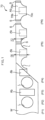
- the difference in velocity of the anvil is obtained by asymmetrically forming the cam groove 3a of FIG. 3 so that the cam (follower) 23 of FIG. 3 is at the position of one end in the axial direction of the cam drum when at the rotational position R0 (the origin position) of FIG. 8 and is at the position of the other end in the axial direction of the cam drum when at the rotational position R3 (the stroke end) of FIG. 8 .
- control unit 500 controls the ultrasonic wave generator 16 so as to perform welding only in the outward path in this example
- control unit 500 may have different modes of control so as to perform welding only in the return path or both in the outward path and in the return path.
- the web W is conveyed in the circumferential direction by the conveying drum 200 .
- the anvil 15 reciprocates in the axis L1 direction of the conveying drum 200 as shown in FIG. 9 and FIG. 10 .
- the web W is held between the anvil 15 and the horn 14 .
- Ultrasonic energy is applied to the web W sandwiched between the anvil 15 and the horn 14 by vibrating the horn 14 of FIG. 9 .
- the horn 14 vibrates, for example, in a direction that intersects with the surface Ws of the web W .
- the anvil 15 moves at the first velocity V1 over the welding area ⁇ , which corresponds to the second section of the outward path OB , in which the anvil 15 of FIG. 9 moves straight from the origin position to the stroke end.
- the control unit 500 ( FIG. 3 ) vibrates the horn 14 via the ultrasonic wave generator 16 to apply ultrasonic energy to the web W held between the anvil 15 and the horn 14 to form the welded portion S on the web W as shown in gray in FIG. 10 .
- the anvil 15 is moved to overrun beyond the welding area ⁇ of the web W , and a control may be performed so as not to vibrate the horn 14 in the overrun area ⁇ .
- the settings may be such that the horn 14 vibrates not only in the welding area ⁇ , but also immediately before entering and immediately after exiting the welding area ⁇ , in preparation for cases where the web W is displaced in a direction that intersects with the conveyance direction (the axis L1 direction).
- control unit 500 controls the ultrasonic wave generator 16 so as not to apply ultrasonic energy to the web W .
- the horn 14 may be controlled not to vibrate when not applying ultrasonic energy to the web W .
- the average moving velocity of the anvil 15 in the outward path OB is less than the average moving velocity of the anvil 15 in the return path IB .
- the moving velocity of the anvil 15 passing through the welding area ⁇ in the outward path OB is less than the moving velocity of the anvil 15 passing through the welding area ⁇ in the return path IB .
- the amplitude of the ultrasonic wave, the pressing force of the horn 14 and the anvil 15 against the web W , the moving velocity of the anvil 15 , the welding area per unit area and the number of welding surfaces may be changed as needed.
- the anvil may be arranged on the inner side in the radial direction of the outer circumferential surface of the web support member, and the horn may be arranged on the outer side of the outer circumferential surface.
- Only one set of a horn and an anvil may be provided, or multiple sets may be provided, on the drum.
- Portions of a pants-type worn article other than the so-called side seals may be welded.
- the present invention can be used in production equipment for disposable worn articles such as disposable pants, diapers, sanitary products, etc., as well as in production equipment for wound dressing materials for medical use, etc.
Landscapes
- Engineering & Computer Science (AREA)
- Mechanical Engineering (AREA)
- Health & Medical Sciences (AREA)
- Heart & Thoracic Surgery (AREA)
- Epidemiology (AREA)
- Biomedical Technology (AREA)
- Vascular Medicine (AREA)
- Life Sciences & Earth Sciences (AREA)
- Animal Behavior & Ethology (AREA)
- General Health & Medical Sciences (AREA)
- Public Health (AREA)
- Veterinary Medicine (AREA)
- Manufacturing & Machinery (AREA)
- Lining Or Joining Of Plastics Or The Like (AREA)
- Absorbent Articles And Supports Therefor (AREA)
Abstract
Description
- The present invention relates to a device and a method for ultrasonic welding.
- A device having a horn that rotates together with a drum and an anvil that cooperates with the horn has been known in the art, in which the anvil reciprocates in the axial direction of the drum as the drum rotates so as to perform a welding process on a web held between the horn and the anvil (the first patent document).
- [FIRST PATENT DOCUMENT]
Japanese Patent No. 6228232 - With this prior art, the welding process is performed in both of the reciprocating movements of the anvil, but there have been problems such as unstable welding strength and deteriorated appearance due to misalignment between the weld trace of the outward path and the weld trace of the return path caused by the web being misaligned while the anvil reciprocates.
- Therefore, an object of the present invention is to provide a device and a method for ultrasonic welding capable of realizing stable weld strength and forming a weld trace of excellent appearance.
- An ultrasonic welding device of the present invention includes:
- a conveying
drum 200 that conveys a web W along an outercircumferential surface 44a of thedrum 200 while rotating; - at least one
horn 14 that is arranged on one of an inner side and an outer side in a radial direction of the conveyingdrum 200 relative to the outercircumferential surface 44a, and that rotates together with the conveyingdrum 200; - at least one
anvil 15 that is arranged on the other one of the inner side and the outer side in the radial direction of the conveyingdrum 200 relative to the outercircumferential surface 44a, and that rotates together with theconveying drum 200; - a
moving mechanism 300 that reciprocates theanvil 15 in an axis L1 direction of theconveying drum 200 as the conveyingdrum 200 rotates so as to hold the web W between theanvil 15 and thehorn 14 in an outward path OB and a return path IB of theanvil 15; - an
ultrasonic wave generator 16 that vibrates thehorn 14 to apply ultrasonic energy to the web W sandwiched between theanvil 15 and thehorn 14; and - a
control unit 500 that performs a control of vibrating thehorn 14 via theultrasonic wave generator 16 so as to apply ultrasonic energy to the web W in one of the outward path OB and the return path IB and (whereas) not to apply ultrasonic energy to the web W in the other one of the outward path OB and the return path IB. - On the other hand, an ultrasonic welding method of the present invention is an ultrasonic welding method of welding a web W by means of an ultrasonic welding device, the ultrasonic welding device including:
- a conveying
drum 200 that conveys the web W along an outercircumferential surface 44a of thedrum 200 while rotating; - at least one
horn 14 that is arranged on one of an inner side and an outer side in a radial direction of the conveyingdrum 200 relative to the outercircumferential surface 44a, and that rotates together with the conveyingdrum 200; and - at least one
anvil 15 that is arranged on the other one of the inner side and the outer side in the radial direction of the conveyingdrum 200 relative to the outercircumferential surface 44a, and that rotates together with the conveyingdrum 200; the ultrasonic welding method including:- a step of conveying the web W by the conveying
drum 200; - a step of reciprocating the
anvil 15 in an axis L1 direction of the conveyingdrum 200 as theconveying drum 200 rotates so as to hold the web W between theanvil 15 and thehorn 14 in an outward path OB and a return path IB of theanvil 15; - a step of vibrating the
horn 14 to apply ultrasonic energy to the web W sandwiched between theanvil 15 and thehorn 14; and - a step of controlling vibration of the
horn 14 via anultrasonic wave generator 16 so as to apply ultrasonic energy to the web W in one of the outward path OB and the return path IB and (whereas) not to apply ultrasonic energy to the web W in another one of the outward path OB and the return path IB.
- a step of conveying the web W by the conveying
- According to the present invention, the web is welded only in one of the outward path and the return path. Therefore, there will not be misalignment between weld traces, the welding strength will not be unstable, and the appearance will not deteriorate.
- As used in the present invention, "to weld a web" may be to weld together a plurality of webs that are laid on each other or may be to weld a single layered web folded in two, i.e., so-called side sealing.
-
-
FIG. 1 is a process diagram illustrating the outline of a method for manufacturing a disposable diaper according to the present invention. -
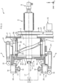
FIG. 2 is a front view of a main part of an ultrasonic welding device according to the present invention. -
FIG. 3 is a cross-sectional view taken along line III-III ofFIG. 2 . -
FIG. 4 is a cross-sectional view showing a part ofFIG. 3 on an enlarged scale. -
FIG. 5 is a front view showing a horn holding mechanism ofFIG. 4 . -
FIG. 6 is a cross-sectional view taken along line VI-VI ofFIG. 4 . -
FIG. 7 is cross-sectional view taken along line VII-VIIFIG. 4 . -
FIG. 8 is a schematic diagram showing the relationship between a rotational position and a linear position of an anvil. -
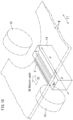
FIG. 9 is a schematic perspective view showing a linear motion of the anvil in the outward path. -
FIG. 10 is a schematic perspective view showing a linear motion of the anvil in the return path. - Preferably, in the present invention, the
control unit 500 controls theultrasonic wave generator 16 so as not to vibrate thehorn 14 when ultrasonic energy is not applied to the web W. - In this case, it is possible to suppress generation of unnecessary vibration to the web W being conveyed.
- Preferably, in the present invention, the
moving mechanism 300 is configured so that theanvil 15 reciprocates so that an average moving velocity of theanvil 15 in the one of the outward path OB and the return path IB in which ultrasonic energy is applied is smaller than that in the other one of the outward path OB and the return path IB. - In this case, it is possible to sufficiently weld the web because the moving velocity of the anvil in the one path is small, while the amount of time taken for reciprocation of the anvil required for a welding process will not be large because the moving velocity of the anvil in the other path is large.
- Preferably, in the present invention, the
moving mechanism 300 is configured so that theanvil 15 overruns beyond a welding area α where the web W should be welded. - In this case, ultrasonic welding can be performed on the web over the entire range in a direction that intersects with the conveyance direction of the web.
- Preferably, in the present invention, the
control unit 500 controls theultrasonic wave generator 16 so as not to vibrate thehorn 14 in the overrun area β. - In this case, it is possible to prevent damage due to contact between the anvil and the horn.
- Any feature illustrated and/or depicted in conjunction with one of the aforementioned aspects or the following embodiments may be used in the same or similar form in one or more of the other aspects or other embodiments, and/or may be used in combination with, or in place of, any feature of the other aspects or embodiments.
- The present invention will be understood more clearly from the following description of preferred embodiments taken in conjunction with the accompanying drawings. Note however that the embodiments and the drawings are merely illustrative and should not be taken to define the scope of the present invention. The scope of the present invention shall be defined only by the appended claims. In the accompanying drawings, like reference numerals denote like components throughout the plurality of figures.
- Before describing a device according to the present invention, the structure of a
disposable diaper 70, which is an example product manufactured by the device, and the manufacturing method thereof will be described. - Referring to
FIG. 1 , thedisposable diaper 70 includes afront abdomen portion 70a which, when worn, is arranged on the abdomen of the wearer, arear back portion 70b which is positioned on the buttocks of the wearer, and acrotch portion 70c which extends from thefront abdomen portion 70a through between both legs of the wearer to therear back portion 70b. - The opposite side edge portions of the
front abdomen portion 70a and the opposite side edge portions of therear back portion 70b are welded to each other by two welded portions S so that thefront abdomen portion 70a and therear back portion 70b are linked together into a ring form. - The outline of the method for manufacturing the
disposable diaper 70 will now be described. - In the conveying step P1, a web W extending in a particular direction is conveyed along its longitudinal direction. The flow direction of the web W will be hereinafter described as the horizontal direction, and the direction orthogonal to the horizontal direction in
FIG. 1 as the vertical direction. - The web W includes an inner web that faces toward the body surface of the wearer when worn, an outer web that faces away from the wearer when worn, and elastic members sandwiched between the inner web and the outer web. Note that the inner web, the outer web and the elastic members are not shown in the figures.
- In the leg hole formation step P2, leg holes L are formed at the center position in the vertical direction of the web W.
- The area between two leg holes L in the web W is a portion that corresponds to the
crotch portion 70c. The opposite positions in the vertical direction relative to the portion that corresponds to acrotch portion 70c in the web W are portions that correspond respectively to the frontabdomen portion 70a and therear back portion 70b. - In the absorbent body attachment step P3, an absorbent body Ab is attached to a position between two leg holes L on the web W.
- The absorbent body Ab includes a permeable sheet having liquid permeability, a water-repellent sheet having water repellency and air permeability, and an absorbent core sandwiched between the permeable sheet and the water-repellent sheet. Note that the permeable sheet, the water-repellent sheet and the absorbent core are not shown in the figures.
- Note that although the method for attaching the absorbent body Ab on the web W is described, the attachment may be done with the absorbent core sandwiched between the inner web and the outer web of the web W. In this case, the inner web is formed of a liquid-permeable sheet, and the outer web is formed of a water-repellent and air-permeable sheet.
- In the two-fold step P4, the web W on which the absorbent body Ab is placed is folded in two in the vertical direction. Thus, a portion of the web W that corresponds to the front
abdomen portion 70a and a portion thereof that corresponds to therear back portion 70b are laid on each other. - In the welding step P5, a portion of the two-folded web W (the object to be welded) that corresponds to the side edge portion of the front
abdomen portion 70a and a portion thereof that corresponds to the side edge portion of therear back portion 70b are ultrasonically welded to each other between two absorbent bodies Ab adjacent to each other. - Specifically, in the welding step P5, the web W is ultrasonically welded over a range that includes the position at which the web W is severed in the cut-off step P6 to be described below. Thus, side sealing is done, making the torso portion of the worn article into a loop, thereby turning the diaper into a pants-type diaper.
- Note that the welded portions S are formed over a welding range D1 in the vertical direction respectively for a portion that corresponds to the side edge portion of the front
abdomen portion 70a and for a portion that corresponds to the side edge portion of therear back portion 70b. - In the cut-off step P6, the web W is cut off along the cut-off line extending in the vertical direction at the center position of the welded portion S formed in the welding step P5. Thus, the web W (continuous material) is cut off into
disposable diapers 70. - Next, the outline of the
ultrasonic welding device 1 according to the present invention will be described. - As shown in
FIG. 2 , theultrasonic welding device 1 includes a conveyingdrum 200 which rotates and conveys the web W along the outercircumferential surface 44a in the circumferential direction. - Note that the circumferential velocity of the conveying
drum 200 and the conveying velocity of the web W are set to be equal to each other so that the web W does not slip on the outercircumferential surface 44a. - The conveying
drum 200 includes ahorn 14, which is arranged on the inner side in the radial direction of the conveyingdrum 200 relative to the outercircumferential surface 44a, and rotates together with the conveyingdrum 200. - The conveying
drum 200 includes ananvil 15, which is arranged on the outer side in the radial direction of the conveyingdrum 200 relative to the outercircumferential surface 44a, and rotates together with the conveyingdrum 200. - In this example, ten
horns 14 and tenanvils 15 are provided. - The moving
mechanism 300 ofFIG. 4 reciprocates theanvil 15 in the axis L1 direction of the conveyingdrum 200 as the conveyingdrum 200 rotates. - As will be described below, the web W (
FIG. 2 ) is held between theanvil 15 and thehorn 14 in the outward path and the return path of theanvil 15. - Note that the web W is not shown in
FIG. 3 to FIG. 7 . - An
ultrasonic wave generator 16 ofFIG. 2 is provided for eachhorn 14 and vibrates thehorn 14 to apply ultrasonic energy to the web W sandwiched between theanvil 15 and thehorn 14. Thehorn 14 vibrates, for example, in a direction that intersects with the surface of the web W. - The
control unit 500 ofFIG. 3 performs a control of vibrating thehorn 14 via theultrasonic wave generator 16 so as to apply ultrasonic energy to the web W in either one of the outward path and the return path and not to apply ultrasonic energy to the web W in the other one of the outward path OB and the return path IB. - The
control unit 500 in this example controls theultrasonic wave generator 16 so as to apply ultrasonic energy to the web W in the outward path OB and not to apply ultrasonic energy to the web W in the return path IB. - Note that "not apply ultrasonic energy" as used in the present specification includes the case where the horn is vibrating to such an extent that the web is not welded.
- Next, referring to
FIG. 2 , theultrasonic welding device 1 performing the welding step P5 will be described in detail. - The
ultrasonic welding device 1 is for ultrasonically welding the web W, which has been folded in two in the two-fold step P4 and introduced via an inlet roller F1, and to send the welded web W to the cut-off step P6 via an outlet roller F2. - Specifically, as shown in
FIG. 3 , theultrasonic welding device 1 includes: a driveshaft support member 2 provided upright on a predetermined work surface; a cam drum (drive mechanism) 3 fixed to the driveshaft support member 2; a cam follower (drive mechanism) 23 provided in acam groove 3a of thecam drum 3; a drive shaft 4 supported so that the drive shaft 4 can rotate relative to the driveshaft support member 2 about the axis L1; arotating drum 5 fixed to the drive shaft 4; tenwelding units 6 fixed to therotating drum 5; ten power transmission mechanisms 7 (only two are shown inFIG. 3 ) for transmitting power from thecam drum 3 and thecam follower 23 to thewelding unit 6; a slip ring (rotary connector) 8 and a rotary joint 9 provided at the proximal portion of the drive shaft 4; awire guide member 11 and apipe connection member 12 provided at the distal portion of the drive shaft 4; and amotor 10 for rotationally driving the drive shaft 4. - Note that in
FIG. 3 , the X direction is the direction parallel to the axis L1 of the drive shaft 4, the Z direction is the up-down direction ofFIG. 3 , the Y direction is the direction orthogonal to the X-Z plane. - Referring to
FIG. 3 andFIG. 4 , the driveshaft support member 2 supports the elements described above (excluding the drive shaft support member 2) of theultrasonic welding device 1 on the work surface. Specifically, the driveshaft support member 2 is a plate-shaped member with a throughhole 2a passing through the driveshaft support member 2 in the X direction. - The
cam drum 3 is fixed to the driveshaft support member 2 with one end thereof in the X direction fitted into the throughhole 2a of the driveshaft support member 2. In this state, the axis of thecam drum 3 is aligned with the axis L1. - The
cam groove 3a is formed on the outer circumferential surface of thecam drum 3. Thecam groove 3a has a shape that permits thecam follower 23, which rotates about the axis L1, to move in the X direction, as will be described in detail below. Note that thecam drum 3 and thecam follower 23 correspond to the drive mechanism for driving theanvil 15 to be described below so that theanvil 15 moves relative to thehorn 14. - As shown in
FIG. 3 , the drive shaft 4 is rotationally driven by themotor 10. Specifically, a belt V1 is wound around a pulley 4a provided at a middle portion of the drive shaft 4 and apulley 10a provided on the output shaft of themotor 10. The power of themotor 10 is transmitted to the drive shaft 4 via the belt V1 as the output shaft of themotor 10 rotates. Note that themotor 10 is fixed to the driveshaft support member 2 via a bracket (not shown). - The drive shaft 4 passes through the
cam drum 3 in the X direction in such a state that the drive shaft 4 can rotate relative to thecam drum 3. That is, the drive shaft 4 is supported indirectly by the driveshaft support member 2 via thecam drum 3. The proximal portion of the drive shaft 4 is located on the opposite side of the driveshaft support member 2 from thecam drum 3, and the distal portion of the drive shaft 4 is located on the opposite side of thecam drum 3 from the driveshaft support member 2. - The
rotating drum 5 includes adisc 5a fixed to the distal portion of the drive shaft 4, a coveringwall 5b extending in the X direction from the peripheral portion of thedisc 5a and covering the outer circumferential surface of thecam drum 3, and anadjustment plate 5c removably attached to the opposite side of thedisc 5a from the coveringwall 5b. Note that thedisc 5a and theadjustment plate 5c correspond to a rotor capable of rotating about the axis L1. - The
adjustment plate 5c hasscrew holes 5e (seeFIG. 4 ) for attaching thewelding unit 6. - The
welding unit 6 including thehorn 14 and theanvil 15 will now be described with reference toFIG. 4 to FIG. 7 . Note that since tenwelding units 6 have an identical configuration, only the configuration of onewelding unit 6 shown inFIG. 4 to FIG. 7 will be described. - The
welding unit 6 includes: the horn (second welder) 14 and the anvil (first welder) 15 for welding the web W by sandwiching the web W therebetween; theultrasonic wave generator 16 connected to thehorn 14; a cooling jacket 17 (cooler) for cooling theultrasonic wave generator 16; anattachment portion 18 that permits thewelding unit 6 to be attached to the rotating drum 5 (theadjustment plate 5c); a base 19 linked to an end portion of theattachment portion 18 and extending in the X direction; ahorn holding mechanism 20 provided at the distal portion of thebase 19 for holding thehorn 14; and ananvil holding mechanism 21 provided at the proximal portion of thebase 19 for holding theanvil 15. - The
attachment portion 18 permits thewelding unit 6 to be attached to therotating drum 5 with thehorn holding mechanisms 20 being arranged on an identical circumference about the axis L1 as shown inFIG. 2 andFIG. 3 . Moreover, theattachment portion 18 can be attached to the rotating drum 5 (theadjustment plate 5c) so that the attachment position of the weldedunit 6 to therotating drum 5 can be adjusted in the radial direction about the axis L1 (in the Z direction inFIG. 4 to FIG. 6 ). - Referring to
FIG. 4 andFIG. 5 , thehorn holding mechanism 20 holds thehorn 14 in an open position with thehorn 14 facing outward in the radial direction. - Specifically, the
horn holding mechanism 20 includes a coveringmember 42 that covers thehorn 14 from one side in the radial direction (the lower side inFIG. 4 andFIG. 5 ) and from both sides in the Y direction, ahorn support member 43 that supports thehorn 14 inside the coveringmember 42, and a pair of web support members (welded portion support members) 44 fixed to the coveringmember 42. - The covering
member 42 includes a bottom plate 42a and a pair ofside plates 42b provided upright on opposite end portions of the bottom plate 42a in the Y direction. Aninsertion hole 42c extending in the Z direction is formed in the bottom plate 42a. Theultrasonic wave generator 16 arranged on the inner side in the radial direction of the coveredmember 42 is connected to thehorn 14 through theinsertion hole 42c. - The
horn support member 43 is fixed to the coveringmember 42 and supports a middle portion of the horn 14 (a portion thereof that corresponds to a node of vibration from the ultrasonic wave generator 16). Note that the width dimension of thehorn 14 in the X direction corresponds to the width of the welding range D1 of the welded portion S formed on the web W (seeFIG. 1 ). - The
web support members 44 are attached to the end faces of theside plates 42b so as to extend in the circumferential direction about the axis L1 on both sides of the tip of thehorn 14. Specifically, eachweb support member 44 includes asupport portion 44a (the outercircumferential surface 44a) extending from thehorn 14 in the circumferential direction, and abent portion 44b that is bent from the end portion in the circumferential direction. Note that thedisc 5a, theadjustment plate 5c, theattachment portion 18 and theweb support member 44 of therotating drum 5 correspond to a rotating support mechanism that is capable of rotating about the axis L1 and capable of supporting the continuously supplied web W on the circumference about the axis L1. - The outer
circumferential surface 44a in the radial direction of theweb support member 44 serves as a support surface for supporting the web W. Specifically, the width dimension in the x-direction of the outercircumferential surface 44a corresponds to the width dimension D2 (seeFIG. 1 ) between the end portion of the web W on the waist side and the end portion of the web W on the crotch side. - As shown in
FIG. 5 , thebent portion 44b is bent from thesupport portion 44a so that thebent portion 44b is located on the side of the axis L1 (FIG. 4 ) relative to the straight line L2 that connects together the distal portions of thesupport portions 44a adjacent to each other between twohorns 14. - Thus, a portion of the web W (see
FIG. 1 ) that includes the welded portion S can be supported by thesupport portion 44a and the tip of thehorn 14, and a portion of the web W that includes the absorbent body Ab thicker than the welded portion S can be arranged betweenbent portions 44b adjacent to each other. Therefore, as opposed to cases where the web W is supported on the same surface, it is possible to suppress the lifting of portions of the web W other than the absorbent body Ab due to the thickness of the absorbent body Ab. - Referring to
FIG. 4 to FIG. 7 , theanvil holding mechanism 21 holds theanvil 15 so that theanvil 15 can move in the X direction relative to the horn holding mechanism 20 (the horn 14). - Specifically, as shown in
FIG. 6 andFIG. 7 , theanvil holding mechanism 21 includes: a pair ofrail holding plates 45 provided upright on thebase 19 and facing each other in the Y direction; a pair ofrails 46 that are held respectively by therail holding plates 45; a pair ofsliders 47 that engage respectively with therails 46 so that asliders 47 can move in the X direction; abody portion 48 to which asliders 47 are fixed; threerotating shafts 49 to 51 provided on thebody portion 48; four timingpulleys 52 to 55 that can rotate about the rotatingshafts 49 to 51; timing belts V2, V3 wound around the timing pulleys 52 to 55; and a link member (seeFIG. 4 ) 59 that links together the timing belt V2 and therail holding plate 45. - The
body portion 48 is attached to the rail holding plate 45 (the base 19) so that thebody portion 48 can move in the X direction by the engagement between therails 46 and thesliders 47. - As shown in
FIG. 7 , the rotatingshafts 49 to 51 extend in the Y direction to be next to each other in the X direction, and are capable of rotating relative to thebody portion 48 about axes extending in the Y direction. The timingpulley 52 is provided at one end of therotating shaft 49. The timingpulley 53 is provided at the end of therotating shaft 50 on the same side as the timingpulley 52, and the timingpulley 54 is provided at the end of therotating shaft 50 on the opposite side to the timingpulley 53. The timingpulley 55 is provided at the end of therotating shaft 51 on the same side as the timingpulley 54, and theanvil 15 is provided at the end of therotating shaft 51 on the opposite side to the timingpulley 55. - The timing belt V2 is wound around the timing
pulley 52 and the timingpulley 53. The timing belt V3 is wound around the timingpulley 54 and the timingpulley 55. Thelink member 59 links together therail holding plate 45 and a part of the timing belt V2 that is located on the axis L1 side with respect to the timing pulleys 52, 53. - When the
body portion 48 moves in the X direction relative to the rail holding plate 45 (the base 19), a force is transmitted from therail holding plate 45 through thelink member 59 to move the timing belt V2 in the X direction. This causes the timing pulleys 52, 53 to rotate, and the timingpulley 54 rotates as the timingpulley 53 rotates. As a result, the movement of the timing belt V3 causes timingpulley 55 to rotate, which in turn causes theanvil 15 to rotate. - Details of the structure of the ultrasonic welding device as described above are disclosed in
US 2017/0027762 A1 , the entire disclosure of which is hereby incorporated by reference. - Here, the relationship between the rotational position of the
anvil 15 about the axis L1 inFIG. 3 and the linear position is set by thecam groove 3a as follows, for example. - In the range (the first section) from the rotational position R0 to the rotational position R1 of
FIG. 8 , theanvil 15 accelerates from the origin position (FIG. 9 ) of the linear motion toward the stroke end (FIG. 10 ) (hereinafter this direction is called forward). - In the range (the second section) from the rotational position R1 to the rotational position R2, the
anvil 15 moves at a constant velocity (the first velocity V1) in the forward direction. During this movement, the web W is welded between thehorn 14 and theanvil 15. - In the range (the third section) from the rotational position R2 to the rotational position R3, the
anvil 15 decelerates (giving backward acceleration to the anvil 15) to stop at the stroke end (FIG. 10 ) at the rotational position R3. - In this example, the web W is not welded during the movement in which the
anvil 15 returns from the rotational position R2 to the original rotational position R0. - In the range (the fourth section) from the rotational position R3 to the rotational position R4, the
anvil 15 accelerates backward from the stroke end toward the origin position. - In the range (the fifth section) from the rotational position R4 to the rotational position R5, the
anvil 15 moves backward at a constant velocity (the second velocity V2). - In the range (the sixth section) from the rotational position R5 to the rotational position R0, the
anvil 15 decelerates (giving forward acceleration to the anvil 15) so that theanvil 15 stops at the origin position at the rotational position R0. - The circumferential rotation of the conveying
drum 200 ofFIG. 2 is at a constant velocity, and thus thewelding unit 6 including the anvils and the horns also rotates at a constant circumferential velocity together with the conveyingdrum 200. - On the other hand, as shown in
FIG. 8 , the first to third sections T1 to T3, which correspond to the outward path OB, are longer in distance than the fourth to sixth sections T4 to T6, which correspond to the return path IB. - In this example, the first velocity V1 of the
anvil 15 in the second section T2 where welding is performed is smaller than the second velocity V2 of theanvil 15 in the fifth section T5 where welding is not performed. Therefore, the welding strength is stable even if welding is performed only in the outward path. - On the other hand, in this example, the second velocity V2 is greater than the first velocity V1, and the average moving velocity of the
anvil 15 in the return path IB is greater than the average moving velocity of theanvil 15 in the outward path OB. Therefore, the amount of time taken for theanvil 15 to move from the origin position to the stroke end and back again to the origin position is not long. - Note that in this example, the moving
mechanism 300 is configured so that the average moving velocity of theanvil 15 in the outward path OB, where the ultrasonic energy is applied, is less than that in the return path. - Thus, the difference in velocity of the anvil is obtained by asymmetrically forming the
cam groove 3a ofFIG. 3 so that the cam (follower) 23 ofFIG. 3 is at the position of one end in the axial direction of the cam drum when at the rotational position R0 (the origin position) ofFIG. 8 and is at the position of the other end in the axial direction of the cam drum when at the rotational position R3 (the stroke end) ofFIG. 8 . - Note that while the
control unit 500 controls theultrasonic wave generator 16 so as to perform welding only in the outward path in this example, thecontrol unit 500 may have different modes of control so as to perform welding only in the return path or both in the outward path and in the return path. - Next, the outline of an example of the ultrasonic welding method of the present invention will be described.
- As shown in
FIG. 2 , the web W is conveyed in the circumferential direction by the conveyingdrum 200. - As the conveying
drum 200 rotates, theanvil 15 reciprocates in the axis L1 direction of the conveyingdrum 200 as shown inFIG. 9 andFIG. 10 . - During the reciprocation of the
anvil 15 through the outward path OB (FIG. 9 ) and the return path IB (FIG. 10 ), the web W is held between theanvil 15 and thehorn 14. - Ultrasonic energy is applied to the web W sandwiched between the
anvil 15 and thehorn 14 by vibrating thehorn 14 ofFIG. 9 . Thehorn 14 vibrates, for example, in a direction that intersects with the surface Ws of the web W. - In this example, the
anvil 15 moves at the first velocity V1 over the welding area α, which corresponds to the second section of the outward path OB, in which theanvil 15 ofFIG. 9 moves straight from the origin position to the stroke end. - In the welding area α, the control unit 500 (
FIG. 3 ) vibrates thehorn 14 via theultrasonic wave generator 16 to apply ultrasonic energy to the web W held between theanvil 15 and thehorn 14 to form the welded portion S on the web W as shown in gray inFIG. 10 . - In this example, the
anvil 15 is moved to overrun beyond the welding area α of the web W, and a control may be performed so as not to vibrate thehorn 14 in the overrun area β. - On the other hand, the settings may be such that the
horn 14 vibrates not only in the welding area α, but also immediately before entering and immediately after exiting the welding area α, in preparation for cases where the web W is displaced in a direction that intersects with the conveyance direction (the axis L1 direction). - In the return path IB in which the
anvil 15 ofFIG. 10 returns from the stroke end to the origin position, thecontrol unit 500 controls theultrasonic wave generator 16 so as not to apply ultrasonic energy to the web W. - The
horn 14 may be controlled not to vibrate when not applying ultrasonic energy to the web W. - In this example, the average moving velocity of the
anvil 15 in the outward path OB is less than the average moving velocity of theanvil 15 in the return path IB. In particular, the moving velocity of theanvil 15 passing through the welding area α in the outward path OB is less than the moving velocity of theanvil 15 passing through the welding area α in the return path IB. - In the welding area α, the amplitude of the ultrasonic wave, the pressing force of the
horn 14 and theanvil 15 against the web W, the moving velocity of theanvil 15, the welding area per unit area and the number of welding surfaces may be changed as needed. - While preferred embodiments have been described above with reference to the drawings, obvious variations and modifications will readily occur to those skilled in the art upon reading the present specification.
- For example, the anvil may be arranged on the inner side in the radial direction of the outer circumferential surface of the web support member, and the horn may be arranged on the outer side of the outer circumferential surface.
- Only one set of a horn and an anvil may be provided, or multiple sets may be provided, on the drum.
- Portions of a pants-type worn article other than the so-called side seals may be welded.
- Thus, such variations and modifications shall fall within the scope of the present invention as defined by the appended claims.
- The present invention can be used in production equipment for disposable worn articles such as disposable pants, diapers, sanitary products, etc., as well as in production equipment for wound dressing materials for medical use, etc.
-
- 1: Ultrasonic welding device, 2: Drive shaft support member, 2a: Through hole, 3: Cam drum, 3a: Cam groove, 4: Drive shaft, 4a: Pulley, 5: Rotating drum, 5a: Disc, 5b: Covering wall, 5c: Adjustment plate, 5e: Screw hole, 6: Welding unit, 7: Power transmission mechanism, 8: Slip ring, 9: Rotary joint
- 10: Motor, 10a: Pulley, 11: Wire guide member, 12: Pipe connection member, 14: Horn, 15: Anvil, 16: Ultrasonic wave generator, 17: Cooling jacket, 18: Attachment portion, 19: Base
- 20: Horn holding mechanism, 21: Anvil holding mechanism, 23: Cam follower
- 42: Covering member, 42a: Bottom plate, 42b: Side plate, 42c: Through hole, 43: Horn holding member, 44: Web support member, 44a: Outer circumferential surface, 44b: Bent portion, 45: Rail holding plate, 46: Rail, 47: Slider, 48: Body portion, 49 to 51: Rotating shaft
- 52 to 55: Timing pulley, 59: Link member
- 70: Disposable diaper, 70a: Front abdomen portion, 70b: Rear back portion, 70c: Crotch portion
- 200: Conveying drum
- 300: Moving mechanism
- 500: Control unit
- Ab: Absorbent body, D1: Welding range, D2: Width dimension, F1: Inlet roller, F2: Outlet roller, L: Leg hole, L 1: Axis, L2: Straight line, S: Welded portion
- OB: Outward path, IB: Return path
- P1: Conveying step, P2: Leg hole formation step, P3: Absorbent body attachment step, P4: Two-fold step, P5: Welding step, P6: Cut-off step
- V1: Belt, V2, V3: Timing belt, W: Web, Ws: Surface of web
- α: Welding area, β: Overrun area
Claims (10)
- An ultrasonic welding device, comprising:a conveying drum 200 that conveys a web W along an outer circumferential surface 44a while rotating;at least one horn 14 that is arranged on one of an inner side and an outer side in a radial direction of the conveying drum 200 relative to the outer circumferential surface 44a, the horn 14 rotating together with the conveying drum 200;at least one anvil 15 that is arranged on another one of the inner side and the outer side in the radial direction of the conveying drum 200 relative to the outer circumferential surface 44a, the anvil 15 rotating together with the conveying drum 200;a moving mechanism 300 that reciprocates the anvil 15 in an axis L1 direction of the conveying drum 200 as the conveying drum 200 rotates so as to hold the web W between the anvil 15 and the horn 14 in an outward path OB and a return path IB of the anvil 15;an ultrasonic wave generator 16 that vibrates the horn 14 to apply ultrasonic energy to the web W sandwiched between the anvil 15 and the horn 14; anda control unit 500 that performs a control of vibrating the horn 14 via the ultrasonic wave generator 16 so as to apply ultrasonic energy to the web W in one of the outward path OB and the return path IB and not to apply ultrasonic energy to the web W in another one of the outward path OB and the return path IB.
- The ultrasonic welding device according to claim 1, wherein the control unit 500 controls the ultrasonic wave generator 16 so as not to vibrate the horn 14 when ultrasonic energy is not applied to the web W.
- The ultrasonic welding device according to claim 1 or 2, wherein the moving mechanism 300 is configured so that an average moving velocity of the anvil 15 in the one of the outward path OB and the return path IB in which ultrasonic energy is applied is smaller than an average moving velocity of the anvil 15 in the other one of the outward path OB and the return path IB.
- The ultrasonic welding device according to any one of claims 1 to 3, wherein the moving mechanism 300 is configured so that the anvil 15 overruns beyond a welding area α where the web W should be welded.
- The ultrasonic welding device according to claim 4, wherein the control unit 500 performs a control so that the ultrasonic wave generator 16 does not vibrate the horn 14 in the overrun area β.
- An ultrasonic welding method of welding a web W by means of an ultrasonic welding device, the ultrasonic welding device comprising:a conveying drum 200 that conveys the web W along an outer circumferential surface 44a while rotating;at least one horn 14 that is arranged on one of an inner side and an outer side in a radial direction of the conveying drum 200 relative to the outer circumferential surface 44a, the horn 14 rotating together with the conveying drum 200; andat least one anvil 15 that is arranged on another one of the inner side and the outer side in the radial direction of the conveying drum 200 relative to the outer circumferential surface 44a, the anvil 15 rotating together with the conveying drum 200; the ultrasonic welding method comprising:a step of conveying the web W by the conveying drum 200;a step of reciprocating the anvil 15 in an axis L1 direction of the conveying drum 200 as the conveying drum 200 rotates so as to hold the web W between the anvil 15 and the horn 14 in an outward path OB and a return path IB of the anvil 15;a step of vibrating the horn 14 to apply ultrasonic energy to the web W sandwiched between the anvil 15 and the horn 14; anda step of controlling vibration of the horn 14 via an ultrasonic wave generator 16 so as to apply ultrasonic energy to the web W in one of the outward path OB and the return path IB and not to apply ultrasonic energy to the web W in another one of the outward path OB and the return path IB.
- The ultrasonic welding method according to claim 6, wherein a control is performed so as not to vibrate the horn 14 when ultrasonic energy is not applied to the web W.
- The ultrasonic welding method according to claim 6 or 7, wherein the anvil 15 reciprocates so that an average moving velocity of the anvil 15 in the one of the outward path OB and the return path IB in which ultrasonic energy is applied is smaller than an average moving velocity of the anvil 15 in the other one of the outward path OB and the return path IB.
- The ultrasonic welding method according to any one of claims 6 to 8, wherein the anvil 15 moves so as to overrun beyond a welding area α where the web W should be welded.
- The ultrasonic welding method according to claim 9, wherein the horn 14 is not vibrated in the overrun area β.
Applications Claiming Priority (2)
| Application Number | Priority Date | Filing Date | Title |
|---|---|---|---|
| JP2020189438 | 2020-11-13 | ||
| PCT/JP2021/037664 WO2022102317A1 (en) | 2020-11-13 | 2021-10-12 | Apparatus and method for ultrasonic welding |
Publications (2)
| Publication Number | Publication Date |
|---|---|
| EP4245275A1 true EP4245275A1 (en) | 2023-09-20 |
| EP4245275A4 EP4245275A4 (en) | 2024-04-24 |
Family
ID=81600974
Family Applications (1)
| Application Number | Title | Priority Date | Filing Date |
|---|---|---|---|
| EP21891564.3A Pending EP4245275A4 (en) | 2020-11-13 | 2021-10-12 | DEVICE AND METHOD FOR ULTRASONIC WELDING |
Country Status (5)
| Country | Link |
|---|---|
| US (1) | US12409610B2 (en) |
| EP (1) | EP4245275A4 (en) |
| JP (1) | JP7794756B2 (en) |
| CN (1) | CN116507303A (en) |
| WO (1) | WO2022102317A1 (en) |
Family Cites Families (11)
| Publication number | Priority date | Publication date | Assignee | Title |
|---|---|---|---|---|
| US5660679A (en) | 1995-01-31 | 1997-08-26 | Kimberly-Clark Worldwide, Inc. | Rotary sealing system |
| JP5591051B2 (en) | 2010-09-30 | 2014-09-17 | ユニ・チャーム株式会社 | Apparatus and method for sonicating a web |
| WO2014200102A1 (en) * | 2013-06-14 | 2014-12-18 | 株式会社瑞光 | Ultrasonic horn, welder provided therewith, and method of producing disposable diaper using ultrasonic horn |
| KR101836754B1 (en) | 2013-12-26 | 2018-03-08 | 가부시키가이샤 즈이코 | Ultrasonic welding device |
| JP6255246B2 (en) | 2014-01-10 | 2017-12-27 | ユニ・チャーム株式会社 | Ultrasonic welding apparatus and ultrasonic welding method for sheet-like member related to absorbent article |
| JP5784157B2 (en) | 2014-01-10 | 2015-09-24 | ユニ・チャーム株式会社 | Ultrasonic welding apparatus and ultrasonic welding method for sheet-like member related to absorbent article |
| JP6302675B2 (en) * | 2014-01-10 | 2018-03-28 | ユニ・チャーム株式会社 | Ultrasonic welding apparatus and ultrasonic welding method for sheet-like member related to absorbent article |
| JP6244208B2 (en) * | 2014-01-21 | 2017-12-06 | ユニ・チャーム株式会社 | Ultrasonic welding equipment |
| EP3408095A4 (en) * | 2016-01-29 | 2019-08-28 | Kimberly-Clark Worldwide, Inc. | Ultrasonic sealer |
| WO2018012210A1 (en) * | 2016-07-11 | 2018-01-18 | 株式会社瑞光 | Ultrasonic welding device and ultrasonic welding method |
| JP2019103767A (en) * | 2018-01-29 | 2019-06-27 | ユニ・チャーム株式会社 | Ultrasonic sealing method and ultrasonic sealing device |
-
2021
- 2021-10-12 US US18/033,594 patent/US12409610B2/en active Active
- 2021-10-12 WO PCT/JP2021/037664 patent/WO2022102317A1/en not_active Ceased
- 2021-10-12 CN CN202180073396.0A patent/CN116507303A/en active Pending
- 2021-10-12 EP EP21891564.3A patent/EP4245275A4/en active Pending
- 2021-10-12 JP JP2022561341A patent/JP7794756B2/en active Active
Also Published As
| Publication number | Publication date |
|---|---|
| JPWO2022102317A1 (en) | 2022-05-19 |
| US20230398747A1 (en) | 2023-12-14 |
| EP4245275A4 (en) | 2024-04-24 |
| WO2022102317A1 (en) | 2022-05-19 |
| US12409610B2 (en) | 2025-09-09 |
| CN116507303A (en) | 2023-07-28 |
| JP7794756B2 (en) | 2026-01-06 |
Similar Documents
| Publication | Publication Date | Title |
|---|---|---|
| JP4966716B2 (en) | Processing equipment | |
| JP4205400B2 (en) | Method and apparatus for attaching an elastic member to a disposable worn article produced continuously | |
| US9943447B2 (en) | Ultrasonic welding device | |
| EP2621711B1 (en) | Apparatus and method for ultrasonic processing of a fibrous web | |
| US9993370B2 (en) | Ultrasonic welding device | |
| JP5990568B2 (en) | Ultrasonic sealing device and ultrasonic sealing method | |
| EP0806928B1 (en) | Composite method and apparatus for fabricating garments | |
| EP3095589B1 (en) | A device for forming ultrasonic welds on web materials in continuous movement | |
| CN1189112C (en) | Device and method for making dressing article | |
| EP1719605A1 (en) | Welding system of web | |
| WO2014200102A1 (en) | Ultrasonic horn, welder provided therewith, and method of producing disposable diaper using ultrasonic horn | |
| JP2013193450A (en) | Apparatus and method for applying ultrasonic process to web | |
| US12409610B2 (en) | Apparatus and method for ultrasonic welding | |
| JP2007117226A (en) | Manufacturing method of belt-like sheet | |
| US20180056601A1 (en) | Ultrasonic sealer | |
| JP2001346825A (en) | Diaper manufacturing method and device, and diaper | |
| EP4501594A1 (en) | Ultrasound welding apparatus and method | |
| CN110575315A (en) | Disposable hygiene article manufacturing system | |
| WO2024204508A1 (en) | Manufacturing apparatus for wearable article |
Legal Events
| Date | Code | Title | Description |
|---|---|---|---|
| STAA | Information on the status of an ep patent application or granted ep patent |
Free format text: STATUS: THE INTERNATIONAL PUBLICATION HAS BEEN MADE |
|
| PUAI | Public reference made under article 153(3) epc to a published international application that has entered the european phase |
Free format text: ORIGINAL CODE: 0009012 |
|
| STAA | Information on the status of an ep patent application or granted ep patent |
Free format text: STATUS: REQUEST FOR EXAMINATION WAS MADE |
|
| 17P | Request for examination filed |
Effective date: 20230504 |
|
| AK | Designated contracting states |
Kind code of ref document: A1 Designated state(s): AL AT BE BG CH CY CZ DE DK EE ES FI FR GB GR HR HU IE IS IT LI LT LU LV MC MK MT NL NO PL PT RO RS SE SI SK SM TR |
|
| DAV | Request for validation of the european patent (deleted) | ||
| DAX | Request for extension of the european patent (deleted) | ||
| A4 | Supplementary search report drawn up and despatched |
Effective date: 20240322 |
|
| RIC1 | Information provided on ipc code assigned before grant |
Ipc: B29C 65/78 20060101ALI20240318BHEP Ipc: B29C 65/00 20060101ALI20240318BHEP Ipc: A61F 13/496 20060101ALI20240318BHEP Ipc: B29C 65/08 20060101ALI20240318BHEP Ipc: A61F 13/15 20060101AFI20240318BHEP |