EP4245200B1 - Reusable fixed tissue holder - Google Patents
Reusable fixed tissue holder Download PDFInfo
- Publication number
- EP4245200B1 EP4245200B1 EP22166439.4A EP22166439A EP4245200B1 EP 4245200 B1 EP4245200 B1 EP 4245200B1 EP 22166439 A EP22166439 A EP 22166439A EP 4245200 B1 EP4245200 B1 EP 4245200B1
- Authority
- EP
- European Patent Office
- Prior art keywords
- bar frame
- channel
- bar
- tissue holder
- suction cup
- Prior art date
- Legal status (The legal status is an assumption and is not a legal conclusion. Google has not performed a legal analysis and makes no representation as to the accuracy of the status listed.)
- Active
Links
Images




Classifications
-
- A—HUMAN NECESSITIES
- A47—FURNITURE; DOMESTIC ARTICLES OR APPLIANCES; COFFEE MILLS; SPICE MILLS; SUCTION CLEANERS IN GENERAL
- A47K—SANITARY EQUIPMENT; ACCESSORIES THEREFOR, e.g. TOILET ACCESSORIES
- A47K10/00—Body-drying implements; Toilet paper; Holders therefor
- A47K10/24—Towel dispensers; Toilet paper dispensers
- A47K10/32—Dispensers for paper towels or toilet paper
- A47K10/34—Dispensers for paper towels or toilet paper dispensing from a web, e.g. with mechanical dispensing means
- A47K10/38—Dispensers for paper towels or toilet paper dispensing from a web, e.g. with mechanical dispensing means the web being rolled-up
- A47K10/3836—Dispensers for paper towels or toilet paper dispensing from a web, e.g. with mechanical dispensing means the web being rolled-up with roll spindles which are supported at one side
-
- A—HUMAN NECESSITIES
- A47—FURNITURE; DOMESTIC ARTICLES OR APPLIANCES; COFFEE MILLS; SPICE MILLS; SUCTION CLEANERS IN GENERAL
- A47K—SANITARY EQUIPMENT; ACCESSORIES THEREFOR, e.g. TOILET ACCESSORIES
- A47K10/00—Body-drying implements; Toilet paper; Holders therefor
- A47K10/16—Paper towels; Toilet paper; Holders therefor
- A47K10/18—Holders; Receptacles
- A47K10/22—Holders; Receptacles for rolled-up webs
-
- A—HUMAN NECESSITIES
- A47—FURNITURE; DOMESTIC ARTICLES OR APPLIANCES; COFFEE MILLS; SPICE MILLS; SUCTION CLEANERS IN GENERAL
- A47K—SANITARY EQUIPMENT; ACCESSORIES THEREFOR, e.g. TOILET ACCESSORIES
- A47K10/00—Body-drying implements; Toilet paper; Holders therefor
- A47K10/24—Towel dispensers; Toilet paper dispensers
- A47K10/32—Dispensers for paper towels or toilet paper
- A47K10/34—Dispensers for paper towels or toilet paper dispensing from a web, e.g. with mechanical dispensing means
- A47K10/38—Dispensers for paper towels or toilet paper dispensing from a web, e.g. with mechanical dispensing means the web being rolled-up
- A47K2010/3863—Dispensers for paper towels or toilet paper dispensing from a web, e.g. with mechanical dispensing means the web being rolled-up with roll rotation braking devices
Definitions
- the present invention relates to the technical field of furniture items, in particular to a reusable fixed tissue holder.
- a toilet roll and a tissue are common items in our life.
- a tissue holder formed by making a housing of plastic or metal material, disposing a shaft on a base, sleeving the shaft with a middle circular hole of a tissue roll and internally placing or laying a container for placing toilet roll or folding paper is used on private or public occasions such as homes, hotels, bathrooms, toilets, public places and entertainment venues.
- the tissue holder is generally fixed by bolt locking or double-sided adhesive tape attachment and is then sleeved by the toilet roll, and the next section of toilet roll needs to be torn down when being used.
- a multipurpose tissue holder disclosed in a patent with the patent No. CN200920002764.9 a tissue holder with a suction cup disclosed in a patent with the patent No. CN201922455866.2 , a tissue holder capable of more stably holding tissues disclosed in a patent with the patent No. CN202010878374.9 and a suction-cup-type tissue holder disclosed in a patent with the patent No. CN201120532318.6 are all attached on a mounting wall surface by using a suction cup, so that it is possible that the tissue holder is mounted on other places after being dismounted.
- the suction cup due to characteristics of the suction cup, the suction cup needs to be vigorously squeezed to be attached on a smooth wall surface when being used, however, the tissue holder cannot be better fixed except that a gas between the suction cup and the wall surface is exhausted to form a negative pressure during pressurization.
- the tissue holder requires higher adsorption capacity, generally, the suction cup cannot be undersized, or else, the tissue holder cannot be effectively borne.
- Document GB2433490A is background art which is regarded as useful to understand the invention. It discloses a holder for a roll of paper.
- the purpose of the present invention is to provide a reusable fixed tissue holder for solving the problem proposed in the above-mentioned background art.
- the present invention provides the following technical solution:
- tissue holder comprising a structure for exhausting a gas between the suction cup and a smooth surface when the suction cup is sucked or attached onto the smooth surface.
- the structure comprises an open pipe barrel and a rubber plug matched with the pipe barrel; the pipe barrel is connected with the second channel by a pipeline on which a one-way valve is disposed; and by pressing the second bar frame, the pipe barrel generates a negative pressure between the suction cup and the smooth surface by the second channel.
- the inside of the first bar frame is hollow, the second bar frame is movably inserted to the first bar frame; the pipe barrel is mounted in the first bar frame; and the second bar frame makes the pipe barrel generate a negative pressure by a linkage mechanism.
- the linkage mechanism comprises a first rack, a second rack and a gear; one end of the first rack is connected with the bottom end of the second bar frame, and the other end of the first rack is engaged with the gear mounted in the first bar frame; and one end of the second rack is engaged with the gear, and the other end of the second rack is connected with the rubber plug.
- a sliding chute is formed in the inner wall of the first bar frame; a sliding block of the second bar frame is slidably connected with the sliding chute; a supporting bar is mounted on the second rack located outside the pipe barrel; the sliding block of the supporting bar is slidably connected with the sliding chute; an exhaust hole is reserved in the bottom of the pipe barrel; and one end of a plug lid passes through the first bar frame to plug up the exhaust hole.
- a push bar is connected to the bottom end of the second bar frame; the bottom end of the push bar is connected with the top end of the pipe barrel; the inside of the first bar frame is hollow; the pipe barrel is mounted in the first bar frame; and one end of a fulcrum bar with a channel is connected with the rubber plug, and the other end of the fulcrum bar is fixed to the inner wall of the first bar frame.
- through holes connected with the channel are formed in upper and lower ends of the fulcrum bar, the through hole formed in the upper end is located in the pipe barrel, and the through hole formed in the lower end is connected with the pipeline ; an exhaust hole connected with the channel is reserved in the bottom of the fulcrum bar; and one end of the plug lid passes through the first bar frame to plug up the exhaust hole.
- the button structure comprises a button mounted on the side end surface of the base; an elastic element is disposed between the button and the base; the disc seat is connected with a connecting part mounted in the base and the connecting part is provided with a through groove which is provided with a groove opening; the button is equipped with a convex pressing block of which the diameter is slightly smaller than the internal diameter of the through groove, that is, air can enter the first channel through the groove opening; and the pressing block is located in the through groove and is used for plugging up the groove opening at the initial time.
- the button structure comprises a button mounted on the upper end surface of the base; the disc seat is connected with a connecting part mounted in the base, and the connecting part is provided with a through groove; the button is provided with a strip-shaped pressing block passing through the base and the connecting part; the pressing block located in the through groove is equipped with an elastic element; the pressing block is provided with a rectangular or [-shaped channel; an anti-drop block is disposed on the bottom of the pressing block; and an opening in the upper end of the rectangular channel is connected with the atmosphere at the initial time, and an opening at the lower end of the rectangular channel is sealed together with the inner wall of the connecting part so that the through groove is not connected with the atmosphere.
- a cavity is disposed between the top of the suction cup and the disc seat, the first channel and the second channel are connected with the cavity, the disc seat is provided with a convex sealing ring, and a ring groove adapted to the convex sealing ring is formed in the suction cup.
- the present invention has the following beneficial effects.
- the cavity is exhausted by using the pipe barrel to form a negative pressure, then, a negative pressure can be rapidly achieved between the suction cup and a wall surface to be attached and fixed thereto, and thus, the tissue holder can be attached on the wall surface without applying a great pressing force.
- the active negative pressure not only can the suction cup be rapidly attached, but also the purposes of adsorption and fixation can be achieved by the least pressing number of times.
- the air in a region between the suction cup and the wall surface can be evacuated as much as possible to form vacuum, so that the adsorption capacity is high, the adsorption and fixation effects are better, and both time and effort are saved when the suction cup is attached and fixed.
- the reusable fixed tissue holder the problem that the tissue holder is easily upset and cannot be repeatedly fixed or used is solved. The purpose that the tissue holder is easily fixed, is then easily unfixed and is fixed on other places so as to be reused is achieved.
- the reusable fixed tissue holder further includes a structure for exhausting a gas between the suction cup 5 and a smooth surface when the suction cup 5 is sucked or attached onto the smooth surface.
- the button structure includes a button 6 mounted on the side end surface of the base 2; an elastic element 8 is disposed between the button 6 and the base 2; the disc seat 4 is connected with a connecting part 7 mounted in the base 2, and the connecting part 7 is provided with a through groove 12 which is provided with a groove opening 11; the button 6 is equipped with a convex pressing block 10 of which the diameter is slightly smaller than the internal diameter of the through groove 12, that is, air can enter the first channel 13 through the groove opening 11; and the pressing block 10 is located in the through groove 12 and is used for plugging up the groove opening 11 at the initial time.
- a cavity 14 is disposed between the top of the suction cup 5 and the disc seat 4, the first channel 13 and the second channel 15 are connected with the cavity 14, the disc seat 4 is provided with a convex sealing ring 28, and a ring groove 27 adapted to the convex sealing ring 28 is formed in the suction cup 5,
- the second bar frame 3 is pressed so that the suction cup 5 mounted on the bottom of the disc seat 4 can be attached on the smooth surface such as a wall surface.
- the convex pressing block 10 on the button 6 may plug up the groove opening 11 under the action of the elastic element 8, so that the through groove 12 may not be connected with the atmosphere.
- the second channel 15 of the suction cup 5 is prevented from being connected with the through groove 12. It can be ensured that the negative pressure between the suction cup and the wall surface is in a good state after the tissue holder is fixed to the smooth wall surface, so that the overall tissue holder can be very firm and cannot be easily upset when the suction cup is sucked.
- the button 6 of the base 2 is pressed down to cause the second channel 15 to be connected with the atmosphere after passing through the first channel 13 and the through groove 12, in this way, the suction cup 5 loses a suction force, the overall tissue holder may easily move, when the tissue holder is placed on a target place again, the button 6 is pressed down again, and thus, the suction cup 5 can be firmly fixed again.
- the convex sealing ring 28 may be tightly attached to the ring groove 27 after the suction cup 5 and the disc seat 4 are mounted, so that the sealing property of the suction cup 5 (the second channel 15) and the atmosphere (the first channel 13) can be improved.
- the button 6 when being released, the button 6 is turned off to block the flow of air, so that the suction cup 5 is fixed; and when being pressed down, the button 6 is turned on to achieve the flow of the air, so that the suction cup 5 is unlocked.
- the button 6 controls the first channel 13 to be connected with the bottom of the suction cup 5 (the second channel 15), and thus, if the button is turned on, the flow of the air is achieved, and the suction cup 5 is unlocked. That is, if the button is turned on, the flow of the air is achieved, and the suction cup 5 is rapidly unlocked.
- the size of the overall tissue holder, sizes of the parts and the like can be set according to actual use conditions.
- the internal diameter of the first channel 13 and the internal diameter of the second channel 15 can be set according to adsorption capacity.
- the elastic element 8 may adopt a reset spring
- the bar frame may be made of stainless steel or PVC
- the convex sealing ring 28 may be made of the same material as the suction cup 5, they can be flexibly selected according to specific conditions, the descriptions thereof are omitted herein.
- the structure in the present embodiment is basically same as the structure in the embodiment 1, except that: the structure includes an open pipe barrel 19 and a rubber plug 20 matched with the pipe barrel 19; the pipe barrel 19 is connected with the second channel 15 by a pipeline 25 on which a one-way valve 26 is disposed; and by pressing the second bar frame 3, the pipe barrel 19 generates a negative pressure between the suction cup 5 and the smooth surface by the second channel 15.
- the inside of the first bar frame 1 is hollow; the second bar frame 3 is movably inserted to the first bar frame 1; the pipe barrel 19 is mounted in the first bar frame 1; and the second bar frame 3 makes the pipe barrel 19 generate a negative pressure by a linkage mechanism.
- the linkage mechanism includes a first rack 16, a second rack 17 and a gear 18; one end of the first rack 16 is connected with the bottom end of the second bar frame 3, and the other end of the first rack 16 is engaged with the gear 18 mounted in the first bar frame 1; and one end of the second rack 17 is engaged with the gear 18, and the other end of the second rack 17 is connected with the rubber plug 20.
- a sliding chute 21 is formed in the inner wall of the first bar frame 1, a sliding block 23 of the second bar frame 3 is slidably connected with the sliding chute 21; a supporting bar 22 is mounted on the second rack 17 located outside the pipe barrel 19; the sliding block 23 of the supporting bar 22 is slidably connected with the sliding chute 21; an exhaust hole (unshown in the figure) is reserved in the bottom of the pipe barrel 19; and one end of a plug lid 24 passes through the first bar frame 1 to plug up the exhaust hole.
- the purpose of rapidly unlocking the suction cup 5 in the above-mentioned embodiment 1 can be achieved.
- the tissue holder may be pressed on a wall body, so that the effort is saved, and adsorption and fixation to the smooth wall surface can be more rapidly achieved without pressing for an overlarge number of times within the same time, that is, the fixation efficiency of the suction cup 5 is higher.
- the first bar frame 1 and the second bar frame 3 are set to relatively slide, that is, the second bar frame 3 may slide along the first bar frame 1 by pressing the head of the second bar frame 3 during pressing.
- the head of the second bar frame 3 is pressed, in this way, the bottom end of the second bar frame 3 drives the first rack 16 to make the gear 18 rotate, the gear 18 is engaged with the second rack 17, then, the rubber plug 20 is uplifted by the second rack 17, the cavity 14 is exhausted by the pipe barrel 19 to form a negative pressure, and then, a negative pressure can be rapidly achieved between the suction cup 5 and a wall surface to be attached and fixed thereto, and thus, the tissue holder can be attached on the wall surface without applying a great pressing force.
- the suction cup 5 by using the active negative pressure, not only can the suction cup 5 be rapidly attached, but also the purposes of adsorption and fixation can be achieved by the least pressing number of times. Meanwhile, the air in a region between the suction cup and the wall surface can be evacuated as much as possible to form vacuum, so that the adsorption capacity is high, the adsorption and fixation effects are better, and as a whole, both time and effort are saved during adsorption and fixation.
- the purpose of attaching the suction cup 5 is achieved by the negative pressure generated by the linkage mechanism, and thus, the effects of attaching and fixing the tissue holder on the wall surface cannot be limited by a different size of the suction cup 5.
- the sliding chute 21 is formed in the inner wall of the first bar frame 1, and then, the corresponding sliding block 23 is slidably matched with the sliding chute 21, so that the above-mentioned stability is achieved.
- the button 6 is only pressed. Then, the plug lid 24 is pulled out, then, the second bar frame 3 is upwards pulled relative to the first bar frame 1, and thus, reset is achieved. After reset, the plug lid 24 is plugged again.
- An insertion hole 34 allowing the top end of the second rack 17 to be inserted is formed in the bottom of the second bar frame 3, so that the first rack 16, the gear 18, the second rack 17 and the like may be normally linked when being pressed by the second bar frame 3.
- the structure in the present embodiment is basically same as the structure in the embodiment 2, except that: a push bar 31 is connected to the bottom end of the second bar frame 3; the bottom end of the push bar 31 is connected with the top end of the pipe barrel 19; the inside of the first bar frame 1 is hollow; the pipe barrel 19 is mounted in the first bar frame 1; and one end of a fulcrum bar 29 with a channel 32 is connected with the rubber plug 20, and the other end of the fulcrum bar 29 is fixed to the inner wall of the first bar frame 1.
- through holes 30 connected with the channel 32 are formed in upper and lower ends of the fulcrum bar 29, the through hole 30 formed in the upper end is located in the pipe barrel 9, and the through hole 30 formed in the lower end is connected with the pipeline 25; an exhaust hole connected with the channel 32 is reserved in the bottom of the fulcrum bar 29; and one end of the plug lid 24 passes through the first bar frame 1 to plug up the exhaust hole.
- the opening of the pipe barrel 19 is downward and is opposite to the opening of the pipe barrel 19 in the embodiment 2.
- the pipe barrel 19 may move together with the second bar frame 3 relative to the first bar frame 1, and the fulcrum bar 29 and the rubber plug 20 are fixed relative to the first bar frame 1.
- the head of the second bar frame 3 is pressed, in this way, the bottom end of the second bar frame 3 drives the push bar 31 to drive the pipe barrel 19 to move downwards, then, air exhaust is achieved, a negative pressure is formed in the cavity 14, and thus, time-saving and effort-saving fixation of the suction cup 5 on the wall surface to be attached and fixed can be achieved as that in the above-mentioned embodiment 2.
- the structure is further simplified as comparison with that in the embodiment 2.
- the plug lid 24 is sealed with the exhaust hole of the inner channel 32 of the fulcrum bar 29, and therefore, when the suction cup is dismounted, as mentioned in the above-mentioned embodiment 1, the button 6 only needs to be pressed. Then, the plug lid 24 is pulled out, then, the second bar frame 3 is upwards pulled relative to the first bar frame 1, and thus, reset is achieved. After reset, the plug lid 24 is plugged again.
- the movement distance of the second bar frame 3 may be flexibly set according to a required condition, that is, in the embodiment 2, the second bar frame 3 moves downwards, which may not cause interference to the gear 18 and the second rack 17.
- the movement of the supporting bar 22 may not cause interference to the pipe barrel 19.
- the second bar frame 3 moves downwards to drive the pipe barrel 19 to move downwards, which may not cause interference to the plug lid 24, and the rubber plug 20 may not be separated from the opening of the pipe barrel 19 to the outside of the pipe barrel 19, the descriptions thereof are omitted herein.
- the structure in the present embodiment is basically same as the structure in the embodiment 1, except that: the button structure includes a button 6 mounted on the upper end surface of the base 2; the disc seat 4 is connected with a connecting part 7 mounted in the base 2, and the connecting part 7 is provided with a through groove 12; the button 6 is provided with a strip-shaped pressing block 10 passing through the base 2 and the connecting part 7; the pressing block 10 located in the through groove 12 is equipped with an elastic element 8; the pressing block 10 is provided with a rectangular or [-shaped channel 33; an anti-drop block 9 is disposed on the bottom of the pressing block 10; and an opening in the upper end of the rectangular channel 33 is connected with the atmosphere at the initial time, and an opening at the lower end of the rectangular channel 33 is sealed together with the inner wall of the connecting part 7 so that the through groove 12 is not connected with the atmosphere.
- the mounting position of the button structure is changed from the side end surface of the base 2 in the embodiment 1 to the upper end surface of the base 2.
- the purpose of such setting is that in combination with the embodiment 2 and the embodiment 3, the button structure is mounted on the side end surface of the base 2, the tissue holder may be pressed on the wall surface by using the linkage mechanism, so that the effort is saved, and the suction cup 5 may be attached and fixed to the wall surface to be mounted without pressing for an overlarge number of times.
- the linkage mechanism works, in this process, a negative pressure is formed in the cavity 14; however, after the negative pressure is formed in the cavity 14, the first channel 13 is connected with the through groove 12, and therefore, a force needs to be applied to the elastic element 8 in the negative pressure formation process.
- the elastic element 8 in order to keep a state that the groove opening 11 of the through groove 12 is plugged up by the pressing block 10, it is necessary to select the elastic element 8 with a reasonable elastic coefficient to resist to an acting force generated by the negative pressure, which may cause a larger elastic coefficient of the elastic element 8, thereby being not beneficial to the pressing of the button 6. Therefore, the mounting position of a mechanism such as the button 6 is changed to the upper end surface of the base 2, in this way, the problem can be avoided.
- the pressing block 10 moves downwards only when the button 6 is pressed again, which causes the opening in the upper end of the rectangular channel 33 therein to be located outside the inner wall of the connecting part 7 and the opening in the lower end of the rectangular channel 33 to be located in the inner wall of the connecting part 7, and thus, the purpose of connecting the through groove 12 to the atmosphere can be achieved through the rectangular channel 33.
- the through groove 12 can be isolated again from the atmosphere by the elastic element 8 sleeving the pressing block 10 in the through groove 12, so that the tissue holder can be used after being dismounted next time.
Landscapes
- Health & Medical Sciences (AREA)
- Public Health (AREA)
- Sampling And Sample Adjustment (AREA)
- Hooks, Suction Cups, And Attachment By Adhesive Means (AREA)
Description
- The present invention relates to the technical field of furniture items, in particular to a reusable fixed tissue holder.
- A toilet roll and a tissue are common items in our life. A tissue holder formed by making a housing of plastic or metal material, disposing a shaft on a base, sleeving the shaft with a middle circular hole of a tissue roll and internally placing or laying a container for placing toilet roll or folding paper is used on private or public occasions such as homes, hotels, bathrooms, toilets, public places and entertainment venues. During use, firstly, the tissue holder is generally fixed by bolt locking or double-sided adhesive tape attachment and is then sleeved by the toilet roll, and the next section of toilet roll needs to be torn down when being used. However, by using such two fixing manners, use occasions of the tissue holder will be limited, it is impossible to appropriately change a mounting position according to a use demand, moreover, once the tissue holder is to be dismounted from the original position, a wall structure on the mounting position will be inevitably destroyed, and therefore, it is very difficult to consider the two fixing manners as ideal fixing manners.
- In order to solve the above-mentioned problems, a multipurpose tissue holder disclosed in a patent with the patent No.
CN200920002764.9 CN201922455866.2 CN202010878374.9 CN201120532318.6 - Document
GB2433490A - The purpose of the present invention, as defined by
claim 1, is to provide a reusable fixed tissue holder for solving the problem proposed in the above-mentioned background art. - In order to achieve the above-mentioned purpose, the present invention provides the following technical solution:
- provided is a reusable fixed tissue holder including:
- a bar frame comprising a first bar frame and a second bar frame sleeving the first bar frame;
- a base fixed to one end of the first bar frame;
- a disc seat mounted in the base;
- a suction cup (or a suction disc) mounted on the disc seat,
- wherein a first channel is disposed on the disc seat, and a second channel connected with the channel is disposed on the suction cup; and
- a button structure mounted on the base and used for connecting the first channel and the second channel to the atmosphere.
- Further, the tissue holder comprising a structure for exhausting a gas between the suction cup and a smooth surface when the suction cup is sucked or attached onto the smooth surface.
- Further, the structure comprises an open pipe barrel and a rubber plug matched with the pipe barrel; the pipe barrel is connected with the second channel by a pipeline on which a one-way valve is disposed; and by pressing the second bar frame, the pipe barrel generates a negative pressure between the suction cup and the smooth surface by the second channel.
- Further, the inside of the first bar frame is hollow, the second bar frame is movably inserted to the first bar frame; the pipe barrel is mounted in the first bar frame; and the second bar frame makes the pipe barrel generate a negative pressure by a linkage mechanism.
- Further, the linkage mechanism comprises a first rack, a second rack and a gear; one end of the first rack is connected with the bottom end of the second bar frame, and the other end of the first rack is engaged with the gear mounted in the first bar frame; and one end of the second rack is engaged with the gear, and the other end of the second rack is connected with the rubber plug.
- Further, a sliding chute is formed in the inner wall of the first bar frame; a sliding block of the second bar frame is slidably connected with the sliding chute; a supporting bar is mounted on the second rack located outside the pipe barrel; the sliding block of the supporting bar is slidably connected with the sliding chute; an exhaust hole is reserved in the bottom of the pipe barrel; and one end of a plug lid passes through the first bar frame to plug up the exhaust hole.
- Further, a push bar is connected to the bottom end of the second bar frame; the bottom end of the push bar is connected with the top end of the pipe barrel; the inside of the first bar frame is hollow; the pipe barrel is mounted in the first bar frame; and one end of a fulcrum bar with a channel is connected with the rubber plug, and the other end of the fulcrum bar is fixed to the inner wall of the first bar frame.
- Further, through holes connected with the channel are formed in upper and lower ends of the fulcrum bar, the through hole formed in the upper end is located in the pipe barrel, and the through hole formed in the lower end is connected with the pipeline ; an exhaust hole connected with the channel is reserved in the bottom of the fulcrum bar; and one end of the plug lid passes through the first bar frame to plug up the exhaust hole.
- Further, the button structure comprises a button mounted on the side end surface of the base; an elastic element is disposed between the button and the base; the disc seat is connected with a connecting part mounted in the base and the connecting part is provided with a through groove which is provided with a groove opening; the button is equipped with a convex pressing block of which the diameter is slightly smaller than the internal diameter of the through groove, that is, air can enter the first channel through the groove opening; and the pressing block is located in the through groove and is used for plugging up the groove opening at the initial time.
- Further, the button structure comprises a button mounted on the upper end surface of the base; the disc seat is connected with a connecting part mounted in the base, and the connecting part is provided with a through groove; the button is provided with a strip-shaped pressing block passing through the base and the connecting part; the pressing block located in the through groove is equipped with an elastic element; the pressing block is provided with a rectangular or [-shaped channel; an anti-drop block is disposed on the bottom of the pressing block; and an opening in the upper end of the rectangular channel is connected with the atmosphere at the initial time, and an opening at the lower end of the rectangular channel is sealed together with the inner wall of the connecting part so that the through groove is not connected with the atmosphere.
- Further, a cavity is disposed between the top of the suction cup and the disc seat, the first channel and the second channel are connected with the cavity, the disc seat is provided with a convex sealing ring, and a ring groove adapted to the convex sealing ring is formed in the suction cup.
- Compared with the prior art, the present invention has the following beneficial effects.
- According to the present invention, the cavity is exhausted by using the pipe barrel to form a negative pressure, then, a negative pressure can be rapidly achieved between the suction cup and a wall surface to be attached and fixed thereto, and thus, the tissue holder can be attached on the wall surface without applying a great pressing force. Moreover, by using the active negative pressure, not only can the suction cup be rapidly attached, but also the purposes of adsorption and fixation can be achieved by the least pressing number of times. Meanwhile, the air in a region between the suction cup and the wall surface can be evacuated as much as possible to form vacuum, so that the adsorption capacity is high, the adsorption and fixation effects are better, and both time and effort are saved when the suction cup is attached and fixed. By using the reusable fixed tissue holder, the problem that the tissue holder is easily upset and cannot be repeatedly fixed or used is solved. The purpose that the tissue holder is easily fixed, is then easily unfixed and is fixed on other places so as to be reused is achieved.
-
-
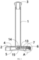
FIG. 1 is a schematic diagram showing a structure of the present invention; -
FIG. 2 is a first schematic diagram showing a longitudinal section structure inFIG. 1 of the present invention; -
FIG. 3 is a schematic diagram showing an enlarged structure of a detail A inFIG. 1 of the present invention; -
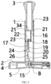
FIG. 4 is a second schematic diagram showing the longitudinal section structure inFIG. 1 of the present invention; -
FIG. 5 is a schematic diagram showing an enlarged structure of a detail B inFIG. 4 of the present invention; -
FIG. 6 is a third schematic diagram showing the longitudinal section structure inFIG. 1 of the present invention; -
FIG. 7 is a schematic diagram showing another structure of a button structure inFIG. 4 of the present invention; and -
FIG. 8 is a schematic diagram showing an enlarged structure of a detail C inFIG. 7 of the present invention. - Reference is made to
FIG. 1 to FIG. 3 , the present invention provides a technical solution: - provided is a reusable fixed tissue holder including:
- a bar frame including a
first bar frame 1 and asecond bar frame 3 sleeving thefirst bar frame 1; - a
base 2 fixed to one end of thefirst bar frame 1; - a
disc seat 4 mounted in thebase 2; - a
suction cup 5 mounted on thedisc seat 4, - wherein a
first channel 13 is disposed on thedisc seat 4, and asecond channel 15 connected with thechannel 13 is disposed on thesuction cup 5; and - a button structure mounted on the
base 2 and used for connecting thefirst channel 13 and thesecond channel 15 to the atmosphere. - Specifically, the reusable fixed tissue holder further includes a structure for exhausting a gas between the
suction cup 5 and a smooth surface when thesuction cup 5 is sucked or attached onto the smooth surface. - Specifically, the button structure includes a
button 6 mounted on the side end surface of thebase 2; anelastic element 8 is disposed between thebutton 6 and thebase 2; thedisc seat 4 is connected with a connectingpart 7 mounted in thebase 2, and the connectingpart 7 is provided with athrough groove 12 which is provided with agroove opening 11; thebutton 6 is equipped with a convexpressing block 10 of which the diameter is slightly smaller than the internal diameter of thethrough groove 12, that is, air can enter thefirst channel 13 through the groove opening 11; and thepressing block 10 is located in the throughgroove 12 and is used for plugging up the groove opening 11 at the initial time. - Specifically, a
cavity 14 is disposed between the top of thesuction cup 5 and thedisc seat 4, thefirst channel 13 and thesecond channel 15 are connected with thecavity 14, thedisc seat 4 is provided with aconvex sealing ring 28, and aring groove 27 adapted to theconvex sealing ring 28 is formed in thesuction cup 5, - In the present embodiment, during use, all the parts are mounted firstly, and then, the
second bar frame 3 is pressed so that thesuction cup 5 mounted on the bottom of thedisc seat 4 can be attached on the smooth surface such as a wall surface. At the initial time, the convexpressing block 10 on thebutton 6 may plug up thegroove opening 11 under the action of theelastic element 8, so that the throughgroove 12 may not be connected with the atmosphere. In this way, thesecond channel 15 of thesuction cup 5 is prevented from being connected with the throughgroove 12. It can be ensured that the negative pressure between the suction cup and the wall surface is in a good state after the tissue holder is fixed to the smooth wall surface, so that the overall tissue holder can be very firm and cannot be easily upset when the suction cup is sucked. If the tissue holder needs to be moved, that is, if the tissue holder needs to be dismounted from an original position and mounted on other wall surface structures, thebutton 6 of thebase 2 is pressed down to cause thesecond channel 15 to be connected with the atmosphere after passing through thefirst channel 13 and the throughgroove 12, in this way, thesuction cup 5 loses a suction force, the overall tissue holder may easily move, when the tissue holder is placed on a target place again, thebutton 6 is pressed down again, and thus, thesuction cup 5 can be firmly fixed again. - In the present embodiment, as shown in
FIG. 5 , by prefabricating theconvex sealing ring 28 on thedisc seat 4 and reserving thering groove 27 on thesuction cup 5, theconvex sealing ring 28 may be tightly attached to thering groove 27 after thesuction cup 5 and thedisc seat 4 are mounted, so that the sealing property of the suction cup 5 (the second channel 15) and the atmosphere (the first channel 13) can be improved. - In the present embodiment, when being released, the
button 6 is turned off to block the flow of air, so that thesuction cup 5 is fixed; and when being pressed down, thebutton 6 is turned on to achieve the flow of the air, so that thesuction cup 5 is unlocked. Thebutton 6 controls thefirst channel 13 to be connected with the bottom of the suction cup 5 (the second channel 15), and thus, if the button is turned on, the flow of the air is achieved, and thesuction cup 5 is unlocked. That is, if the button is turned on, the flow of the air is achieved, and thesuction cup 5 is rapidly unlocked. - In the present embodiment, the size of the overall tissue holder, sizes of the parts and the like can be set according to actual use conditions. For example, the internal diameter of the
first channel 13 and the internal diameter of thesecond channel 15 can be set according to adsorption capacity. Again for example, theelastic element 8 may adopt a reset spring, the bar frame may be made of stainless steel or PVC, theconvex sealing ring 28 may be made of the same material as thesuction cup 5, they can be flexibly selected according to specific conditions, the descriptions thereof are omitted herein. - Reference is made to
FIG. 4 , the structure in the present embodiment is basically same as the structure in theembodiment 1, except that:
the structure includes anopen pipe barrel 19 and arubber plug 20 matched with thepipe barrel 19; thepipe barrel 19 is connected with thesecond channel 15 by apipeline 25 on which a one-way valve 26 is disposed; and by pressing thesecond bar frame 3, thepipe barrel 19 generates a negative pressure between thesuction cup 5 and the smooth surface by thesecond channel 15. The inside of thefirst bar frame 1 is hollow; thesecond bar frame 3 is movably inserted to thefirst bar frame 1; thepipe barrel 19 is mounted in thefirst bar frame 1; and thesecond bar frame 3 makes thepipe barrel 19 generate a negative pressure by a linkage mechanism. The linkage mechanism includes afirst rack 16, asecond rack 17 and agear 18; one end of thefirst rack 16 is connected with the bottom end of thesecond bar frame 3, and the other end of thefirst rack 16 is engaged with thegear 18 mounted in thefirst bar frame 1; and one end of thesecond rack 17 is engaged with thegear 18, and the other end of thesecond rack 17 is connected with therubber plug 20. A slidingchute 21 is formed in the inner wall of thefirst bar frame 1, a slidingblock 23 of thesecond bar frame 3 is slidably connected with the slidingchute 21; a supportingbar 22 is mounted on thesecond rack 17 located outside thepipe barrel 19; the slidingblock 23 of the supportingbar 22 is slidably connected with the slidingchute 21; an exhaust hole (unshown in the figure) is reserved in the bottom of thepipe barrel 19; and one end of aplug lid 24 passes through thefirst bar frame 1 to plug up the exhaust hole. - In the present embodiment, the purpose of rapidly unlocking the
suction cup 5 in the above-mentionedembodiment 1 can be achieved. In addition, by additionally providing the linkage mechanism, the tissue holder may be pressed on a wall body, so that the effort is saved, and adsorption and fixation to the smooth wall surface can be more rapidly achieved without pressing for an overlarge number of times within the same time, that is, the fixation efficiency of thesuction cup 5 is higher. - In the present embodiment, the
first bar frame 1 and thesecond bar frame 3 are set to relatively slide, that is, thesecond bar frame 3 may slide along thefirst bar frame 1 by pressing the head of thesecond bar frame 3 during pressing. - In the present embodiment, as shown in
FIG. 4 , during special use, firstly, the head of thesecond bar frame 3 is pressed, in this way, the bottom end of thesecond bar frame 3 drives thefirst rack 16 to make thegear 18 rotate, thegear 18 is engaged with thesecond rack 17, then, therubber plug 20 is uplifted by thesecond rack 17, thecavity 14 is exhausted by thepipe barrel 19 to form a negative pressure, and then, a negative pressure can be rapidly achieved between thesuction cup 5 and a wall surface to be attached and fixed thereto, and thus, the tissue holder can be attached on the wall surface without applying a great pressing force. Moreover, by using the active negative pressure, not only can thesuction cup 5 be rapidly attached, but also the purposes of adsorption and fixation can be achieved by the least pressing number of times. Meanwhile, the air in a region between the suction cup and the wall surface can be evacuated as much as possible to form vacuum, so that the adsorption capacity is high, the adsorption and fixation effects are better, and as a whole, both time and effort are saved during adsorption and fixation. The purpose of attaching thesuction cup 5 is achieved by the negative pressure generated by the linkage mechanism, and thus, the effects of attaching and fixing the tissue holder on the wall surface cannot be limited by a different size of thesuction cup 5. - In the present embodiment, in order to ensure the sliding of the
second bar frame 3 on thefirst bar frame 1 and the stability that thesecond rack 17 drives therubber plug 20 to run, the slidingchute 21 is formed in the inner wall of thefirst bar frame 1, and then, the corresponding slidingblock 23 is slidably matched with the slidingchute 21, so that the above-mentioned stability is achieved. - In the present embodiment, when the suction cup is dismounted, as mentioned in the above-mentioned
embodiment 1, thebutton 6 is only pressed. Then, theplug lid 24 is pulled out, then, thesecond bar frame 3 is upwards pulled relative to thefirst bar frame 1, and thus, reset is achieved. After reset, theplug lid 24 is plugged again. Aninsertion hole 34 allowing the top end of thesecond rack 17 to be inserted is formed in the bottom of thesecond bar frame 3, so that thefirst rack 16, thegear 18, thesecond rack 17 and the like may be normally linked when being pressed by thesecond bar frame 3. - Reference is made to
FIG. 6 , the structure in the present embodiment is basically same as the structure in theembodiment 2, except that:
apush bar 31 is connected to the bottom end of thesecond bar frame 3; the bottom end of thepush bar 31 is connected with the top end of thepipe barrel 19; the inside of thefirst bar frame 1 is hollow; thepipe barrel 19 is mounted in thefirst bar frame 1; and one end of afulcrum bar 29 with achannel 32 is connected with therubber plug 20, and the other end of thefulcrum bar 29 is fixed to the inner wall of thefirst bar frame 1. - Specifically, through
holes 30 connected with thechannel 32 are formed in upper and lower ends of thefulcrum bar 29, the throughhole 30 formed in the upper end is located in thepipe barrel 9, and the throughhole 30 formed in the lower end is connected with thepipeline 25; an exhaust hole connected with thechannel 32 is reserved in the bottom of thefulcrum bar 29; and one end of theplug lid 24 passes through thefirst bar frame 1 to plug up the exhaust hole. - In the present embodiment, the opening of the
pipe barrel 19 is downward and is opposite to the opening of thepipe barrel 19 in theembodiment 2. Moreover, in the present embodiment, thepipe barrel 19 may move together with thesecond bar frame 3 relative to thefirst bar frame 1, and thefulcrum bar 29 and therubber plug 20 are fixed relative to thefirst bar frame 1. - In the present embodiment, during specific use, firstly, the head of the
second bar frame 3 is pressed, in this way, the bottom end of thesecond bar frame 3 drives thepush bar 31 to drive thepipe barrel 19 to move downwards, then, air exhaust is achieved, a negative pressure is formed in thecavity 14, and thus, time-saving and effort-saving fixation of thesuction cup 5 on the wall surface to be attached and fixed can be achieved as that in the above-mentionedembodiment 2. - In the present embodiment, the structure is further simplified as comparison with that in the
embodiment 2. Moreover, theplug lid 24 is sealed with the exhaust hole of theinner channel 32 of thefulcrum bar 29, and therefore, when the suction cup is dismounted, as mentioned in the above-mentionedembodiment 1, thebutton 6 only needs to be pressed. Then, theplug lid 24 is pulled out, then, thesecond bar frame 3 is upwards pulled relative to thefirst bar frame 1, and thus, reset is achieved. After reset, theplug lid 24 is plugged again. - In the present invention, as mentioned in the above mentioned
embodiment 2 and theembodiment 3, the movement distance of thesecond bar frame 3 may be flexibly set according to a required condition, that is, in theembodiment 2, thesecond bar frame 3 moves downwards, which may not cause interference to thegear 18 and thesecond rack 17. The movement of the supportingbar 22 may not cause interference to thepipe barrel 19. In theembodiment 3, thesecond bar frame 3 moves downwards to drive thepipe barrel 19 to move downwards, which may not cause interference to theplug lid 24, and therubber plug 20 may not be separated from the opening of thepipe barrel 19 to the outside of thepipe barrel 19, the descriptions thereof are omitted herein. - Reference is made to
FIG. 8 , the structure in the present embodiment is basically same as the structure in theembodiment 1, except that:
the button structure includes abutton 6 mounted on the upper end surface of thebase 2; thedisc seat 4 is connected with a connectingpart 7 mounted in thebase 2, and the connectingpart 7 is provided with a throughgroove 12; thebutton 6 is provided with a strip-shapedpressing block 10 passing through thebase 2 and the connectingpart 7; thepressing block 10 located in the throughgroove 12 is equipped with anelastic element 8; thepressing block 10 is provided with a rectangular or [-shapedchannel 33; ananti-drop block 9 is disposed on the bottom of thepressing block 10; and an opening in the upper end of therectangular channel 33 is connected with the atmosphere at the initial time, and an opening at the lower end of therectangular channel 33 is sealed together with the inner wall of the connectingpart 7 so that the throughgroove 12 is not connected with the atmosphere. - In the present embodiment, the mounting position of the button structure is changed from the side end surface of the
base 2 in theembodiment 1 to the upper end surface of thebase 2. The purpose of such setting is that in combination with theembodiment 2 and theembodiment 3, the button structure is mounted on the side end surface of thebase 2, the tissue holder may be pressed on the wall surface by using the linkage mechanism, so that the effort is saved, and thesuction cup 5 may be attached and fixed to the wall surface to be mounted without pressing for an overlarge number of times. However, when thesecond bar frame 3 is pressed, the linkage mechanism works, in this process, a negative pressure is formed in thecavity 14; however, after the negative pressure is formed in thecavity 14, thefirst channel 13 is connected with the throughgroove 12, and therefore, a force needs to be applied to theelastic element 8 in the negative pressure formation process. However, in order to keep a state that thegroove opening 11 of the throughgroove 12 is plugged up by thepressing block 10, it is necessary to select theelastic element 8 with a reasonable elastic coefficient to resist to an acting force generated by the negative pressure, which may cause a larger elastic coefficient of theelastic element 8, thereby being not beneficial to the pressing of thebutton 6. Therefore, the mounting position of a mechanism such as thebutton 6 is changed to the upper end surface of thebase 2, in this way, the problem can be avoided. - As shown in
FIG. 7 , thepressing block 10 moves downwards only when thebutton 6 is pressed again, which causes the opening in the upper end of therectangular channel 33 therein to be located outside the inner wall of the connectingpart 7 and the opening in the lower end of therectangular channel 33 to be located in the inner wall of the connectingpart 7, and thus, the purpose of connecting the throughgroove 12 to the atmosphere can be achieved through therectangular channel 33. When the pressing force of thebutton 6 is removed, the throughgroove 12 can be isolated again from the atmosphere by theelastic element 8 sleeving thepressing block 10 in the throughgroove 12, so that the tissue holder can be used after being dismounted next time.
Claims (11)
- A reusable fixed tissue holder, comprising:a bar frame comprising a first bar frame (1) and a second bar frame (3) sleeving the first bar frame (1);a base (2) fixed to one end of the first bar frame (1);a disc seat (4) mounted in the base (2);a suction cup (5) mounted on the disc seat (4),characterised in thata first channel (13) is disposed on the disc seat (4), and a second channel (15) connected with the channel (13) is disposed on the suction cup (5); anda button structure mounted on the base (2) and used for connecting the first channel (13) and the second channel (15) to the atmosphere.
- The tissue holder of claim 1, further comprising a structure for exhausting a gas between the suction cup (5) and a smooth surface when the suction cup (5) is attached onto the smooth surface.
- The tissue holder of claim 2, wherein the structure comprises an open pipe barrel (19) and a rubber plug (20) matched with the pipe barrel (19); the pipe barrel (19) is connected with the second channel (15) by a pipeline (25) on which a one-way valve (26) is disposed; and by pressing the second bar frame (3), the pipe barrel (19) generates a negative pressure between the suction cup (5) and the smooth surface by the second channel (15).
- The tissue holder of claim 3, wherein the inside of the first bar frame (1) is hollow; the second bar frame (3) is movably inserted to the first bar frame (1), the pipe barrel (19) is mounted in the first bar frame (1); and the second bar frame (3) makes the pipe barrel (19) generate a negative pressure by a linkage mechanism.
- The tissue holder of claim 4, wherein the linkage mechanism comprises a first rack (16), a second rack (17) and a gear (18); one end of the first rack (16) is connected with the bottom end of the second bar frame (3), and the other end of the first rack (16) is engaged with the gear (18) mounted in the first bar frame (1); and one end of the second rack (17) is engaged with the gear (18), and the other end of the second rack (17) is connected with the rubber plug (20).
- The tissue holder of claim 5, wherein a sliding chute (21) is formed in the inner wall of the first bar frame (1); a sliding block (23) of the second bar frame (3) is slidably connected with the sliding chute (21); a supporting bar (22) is mounted on the second rack (17) located outside the pipe barrel (19); the sliding block (23) of the supporting bar (22) is slidably connected with the sliding chute (21); an exhaust hole is reserved in the bottom of the pipe barrel (19); and one end of a plug lid (24) passes through the first bar frame (1) to plug up the exhaust hole.
- The tissue holder of claim 3, wherein a push bar (31) is connected to the bottom end of the second bar frame (3); the bottom end of the push bar (31) is connected with the top end of the pipe barrel (19); the inside of the first bar frame (1) is hollow; the pipe barrel (19) is mounted in the first bar frame (1); and one end of a fulcrum bar (29) with a channel (32) is connected with the rubber plug (20), and the other end of the fulcrum bar (29) is fixed to the inner wall of the first bar frame (1).
- The tissue holder of claim 7, wherein through holes (30) connected with the channel (32) are formed in upper and lower ends of the fulcrum bar (29), the through hole (30) formed in the upper end is located in the pipe barrel (9), and the through hole (30) formed in the lower end is connected with the pipeline (25); an exhaust hole connected with the channel (32) is reserved in the bottom of the fulcrum bar (29); and one end of the plug lid (24) passes through the first bar frame (1) to plug up the exhaust hole.
- The tissue holder of claim 1, wherein the button structure comprises a button (6) mounted on the side end surface of the base (2); an elastic element (8) is disposed between the button (6) and the base (2); the disc seat (4) is connected with a connecting part (7) mounted in the base (2), and the connecting part (7) is provided with a through groove (12) which is provided with a groove opening (11); the button (6) is equipped with a convex pressing block (10) of which the diameter is slightly smaller than the internal diameter of the through groove (12), that is, air can enter the first channel (13) through the groove opening (11); and the pressing block (10) is located in the through groove (12) and is used for plugging up the groove opening (11) at the initial time.
- The tissue holder of claim 1, wherein the button structure comprises a button (6) mounted on the upper end surface of the base (2); the disc seat (4) is connected with a connecting part (7) mounted in the base (2), and the connecting part (7) is provided with a through groove (12); the button (6) is provided with a strip-shaped pressing block (10) passing through the base (2) and the connecting part (7); the pressing block (10) located in the through groove (12) is equipped with an elastic element (8); the pressing block (10) is provided with a rectangular channel (33); an anti-drop block (9) is disposed on the bottom of the pressing block (10); and an opening in the upper end of the rectangular channel (33) is connected with the atmosphere at the initial time, and an opening at the lower end of the rectangular channel (33) is sealed together with the inner wall of the connecting part (7) so that the through groove (12) is not connected with the atmosphere.
- The tissue holder of claim 1, wherein a cavity (14) is disposed between the top of the suction cup (5) and the disc seat (4), the first channel (13) and the second channel (15) are connected with the cavity (14), the disc seat (4) is provided with a convex sealing ring (28), and a ring groove (27) adapted to the convex sealing ring (28) is formed in the suction cup (5).
Applications Claiming Priority (1)
| Application Number | Priority Date | Filing Date | Title |
|---|---|---|---|
| CN202210262588.2A CN114521822A (en) | 2022-03-17 | 2022-03-17 | Reusable fixed tissue holder |
Publications (2)
| Publication Number | Publication Date |
|---|---|
| EP4245200A1 EP4245200A1 (en) | 2023-09-20 |
| EP4245200B1 true EP4245200B1 (en) | 2023-12-06 |
Family
ID=81325312
Family Applications (1)
| Application Number | Title | Priority Date | Filing Date |
|---|---|---|---|
| EP22166439.4A Active EP4245200B1 (en) | 2022-03-17 | 2022-04-04 | Reusable fixed tissue holder |
Country Status (3)
| Country | Link |
|---|---|
| US (1) | US11712137B1 (en) |
| EP (1) | EP4245200B1 (en) |
| CN (1) | CN114521822A (en) |
Families Citing this family (4)
| Publication number | Priority date | Publication date | Assignee | Title |
|---|---|---|---|---|
| USD1028560S1 (en) * | 2022-04-29 | 2024-05-28 | Everyday Solutions LLC | Combined paper towel holder and spray bottle |
| USD1067674S1 (en) * | 2022-08-03 | 2025-03-25 | Ototo Design Ltd | Paper roll holder |
| USD1074252S1 (en) * | 2023-01-11 | 2025-05-13 | Qing Liu | Paper towel holder |
| US20260083287A1 (en) * | 2024-09-20 | 2026-03-26 | Yen-Lin Lin | Paper towel holder |
Family Cites Families (23)
| Publication number | Priority date | Publication date | Assignee | Title |
|---|---|---|---|---|
| US3240461A (en) * | 1963-11-22 | 1966-03-15 | Singleton Alan Martin | Suction devices |
| US4012007A (en) * | 1975-08-01 | 1977-03-15 | Cunningham Donald W | Paper towel holder |
| US4593947A (en) * | 1984-08-30 | 1986-06-10 | Yocum Roderick E | Vacuum lifting device |
| US5297750A (en) * | 1992-12-16 | 1994-03-29 | Hunt Jack E | Holder for rolls of material |
| US6405973B1 (en) * | 2000-06-02 | 2002-06-18 | Kv And F Metal Products, Inc. | Disposable towel holder |
| US6837852B2 (en) * | 2002-06-28 | 2005-01-04 | Ethicon, Inc. | Control valve for suction device for surgical applications |
| US6776368B1 (en) * | 2003-02-14 | 2004-08-17 | Creative Bath Products, Inc. | Paper towel holder |
| US20060284001A1 (en) * | 2005-06-16 | 2006-12-21 | Design For Living, L.L.C. | Roll holder and dispenser for paper products |
| HK1081054A2 (en) * | 2005-12-22 | 2006-05-04 | 高峰制品实业有限公司 | Sucker tissue holder |
| DE102006058027B4 (en) * | 2005-12-22 | 2009-07-09 | Ko Fung Products Industrial Ltd., Kwai Chung | Paper towels holder |
| US7458541B1 (en) * | 2007-06-18 | 2008-12-02 | Tai-In Chang | Tissue roll holder |
| CN202859004U (en) * | 2012-09-16 | 2013-04-10 | 赵晓 | Novel hanging rod |
| CN103101795B (en) | 2013-01-08 | 2016-01-13 | 金红叶纸业集团有限公司 | Extraction type folding tissue production equipment and process and extraction type folding tissue |
| TWM467755U (en) * | 2013-08-28 | 2013-12-11 | Mas Automation Corp | Suction device and suction tool |
| CN107280559B (en) | 2016-03-31 | 2021-03-26 | 金红叶纸业集团有限公司 | Removable Folding Tissues and Tissue Supplies |
| IT201600078303A1 (en) | 2016-07-26 | 2018-01-26 | Omet Srl | Feeding unit for a machine for converting a strip of two-ply material. |
| CN206711555U (en) * | 2017-04-21 | 2017-12-05 | 天津中德应用技术大学 | The convenient installation rack for advertising words of sucked type |
| CN207352354U (en) * | 2017-11-15 | 2018-05-11 | 青岛大学附属医院 | A kind of quick film picture-taking device |
| CN208491938U (en) * | 2018-02-07 | 2019-02-15 | 连云港浩森矿产品有限公司 | A kind of roll paper towel fixed structure |
| US10753384B1 (en) * | 2019-02-07 | 2020-08-25 | Ten Sheng Assorted Houseware Co., Ltd. | Suction cup |
| CN111486167A (en) * | 2019-11-19 | 2020-08-04 | 晋江一岂科技有限公司 | Vacuum adsorption device |
| CN212489721U (en) * | 2019-12-30 | 2021-02-09 | 江门市富成金属制品有限公司 | Paper towel holder with suction cup |
| US11391754B1 (en) * | 2020-08-26 | 2022-07-19 | Nav-Aids Ltd | Aircraft static port leech |
-
2022
- 2022-03-17 CN CN202210262588.2A patent/CN114521822A/en active Pending
- 2022-04-04 EP EP22166439.4A patent/EP4245200B1/en active Active
- 2022-04-05 US US17/713,245 patent/US11712137B1/en active Active
Also Published As
| Publication number | Publication date |
|---|---|
| CN114521822A (en) | 2022-05-24 |
| US11712137B1 (en) | 2023-08-01 |
| EP4245200A1 (en) | 2023-09-20 |
Similar Documents
| Publication | Publication Date | Title |
|---|---|---|
| EP4245200A1 (en) | Reusable fixed tissue holder | |
| JP3933420B2 (en) | Storage bag exhaust valve | |
| JP4252750B2 (en) | Hygienic new candy products | |
| CA2134568C (en) | Closure device | |
| US6604634B2 (en) | Receiving bag with enhanced airtight effect | |
| US5540557A (en) | Vacuum pump for containers | |
| US7793899B2 (en) | Structure for a suction device | |
| EP0714623A1 (en) | Heat-insulating cooking container | |
| US7571748B2 (en) | Vacuum container | |
| CN107207155A (en) | Container for storing a variety of flexible bag assemblies | |
| FR2485655A1 (en) | CLAMP FOR RETAINING A MOLDING AROUND ICE IN A MOTOR OR SIMILAR | |
| KR20200038888A (en) | Elements for activating flow-blocking valves in filtration systems with replaceable cartridges | |
| CN115366770A (en) | Button-unlocking hidden claw cup stand storage box | |
| CN209650639U (en) | A kind of vacuum sealer with upper sealing structure | |
| US6032817A (en) | Easily attachable/detachable lid mounted container | |
| CN201078388Y (en) | Improved adsorption device | |
| CN115285521B (en) | Air valve assembly | |
| JPH0541675Y2 (en) | ||
| JP3274299B2 (en) | Trash container | |
| KR101871142B1 (en) | Rotational holder for toilet roll with button | |
| JP2019535598A (en) | Container with automatic lid opening / closing method | |
| JP4635859B2 (en) | Compression bag exhaust valve | |
| KR200230913Y1 (en) | Vacuum receptacle | |
| CN221989466U (en) | Installation components, faucets and wash basins | |
| KR200253340Y1 (en) | Vacuum receptacle |
Legal Events
| Date | Code | Title | Description |
|---|---|---|---|
| PUAI | Public reference made under article 153(3) epc to a published international application that has entered the european phase |
Free format text: ORIGINAL CODE: 0009012 |
|
| STAA | Information on the status of an ep patent application or granted ep patent |
Free format text: STATUS: REQUEST FOR EXAMINATION WAS MADE |
|
| 17P | Request for examination filed |
Effective date: 20220404 |
|
| AK | Designated contracting states |
Kind code of ref document: A1 Designated state(s): AL AT BE BG CH CY CZ DE DK EE ES FI FR GB GR HR HU IE IS IT LI LT LU LV MC MK MT NL NO PL PT RO RS SE SI SK SM TR |
|
| GRAP | Despatch of communication of intention to grant a patent |
Free format text: ORIGINAL CODE: EPIDOSNIGR1 |
|
| STAA | Information on the status of an ep patent application or granted ep patent |
Free format text: STATUS: GRANT OF PATENT IS INTENDED |
|
| GRAS | Grant fee paid |
Free format text: ORIGINAL CODE: EPIDOSNIGR3 |
|
| GRAA | (expected) grant |
Free format text: ORIGINAL CODE: 0009210 |
|
| STAA | Information on the status of an ep patent application or granted ep patent |
Free format text: STATUS: THE PATENT HAS BEEN GRANTED |
|
| RIC1 | Information provided on ipc code assigned before grant |
Ipc: A47K 10/38 20060101ALN20231003BHEP Ipc: A47K 10/22 20060101AFI20231003BHEP |
|
| INTG | Intention to grant announced |
Effective date: 20231017 |
|
| AK | Designated contracting states |
Kind code of ref document: B1 Designated state(s): AL AT BE BG CH CY CZ DE DK EE ES FI FR GB GR HR HU IE IS IT LI LT LU LV MC MK MT NL NO PL PT RO RS SE SI SK SM TR |
|
| REG | Reference to a national code |
Ref country code: GB Ref legal event code: FG4D |
|
| REG | Reference to a national code |
Ref country code: CH Ref legal event code: EP |
|
| REG | Reference to a national code |
Ref country code: DE Ref legal event code: R096 Ref document number: 602022001202 Country of ref document: DE |
|
| REG | Reference to a national code |
Ref country code: IE Ref legal event code: FG4D |
|
| REG | Reference to a national code |
Ref country code: LT Ref legal event code: MG9D |
|
| PG25 | Lapsed in a contracting state [announced via postgrant information from national office to epo] |
Ref country code: GR Free format text: LAPSE BECAUSE OF FAILURE TO SUBMIT A TRANSLATION OF THE DESCRIPTION OR TO PAY THE FEE WITHIN THE PRESCRIBED TIME-LIMIT Effective date: 20240307 |
|
| REG | Reference to a national code |
Ref country code: NL Ref legal event code: MP Effective date: 20231206 |
|
| PG25 | Lapsed in a contracting state [announced via postgrant information from national office to epo] |
Ref country code: LT Free format text: LAPSE BECAUSE OF FAILURE TO SUBMIT A TRANSLATION OF THE DESCRIPTION OR TO PAY THE FEE WITHIN THE PRESCRIBED TIME-LIMIT Effective date: 20231206 |
|
| PG25 | Lapsed in a contracting state [announced via postgrant information from national office to epo] |
Ref country code: ES Free format text: LAPSE BECAUSE OF FAILURE TO SUBMIT A TRANSLATION OF THE DESCRIPTION OR TO PAY THE FEE WITHIN THE PRESCRIBED TIME-LIMIT Effective date: 20231206 |
|
| PG25 | Lapsed in a contracting state [announced via postgrant information from national office to epo] |
Ref country code: LT Free format text: LAPSE BECAUSE OF FAILURE TO SUBMIT A TRANSLATION OF THE DESCRIPTION OR TO PAY THE FEE WITHIN THE PRESCRIBED TIME-LIMIT Effective date: 20231206 Ref country code: GR Free format text: LAPSE BECAUSE OF FAILURE TO SUBMIT A TRANSLATION OF THE DESCRIPTION OR TO PAY THE FEE WITHIN THE PRESCRIBED TIME-LIMIT Effective date: 20240307 Ref country code: ES Free format text: LAPSE BECAUSE OF FAILURE TO SUBMIT A TRANSLATION OF THE DESCRIPTION OR TO PAY THE FEE WITHIN THE PRESCRIBED TIME-LIMIT Effective date: 20231206 Ref country code: BG Free format text: LAPSE BECAUSE OF FAILURE TO SUBMIT A TRANSLATION OF THE DESCRIPTION OR TO PAY THE FEE WITHIN THE PRESCRIBED TIME-LIMIT Effective date: 20240306 |
|
| REG | Reference to a national code |
Ref country code: AT Ref legal event code: MK05 Ref document number: 1637571 Country of ref document: AT Kind code of ref document: T Effective date: 20231206 |
|
| PG25 | Lapsed in a contracting state [announced via postgrant information from national office to epo] |
Ref country code: NL Free format text: LAPSE BECAUSE OF FAILURE TO SUBMIT A TRANSLATION OF THE DESCRIPTION OR TO PAY THE FEE WITHIN THE PRESCRIBED TIME-LIMIT Effective date: 20231206 |
|
| PG25 | Lapsed in a contracting state [announced via postgrant information from national office to epo] |
Ref country code: SE Free format text: LAPSE BECAUSE OF FAILURE TO SUBMIT A TRANSLATION OF THE DESCRIPTION OR TO PAY THE FEE WITHIN THE PRESCRIBED TIME-LIMIT Effective date: 20231206 Ref country code: RS Free format text: LAPSE BECAUSE OF FAILURE TO SUBMIT A TRANSLATION OF THE DESCRIPTION OR TO PAY THE FEE WITHIN THE PRESCRIBED TIME-LIMIT Effective date: 20231206 Ref country code: NO Free format text: LAPSE BECAUSE OF FAILURE TO SUBMIT A TRANSLATION OF THE DESCRIPTION OR TO PAY THE FEE WITHIN THE PRESCRIBED TIME-LIMIT Effective date: 20240306 Ref country code: NL Free format text: LAPSE BECAUSE OF FAILURE TO SUBMIT A TRANSLATION OF THE DESCRIPTION OR TO PAY THE FEE WITHIN THE PRESCRIBED TIME-LIMIT Effective date: 20231206 Ref country code: LV Free format text: LAPSE BECAUSE OF FAILURE TO SUBMIT A TRANSLATION OF THE DESCRIPTION OR TO PAY THE FEE WITHIN THE PRESCRIBED TIME-LIMIT Effective date: 20231206 Ref country code: HR Free format text: LAPSE BECAUSE OF FAILURE TO SUBMIT A TRANSLATION OF THE DESCRIPTION OR TO PAY THE FEE WITHIN THE PRESCRIBED TIME-LIMIT Effective date: 20231206 |
|
| PG25 | Lapsed in a contracting state [announced via postgrant information from national office to epo] |
Ref country code: IS Free format text: LAPSE BECAUSE OF FAILURE TO SUBMIT A TRANSLATION OF THE DESCRIPTION OR TO PAY THE FEE WITHIN THE PRESCRIBED TIME-LIMIT Effective date: 20240406 |
|
| PG25 | Lapsed in a contracting state [announced via postgrant information from national office to epo] |
Ref country code: CZ Free format text: LAPSE BECAUSE OF FAILURE TO SUBMIT A TRANSLATION OF THE DESCRIPTION OR TO PAY THE FEE WITHIN THE PRESCRIBED TIME-LIMIT Effective date: 20231206 Ref country code: AT Free format text: LAPSE BECAUSE OF FAILURE TO SUBMIT A TRANSLATION OF THE DESCRIPTION OR TO PAY THE FEE WITHIN THE PRESCRIBED TIME-LIMIT Effective date: 20231206 |
|
| PG25 | Lapsed in a contracting state [announced via postgrant information from national office to epo] |
Ref country code: SK Free format text: LAPSE BECAUSE OF FAILURE TO SUBMIT A TRANSLATION OF THE DESCRIPTION OR TO PAY THE FEE WITHIN THE PRESCRIBED TIME-LIMIT Effective date: 20231206 |
|
| PG25 | Lapsed in a contracting state [announced via postgrant information from national office to epo] |
Ref country code: SM Free format text: LAPSE BECAUSE OF FAILURE TO SUBMIT A TRANSLATION OF THE DESCRIPTION OR TO PAY THE FEE WITHIN THE PRESCRIBED TIME-LIMIT Effective date: 20231206 Ref country code: SK Free format text: LAPSE BECAUSE OF FAILURE TO SUBMIT A TRANSLATION OF THE DESCRIPTION OR TO PAY THE FEE WITHIN THE PRESCRIBED TIME-LIMIT Effective date: 20231206 Ref country code: RO Free format text: LAPSE BECAUSE OF FAILURE TO SUBMIT A TRANSLATION OF THE DESCRIPTION OR TO PAY THE FEE WITHIN THE PRESCRIBED TIME-LIMIT Effective date: 20231206 Ref country code: IT Free format text: LAPSE BECAUSE OF FAILURE TO SUBMIT A TRANSLATION OF THE DESCRIPTION OR TO PAY THE FEE WITHIN THE PRESCRIBED TIME-LIMIT Effective date: 20231206 Ref country code: IS Free format text: LAPSE BECAUSE OF FAILURE TO SUBMIT A TRANSLATION OF THE DESCRIPTION OR TO PAY THE FEE WITHIN THE PRESCRIBED TIME-LIMIT Effective date: 20240406 Ref country code: EE Free format text: LAPSE BECAUSE OF FAILURE TO SUBMIT A TRANSLATION OF THE DESCRIPTION OR TO PAY THE FEE WITHIN THE PRESCRIBED TIME-LIMIT Effective date: 20231206 Ref country code: CZ Free format text: LAPSE BECAUSE OF FAILURE TO SUBMIT A TRANSLATION OF THE DESCRIPTION OR TO PAY THE FEE WITHIN THE PRESCRIBED TIME-LIMIT Effective date: 20231206 Ref country code: AT Free format text: LAPSE BECAUSE OF FAILURE TO SUBMIT A TRANSLATION OF THE DESCRIPTION OR TO PAY THE FEE WITHIN THE PRESCRIBED TIME-LIMIT Effective date: 20231206 |
|
| PG25 | Lapsed in a contracting state [announced via postgrant information from national office to epo] |
Ref country code: PL Free format text: LAPSE BECAUSE OF FAILURE TO SUBMIT A TRANSLATION OF THE DESCRIPTION OR TO PAY THE FEE WITHIN THE PRESCRIBED TIME-LIMIT Effective date: 20231206 Ref country code: PT Free format text: LAPSE BECAUSE OF FAILURE TO SUBMIT A TRANSLATION OF THE DESCRIPTION OR TO PAY THE FEE WITHIN THE PRESCRIBED TIME-LIMIT Effective date: 20240408 |
|
| PG25 | Lapsed in a contracting state [announced via postgrant information from national office to epo] |
Ref country code: PT Free format text: LAPSE BECAUSE OF FAILURE TO SUBMIT A TRANSLATION OF THE DESCRIPTION OR TO PAY THE FEE WITHIN THE PRESCRIBED TIME-LIMIT Effective date: 20240408 Ref country code: PL Free format text: LAPSE BECAUSE OF FAILURE TO SUBMIT A TRANSLATION OF THE DESCRIPTION OR TO PAY THE FEE WITHIN THE PRESCRIBED TIME-LIMIT Effective date: 20231206 |
|
| REG | Reference to a national code |
Ref country code: DE Ref legal event code: R097 Ref document number: 602022001202 Country of ref document: DE |
|
| PG25 | Lapsed in a contracting state [announced via postgrant information from national office to epo] |
Ref country code: DK Free format text: LAPSE BECAUSE OF FAILURE TO SUBMIT A TRANSLATION OF THE DESCRIPTION OR TO PAY THE FEE WITHIN THE PRESCRIBED TIME-LIMIT Effective date: 20231206 |
|
| PLBE | No opposition filed within time limit |
Free format text: ORIGINAL CODE: 0009261 |
|
| STAA | Information on the status of an ep patent application or granted ep patent |
Free format text: STATUS: NO OPPOSITION FILED WITHIN TIME LIMIT |
|
| PG25 | Lapsed in a contracting state [announced via postgrant information from national office to epo] |
Ref country code: SI Free format text: LAPSE BECAUSE OF FAILURE TO SUBMIT A TRANSLATION OF THE DESCRIPTION OR TO PAY THE FEE WITHIN THE PRESCRIBED TIME-LIMIT Effective date: 20231206 |
|
| PG25 | Lapsed in a contracting state [announced via postgrant information from national office to epo] |
Ref country code: SI Free format text: LAPSE BECAUSE OF FAILURE TO SUBMIT A TRANSLATION OF THE DESCRIPTION OR TO PAY THE FEE WITHIN THE PRESCRIBED TIME-LIMIT Effective date: 20231206 Ref country code: DK Free format text: LAPSE BECAUSE OF FAILURE TO SUBMIT A TRANSLATION OF THE DESCRIPTION OR TO PAY THE FEE WITHIN THE PRESCRIBED TIME-LIMIT Effective date: 20231206 |
|
| REG | Reference to a national code |
Ref country code: DE Ref legal event code: R119 Ref document number: 602022001202 Country of ref document: DE |
|
| 26N | No opposition filed |
Effective date: 20240909 |
|
| PG25 | Lapsed in a contracting state [announced via postgrant information from national office to epo] |
Ref country code: MC Free format text: LAPSE BECAUSE OF FAILURE TO SUBMIT A TRANSLATION OF THE DESCRIPTION OR TO PAY THE FEE WITHIN THE PRESCRIBED TIME-LIMIT Effective date: 20231206 |
|
| PG25 | Lapsed in a contracting state [announced via postgrant information from national office to epo] |
Ref country code: MC Free format text: LAPSE BECAUSE OF FAILURE TO SUBMIT A TRANSLATION OF THE DESCRIPTION OR TO PAY THE FEE WITHIN THE PRESCRIBED TIME-LIMIT Effective date: 20231206 |
|
| PG25 | Lapsed in a contracting state [announced via postgrant information from national office to epo] |
Ref country code: LU Free format text: LAPSE BECAUSE OF NON-PAYMENT OF DUE FEES Effective date: 20240404 |
|
| REG | Reference to a national code |
Ref country code: BE Ref legal event code: MM Effective date: 20240430 |
|
| PG25 | Lapsed in a contracting state [announced via postgrant information from national office to epo] |
Ref country code: LU Free format text: LAPSE BECAUSE OF NON-PAYMENT OF DUE FEES Effective date: 20240404 |
|
| PG25 | Lapsed in a contracting state [announced via postgrant information from national office to epo] |
Ref country code: DE Free format text: LAPSE BECAUSE OF NON-PAYMENT OF DUE FEES Effective date: 20241105 |
|
| PG25 | Lapsed in a contracting state [announced via postgrant information from national office to epo] |
Ref country code: BE Free format text: LAPSE BECAUSE OF NON-PAYMENT OF DUE FEES Effective date: 20240430 |
|
| PG25 | Lapsed in a contracting state [announced via postgrant information from national office to epo] |
Ref country code: FR Free format text: LAPSE BECAUSE OF NON-PAYMENT OF DUE FEES Effective date: 20240430 |
|
| PG25 | Lapsed in a contracting state [announced via postgrant information from national office to epo] |
Ref country code: FR Free format text: LAPSE BECAUSE OF NON-PAYMENT OF DUE FEES Effective date: 20240430 Ref country code: DE Free format text: LAPSE BECAUSE OF NON-PAYMENT OF DUE FEES Effective date: 20241105 Ref country code: BE Free format text: LAPSE BECAUSE OF NON-PAYMENT OF DUE FEES Effective date: 20240430 |
|
| PG25 | Lapsed in a contracting state [announced via postgrant information from national office to epo] |
Ref country code: IE Free format text: LAPSE BECAUSE OF NON-PAYMENT OF DUE FEES Effective date: 20240404 |
|
| PG25 | Lapsed in a contracting state [announced via postgrant information from national office to epo] |
Ref country code: CY Free format text: LAPSE BECAUSE OF FAILURE TO SUBMIT A TRANSLATION OF THE DESCRIPTION OR TO PAY THE FEE WITHIN THE PRESCRIBED TIME-LIMIT; INVALID AB INITIO Effective date: 20220404 |
|
| PG25 | Lapsed in a contracting state [announced via postgrant information from national office to epo] |
Ref country code: FI Free format text: LAPSE BECAUSE OF FAILURE TO SUBMIT A TRANSLATION OF THE DESCRIPTION OR TO PAY THE FEE WITHIN THE PRESCRIBED TIME-LIMIT Effective date: 20231207 |
|
| REG | Reference to a national code |
Ref country code: CH Ref legal event code: H13 Free format text: ST27 STATUS EVENT CODE: U-0-0-H10-H13 (AS PROVIDED BY THE NATIONAL OFFICE) Effective date: 20251125 |
|
| PG25 | Lapsed in a contracting state [announced via postgrant information from national office to epo] |
Ref country code: TR Free format text: LAPSE BECAUSE OF FAILURE TO SUBMIT A TRANSLATION OF THE DESCRIPTION OR TO PAY THE FEE WITHIN THE PRESCRIBED TIME-LIMIT Effective date: 20231206 |
|
| PG25 | Lapsed in a contracting state [announced via postgrant information from national office to epo] |
Ref country code: CH Free format text: LAPSE BECAUSE OF NON-PAYMENT OF DUE FEES Effective date: 20250430 |