EP4245177A2 - Dispositif agencé pour chauffer une substance à fumer et procédé de formation du dispositif chauffant - Google Patents
Dispositif agencé pour chauffer une substance à fumer et procédé de formation du dispositif chauffant Download PDFInfo
- Publication number
- EP4245177A2 EP4245177A2 EP23182510.0A EP23182510A EP4245177A2 EP 4245177 A2 EP4245177 A2 EP 4245177A2 EP 23182510 A EP23182510 A EP 23182510A EP 4245177 A2 EP4245177 A2 EP 4245177A2
- Authority
- EP
- European Patent Office
- Prior art keywords
- heater
- smokable material
- housing
- hollow
- heat
- Prior art date
- Legal status (The legal status is an assumption and is not a legal conclusion. Google has not performed a legal analysis and makes no representation as to the accuracy of the status listed.)
- Pending
Links
- 239000000463 material Substances 0.000 title claims abstract description 96
- 238000000034 method Methods 0.000 title claims description 20
- 238000010438 heat treatment Methods 0.000 claims abstract description 48
- 229920003023 plastic Polymers 0.000 claims description 23
- 239000004033 plastic Substances 0.000 claims description 23
- 239000012212 insulator Substances 0.000 claims description 14
- 239000004642 Polyimide Substances 0.000 claims description 7
- 229920001721 polyimide Polymers 0.000 claims description 7
- 239000004696 Poly ether ether ketone Substances 0.000 claims description 4
- 229920002530 polyetherether ketone Polymers 0.000 claims description 4
- 229910001220 stainless steel Inorganic materials 0.000 claims description 2
- 239000010935 stainless steel Substances 0.000 claims description 2
- 241000208125 Nicotiana Species 0.000 description 15
- 235000002637 Nicotiana tabacum Nutrition 0.000 description 15
- 239000004433 Thermoplastic polyurethane Substances 0.000 description 6
- 239000000443 aerosol Substances 0.000 description 6
- 229920002803 thermoplastic polyurethane Polymers 0.000 description 6
- 239000010409 thin film Substances 0.000 description 6
- 229920001971 elastomer Polymers 0.000 description 5
- 229920000642 polymer Polymers 0.000 description 5
- 229920001296 polysiloxane Polymers 0.000 description 5
- 239000003566 sealing material Substances 0.000 description 5
- SNICXCGAKADSCV-JTQLQIEISA-N (-)-Nicotine Chemical compound CN1CCC[C@H]1C1=CC=CN=C1 SNICXCGAKADSCV-JTQLQIEISA-N 0.000 description 4
- 229960002715 nicotine Drugs 0.000 description 4
- SNICXCGAKADSCV-UHFFFAOYSA-N nicotine Natural products CN1CCCC1C1=CC=CN=C1 SNICXCGAKADSCV-UHFFFAOYSA-N 0.000 description 4
- 238000005096 rolling process Methods 0.000 description 4
- 239000000853 adhesive Substances 0.000 description 3
- 230000001070 adhesive effect Effects 0.000 description 3
- 150000001875 compounds Chemical class 0.000 description 3
- 238000001816 cooling Methods 0.000 description 3
- 239000007788 liquid Substances 0.000 description 3
- 239000000758 substrate Substances 0.000 description 3
- PXHVJJICTQNCMI-UHFFFAOYSA-N Nickel Chemical compound [Ni] PXHVJJICTQNCMI-UHFFFAOYSA-N 0.000 description 2
- 230000008901 benefit Effects 0.000 description 2
- 238000004891 communication Methods 0.000 description 2
- 238000011109 contamination Methods 0.000 description 2
- 239000003571 electronic cigarette Substances 0.000 description 2
- 238000002955 isolation Methods 0.000 description 2
- 238000004519 manufacturing process Methods 0.000 description 2
- 239000000203 mixture Substances 0.000 description 2
- 238000007789 sealing Methods 0.000 description 2
- 230000000391 smoking effect Effects 0.000 description 2
- HBBGRARXTFLTSG-UHFFFAOYSA-N Lithium ion Chemical compound [Li+] HBBGRARXTFLTSG-UHFFFAOYSA-N 0.000 description 1
- 239000004677 Nylon Substances 0.000 description 1
- 239000004820 Pressure-sensitive adhesive Substances 0.000 description 1
- 239000004676 acrylonitrile butadiene styrene Substances 0.000 description 1
- 239000002390 adhesive tape Substances 0.000 description 1
- OJIJEKBXJYRIBZ-UHFFFAOYSA-N cadmium nickel Chemical compound [Ni].[Cd] OJIJEKBXJYRIBZ-UHFFFAOYSA-N 0.000 description 1
- 235000019506 cigar Nutrition 0.000 description 1
- 235000019504 cigarettes Nutrition 0.000 description 1
- 238000004140 cleaning Methods 0.000 description 1
- 238000010276 construction Methods 0.000 description 1
- 230000000694 effects Effects 0.000 description 1
- 238000001914 filtration Methods 0.000 description 1
- 239000012530 fluid Substances 0.000 description 1
- 239000011521 glass Substances 0.000 description 1
- 239000003292 glue Substances 0.000 description 1
- 238000002347 injection Methods 0.000 description 1
- 239000007924 injection Substances 0.000 description 1
- 238000001746 injection moulding Methods 0.000 description 1
- 239000011810 insulating material Substances 0.000 description 1
- 229910001416 lithium ion Inorganic materials 0.000 description 1
- 230000007246 mechanism Effects 0.000 description 1
- 238000012986 modification Methods 0.000 description 1
- 230000004048 modification Effects 0.000 description 1
- 229910052759 nickel Inorganic materials 0.000 description 1
- 229920001778 nylon Polymers 0.000 description 1
- 238000003825 pressing Methods 0.000 description 1
- 239000000779 smoke Substances 0.000 description 1
- 239000007787 solid Substances 0.000 description 1
- 229920001169 thermoplastic Polymers 0.000 description 1
- 239000004416 thermosoftening plastic Substances 0.000 description 1
- 235000019505 tobacco product Nutrition 0.000 description 1
Images


Classifications
-
- H—ELECTRICITY
- H05—ELECTRIC TECHNIQUES NOT OTHERWISE PROVIDED FOR
- H05B—ELECTRIC HEATING; ELECTRIC LIGHT SOURCES NOT OTHERWISE PROVIDED FOR; CIRCUIT ARRANGEMENTS FOR ELECTRIC LIGHT SOURCES, IN GENERAL
- H05B3/00—Ohmic-resistance heating
- H05B3/40—Heating elements having the shape of rods or tubes
- H05B3/42—Heating elements having the shape of rods or tubes non-flexible
- H05B3/46—Heating elements having the shape of rods or tubes non-flexible heating conductor mounted on insulating base
-
- A—HUMAN NECESSITIES
- A24—TOBACCO; CIGARS; CIGARETTES; SIMULATED SMOKING DEVICES; SMOKERS' REQUISITES
- A24F—SMOKERS' REQUISITES; MATCH BOXES; SIMULATED SMOKING DEVICES
- A24F40/00—Electrically operated smoking devices; Component parts thereof; Manufacture thereof; Maintenance or testing thereof; Charging means specially adapted therefor
- A24F40/20—Devices using solid inhalable precursors
-
- A—HUMAN NECESSITIES
- A24—TOBACCO; CIGARS; CIGARETTES; SIMULATED SMOKING DEVICES; SMOKERS' REQUISITES
- A24F—SMOKERS' REQUISITES; MATCH BOXES; SIMULATED SMOKING DEVICES
- A24F40/00—Electrically operated smoking devices; Component parts thereof; Manufacture thereof; Maintenance or testing thereof; Charging means specially adapted therefor
- A24F40/40—Constructional details, e.g. connection of cartridges and battery parts
- A24F40/46—Shape or structure of electric heating means
-
- A—HUMAN NECESSITIES
- A24—TOBACCO; CIGARS; CIGARETTES; SIMULATED SMOKING DEVICES; SMOKERS' REQUISITES
- A24F—SMOKERS' REQUISITES; MATCH BOXES; SIMULATED SMOKING DEVICES
- A24F40/00—Electrically operated smoking devices; Component parts thereof; Manufacture thereof; Maintenance or testing thereof; Charging means specially adapted therefor
- A24F40/50—Control or monitoring
-
- A—HUMAN NECESSITIES
- A24—TOBACCO; CIGARS; CIGARETTES; SIMULATED SMOKING DEVICES; SMOKERS' REQUISITES
- A24F—SMOKERS' REQUISITES; MATCH BOXES; SIMULATED SMOKING DEVICES
- A24F40/00—Electrically operated smoking devices; Component parts thereof; Manufacture thereof; Maintenance or testing thereof; Charging means specially adapted therefor
- A24F40/70—Manufacture
-
- A—HUMAN NECESSITIES
- A61—MEDICAL OR VETERINARY SCIENCE; HYGIENE
- A61M—DEVICES FOR INTRODUCING MEDIA INTO, OR ONTO, THE BODY; DEVICES FOR TRANSDUCING BODY MEDIA OR FOR TAKING MEDIA FROM THE BODY; DEVICES FOR PRODUCING OR ENDING SLEEP OR STUPOR
- A61M11/00—Sprayers or atomisers specially adapted for therapeutic purposes
- A61M11/04—Sprayers or atomisers specially adapted for therapeutic purposes operated by the vapour pressure of the liquid to be sprayed or atomised
- A61M11/041—Sprayers or atomisers specially adapted for therapeutic purposes operated by the vapour pressure of the liquid to be sprayed or atomised using heaters
-
- H—ELECTRICITY
- H05—ELECTRIC TECHNIQUES NOT OTHERWISE PROVIDED FOR
- H05B—ELECTRIC HEATING; ELECTRIC LIGHT SOURCES NOT OTHERWISE PROVIDED FOR; CIRCUIT ARRANGEMENTS FOR ELECTRIC LIGHT SOURCES, IN GENERAL
- H05B3/00—Ohmic-resistance heating
- H05B3/02—Details
- H05B3/04—Waterproof or air-tight seals for heaters
-
- H—ELECTRICITY
- H05—ELECTRIC TECHNIQUES NOT OTHERWISE PROVIDED FOR
- H05B—ELECTRIC HEATING; ELECTRIC LIGHT SOURCES NOT OTHERWISE PROVIDED FOR; CIRCUIT ARRANGEMENTS FOR ELECTRIC LIGHT SOURCES, IN GENERAL
- H05B2203/00—Aspects relating to Ohmic resistive heating covered by group H05B3/00
- H05B2203/013—Heaters using resistive films or coatings
-
- H—ELECTRICITY
- H05—ELECTRIC TECHNIQUES NOT OTHERWISE PROVIDED FOR
- H05B—ELECTRIC HEATING; ELECTRIC LIGHT SOURCES NOT OTHERWISE PROVIDED FOR; CIRCUIT ARRANGEMENTS FOR ELECTRIC LIGHT SOURCES, IN GENERAL
- H05B2203/00—Aspects relating to Ohmic resistive heating covered by group H05B3/00
- H05B2203/017—Manufacturing methods or apparatus for heaters
Definitions
- the present invention relates to an apparatus arranged to heat smokable material and a method of forming a heater for apparatus arranged to heat smokable material.
- Articles such as cigarettes, cigars and the like burn tobacco during use to create tobacco smoke. Attempts have been made to provide alternatives to these types of articles, which burn tobacco, by creating products that release compounds without burning. Examples of such products are so-called heat-not-burn products, also known as tobacco heating products or tobacco heating devices, which release compounds by heating, but not burning, the material.
- the material may be for example tobacco or other non-tobacco products or a combination, such as a blended mix, which may or may not contain nicotine.
- e-cigarette devices which typically vaporise a liquid, which may or may not contain nicotine.
- apparatus arranged to heat smokable material to volatilise at least one component of said smokable material, the apparatus comprising:
- this prevents air that is in other parts of the apparatus entering the hollow central portion of the heater, and so for example prevents contamination of the air that is flowing through the air flow path created by the hollow central portion of the heater and which in use contains volatilised component(s) from the smokable material. Conversely, this also helps prevent air flow that is passing through the hollow central portion of the heater leaking into other parts of the apparatus.
- the sheet comprises a plastics layer.
- the layer is a polyimide layer.
- the apparatus comprises at least one electrically conductive track on the layer and which provides a heating element of the heater.
- the apparatus comprises a further plastics layer on the electrically conductive track such that the electrically conductive track is between the plastics layers.
- the generally planar sheet of material, which is rolled to form the heater is a multi-layered sheet made by stacking layers of polyimide and electrically conductive traces on top of one another.
- the heater is a thin film heater.
- the apparatus comprises a heat insulator surrounding the heater for reducing heat loss from the heater to the exterior of the apparatus.
- a method of forming a heater for apparatus arranged to heat smokable material to volatilise at least one component of said smokable material comprising:
- the sheet comprises a plastics layer.
- the layer is a polyimide layer.
- the method comprises forming at least one electrically conductive track on the layer prior to rolling the sheet into the hollow tube.
- the method comprises forming a further plastics layer on the electrically conductive track such that the electrically conductive track is between the plastics layers.
- the heater is a thin film heater.
- the term “smokable material” includes materials that provide volatilised components upon heating, typically in the form of an aerosol.
- “Smokable material” includes any tobacco-containing material and may, for example, include one or more of tobacco, tobacco derivatives, expanded tobacco, reconstituted tobacco or tobacco substitutes.
- “Smokable material” also may include other, non-tobacco, products, which, depending on the product, may or may not contain nicotine.
- “Smokable material” may for example be in the form of a solid, a liquid, a gel or a wax or the like.
- “Smokable material” may for example also be a combination or a blend of materials.
- Apparatus that heats smokable material to volatilise at least one component of the smokable material, typically to form an aerosol which can be inhaled, without burning or combusting the smokable material.
- Such apparatus is sometimes described as a “heat-not-burn” apparatus or a “tobacco heating product” or “tobacco heating device” or similar.
- e-cigarette devices which typically vaporise a smokable material in the form of a liquid, which may or may not contain nicotine.
- the smokable material may be in the form of or provided as part of a rod, cartridge or cassette or the like which can be inserted into the apparatus.
- a heater for heating and volatilising the smokable material may be provided as a "permanent" part of the apparatus or may be provided as part of the smoking article or consumable which is discarded and replaced after use.
- a "smoking article” in this context is a device or article or other component that includes or contains in use the smokable material, which in use is heated to volatilise the smokable material, and optionally other components.
- FIGS. 1 to 4 there are shown views of an example of an apparatus 10 arranged to heat smokable material to volatilise at least one component of said smokable material, typically to form an aerosol which can be inhaled.
- Figure 3 shows the apparatus 10 with smokable material inserted
- Figure 4 shows the apparatus 10 with no smokable material inserted.
- the apparatus 10 is a heating apparatus 10 which releases compounds by heating, but not burning, the smokable material.
- a first end 11 is sometimes referred to herein as the mouth or proximal end 11 and a second end 12 is sometimes referred to herein as the distal end 12.
- the apparatus 10 has an on/off button (not shown) to allow the apparatus 10 as a whole to be switched on and off as desired by a user.
- the apparatus 10 provides a housing for locating and protecting various internal components of the apparatus 10.
- the apparatus 10 is formed of one or more internal "chassis" parts and one or more external sleeve parts.
- the apparatus 10 has a single, unitary external sleeve or housing 14 and an internal chassis 16.
- the internal chassis 16 may be formed of two chassis halves, and optionally other chassis parts.
- the chassis or chassis parts 16 may be removably fixed to the housing 14, to permit easy access to the interior of the apparatus 10, or may be "permanently" fixed to the chassis 16, for example to deter a user from accessing the interior of the apparatus 10.
- the chassis 16 provides or supports at least in part a front wall of the apparatus 10 at the first or mouth end 11 and also provides at least in part a rear wall 18 of the apparatus at the second or distal end 12.
- the chassis 16 is made of a plastics material, including for example glass-filled nylon formed by injection moulding, though other materials and other manufacturing processes may be used.
- the housing 14 has located or fixed therein a heater 20, control circuitry 21 and a power source 22.
- the heater 20, the control circuitry 21 and the power source 22 are laterally adjacent (that is, adjacent when viewed from an end), with the control circuitry 21 being located generally between the heater 20 and the power source 22, though other locations are possible.
- the control circuitry 21 may include a controller, such as a microprocessor arrangement, configured and arranged to control the heating of the smokable material as discussed further below.
- the power source 22 may be for example a battery, which may be a rechargeable battery or a non-rechargeable battery.
- Suitable batteries include for example a lithium-ion battery, a nickel battery (such as a nickel-cadmium battery), an alkaline battery and/ or the like.
- the battery 22 is electrically coupled to the heater 20 to supply electrical power when required and under control of the control circuitry 21 to heat the smokable material (as discussed, to volatilise the smokable material without causing the smokable material to burn).
- An advantage of locating the power source 22 laterally adjacent to the heater 20 is that a physically large power source 22 may be used without causing the apparatus 20 as a whole to be unduly lengthy.
- a physically large power source 22 has a higher capacity (that is, the total electrical energy that can be supplied, often measured in Amp-hours or the like) and thus the battery life for the apparatus 10 can be longer.
- the heater 20 is generally in the form of a hollow cylindrical tube, having a hollow interior heating chamber 23 into which smokable material is inserted for heating in use.
- the heater 20 may be formed as a single heater or may be formed of plural heaters aligned along the longitudinal axis of the heater 20. (For simplicity, reference to a "heater” herein shall be taken to include plural heaters, unless the context requires otherwise.)
- the heater 20 may be annular or tubular, or at least part-annular or part-tubular around its circumference.
- the heater 20 may be a thin film heater.
- the heater 20 is supported by a stainless steel support tube.
- the heater 20 is dimensioned so that substantially the whole of the smokable material when inserted is located within the heating element(s) of the heater 20 so that substantially the whole of the smokable material is heated in use.
- the heater 20 may be arranged so that selected zones of the smokable material can be independently heated, for example in turn (over time) or together (simultaneously) as desired.
- the heater 20 in this example is surrounded along at least part of its length by a thermal insulator 24.
- the insulator 24 helps to reduce heat passing from the heater 20 to the exterior of the apparatus 10. This helps to keep down the power requirements for the heater 20 as it reduces heat losses generally.
- the insulator 24 also helps to keep the exterior of the apparatus 10 cool during operation of the heater 20.
- the insulator 24 may be a double-walled sleeve which provides a low pressure region between the two walls of the sleeve. That is, the insulator 24 may be for example a "vacuum" tube, i.e. a tube that has been at least partially evacuated so as to minimise heat transfer by conduction and/or convection.
- Other arrangements for the insulator 24 are possible, including using heat insulating materials, including for example a suitable foam-type material, in addition to or instead of a double-walled sleeve.
- the front of the chassis 16 has an opening 30 at the mouth end 11 of the apparatus 10 through which smokable material in use may be passed to be inserted into the apparatus 10 and removed from the apparatus 10 by a user.
- a door 31 is provided at the mouth end 11. The door 31 can be opened so as to allow smokable material to be passed through the opening 30 to be inserted into and removed from the apparatus 10 during periods of use and can be closed to close the opening 30 to keep the interior of the apparatus 10 clean during periods of non-use and avoiding damage to the interior of the apparatus 10.
- the door 31 in this example is a sliding door, which can be slid up and down to close and open the opening 30. In other examples, the door 31 may be a hinged door or other arrangements may be provided.
- the door 31 in this example is provided in conjunction with a front component 32.
- the front component 32 has at least one part.
- the front component 32 has three parts, a front part 32a, an intermediate part 32b and a rear part 32c.
- the intermediate part 32b may be secured to the rear part 32c for example adhesive, including for example double-sided adhesive tape.
- the front door 31 of the apparatus 10 is constructed and arranged to be slidably connected to the front component 32.
- the front door 31 may be slidably fitted to the front component 32 by a projection and recess combination.
- the front door 31 in the example shown has a rearwards facing projection 31' which is received in a recess or channel 32' in the front component 32.
- the front door 31 may be secured using a screw 32" which nevertheless allows the front door 31 to slide up and down in the channel 32'.
- this shows a rod 50 which includes smokable material 51 inserted partly through the front opening 30 so that (at least) the smokable material 51 is located within the heating chamber 23 of the heater 20 so that the smokable material 51 is heated when the heater 20 is energised.
- the rod 50 has at the mouth end a mouthpiece assembly which includes one or more of a filter for filtering aerosol and/or a cooling element 52 for cooling aerosol.
- the filter/cooling element 52 is spaced from the smokable material by a space 53 and is also spaced from the mouth end of the rod 50 by a further space 54.
- the rear wall 18 of the housing 14 has an opening 35 at the distal end 12 of the apparatus 10.
- a door 36 is provided at the distal end 12.
- the door 36 can be opened so as to allow access to the opening 35 at the distal end 12 and can be closed to close the opening 35 at the distal end 12.
- the door 36 at the distal end 12 in this example is a hinged door.
- the door 36 may be a sliding door or other arrangements may be provided.
- the hinge may be provided as a "living hinge". More preferably, the door 36 is a separate component and the hinge for the door 36 is a barrel hinge.
- the heater 20 is generally in the form of a hollow cylindrical tube is located within the chassis 16 so that one end of the hollow tube is in fluid communication with the opening 30 at the mouth end 11 and the other end of the hollow tube is in communication with the opening 35 at the distal end.
- the user closes the door 36 at the distal end 12 to close the opening 35 at the distal end 12 and opens the door 30 at the mouth end 11 to open the opening 30 at the mouth end 11.
- the user then inserts the rod 50 that includes smokable material 51 through the opening 30 at the mouth end 11 into the heating chamber 23 of the heater 20, operates the apparatus 10 to heat the smokable material 51 to generate an aerosol for inhaling as desired, and then removes the rod 50 with used smokable material 51 from the apparatus 10 through the opening 30 at the mouth end 11.
- the user can open the door 36 at the distal end 12 to open the opening 35 at the distal end 12 after the apparatus 10 has been used.
- the opening 35 at the distal end 12 provides access for the user to the interior of the apparatus 10, particularly in the region of the opening 35 at the distal end 12. This allows the user to clean within the interior of the apparatus 10 in the region of the opening 35 at the distal end 12 when necessary and as desired.
- This access at the distal end 12 particularly enables the user to clean within the heater 20 and the heating chamber 23 at the distal end 12. Indeed, as the heater 20 is located between the openings 30, 35 at the mouth end 11 and the distal end 12 respectively, and the hollow heater 20 in effect defines a straight through-bore through the whole apparatus 10 between the mouth end opening 30 and the distal end opening 35, the user is easily able to clean through substantially the whole of the interior hollow heating chamber 23. For this, the user can access the heating chamber 23 via either opening 30, 35 at choice.
- the user may use one or more various cleaning devices for this purpose, including for example a classic pipe cleaner or a brush or the like.
- the heating chamber 23 has a region of reduced internal diameter towards the distal end 12. This provides an end stop for smokable material passed through the first opening 30 at the mouth end 11, to prevent the smokable material being passed straight out through the second opening 35 at the distal end 12.
- this region of reduced internal diameter is provided by a hollow tube 40 which is located within the end of the heating chamber 23 towards the distal end 12.
- the hollow tube 40 in this example has an outwardly extending head or flange 41.
- the hollow tube 40 may be formed of for example a plastics material, including for example polyether ether ketone (PEEK).
- PEEK polyether ether ketone
- the hollow tube 40 may be fixed in place, for example by glue or a twist-lock mechanism.
- the hollow tube 40 is inserted from the outside into the opening 35 at the distal end 12, with the head or flange 41 providing a stop against the chassis 16 to locate the hollow tube 40 at the predetermined position.
- the heater 20 is located within the chassis 16, with the hollow tube 40 entering the distal end of the interior chamber 23 of the heater 20. Accordingly, in this case, the hollow tube 40 provides the region of reduced internal diameter within the heating chamber 23 which acts as a stop for the smokable material inserted into the interior chamber 23 of the heater 20, and also supports and locates the heater 20 within the apparatus 10 at the distal end 12.
- a tubular mouthpiece component 33 is provided at the mouth end 11 and supports and locates the front end of the heater 20.
- the airflow through the interior chamber 23 of the heater 20 is for the airflow through the interior chamber 23 of the heater 20 to be isolated from the remainder of the apparatus 10, or least substantially isolated. This is so as to prevent or least minimise contamination of the airflow through the interior chamber 23 of the heater 20 by air that has passed over the control circuitry 21 and/or the power source 22, etc. Likewise, this is so as to prevent or least minimise the airflow through the interior chamber 23 of the heater 20 passing to or over the control circuitry 21 and/or the power source 22, etc.
- the heater 20 in an apparatus for heating smokable material may be formed from a sheet, that is, a generally planar sheet of material, which is rolled and sealed along the length of the tube.
- the rolled heater 20 may have a tubular shape with first and second ends and a hollow central portion.
- the hollow central portion may receive smokable material in use.
- Smokable material is inserted into the hollow central portion through one of the first and second ends.
- the tube is sealed along its full length and, as such, air is prevented from entering or leaving the heater other than by one or more of the first or second ends.
- the tube may be sealed using for example adhesive, or specifically pressure-sensitive adhesive.
- the heater 20 in a specific example is a thin-film heater.
- the tubular heater 20 may be made of a substrate with at least one electrically conductive track formed on the substrate.
- the substrate may be in the form of a sheet and may comprise for example a plastics layer.
- the layer is a polyimide layer.
- the electrically conductive track may be printed, or otherwise deposited, onto the layer.
- the tubular heater 20 may have a further plastics layer formed on or over the electrically conductive track. In this example the electrically conductive track is therefore between two plastics layers.
- the tubular heater 20 is located in a first compartment 38, which may be termed a heating compartment of the apparatus 10.
- the apparatus 10 may also have a second compartment 60, which may be termed an electronics compartment 60, which contains at least one of the control circuitry 21 and the power source 22.
- the electronics compartment 60 contains both the control circuitry 21 and the power source 22.
- the first, heating compartment 38 may be isolated from the second, electronics compartment 60 so that the two compartments 38, 60 are substantially hermetically sealed from each other, to minimise or prevent air or vapour passing between the compartments 38, 60.
- the hermetic seal or isolation of the compartments 38, 60 may be such that at most only a negligible amount of air flows between the compartments 38, 60.
- the isolation of the compartments 38, 60 is such that the amount of air or vapour passing between the compartments 38, 60 is less than approximately 1% of the total air flow through the heating chamber 23, and ideally is none. (It will be seen that there is a passageway 62 between the compartments 38, 60 through which a heater tail 64 passes. The heater tail 64 connects the heater 20 to the control circuitry 21 and the power source 22 in the electronics compartment 60. This will be discussed further below.)
- the apparatus 10 in this example has a divider wall 66 between the first, heating compartment 38 and the second, electronics compartment 60.
- the divider wall 66 may be a separate component or may be integrally formed with the chassis or chassis parts 16. In the example shown, the divider wall 66 is arranged between the front of the apparatus 10 and the rear wall 18 of the apparatus 10.
- the divider wall 66 may in part define one or both of the first, heating compartment 38 and the second, electronics compartment 60.
- the divider wall 66 may be made of thermoplastics such as acrylonitrile butadiene styrene (ABS) as the divider wall 66 may experience indirect heating from the heater 20 and needs to resist that heat.
- the divider wall 66 may be overmoulded with a sealing material, such as for example thermoplastic polyurethane (TPU), to seal the air path from the electronics on the outside of the chassis 16.
- TPU thermoplastic polyurethane
- the front edge of the divider wall 66 in the example shown is received in a recess 67 in the chassis 16, in a "tongue and groove" arrangement, for ease of construction and assembly of the apparatus 10.
- the rear edge of the divider wall 66 in the example shown is received in a seal 68, again in a tongue and groove arrangement in this example.
- the seal 68 in which the divider wall 66 is received is a resilient member.
- the seal 68 may be made of, for example, one or more polymers such as silicone or rubber, and may be in the form of a grommet or cap which may be injection moulded for example.
- the front edge of the divider wall 66 may also be received in a seal similar to the seal 68 for the rear edge.
- FIG. 5 to 7 there are shown detailed inset views of specific regions of the apparatus 10 shown in Figure 4 .
- Each of Figures 5 to 7 displays at least one seal within the apparatus 10 which assists in provided a substantially hermetic seal between the heating compartment 38 and the electronics compartment 60.
- the specific examples show a number of seals, and that not all of these seals may be present in embodiments. That is, some embodiments may only have one of the seals described herein, or more than one of the seals described herein, or all of the seals described herein.
- Figure 5 shows a seal 72 between the housing 14 of the apparatus 10 and the front part 32a of the front component 32.
- the seal 72 sits in a groove or recess 80 provided in one or both of the front part 32' of the front component 32 and the housing 14.
- the seal 72 can be compressed to ensure a tight fit between the housing 14 and the front component 32.
- the seal 72 is a resilient member.
- the seal 72 may be made of, for example, one or more polymers, including for example silicone or rubber.
- the seal 72 may be overmoulded with a sealing material, such as for example thermoplastic polyurethane.
- Figure 6 shows a seal 74 between the housing 14 of the apparatus 10 and the rear wall 18.
- the seal 74 sits in a groove or recess 82 provided in one or both of the rear wall 18 and the housing 14.
- the seal 74 can be compressed to ensure a tight fit between the housing 14 and the rear wall 18.
- the seal 74 is a resilient member.
- the seal 74 may be made of, for example, one or more polymers, including for example silicone or rubber.
- the seal 74 may be overmoulded with a sealing material, such as for example thermoplastic polyurethane.
- Figure 7 shows the seal 68 in which the second end of the divider wall 66 is received.
- Figure 7 also shows a seal 70 arranged opposite the seal 68 in which the second end of the divider wall 66 is received.
- the two seals 68, 70 shown are arranged between the first compartment 38 and the second compartment 60.
- the seals 68, 70 are arranged to be pressing against one another such that the seal between the seals 68, 70 is substantially hermetic.
- the seal 70 in this example is a resilient member.
- the seal 70 may be made of, for example, one or more polymers such as silicone or rubber.
- the heater tail 64 connects the heater 20 to the control circuitry 21 and the power source 22 in the electronics compartment 60.
- Figure 7 shows an enlarged view of region around the passageway 62 between the compartments 38, 60.
- the heating tail 64 occupies the passageway 62.
- the heating tail 64 is arranged between the seal 68 in which the second end of the divider wall 66 is received and the seal 70 arranged opposite the seal 68 in which the second end of the divider wall 66 is received.
- the seal 68, 70 are compressed against the heating tail 64 to maintain the substantially hermetic seal between the compartments 38, 60.
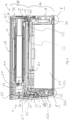
- Figure 8 shows a longitudinal cross-sectional view of the apparatus 10.
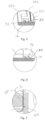
- Figures 9 and 10 show detailed inset views of two regions of the apparatus 10 shown in Figure 8 .
- the divider wall 66 is shown arranged between the chassis 16 of the apparatus 10.
- the divider wall 66 along a first edge is received in a recess 16' in the chassis 16 of the apparatus 10 in a tongue and groove arrangement.
- the first edge of the divider wall 66 may be secured within the recess 16' of the chassis 16 by, for example, an adhesive or simply as a force fit or friction fit.
- the divider wall 66 shown has a groove 84 along the second edge of the divider wall 66.
- a seal 76 is arranged in the groove 84 of the divider wall 66.
- the seal 76 abuts the chassis 16 of the apparatus 10.
- the seal 76 and groove 84 arrangement is such that a substantially hermetic seal is formed along the second edge of the divider wall 66.
- the seal 76 is a resilient member.
- the seal 76 may be made of, for example, one or more polymers such as silicone or rubber.
- the seal 76 may be overmoulded with a sealing material, such as for example thermoplastic polyurethane in groove 84.
- FIG. 9 there is shown a detailed inset view of a region of the apparatus 10 shown in Figure 8 .
- the further seal 78 is located in a groove 86 and is overmoulded with a sealing material, such as for example thermoplastic polyurethane, which is compressed between the housing 14 and the chassis 16.
Applications Claiming Priority (3)
| Application Number | Priority Date | Filing Date | Title |
|---|---|---|---|
| US201662336275P | 2016-05-13 | 2016-05-13 | |
| EP17726217.7A EP3456149B1 (fr) | 2016-05-13 | 2017-05-12 | Dispositif agencé pour chauffer une substance à fumer et procédé de formation du dispositif chauffant |
| PCT/EP2017/061518 WO2017194762A1 (fr) | 2016-05-13 | 2017-05-12 | Appareil agencé pour chauffer un matériau à fumer et procédé de formation d'un élément de chauffage |
Related Parent Applications (2)
| Application Number | Title | Priority Date | Filing Date |
|---|---|---|---|
| EP17726217.7A Division EP3456149B1 (fr) | 2016-05-13 | 2017-05-12 | Dispositif agencé pour chauffer une substance à fumer et procédé de formation du dispositif chauffant |
| EP17726217.7A Division-Into EP3456149B1 (fr) | 2016-05-13 | 2017-05-12 | Dispositif agencé pour chauffer une substance à fumer et procédé de formation du dispositif chauffant |
Publications (2)
| Publication Number | Publication Date |
|---|---|
| EP4245177A2 true EP4245177A2 (fr) | 2023-09-20 |
| EP4245177A3 EP4245177A3 (fr) | 2024-05-15 |
Family
ID=58794043
Family Applications (2)
| Application Number | Title | Priority Date | Filing Date |
|---|---|---|---|
| EP17726217.7A Active EP3456149B1 (fr) | 2016-05-13 | 2017-05-12 | Dispositif agencé pour chauffer une substance à fumer et procédé de formation du dispositif chauffant |
| EP23182510.0A Pending EP4245177A3 (fr) | 2016-05-13 | 2017-05-12 | Dispositif agencé pour chauffer une substance à fumer et procédé de formation du dispositif chauffant |
Family Applications Before (1)
| Application Number | Title | Priority Date | Filing Date |
|---|---|---|---|
| EP17726217.7A Active EP3456149B1 (fr) | 2016-05-13 | 2017-05-12 | Dispositif agencé pour chauffer une substance à fumer et procédé de formation du dispositif chauffant |
Country Status (11)
| Country | Link |
|---|---|
| US (2) | US11438972B2 (fr) |
| EP (2) | EP3456149B1 (fr) |
| JP (4) | JP6833156B2 (fr) |
| CN (2) | CN114652019A (fr) |
| ES (1) | ES2953537T3 (fr) |
| HU (1) | HUE063356T2 (fr) |
| LT (1) | LT3456149T (fr) |
| PL (1) | PL3456149T3 (fr) |
| PT (1) | PT3456149T (fr) |
| RU (2) | RU2709485C1 (fr) |
| WO (1) | WO2017194762A1 (fr) |
Families Citing this family (32)
| Publication number | Priority date | Publication date | Assignee | Title |
|---|---|---|---|---|
| GB201207039D0 (en) * | 2012-04-23 | 2012-06-06 | British American Tobacco Co | Heating smokeable material |
| GB201423315D0 (en) | 2014-12-29 | 2015-02-11 | British American Tobacco Co | Apparatus for heating smokable material |
| AU2016282378B2 (en) | 2015-06-26 | 2018-10-04 | Nicoventures Trading Limited | Apparatus for heating smokable material |
| USD843052S1 (en) | 2015-09-21 | 2019-03-12 | British American Tobacco (Investments) Limited | Aerosol generator |
| TW201742555A (zh) | 2016-05-13 | 2017-12-16 | 英美煙草(投資)有限公司 | 用以加熱可吸菸材料之裝置(二) |
| TW201742556A (zh) | 2016-05-13 | 2017-12-16 | British American Tobacco Investments Ltd | 用以加熱可吸菸材料之裝置(一) |
| GB201612945D0 (en) | 2016-07-26 | 2016-09-07 | British American Tobacco Investments Ltd | Method of generating aerosol |
| TW201932031A (zh) * | 2017-12-29 | 2019-08-16 | 瑞士商傑太日煙國際股份有限公司 | 吸菸裝置 |
| US20190274354A1 (en) | 2018-03-09 | 2019-09-12 | Rai Strategic Holdings, Inc. | Electronically heated heat-not-burn smoking article |
| USD924472S1 (en) | 2018-10-15 | 2021-07-06 | Nicoventures Trading Limited | Aerosol generator |
| USD928393S1 (en) | 2018-10-15 | 2021-08-17 | Nicoventures Trading Limited | Aerosol generator |
| CN109512029A (zh) * | 2018-11-09 | 2019-03-26 | 深圳市麦格米特控制技术有限公司 | 一种电子烟 |
| EP4360479A1 (fr) * | 2019-03-11 | 2024-05-01 | Nicoventures Trading Limited | Dispositif de fourniture d'aérosol |
| USD953613S1 (en) | 2019-03-13 | 2022-05-31 | Nicoventures Trading Limited | Aerosol generator |
| EP3711586A1 (fr) * | 2019-03-22 | 2020-09-23 | Nerudia Limited | Bouchon pour un dispositif de substitution du tabac |
| GB201904748D0 (en) * | 2019-04-04 | 2019-05-22 | Nicoventures Trading Ltd | Apparatus for aerosol generating device |
| GB201907702D0 (en) * | 2019-05-30 | 2019-07-17 | Nicoventures Trading Ltd | Aerosol generation |
| GB201908194D0 (en) * | 2019-06-07 | 2019-07-24 | Nicoventures Trading Ltd | Aerosol provision device |
| WO2020248103A1 (fr) * | 2019-06-10 | 2020-12-17 | Nicoventures Trading Limited | Dispositif de fourniture d'aérosol |
| USD1002922S1 (en) | 2019-07-30 | 2023-10-24 | Nicoventures Trading Limited | Circular interface for aerosol generator |
| US20230337747A1 (en) | 2019-12-23 | 2023-10-26 | Philip Morris Products S.A. | Aerosol-generating system having a ventilation chamber |
| USD926367S1 (en) | 2020-01-30 | 2021-07-27 | Nicoventures Trading Limited | Accessory for aerosol generator |
| KR102455535B1 (ko) * | 2020-06-16 | 2022-10-17 | 주식회사 케이티앤지 | 에어로졸 생성 장치 및 그 동작 방법 |
| CN213344346U (zh) * | 2020-07-14 | 2021-06-04 | 深圳市合元科技有限公司 | 气雾生成装置 |
| JP1714440S (ja) | 2020-10-30 | 2022-05-10 | 喫煙用エアロゾル発生器 | |
| JP1714441S (ja) | 2020-10-30 | 2022-05-10 | 喫煙用エアロゾル発生器 | |
| USD990765S1 (en) | 2020-10-30 | 2023-06-27 | Nicoventures Trading Limited | Aerosol generator |
| JP1714442S (ja) | 2020-10-30 | 2022-05-10 | 喫煙用エアロゾル発生器 | |
| JP1715888S (ja) | 2020-10-30 | 2022-05-25 | 喫煙用エアロゾル発生器 | |
| JP1714443S (ja) | 2020-10-30 | 2022-05-10 | 喫煙用エアロゾル発生器 | |
| USD989384S1 (en) | 2021-04-30 | 2023-06-13 | Nicoventures Trading Limited | Aerosol generator |
| US20230189404A1 (en) * | 2021-12-14 | 2023-06-15 | Inno-It Co., Ltd. | Surface Heating Heater Pipe and Aerosol Generating Device Including the Same |
Family Cites Families (64)
| Publication number | Priority date | Publication date | Assignee | Title |
|---|---|---|---|---|
| US3599646A (en) * | 1969-04-30 | 1971-08-17 | American Filtrona Corp | Cigarette filter |
| JPS5426741B2 (fr) * | 1974-02-21 | 1979-09-05 | ||
| US4253473A (en) | 1979-07-13 | 1981-03-03 | International Flavors & Fragrances Inc. | Process for augmenting or enhancing the aroma or taste of smoking tobacco or a smoking tobacco article by adding thereto a suspended flavoring composition |
| US4955399A (en) * | 1988-11-30 | 1990-09-11 | R. J. Reynolds Tobacco Company | Smoking article |
| DK0503767T3 (da) * | 1991-03-11 | 1995-09-11 | Philip Morris Prod | Duft/smag-dannende artikel |
| US5665262A (en) | 1991-03-11 | 1997-09-09 | Philip Morris Incorporated | Tubular heater for use in an electrical smoking article |
| CR4906A (es) | 1993-09-10 | 1994-09-09 | Philip Morris Prod | Sistema electrico de fumar para distribuir sabores y metodopara su fabricacion |
| GB9609177D0 (en) | 1996-05-02 | 1996-07-03 | Ontario Inc 1149235 | Hand-held smoker's device for sidestream smoke control |
| EP0857431B1 (fr) * | 1996-06-17 | 2003-03-12 | Japan Tobacco Inc. | Accessoire de parfumeur d'ambiance et parfumeur d'ambiance correspondant |
| US5954979A (en) | 1997-10-16 | 1999-09-21 | Philip Morris Incorporated | Heater fixture of an electrical smoking system |
| DE19854005C2 (de) * | 1998-11-12 | 2001-05-17 | Reemtsma H F & Ph | System zur Bereitstellung eines inhalierbaren Aerosols |
| PT1265504E (pt) | 2000-03-23 | 2009-09-04 | Pmpi Llc | Sistema eléctrico para fumar e método |
| US6615840B1 (en) * | 2002-02-15 | 2003-09-09 | Philip Morris Incorporated | Electrical smoking system and method |
| GB0328644D0 (en) | 2003-12-11 | 2004-01-14 | Souza Cruz Sa | Smoking article |
| US9675109B2 (en) | 2005-07-19 | 2017-06-13 | J. T. International Sa | Method and system for vaporization of a substance |
| US20070074734A1 (en) | 2005-09-30 | 2007-04-05 | Philip Morris Usa Inc. | Smokeless cigarette system |
| US7810507B2 (en) | 2006-02-10 | 2010-10-12 | R. J. Reynolds Tobacco Company | Smokeless tobacco composition |
| US7726320B2 (en) | 2006-10-18 | 2010-06-01 | R. J. Reynolds Tobacco Company | Tobacco-containing smoking article |
| US20080302376A1 (en) | 2007-06-08 | 2008-12-11 | Philip Morris Usa Inc. | Smoking article with controlled flavor release |
| TW201023769A (en) * | 2008-10-23 | 2010-07-01 | Japan Tobacco Inc | Non-burning type flavor inhalation article |
| US8262550B2 (en) | 2009-03-19 | 2012-09-11 | R. J. Reynolds Tobacco Company | Apparatus for inserting objects into a filter component of a smoking article |
| EP2253233A1 (fr) | 2009-05-21 | 2010-11-24 | Philip Morris Products S.A. | Système de fumage chauffé électriquement |
| EP2316286A1 (fr) * | 2009-10-29 | 2011-05-04 | Philip Morris Products S.A. | Système de fumage chauffé électriquement doté d'un chauffage amélioré |
| CN101843368A (zh) | 2010-04-02 | 2010-09-29 | 陈志平 | 电子雾化吸入器的吸嘴 |
| RU110608U1 (ru) * | 2011-08-12 | 2011-11-27 | Сергей Павлович Кузьмин | Электронная сигарета |
| WO2013034455A1 (fr) | 2011-09-06 | 2013-03-14 | British American Tobacco (Investments) Limited | Isolation |
| RU2606326C2 (ru) | 2011-09-06 | 2017-01-10 | Бритиш Америкэн Тобэкко (Инвестментс) Лимитед | Нагревание курительного материала |
| UA113744C2 (xx) * | 2011-12-08 | 2017-03-10 | Пристрій для утворення аерозолю з внутрішнім нагрівачем | |
| US9282772B2 (en) | 2012-01-31 | 2016-03-15 | Altria Client Services Llc | Electronic vaping device |
| US20130255702A1 (en) | 2012-03-28 | 2013-10-03 | R.J. Reynolds Tobacco Company | Smoking article incorporating a conductive substrate |
| US9687025B2 (en) * | 2012-09-10 | 2017-06-27 | Healthier Choices Managment Corp. | Electronic pipe |
| WO2014047954A1 (fr) | 2012-09-29 | 2014-04-03 | Liu Shuigen | Dispositif électronique pour fumeur |
| CN104994757B (zh) | 2013-03-15 | 2018-05-18 | 菲利普莫里斯生产公司 | 利用差温加热的气雾生成系统 |
| WO2014166079A1 (fr) | 2013-04-10 | 2014-10-16 | 吉瑞高新科技股份有限公司 | Cigarette électronique incorporée dans une tige d'alimentation électrique |
| SG11201508686UA (en) | 2013-05-21 | 2015-11-27 | Philip Morris Products Sa | Electrically heated aerosol delivery system |
| CN203662020U (zh) | 2013-11-27 | 2014-06-25 | 石世波 | 具有玻璃管雾化座的电子烟雾化器 |
| FI3491948T4 (fi) | 2013-12-23 | 2024-05-06 | Juul Labs International Inc | Höyrystyslaitejärjestelmiä |
| WO2015097187A1 (fr) | 2013-12-24 | 2015-07-02 | Philip Morris Products S.A. | Matière contenant un agent de saveur |
| CN203913377U (zh) | 2014-01-27 | 2014-11-05 | 深圳市施美乐科技有限公司 | 一种一体式一次性电子烟 |
| US9839238B2 (en) | 2014-02-28 | 2017-12-12 | Rai Strategic Holdings, Inc. | Control body for an electronic smoking article |
| CN203828069U (zh) | 2014-03-06 | 2014-09-17 | 刘秋明 | 一种电子烟 |
| GB201407642D0 (en) * | 2014-04-30 | 2014-06-11 | British American Tobacco Co | Aerosol-cooling element and arrangements for apparatus for heating a smokable material |
| CN203952426U (zh) | 2014-05-16 | 2014-11-26 | 申敏良 | 存储烟雾的电子烟雾化器 |
| US9955726B2 (en) | 2014-05-23 | 2018-05-01 | Rai Strategic Holdings, Inc. | Sealed cartridge for an aerosol delivery device and related assembly method |
| US10058123B2 (en) * | 2014-07-11 | 2018-08-28 | R. J. Reynolds Tobacco Company | Heater for an aerosol delivery device and methods of formation thereof |
| CN104095293B (zh) | 2014-07-28 | 2016-08-24 | 川渝中烟工业有限责任公司 | 用于加热不燃烧卷烟的电磁加热型抽吸装置 |
| US9451792B1 (en) | 2014-09-05 | 2016-09-27 | Atmos Nation, LLC | Systems and methods for vaporizing assembly |
| KR101736445B1 (ko) | 2014-09-15 | 2017-05-31 | 주식회사 제이에프티 | 전자담배 |
| CN105795503A (zh) | 2014-12-31 | 2016-07-27 | 普瑞斯生物科技(湖南)有限公司 | 一种中药保健型含橘红提取物的电子烟烟液 |
| US9814271B2 (en) | 2015-01-13 | 2017-11-14 | Haiden Goggin | Multiple chamber vaporizer |
| CN204499486U (zh) | 2015-04-01 | 2015-07-29 | 深圳市欧比斯科技有限公司 | 电子烟雾化器 |
| AU2016282378B2 (en) | 2015-06-26 | 2018-10-04 | Nicoventures Trading Limited | Apparatus for heating smokable material |
| CN104957779B (zh) | 2015-07-23 | 2017-11-14 | 云南中烟工业有限责任公司 | 一种径向分布式多温区电子香烟 |
| US10492528B2 (en) | 2015-08-11 | 2019-12-03 | Altria Client Services Llc | Power supply section configuration for an electronic vaping device and electronic vaping device |
| USD843052S1 (en) | 2015-09-21 | 2019-03-12 | British American Tobacco (Investments) Limited | Aerosol generator |
| CN205337599U (zh) * | 2015-10-22 | 2016-06-29 | 深圳麦克韦尔股份有限公司 | 电子烟及其雾化组件和雾化元件 |
| CN105559151B (zh) | 2016-03-21 | 2019-05-24 | 湖南中烟工业有限责任公司 | 一种超声波雾化器及电子烟 |
| GB201605103D0 (en) | 2016-03-24 | 2016-05-11 | Nicoventures Holdings Ltd | Vapour provision device |
| GB201605100D0 (en) | 2016-03-24 | 2016-05-11 | Nicoventures Holdings Ltd | Vapour provision system |
| GB201607475D0 (en) | 2016-04-29 | 2016-06-15 | British American Tobacco Co | Article for generating an inhalable medium and method of heating a smokable material |
| TW201742554A (zh) | 2016-05-13 | 2017-12-16 | 英美煙草(投資)有限公司 | 用於容收可吸菸材料之裝置 |
| GB201608943D0 (en) | 2016-05-20 | 2016-07-06 | British American Tobacco Co | Capsule for tobacco industry product |
| GB201907702D0 (en) * | 2019-05-30 | 2019-07-17 | Nicoventures Trading Ltd | Aerosol generation |
| GB201917469D0 (en) * | 2019-11-29 | 2020-01-15 | Nicoventures Trading Ltd | Aerosol generation |
-
2017
- 2017-05-12 PT PT177262177T patent/PT3456149T/pt unknown
- 2017-05-12 WO PCT/EP2017/061518 patent/WO2017194762A1/fr active Search and Examination
- 2017-05-12 RU RU2018139838A patent/RU2709485C1/ru active
- 2017-05-12 CN CN202210491702.9A patent/CN114652019A/zh active Pending
- 2017-05-12 US US16/099,294 patent/US11438972B2/en active Active
- 2017-05-12 RU RU2019140780A patent/RU2728533C2/ru active
- 2017-05-12 EP EP17726217.7A patent/EP3456149B1/fr active Active
- 2017-05-12 ES ES17726217T patent/ES2953537T3/es active Active
- 2017-05-12 EP EP23182510.0A patent/EP4245177A3/fr active Pending
- 2017-05-12 JP JP2018554501A patent/JP6833156B2/ja active Active
- 2017-05-12 CN CN201780028361.9A patent/CN109076649B/zh active Active
- 2017-05-12 HU HUE17726217A patent/HUE063356T2/hu unknown
- 2017-05-12 PL PL17726217.7T patent/PL3456149T3/pl unknown
- 2017-05-12 LT LTEPPCT/EP2017/061518T patent/LT3456149T/lt unknown
-
2020
- 2020-11-05 JP JP2020185086A patent/JP7102486B2/ja active Active
-
2022
- 2022-07-06 JP JP2022108981A patent/JP7176825B2/ja active Active
- 2022-07-18 US US17/813,195 patent/US20220369427A1/en active Pending
- 2022-11-08 JP JP2022178840A patent/JP2023022052A/ja active Pending
Also Published As
| Publication number | Publication date |
|---|---|
| WO2017194762A1 (fr) | 2017-11-16 |
| JP2021045132A (ja) | 2021-03-25 |
| US20190208815A1 (en) | 2019-07-11 |
| CN114652019A (zh) | 2022-06-24 |
| RU2019140780A (ru) | 2020-01-27 |
| RU2709485C1 (ru) | 2019-12-18 |
| JP2022133404A (ja) | 2022-09-13 |
| US11438972B2 (en) | 2022-09-06 |
| EP4245177A3 (fr) | 2024-05-15 |
| HUE063356T2 (hu) | 2024-01-28 |
| JP2019518429A (ja) | 2019-07-04 |
| ES2953537T3 (es) | 2023-11-14 |
| CN109076649B (zh) | 2022-06-28 |
| JP7176825B2 (ja) | 2022-11-22 |
| PL3456149T3 (pl) | 2023-10-30 |
| JP2023022052A (ja) | 2023-02-14 |
| RU2019140780A3 (fr) | 2020-06-02 |
| LT3456149T (lt) | 2023-09-11 |
| JP7102486B2 (ja) | 2022-07-19 |
| US20220369427A1 (en) | 2022-11-17 |
| EP3456149A1 (fr) | 2019-03-20 |
| EP3456149B1 (fr) | 2023-08-02 |
| CN109076649A (zh) | 2018-12-21 |
| RU2728533C2 (ru) | 2020-07-30 |
| PT3456149T (pt) | 2023-08-21 |
| JP6833156B2 (ja) | 2021-02-24 |
Similar Documents
| Publication | Publication Date | Title |
|---|---|---|
| US20220369427A1 (en) | Apparatus arranged to heat smokable material and method of forming a heater | |
| US20210368866A1 (en) | Apparatus for receiving smokable material | |
| US11700883B2 (en) | Apparatus for heating smokable material with a hollow tube located in a chamber at an end distal insertion opening |
Legal Events
| Date | Code | Title | Description |
|---|---|---|---|
| PUAI | Public reference made under article 153(3) epc to a published international application that has entered the european phase |
Free format text: ORIGINAL CODE: 0009012 |
|
| STAA | Information on the status of an ep patent application or granted ep patent |
Free format text: STATUS: THE APPLICATION HAS BEEN PUBLISHED |
|
| AC | Divisional application: reference to earlier application |
Ref document number: 3456149 Country of ref document: EP Kind code of ref document: P |
|
| AK | Designated contracting states |
Kind code of ref document: A2 Designated state(s): AL AT BE BG CH CY CZ DE DK EE ES FI FR GB GR HR HU IE IS IT LI LT LU LV MC MK MT NL NO PL PT RO RS SE SI SK SM TR |
|
| REG | Reference to a national code |
Ref country code: DE Ref legal event code: R079 Free format text: PREVIOUS MAIN CLASS: A24F0040700000 Ipc: H05B0003460000 |
|
| PUAL | Search report despatched |
Free format text: ORIGINAL CODE: 0009013 |