EP4244871B1 - Magnetspiegelmaschine - Google Patents
Magnetspiegelmaschine Download PDFInfo
- Publication number
- EP4244871B1 EP4244871B1 EP21810604.5A EP21810604A EP4244871B1 EP 4244871 B1 EP4244871 B1 EP 4244871B1 EP 21810604 A EP21810604 A EP 21810604A EP 4244871 B1 EP4244871 B1 EP 4244871B1
- Authority
- EP
- European Patent Office
- Prior art keywords
- mirror
- area
- magnet system
- magnetic
- plasma
- Prior art date
- Legal status (The legal status is an assumption and is not a legal conclusion. Google has not performed a legal analysis and makes no representation as to the accuracy of the status listed.)
- Active
Links
Images


Classifications
-
- G—PHYSICS
- G21—NUCLEAR PHYSICS; NUCLEAR ENGINEERING
- G21B—FUSION REACTORS
- G21B1/00—Thermonuclear fusion reactors
- G21B1/05—Thermonuclear fusion reactors with magnetic or electric plasma confinement
-
- H—ELECTRICITY
- H05—ELECTRIC TECHNIQUES NOT OTHERWISE PROVIDED FOR
- H05H—PLASMA TECHNIQUE; PRODUCTION OF ACCELERATED ELECTRICALLY-CHARGED PARTICLES OR OF NEUTRONS; PRODUCTION OR ACCELERATION OF NEUTRAL MOLECULAR OR ATOMIC BEAMS
- H05H1/00—Generating plasma; Handling plasma
-
- H—ELECTRICITY
- H05—ELECTRIC TECHNIQUES NOT OTHERWISE PROVIDED FOR
- H05H—PLASMA TECHNIQUE; PRODUCTION OF ACCELERATED ELECTRICALLY-CHARGED PARTICLES OR OF NEUTRONS; PRODUCTION OR ACCELERATION OF NEUTRAL MOLECULAR OR ATOMIC BEAMS
- H05H1/00—Generating plasma; Handling plasma
- H05H1/02—Arrangements for confining plasma by electric or magnetic fields; Arrangements for heating plasma
- H05H1/10—Arrangements for confining plasma by electric or magnetic fields; Arrangements for heating plasma using externally-applied magnetic fields only, e.g. Q-machines, Yin-Yang, base-ball
- H05H1/14—Arrangements for confining plasma by electric or magnetic fields; Arrangements for heating plasma using externally-applied magnetic fields only, e.g. Q-machines, Yin-Yang, base-ball wherein the containment vessel is straight and has magnetic mirrors
-
- Y—GENERAL TAGGING OF NEW TECHNOLOGICAL DEVELOPMENTS; GENERAL TAGGING OF CROSS-SECTIONAL TECHNOLOGIES SPANNING OVER SEVERAL SECTIONS OF THE IPC; TECHNICAL SUBJECTS COVERED BY FORMER USPC CROSS-REFERENCE ART COLLECTIONS [XRACs] AND DIGESTS
- Y02—TECHNOLOGIES OR APPLICATIONS FOR MITIGATION OR ADAPTATION AGAINST CLIMATE CHANGE
- Y02E—REDUCTION OF GREENHOUSE GAS [GHG] EMISSIONS, RELATED TO ENERGY GENERATION, TRANSMISSION OR DISTRIBUTION
- Y02E30/00—Energy generation of nuclear origin
- Y02E30/10—Nuclear fusion reactors
Definitions
- the present disclosure relates to a magnetic mirror machine for plasma confinement.
- nuclei For fusion to occur, nuclei must be in the form of a plasma having a temperature in the order of 150 million kelvins. Providing confinement for such a plasma remains a major challenge.
- Plasma confinement involves confining the charged particles of the plasma.
- a well-known design is the magnetic mirror.
- particles follow magnetic field lines, typically running substantially longitudinally through the magnetic mirror machine, and are reflected in areas of increasing magnetic flux density at the respective ends of the device.
- the plasma confinement area of the magnetic mirror machine is at each of its two ends limited by a respective mirror area of increased magnetic flux density relative to a central area of the plasma confinement area.
- Superconductor coils are well-known for being able to carry large electric currents, thereby, due to Ampere's law, being capable of generating large magnetic flux densities.
- Limiting factors in the design and use of a superconductor coil with respect to the maximum achievable usable magnetic flux density as generated by the coil include, firstly, the maximum electric current density possible in the superconductor material before breakdown of its superconducting properties, and, secondly, the maximum magnetic flux density possible in the superconductor material itself before breakdown of its superconducting properties.
- US4252608 relates to a method and apparatus for raising the potential of a magnetic mirror cell by pumping charged particles of the apposite sign of the potential desired out of the mirror cell through excitation, with the pumping being done by an externally imposed field at the bounce frequency of the above charged particles.
- These pumped simple mirror cells then provide end stoppering for a center mirror cell for the tandem mirror plasma confinement apparatus.
- FURTH ET AL "The energy source: Nuclear fusion reactors", APPLIED ENERGY, ELSEVIER SCIENCE PUBLISHERS, vol. 47, no. 2-3, January 1994, pages 147-167, ISSN: 0306-2619, DOI: 10.1016/0306-2619(94)90076-0 relates to the nature of the fusion reaction and the equipment used for the production of energy. There are several types of reactor with promise. These are described, to provide insight into the types of reactor potentially available as the basis for future energy systems.
- a magnetic mirror machine for plasma confinement comprising a plurality of longitudinally disposed superconductor coils arranged for producing an open-field-line plasma confinement area, said plasma confinement area at each of two ends being limited by a respective mirror area of increased magnetic flux density relative to a central area of said plasma confinement area, wherein a superconductor coil of said of plurality of superconductor coils is located adjacent to said mirror area and said superconductor coil has a cross-section, in a plane intersecting a magnetic field line through said mirror area, having an elongate shape in a direction along said magnetic field line, wherein said plurality of superconductor coils comprises a first magnet system comprising a first plurality of concentrically arranged circular-loop superconductor coils, comprising a first superconductor coil arranged to carry a current in a first direction and a second superconductor coil arranged to carry a current in a second direction opposite to said
- cross-section having an elongate shape should be understood as having an extension, in a first major direction of the cross-section, being at least twice, more preferably three times, even more preferably four times, and even more preferably five times an extension in a second major direction of the cross-section.
- An elongate shape should be understood as include, but not being limited to, a rectangular, elliptical, crescent-shaped, and/or tubular-segment-shaped cross-section.
- the first and second major directions may be orthogonal to each other, but the second direction may also be curved, i.e., having a curved shape with respect to the first direction, as would be the case with a tube-shaped cross section.
- a direction along the magnetic field line should be understood as a direction more parallel to the magnetic field line than perpendicular to the magnetic field line.
- the direction along the magnetic field line may be parallel or substantially parallel to the magnetic field line.
- the present inventive concept stems from a realization that the arranging of the superconductor coil with an elongate cross-section in a direction along a magnetic field line in the mirror area may allow for maximizing the maximum magnetic flux density in the mirror areas of the magnetic mirror machine, given the design constraints of a maximum allowable magnetic flux density within the superconductor coil and a maximum coil current density.
- a high magnetic flux density in the mirror areas may allow for a high mirror ratio in the magnetic mirror machine, i.e., a high ratio between the maximum magnetic flux density in a mirror area and the magnetic flux density in a central area of the magnetic mirror machine, which thereby may reduce the size of the loss cone and allow for better confinement of a plasma.
- a high magnetic flux density in the mirror areas may allow for a high total magnetic flux in the magnetic mirror machine.
- a magnetic mirror machines comprising superconductor coils, maximizing the magnetic flux density in the mirror areas, given the design constraints of the super-conducting coils.
- the high magnetic flux density in the mirror areas may allow for a high product of magnetic flux density in and radius in the central area of the magnetic mirror machine.
- a perimeter segment of said cross-sectional area directed towards said mirror area may convex as seen from outside said perimeter segment.
- the perimeter segment may be curved in a same direction as a magnetic field line in the mirror area. This may allow for further maximizing of the maximum magnetic flux density in the mirror areas.
- a perimeter segment of said cross-sectional area directed away from said mirror area may be concave as seen from outside said perimeter segment.
- the perimeter segment may be curved in a same direction as a magnetic field line in the mirror area. This may allow for further maximizing of the maximum magnetic flux density in the mirror areas.
- the perimeter segment of said cross-sectional area directed towards said mirror area runs may run parallel to the perimeter segment of said cross-sectional area directed away from said mirror area. This may allow for further maximizing of the maximum magnetic flux density in the mirror areas.
- the plurality of superconductor coils may be disposed co-axially and longitudinally spaced and each arranged for carrying respective currents in a same direction. This is a particularly beneficial application of the present inventive concept.
- the plurality of superconductor coils may further comprise a third magnet system arranged radially outside said plasma confinement area, said third magnet system comprising at least one superconductor circular-loop coil.
- a fusion reactor comprising the magnetic mirror machine of the first aspect. This aspect may generally present the same features and advantages as the first aspect.
- plasma confinement devices may be based either on open magnetic field lines or closed field lines.
- a closed-field-line configuration may, for example, be realized with a toroidal magnetic field.
- An example of such a device is a tokamak.
- Open-field-line plasma confinement devices may operate by a principle of magnetic mirroring, wherein the charged particles of the plasma are reflected in areas of increasing magnetic flux density at the respective ends of the confinement area.
- open-field-line plasma confinement devices While recognized to be able to provide plasma confinement, open-field-line plasma confinement devices will always have leakage of charge particles with velocity vectors sufficiently aligned with the magnetic field lines. More specifically, the mirror effect will occur for all particles within a range of angles of approach outside a loss cone defined by the helix spiral pitch angle of the charged particle's gyration spin around the magnetic field lines.
- ⁇ cone arccos 1 r mirror .
- the superconductor coils throughout this disclosure may be manufactured and arranged using methods, materials, compounds, and the like, known per se in the art.
- Suitable superconductor materials may include YBCO, Bi2223, 2212, Nb3SN, NbTi and/or MgB2.
- the superconductor coils throughout this disclosure may, for example, be so-called high-temperature superconductor coils.
- a superconductor coil may comprise internal structure.
- superconducting material may be arranged in filaments, strands, cables, ropes, or the like. using methods generally known in the art.
- the cross-section of the coil, as referred to throughout this disclosure, should then be understood as an enclosing envelope of this internal structure.
- the superconductor coils throughout this disclosure may be manufactured and arranged using methods, materials, compounds, and the like, as detailed in D Uglietti: A review of commercial high temperature superconducting materials for large magnets: from wires and tapes to cables and conductors, Supercond. Sci. Technol. 32 (2019) 053001 (29pp), htps://doi.Org/10.1088/1361-6668/ab06a2 .
- the superconductor coils may be cooled using methods generally known per se in the art.
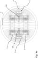
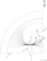
- Fig. 18 is a cross-sectional view of a magnetic mirror machine 2100.
- the magnetic mirror machine 2100 is rotationally symmetric, or at least substantially rotationally symmetric, around a symmetry axis A.
- the magnetic mirror machine 2100 may be used for plasma confinement, and may comprise customary shielding 2102, for example neutron shielding 2102, as known in the art.
- the magnetic mirror machine 2100 may be comprised in a fusion reactor and/or used in a fusion reactor.
- the magnetic mirror machine 2100 comprises a plurality superconductor coils 104, 105, longitudinally-disposed along the symmetry axis A.
- Each superconductor coil 104, 105 may be arranged in a circular loop, as in Fig. 18 , and may be arranged for carrying a direct current, for generating an open-field-line plasma confinement area 2106, as known per se in the art.
- the plasma confinement area 2106 thus extends in a longitudinal direction of the magnetic mirror machine 2100, along the symmetry axis A, through the magnetic mirror machine 2100, with the magnetic field lines 2112 running along the longitudinal direction as well.
- the plurality of superconductor coils 2104, 2105 are disposed co-axially, in the example of Fig. 18 with respect to the symmetry axis A. Further, the superconductor coils are longitudinally spaced with respect to the symmetry axis A. Further, as typical in a magnetic bottle arrangement, each superconductor coil is arranged for carrying respective currents in a same direction, as marked with dots and crosses in Fig. 18 .
- the plasma confinement area 2106 is at each of two ends limited by a respective mirror area 2108 of increased magnetic flux density relative to a central area 2110 of the plasma confinement area 2106, as is evident from the magnetic field line spacing in each mirror area 2108 and the central area 2110, and as known per se in the art.
- a respective superconductor coil 2105 of the plurality of superconductor coils 2105, 2106 is located adjacent to each respective mirror area 2108. Indeed, in the example of Fig. 18 , the respective superconductor coil 2105 is located radially outside the respective mirror area 2108.
- the superconductor coil 2106 has a cross-section, in a plane intersecting a magnetic field line 2112 through said mirror area, thus corresponding to the plane of Fig. 18 , having an elongate shape in a direction along the magnetic field line 2112.
- this may be formulated as the superconductor coil 2106 has having a cross-section elongate in a longitudinal direction with respect to the magnetic mirror machine 2100 and/or the superconductor coil 2106 has having a cross-section elongate in a direction along the symmetry axis A.
- the cross section is rectangular, having a dimension in the direction along the magnetic field line 2112 and/or the longitudinal direction of the magnetic mirror machine 2100 and/or the direction along the symmetry axis A about twice the size of a dimension perpendicular to that direction, i.e., radially in the magnetic mirror machine 2100.
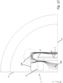
- Fig. 19 shows a further magnetic mirror machine 2200.
- the magnetic mirror machine 2200 has the same features as the magnetic mirror machine 2100 of Fig. 1 , with an exception that each of the superconductor coils 2206 adjacent to each respective mirror area 108 has a tubular-segment-like cross section, i.e., having a general shape of a circular segment as if formed from part of a tube.
- each superconductor coil 2105 is such that a perimeter segment 2307a of the cross-sectional area directed towards the mirror area 2108 is convex as seen from outside the perimeter segment 2307a.
- a perimeter segment 2307b of the cross-sectional area of each superconductor coil 2306 directed away from the mirror area is concave as seen from outside the perimeter segment 2307b.
- the perimeter segment 2307a of the cross-sectional area directed towards the mirror area 2108 runs parallel to the perimeter segment 2307b of the cross-sectional area directed away from the mirror area.
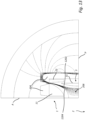
- Fig. 20 shows a further magnetic mirror machine 2300, not according to the present inventive concept, but presented as an example useful for understanding the present inventive concept.
- the magnetic mirror machine 2300 has the same features as the magnetic mirror machine 2100 of Fig. 1 , with an exception that each of the superconductor coils 2406 adjacent to each respective mirror area 2108 has a circular cross section, i.e., not being elongate.
- Magnetic field simulations were performed to evaluate the designs of the magnetic mirror machine 2100 of Fig. 18 , the magnetic mirror machine 2200 of Fig. 19 , the magnetic mirror machine 2300 of Fig. 20 .
- Table 1 shows results of the simulations, wherein: • B coil is the maximum magnetic flux density within each coil 2105, adjacent to the mirror area 2108, • B mirror is the maximum magnetic flux in the mirror area 2108, • B central, outer is the magnetic flux density at the symmetry plane P, at an radially outermost edge of the central area 110, • B central, avg is the magnetic flux density at the symmetry plane P, radially averaged through the central area 110, and • R is the inner radius of the magnetic mirror machine 2100, 2200, 2400, the final line of Table 1 thus showing the product of B central, avg and R.
- Table 1 Machine 2300 ( Fig. 20 ) 2100 ( Fig. 18 ) 2200 ( Fig.
- the simulations were performed using a wall 2102 thickness of 700 mm, an initial magnetic mirror machine inner radius R at the symmetry plane P of 3 300 mm, and a distance between the symmetry plane P and the coils 2105 of 5 000 mm.
- the simulations were performed assuming a constant current density within each superconductor coil and with a constraint that the maximum magnetic flux density within each coil 2105 adjacent to the mirror area 2108 must not exceed approximately 23 T, being a typical value for a breakdown magnetic flux density for the respective superconductor coil.
- each magnetic mirror machine was varied so that the product B central, avg x R of the average magnetic flux density B central, avg at the symmetry plane P and the inner radius R of the magnetic mirror machine, the latter thus roughly corresponding to the radius of the plasma confinement area 1206 at the symmetry plane P, was fixed at 6.0 T m.
- B coil is in each case is close to 23 T. It should be noted that due to the linear nature of magnetic fields, the present results may be readily be scaled to other coil maximum magnetic flux densities than 23 T, for which the results are equally valid.
- the elongate coil cross section in the magnetic mirror machine 2200 allows for a higher magnetic flux density B mirror in the mirror area, given the constraint of not exceeding a magnetic flux density of approximately 23 T in the coil, as compared to the circular non-elongate coil 2105 of the magnetic mirror machine 2300 of Fig. 20 .
- the tubular-segment cross section of the coil 2105 of the magnetic mirror machine 2400 of Fig. 20 allows for a yet higher B mirror , as compared to Figs 19 and 18 .
- the magnetic flux density B central, outer of the central area remains roughly constant in each magnetic mirror machine.
- the increased B mirror in Figs 18 and 19 as compared to Fig. 20 may translate into an increased mirror ratio B mirror / B central,outer of the magnetic mirror machine, given the fixed product B central,avg x R.
- the present inventive concept is refers to a magnetic mirror machine wherein the plurality of superconductor coils comprises a first magnet system comprising a first plurality of concentrically arranged circular-loop superconductor coils, comprising a first superconductor coil arranged to carry a current in a first direction; and a second superconductor coil arranged to carry a current in a second direction opposite to the first direction; and a second magnet system comprising a second plurality of concentrically arranged circular-loop coils, arranged with mirror symmetry with respect to the first magnet system relative to a symmetry plane located between the first magnet system and the second magnet system, the concept of and advantages of which being discussed in detail elsewhere in this disclosure.
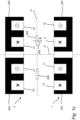
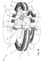
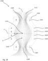
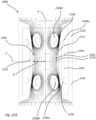
- Figs 21A and 21B show such a magnetic mirror machine 3100, wherein Fig. 21A is a cross-sectional view of the magnetic mirror machine 2200, and Fig. 21B is a close-up of a single quadrant of Fig. 21A , which due to rotational and mirror symmetry is representative of all four quadrants of the cross section shown in Fig. 21A .
- the magnetic mirror machine 3100 is rotationally symmetric, or at least substantially rotationally symmetric, around a symmetry axis A.
- the magnetic mirror machine 3100 may be used for plasma confinement, and may comprise customary shielding 2102, for example neutron shielding 2102, as known in the art.
- the magnetic mirror machine 2100 may be comprised in a fusion reactor and/or used in a fusion reactor.
- the magnetic mirror machine 3100 comprises a plurality of superconductor coils 2204, 2206a, 2206b, longitudinally-disposed along the symmetry axis A.
- Each superconductor coil 2204, 2206a, 2206b may be arranged in a circular loop, as in Figs 21A / 21B , and may be arranged for each carrying a direct current arranged for producing an open-field-line plasma confinement area 2106.
- the plasma confinement area 2106 thus extends in a longitudinal direction, along the symmetry axis A, through the magnetic mirror machine 3100, with the magnetic field lines 2112 in the plasma confinement area 2106 running in the longitudinal direction as well.
- superconductor coils 2206a and 2206b located above the symmetry plane P constitute a first magnet system, wherein the coil 2206a is arranged to carry a direct current in a first direction and the coil 2206b is arranged to carry a direct current in a second, opposite, direction, as indicated with dots and crosses in Fig. 21B .
- the superconductor coils 2206a and 2206b located below the symmetry plane P constitute a second magnet system, arranged with mirror symmetry with respect to the first magnet system relative to the symmetry plane P, which thus is located between the first magnet system and the second magnet system.
- annular confinement area 2106 may be created, as detailed elsewhere in this disclosure.
- a third magnet system comprising at least one superconductor coil, typically a plurality of superconductor coils, and in the example of Figs 21A and 21B two superconductor coils 2104, may be arranged radially outside the plasma confinement area 2106.
- the plasma confinement area 2106 is at each of two ends limited by a respective mirror area 2108 of increased magnetic flux density relative to a central area 2110 of the plasma confinement area 2106, as is evident from the magnetic field line spacing in each mirror area 2108 and the central area 2110.
- the superconductor coils 2206a, 2206b of the first magnet system and of the second magnet system are located adjacent to the respective mirror area 2108.
- the superconductor coils 2206a are located radially outside the respective mirror area 2108 and the superconductor coils 2206b are located radially inside the respective mirror area 2206a.
- each superconductor coil 2206a, 2206b of the first magnet system and of the second magnet system has a cross-section, in a plane intersecting a magnetic field line 2112 through said mirror area, thus corresponding to the plane of Figs 21A / 21B , having an elongate shape in a direction along the magnetic field line 2112.
- the cross section is crescent shaped, having a dimension in the direction along the magnetic field line 2112 about twice the size of a dimension perpendicular to that direction.
- each of the superconductor coils 2206a, 2206b adjacent to each respective mirror area 2108 has a crescent-shaped cross section.
- the cross section of each superconductor coil is such that a perimeter segment 2207a of the cross-sectional area directed towards the mirror area 2108 is convex as seen from outside the perimeter segment 2207a.
- this may be formulated as the superconductor coil 2206a, 2206b having a cross-section elongate in a longitudinal direction with respect to the magnetic mirror machine 3100 and/or the superconductor coil 2206a, 2206b having a cross-section elongate in a direction along the symmetry axis A.
- the perimeter segments 2207b directed away from the mirror area 2108 may be flat.
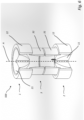
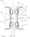
- Figs 22A and 22B show a further magnetic mirror machine 3200.
- the magnetic mirror machine 3200 has the same features as the magnetic mirror machine 3100 of Fig. 1 , with an exception that each of the superconductor coils 2206 adjacent to each respective mirror area 108 has a tubular-segment-like cross section, i.e., having a general shape of a circular segment as if formed from part of a tube. Naturally, other curved cross sections are equally possible, not necessarily following a circular segment path.
- each superconductor coil is such that a perimeter segment 2207a of the cross-sectional area directed towards the mirror area 2108 is convex as seen from outside the perimeter segment 2207a.
- a perimeter segment 2207b of the cross-sectional area of each superconductor coil 2306 directed away from the mirror area is concave as seen from outside the perimeter segment 2207b.
- the perimeter segment 2207a of the cross-sectional area directed towards the mirror area 2108 runs parallel to the perimeter segment 2207b of the cross-sectional area directed away from the mirror area.
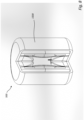
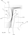
- Figs. 23A and 23B shows a further magnetic mirror machine 2400, not according to the present inventive concept, but presented as an example useful for understanding the present inventive concept.
- the magnetic mirror machine 4200 has the same features as the magnetic mirror machine 2100 of Figs 21A and 21B , with an exception that each of the superconductor coils 2206a, 2206b adjacent to each respective mirror area 2108 has a circular cross section, i.e., the cross section being non-elongate.
- Magnetic field simulations were performed to evaluate the designs of the magnetic mirror machine 3100 of Figs 21A and 21B , the magnetic mirror machine 3200 of Figs 22A and 22B , and the magnetic mirror machine 3300 of Figs 23A and 23B .
- the simulations were performed using a wall 2102 thickness of 700 mm, a magnetic mirror machine inner radius R at the symmetry plane P of 3 300 mm, and a distance between the symmetry plane P and the coils 2206a, 2206b of 5 000 mm.
- the simulations were performed assuming a constant current density within the superconductor coil and with a constraint that the maximum magnetic flux density within each coil 2105 adjacent to the mirror area 2108 must not exceed approximately 23 T, being a typical value for a breakdown magnetic flux density for the respective superconductor coil.
- each magnetic mirror machine was varied so that the ratio B coil / B mirror was maximized, being equivalent to maximizing B mirror due to the constant B coil .
- the elongate crescent-shaped coil cross sections in the magnetic mirror machine 3100 allow for a higher magnetic flux density B mirror in the mirror area, given the constraint of not exceeding a magnetic flux density of approximately 23 T in the coil, as compared to the circular non-elongate coil 2206a, 2206b of the magnetic mirror machine 3300 of Figs 23A / 23B .
- the tubular-segment cross section of the coils 2206a, 2206b of the magnetic mirror machine 3200 of Figs 22A and 22B allows for a yet higher B mirror , as compared to Figs 23A / 23B and 21A / 21B .
- the magnetic flux density B central,outer of the central area remains around 7-8 T, while the elongate and tubular segment cross-sections allow for a considerably increased product B central,avg R.
- the remainder of this disclosure relates to a plasma confinement device and to a method for plasma confinement.
- nuclei For fusion to occur, nuclei must be in the form of a plasma having a temperature in the order of 150 million kelvins. Providing confinement for such a plasma remains a major challenge.
- Plasma confinement involves confining the charged particles of the plasma. Further, various properties beneficial to the stability of the confined plasma may be desirable.
- a well-known design is the magnetic mirror. Therein, particles follow magnetic field lines and are reflected in areas of increasing magnetic flux density at the respective ends of the device. While capable of plasma confinement, as has been demonstrated experimentally, it is associated with various plasma instability problems. To solve these problems, various convoluted non-rotationally symmetric geometries have been proposed in the prior art, such as the "Minimum B” design, resembling a tennis ball, or the "Biconic Cusp".
- the tokamak uses a toroidal, i.e., donut-shaped, field for confinement.
- the tokamak too, is associated with various plasma stability problems, such as charge separation.
- a plasma confinement device comprising a first magnet system, comprising a first plurality of concentrically arranged circular-loop coils, comprising a first coil arranged to carry a current in a first direction, and a second coil arranged to carry a current in a second direction opposite to the first direction; and a second magnet system comprising a second plurality of concentrically arranged circular-loop coils, arranged with mirror symmetry with respect to the first magnet system relative to a symmetry plane located between the first magnet system and the second magnet system, creating an annular plasma confinement area at the symmetry plane with a magnetic field normal to the symmetry plane at the symmetry plane.
- annular plasma confinement area should be understood a rotationally symmetric region in which the charged particles of the plasma are confined, including cases having, for example, a donut-like or disc-like topology.
- the resulting magnetic field configuration may confine charged particles using static axial and radial fields in an open-field-line magnetic mirror configuration.
- the arrangement with the first coil being arranged to carry a current in a first direction and the second coil being arranged to carry a current in an opposite, second, direction, in each of the first magnet system and the second magnet system allows for the creation of a region of high magnetic flux density between the first coil and the second coil, while maintaining a relatively lower flux density near the symmetry plane. Compared to a conventional magnetic mirror arrangement, this allows for an increased mirror ratio, thereby reducing the size of the loss cone and allowing for better confinement of the plasma.
- a fusion reactor when confining a plasma, the charge separation effects may be avoided, where no induced plasma current may be needed for stability of the plasma.
- the resulting quasi-static plasma i.e., without a global plasma current, one may in turn avoid magnetohydrodynamic instabilities.
- a fusion reactor may be allowed to run in a continuous (steady) state without current ramping.
- the resulting magnetic field configuration may allow for an uncomplicated way of heating the plasma.
- the first plurality of concentrically arranged coils may, for example, be identically designed to the second plurality of concentrically arranged coils. This is a particularly simple way of achieving the desired magnetic field configuration.
- the device may further comprise a third magnet system arranged radially outside the plasma confinement area, the third magnet system comprising at least one circular-loop coil.
- the arrangement with a third magnet system may allow for arranging a concave magnetic field in the whole plasma confinement area, which may be beneficial for the stability of the confined plasma.
- a rotationally symmetric open-field-line plasma confinement device may be provided that has a high mirror ratio and has properties beneficial for plasma stability.
- the third magnet system may allow controlling a confined plasma by current adjustment in the circular-loop coil of the third magnet system.
- the third magnet system may comprise a first coil arranged on a same side of the symmetry plane at the first magnet system and a second coil arranged on an opposite side of the symmetry plane, wherein the second coil is arranged with mirror symmetry relative to the first coil.
- the first plurality of concentrically arranged coils in the first magnet system and the second plurality of concentrically arranged coils in the second magnet system may each be embedded in respective ferromagnetic structures. This increases the magnetic flux through the relatively higher permeability of the ferromagnetic material, leading to a stronger magnetic field, and thereby better confinement, for a given coil current.
- a said ferromagnetic structure does not cover at least one coil of a respective said plurality of coils in a direction towards said symmetry plane.
- a said ferromagnetic structure may be ferromagnetic steel.
- the device according to the first aspect may be used for confining a plasma.
- the device according to the first aspect may be used in a fusion reactor.
- a method of plasma confinement comprising, in a first magnet system, comprising a first plurality of concentrically arranged circular-loop coils, a first coil carrying a current in a first direction and a second coil carrying a current in a second direction opposite to the first direction; and a second magnet system comprising a second plurality of concentrically arranged circular-loop coils carrying currents with mirror symmetry with respect to the first magnet system relative to a symmetry plane located between the first magnet system and the second magnet system, creating an annular plasma confinement area at the symmetry plane with a magnetic field normal to the symmetry plane.
- Embodiments and advantages of this second aspect may generally be similar to or the same as those of the first embodiment.
- the method may further comprise controlling a confined plasma by current adjustment in a third magnet system arranged radially outside the plasma confinement area.
- the controlling may comprise changing the radius of the plasma confinement area, which thereby, in turn, may change the radius of the plasma.
- the method may further comprise heating the plasma by inserting an ion beam in an area radially outside the plasma confinement area or radially inside the plasma confinement area and allowing ions from the ion beam to drift into the plasma confinement area.
- a magnetic mirror machine and/or a particle confinement device comprising a first magnet system, comprising a first plurality of concentrically arranged circular-loop coils, comprising a first coil arranged to carry a current in a first direction, and a second coil arranged to carry a current in a second direction opposite to the first direction; and a second magnet system comprising a second plurality of concentrically arranged circular-loop coils, arranged with mirror symmetry with respect to the first magnet system relative to a symmetry plane located between the first magnet system and the second magnet system, creating an annular particle confinement area at the symmetry plane with a magnetic field normal to the symmetry plane at the symmetry plane.
- a method of confining charged particles comprising, in a first magnet system, comprising a first plurality of concentrically arranged circular-loop coils, a first coil carrying a current in a first direction and a second coil carrying a current in a second direction opposite to the first direction; and a second magnet system comprising a second plurality of concentrically arranged circular-loop coils carrying currents with mirror symmetry with respect to the first magnet system relative to a symmetry plane located between the first magnet system and the second magnet system, creating an annular particle confinement area at the symmetry plane with a magnetic field normal to the symmetry plane.
- plasma confinement devices may be based either on open magnetic field lines or closed field lines.
- Closed-field line devices may, for example, have a toroidal magnetic field.
- An example of such a device is a tokamak.
- Closed-field-line devices may potentially confine plasma particles without leakage, as the particles will follow the field lines, but other issues, such as ExB drift due to charge separation and magneto-hydrodynamic (MHD) effects may cause a plasma to escape. Special arrangements need to be made for removing helium ash, such as pulsing the system, disallowing steady-state operation.
- this problem may be addressed by inducing a current in the plasma, where the current will create a poloidal field. This results in the magnetic field twisting along the torus, with poloidal and toroidal fields together making up the twisted magnetic field. This mitigates the E ⁇ B drift but introduces an additional problem in that the plasma only will be confined while the current in the inner magnetic coil is ramping up, i.e. it is not possible to run in steady state.
- the plasma current will result in several instabilities related to magnetohydrodynamic effects, such as Kink instabilities. This may be addressed by various compensation coils around the reactor vessel, but the basic characteristics of the plasma will still be unstable due to the large magnetohydrodynamic effects.
- Open-field-line plasma confinement devices may operate by a principle of magnetic mirroring, wherein the charged particles of the plasma are reflected in areas of increasing magnetic flux density at the respective ends of the confinement area.
- Such machines have the ability of steady-state operation, and may generally have less problems with charge separation, and also allow for easier handling of helium ashes.
- open field-line plasma confinement devices will always have leakage of charge particles with velocity vectors sufficiently aligned with the magnetic field lines. More specifically, the mirror effect will occur for all particles within a range of angles of approach outside a loss cone defined by the helix spiral pitch angle of the charged particle's gyration spin around the magnetic field lines.
- ⁇ cone arccos 1 r mirror .
- a first property, known from literature, of the magnetic field lines of a plasma confinement device, associated with magneto-hydrodynamic stability of the confined plasma, is a concave magnetic field, i.e., a magnetic field having concave magnetic field lines, as seen from outside the plasma confinement area and the confined plasma.
- Figs 1a , 1b , and 1c show a first magnet system 1 and a second magnet system 2 that may be comprised in a plasma confinement device (cf. Figs 5a and 5b ).
- the first magnet system 1 comprises a first plurality of concentrically arranged circular-loop coils arranged around a symmetry axis A, for example, as shown a first, inner coil 11 and a second, outer, coil 12, arranged concentrically to radially outside the inner coil 11.
- the first magnet system 1 comprises a second magnet system 2 comprising a second plurality of circular-loop coils, likewise concentrically arranged around the axis A, but vertically displaced relative to the first magnet system.
- the second magnet system may, for example, as shown, comprise a first, inner coil 21 and a second, outer, coil 22, arranged concentrically to and radially outside the inner coil 21.
- Fig. 1c shows a cross sectional view through the first magnet system 1 and the second magnet system 2 in a cross-sectional plane through the symmetry axis A.
- the coils 21, 22 of the second magnet system 2 are arranged with mirror symmetry with respect to the coils 11, 12 of first magnet system 1 relative to a symmetry plane P, which is at equal distance to each of the first magnet system 1 and to the second magnet system 2.
- the cartesian coordinate system should be understood as having the first two coordinate axes "x, y", “X, Y", “A, B”, or the like, lying in the symmetry plane P and the third coordinate axis "z", “Z”, "C”, or the like, extending in a positive direction upwards (as seen in Figs 1-5 ) from the origin along the symmetry axis A.
- the cylindrical coordinate system should be understood as having a radial direction and coordinate ("R”, “r”, or the like) extending from the origin at the intersection of the symmetry axis A and the symmetry plane P, an azimuth direction and coordinate ("phi”, “Phi”, or the like) measured as a rotational angle around the symmetry axis A, and an axial direction and coordinate ("z”, “Z”, “C” or the like) extending in a positive direction from the origin upwards along the symmetry axis A.
- Positive direction for the azimuth direction is according to the right-hand rule with respect to the positive axial direction.
- the first plurality of concentrically arranged coils 11, 12 of the first magnet system 1 may, as shown, be identically designed to the second plurality of concentrically arranged coils 21, 22 of the second magnet system 2, respecting the mirror symmetry.
- Fig. 1c further shows coil current directions during operation of the first magnet system and the second magnet system as used in a plasma confinement device (cf. Figs 5a and 5b ).
- the current of the inner coil 11 is configured to run in a direction into the cross-sectional plane (marked with a cross) on the right side of Fig. 1c and out of the cross-sectional plane (marked with a dotted circle) in the left side of Fig. 1c , i.e., counter-clockwise a seen from above the first magnet system.
- the current of the outer coil 12 is configured to run in a direction out of the cross-sectional plane (marked with a dotted circle) on the right side of Fig. 1c and into the cross-sectional plane (marked with a cross circle) in the left side of Fig. 1c , i.e., clockwise a seen from above the first magnet system.
- the first plurality of concentrically arranged circular-loop coils comprises a first coil 11 arranged to carry a current in a first direction, and a second coil 12 arranged to carry a current in a second direction opposite to the first direction.
- the current of the inner coil 21 is configured to run in a direction into the cross-sectional plane (marked with a cross) on the right side of Fig. 1c and out of the cross-sectional plane (marked with a dotted circle) in the left side of Fig. 1c , i.e., counter-clockwise a seen from above the first magnet system and the current of the outer coil 22 is configured to run in a direction out of the cross-sectional plane (marked with a dotted circle) on the right side of Fig. 1c and into the cross-sectional plane (marked with a cross circle) in the left side of Fig. 1c , i.e., clockwise a seen from above the first magnet system.
- the currents of the second magnet system 2, with first magnet system 1 and the second magnet system 2 in operation are arranged with mirror symmetry with respect to the first magnet system relative to the symmetry plane P located between the first magnet system 1 and the second magnet system 2.
- the mirror-symmetric configuration of currents in the first magnet system 1 and the second magnet system 2 creates, at the symmetry plane P, a magnetic field normal to the symmetry plane P.
- An annular, typically toroid-shaped, plasma confinement area 206 (cf. Figs 2 , 5a and 5b ), indicated with an approximate dashed ellipse, is formed at the symmetry plane P, as will be explained further in the following.
- a plasma confinement device may comprise two disc-shaped magnet systems 1, 2 facing each other in axial direction, with a space in-between where a plasma may be confined.
- Each magnet system 1, 2 has at least two coils 11, 12, 21, 22 where the current direction and magnitude create a normal magnetic field boundary condition at the symmetry plane P.
- the first plurality of concentrically arranged coils 11, 12 in the first magnet system 1 and the second plurality of concentrically arranged coils 21, 22 in the second magnet system 2 each may be embedded in respective core structures 204, which may be of ferromagnetic material, such as ferromagnetic steel.
- the core structure 204 may be of non-ferromagnetic material, such as non-ferromagnetic steel.
- the respective core structures 204 of the first magnet system 1 and the second magnet system 2 do not cover at least one coil, as shown all coils of the respective plurality of coils in a direction towards the symmetry plane P, but covers the respective coils 11, 12, 21, 22 in all other directions.
- Fig. 9 shows simulated magnetic field lines, of a straight magnetic mirror configuration comprising two coils, viz., a single coil 1600 in each hemisphere.
- the magnetic field displays a region 1602 of relatively low magnetic flux density near the symmetry plane P and a region 1604 of relatively high magnetic flux density near the coil 1600, creating a confinement area 206 for charged particles, based on the principle of magnetic reflection, as explained above.
- the confinement area 206 i.e. from the right in Fig.
- the disclosed magnet system configurations makes the magnetic field normal to the symmetry plane P throughout the symmetry plane P, as is evident by the magnetic field lines crossing the symmetry plane P at right angles.
- Fig. 2 just as Fig. 1c , shows the magnetic field lines in a cross-sectional plane through the axis A. Due to the rotational symmetry of the first magnet system 1 and the second magnet system 2, the magnetic field configuration is also rotationally symmetric, so that to that Fig. 2 is representative for any such cross-sectional plane and therefore for the whole field configuration.
- the magnetic field has no toroidal component, i.e., in a direction pointing into or out of the cross-sectional plane of Fig. 2 , which is the azimuth direction referred to above.
- the magnetic field vectors lie in the cross-sectional plane for any such cross-sectional plane through the axis A. The same applies for the configurations of Figs 9-13 .
- FIG. 2 magnetic field lines resulting from the mirror-symmetric configuration of currents in the first magnet system 1 and the second magnet system 2 discussed above in conjunction with Figs 1a , 1b , and 1c , are shown.
- the resulting magnetic field configuration results in the annular confinement area 206, again represented by approximate dashed ellipses, in which ions of a plasma may be confined.
- the plasma confinement area is radially restricted between an inner radius and an outer radius, as confirmed by simulations.
- Plasma ions confined in the plasma confinement device, in the plasma confinement area 206 at the symmetry plane P will perform a circular gyration motion in that plane due to the magnetic field perpendicular to that plane. As mentioned, no toroidal field is present.
- a confinement device confines plasma with axial (parallel to the axis A) and radial fields.
- Fig, 10 shows another configuration that may be comprised in a plasma confinement device, again, arranged with a first magnet system 1 comprising a first coil 11 arranged to carry a current in a first direction; and a second coil 12 arranged to carry a current in a second direction opposite to the first direction (cf. Fig. 1c ); and a second magnet system (not shown) comprising a first and a second concentrically arranged circular-loop coil (not shown), arranged with mirror symmetry with respect to said first magnet system relative to the symmetry plane P located between the first magnet system 1 and the second magnet system 2.
- a confinement area for charged particles i.e., a plasma confinement area 206, is the symmetry plane P with a magnetic field normal to the symmetry plane at the symmetry plane.
- Figs 3a and 3b show a first magnet system 1, a second magnet system 2, and a third magnet system that may be comprised in a plasma confinement device (cf. Figs 5a and 5b ).
- a plasma confinement device cf. Figs 5a and 5b .
- the magnet systems of Figs 3a , 3b , and Fig. 4 have the same features and characteristics as the first magnet system and the second magnet system described above in conjunction with Figs. 1a , 1b , 1c , and 2 .
- the third magnet system 3 is arranged radially outside, with respect to the axis A, the plasma confinement area 206.
- the third magnet system 3 may, as shown, be located radially outside, with respect to the axis A, the first magnet system 1 and the second magnet system 2.
- the third magnet system 3 comprises at least one circular-loop coil, for example, as shown, a first circular-coil loop coil 31 arranged on the same side of the symmetry plane P as the first magnet system and a second circular-coil loop 32 arranged on the opposite side of the symmetry plane P, wherein the second coil 32 is arranged with mirror symmetry relative to the first coil 31.
- each of the first coil 31 and the second coil 32 has a current configured to run, with the magnet system in operation, in a direction into the cross-sectional plane (marked with a cross) on the left side of Fig. 3b and out of the cross-sectional plane (marked with a dotted circle) on the right side of Fig. 3c, i.e., clockwise as seen from above the first magnet system.
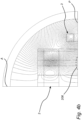
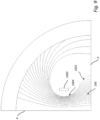
- Figs 4a and 4b Resulting simulated magnetic field lines are shown in Figs 4a and 4b .
- the magnetic field configuration is similar to that of Fig. 2 .
- an annular plasma confinement area 206 is formed, just as described above in conjunction with Figs. 1a , 1b , 1c , and 2 .
- Fig. 4b shows a quadrant of Fig. 4a close up. Due to the symmetry properties of the magnet systems, the magnetic field properties of such a quadrant are sufficient for describing the field configuration as a whole, i.e., due to the mirror symmetry with respect to the symmetry plane P and the rotational symmetry around the axis A.
- Fig. 11 shows yet another configuration that may be comprised in a plasma confinement device.
- a third magnet system 3 is arranged radially outside the plasma confinement area 206.
- the third magnet system comprises a circular-loop coil 31.
- the field configuration displaying a region 1602 of relatively low magnetic flux density near the symmetry plane P and a region 1604 of relatively high magnetic flux density near the coils 11, 12, creating a confinement area 206 for charged particles, based on the principle of magnetic reflection.
- the region 1602 near the symmetry plane displays concave magnetic field lines, as seen from outside the plasma confinement area 206, while the region 1604 displays convex magnetic field lines, again as seen from outside the plasma confinement area 206.
- the region of concave magnetic field lines is larger than with the configuration of Fig. 10 , corresponding to a majority of the plasma confinement area.
- Fig. 12 shows yet another configuration that may be comprised in a plasma confinement device.
- each of the respective coils in the first magnet system 1 and the second magnet system 2 is embedded in respective ferromagnetic shielding. This focuses the magnetic field, allowing for a higher mirror ratio.
- Fig. 13 shows yet another configuration that may be comprised in a plasma confinement device.
- the coils 11, 12, 31 have tapered and/or convex surfaces.
- a magnetic field configuration is achievable where the radial outside perimeter 1202 of the plasma confinement area 260, all the way up a reflection point, has concave magnetic field lines, and also the radially inside perimeter 1204 while the magnetic flux density is radially strictly increasing.
- Figs 5a and 5b each show a plasma confinement device 500, each comprising a first 1 and a second 2 magnet system as detailed above in conjunction with Figs 1a , 1b , 1c , and 2 and an optional third magnet system 3, as detailed above in conjunction with Figs 3a , 3b , 4a , and 4b .
- Each such plasma confinement device 500 may be used in a fusion reactor.
- each plasma confinement device 500 comprises a plasma vessel 208, as well-known per se in plasma fusion technology.
- the plasma vessel may, as shown be located between the first magnet system 1 and the second magnet system 2. Further, the plasma vessel 208 may, as shown, be located radially inside the third magnet system 3, if such a system is present.
- the plasma vessel 208 may as shown, be rotationally symmetric around the axis A.
- the reactor vessel 208 is located so that the annular, toroid-shaped, plasma confinement area 206 is located inside the reactor vessel 208.
- Physical dimensions of the plasma confinement device 500 depend on many parameters such as engineering current density in the magnetic coils, the degree of confinement of alpha particles, the desired plasma volume, etc. Below follow typical dimensions that may provide good confinement of alpha particles and a plasma volume of roughly 15 m 3 at an engineering current density in the magnet systems of 10 A/mm 2 :
- Outer diameter the first magnet system 1 and the second magnet system 2 8 m - 16 m, typically 12 m.
- Thickness of the core 204 embedding coils 0.6 m - 1.3 m, typically 1.0 m.
- Outer diameter of the third magnet system 3 10.0 m - 22 m, typically 16.0 m.
- the magnetic field configuration may be changed as to control a plasma confined in the plasma confinement area 206.
- the radius of the plasma confinement area may be changed.
- Fig. 5b shows a plasma confinement device 500 having an optional microwave plasma heating device 210, as known per se, located at the center of the device 500 at the axis A, and thus radially inside of the plasma confinement area 206.
- the plasma confinement device 500 may have an optional ion beam insertion arrangement 212, as known per se, leading into the vessel 208 and being located radially outside the plasma confinement area 206.
- An ion beam for example comprising high-energy alpha particles, may be inserted using the ion beam insertion device 210 in an area radially outside the plasma confinement area 206, after which ions from the ion beam may be allowed to drift towards lower radius into the plasma confinement area 206, thereby heating the plasma, which may in the next phase be self-sustaining in heating, i.e. ignited plasma.
- an ion beam for example comprising high-energy alpha particles, may be inserted using such an ion beam insertion device in an area radially inside the plasma confinement area 206, after which ions from the ion beam may be allowed to drift towards higher radius into the plasma confinement area 206, thereby heating the plasma.
- the plasma confinement device design according to the present disclosure allows accessibility for heating devises both at the outer radius and at the center of the system.
- the plasma may be heated by the microwave plasma heating device 210.
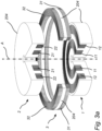
- Figs 6 , 7 , and 8 are cut-out perspective views of another plasma confinement device 500 comprising a first 1 a second 2, and a third 3 magnet system as detailed above in conjunction with Fig. 13 .
- the plasma confinement device 500 may be used in a fusion reactor.
- the plasma confinement device 500 may comprise a plasma vessel 208, as well-known per se in plasma fusion technology.
- a plasma vessel 208 may be located radially inside the coils 31, 32 of the third magnet system 3, radially inside the outer coils 22, 12 of, respectively, the first magnet system 1 and the second magnet system 2, and radially outside and axially inside the inner coils 11, 21 of, respectively, the first magnet system 1 and the second magnet system 2.
- Fig. 7 shows the ferromagnetic embedding 204.
- Fig. 8 shoes the plasma confinement device 500 being contained in a housing 1500.
- Typical dimensions may be as follows. Including the housing 1500, the device 500 may have diameter of about 25 m and a height of about 35 m. The inner diameter of the coils of the third magnet system 3 may be about 12 m. The minimal distance between the inner coils 11, 21 of, respectively, the first magnet system 1 and the second magnet system 2, may be about 11m.
- the overall current in a system of particles, i.e., plasma, confined therein may be zero, or close to zero. This may result in a much less dynamic plasma compared to the toroidal based reactors, such as tokamaks. Such a less dynamic plasma may have less problems with current-driven plasma instabilities, such as kink instability.
- an alpha particle If an alpha particle can be confined, it will contribute to the heating of the plasma so that an ignited plasma is self-sustained by confined alpha particles. Burning plasma needs external energy, but less than the heating energy produced by the fusion process. Such heating is provided by fusion-product alpha-particles. Thus, confining alpha particles is important.
- Deuterium and tritium will fuse at 12 keV or even lower. To confine a lighter ion at a lower energy is much easier than the heavy ion at high energy. If fusion-product alpha particles may be confined, deuterium and tritium ions as well as the electrons will also be confined in the same volume, i.e., if the alpha particles are confined, deuterium and tritium ions will also be confined.
- Simulations were performed of trajectories of charged particles with in a magnetic field computed by finite element method (FEM) simulation, verifying the capability of charged particle confinement.
- FEM finite element method
- a first quadrant (cf. Figs 4b , 9-13 ) could fully define the whole volume of the system.
- Particle trajectories were calculated iteratively, taking into account the Lorentz force on the particle and Newton's second law.
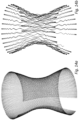
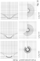
- Figs 14a, 14b , 15 , 16 , and 17 show one-particle simulation results in the configuration discussed above in conjunction with Figs 6 , 7 , 8 , and 13 .
- Fig. 14a shows the simulated path of a deuteron with a kinetic energy of 100 keV
- Fig. 14b shows the simulated path of an alpha particle with a kinetic energy of 3.5 MeV, i.e., as typical as a product from a fusion between a deuterium ion and a tritium ion.
- Both particles are confined in the plasma confinement area, being magnetically reflected at respective endpoints.
- the gyrocenter of the charged particles will follow a given field line and be reflected at the same endpoint regardless of the particle kinetic energy or charge.
- the particles will different gyro spin radii (Larmor radius), the drift will be different.
- Figs 15 , 16 , and 17 show, respectively, simulated charged particle trajectories with initial radial positions of 1.5 m, 3.0 m, and 4.5 m, each for v z /v R (axial velocity to radial velocity) ratios of 0.5, 1.5, 2.5, showing confinement of charged particles for each of these configurations.
Landscapes
- Physics & Mathematics (AREA)
- Engineering & Computer Science (AREA)
- Plasma & Fusion (AREA)
- General Engineering & Computer Science (AREA)
- High Energy & Nuclear Physics (AREA)
- Spectroscopy & Molecular Physics (AREA)
- Optics & Photonics (AREA)
- Plasma Technology (AREA)
- Physical Vapour Deposition (AREA)
- Particle Accelerators (AREA)
Claims (8)
- Magnetspiegelmaschine (2100; 2200; 3100; 3200) zum Plasmaeinschluss, mit einer Vielzahl von längs angeordneten Supraleiterspulen (2104, 2105, 2106a, 2106b), die zur Erzeugung eines Freifeld-Plasmaeinschlussbereichs (2106) angeordnet sind, wobei der Plasmaeinschlussbereich (2106) an jedem der beiden Enden durch einen jeweiligen Spiegelbereich (2108) mit erhöhter magnetischer Flussdichte relativ zu einem zentralen Bereich (2110) des Plasmaeinschlussbereichs (2106) begrenzt ist, wobei eine Supraleiterspule (2105, 2106a, 2106b) aus der Vielzahl von Supraleiterspulen an den Spiegelbereich (2108) grenzt und die Supraleiterspule (2105, 2106a, 2106b) einen Querschnitt aufweist, in einer Ebene, die eine Magnetfeldlinie (2112) durch den Spiegelbereich schneidet, mit einer länglichen Form in einer Richtung entlang der Magnetfeldlinie (2112), wobei die Vielzahl von Supraleiterspulen umfasst:
ein erstes Magnetsystem, das eine erste Vielzahl konzentrisch angeordneter kreisförmiger Supraleiterspulen umfasst, mit:einer ersten supraleitenden Spule (2206a), die so angeordnet ist, dass sie einen Strom in einer ersten Richtung führt; undeiner zweiten supraleitenden Spule (2206b), die so angeordnet ist, dass sie einen Strom in einer zweiten Richtung entgegengesetzt zur ersten Richtung führt; undeinem zweiten Magnetsystem, das eine zweite Vielzahl konzentrisch angeordneter kreisförmiger Spulen umfasst, die spiegelsymmetrisch zum ersten Magnetsystem in Bezug auf eine Symmetrieebene (P) angeordnet sind, die sich zwischen dem ersten Magnetsystem und dem zweiten Magnetsystem befindet. - Magnetspiegelmaschine nach Anspruch 1, wobei ein Umfangssegment (2107b) der Querschnittsfläche, das auf die Spiegelfläche (2108) gerichtet ist, von außerhalb des Umfangssegments (2107b) gesehen konvex ist.
- Magnetspiegelmaschine nach einem der Ansprüche 1-2, wobei ein Umfangssegment (2107a) der Querschnittsfläche, das von der Spiegelfläche (2108) weg gerichtet ist, von außerhalb des Umfangssegments (2107a) gesehen konkav ist.
- Magnetspiegelmaschine nach einem der Ansprüche 1-3, wobei ein Umfangssegment (2107b) der Querschnittsfläche, das auf den Spiegelbereich (2108) gerichtet ist, parallel zu einem Umfangssegment (2107a) der Querschnittsfläche verläuft, das vom Spiegelbereich (2108) weg gerichtet ist.
- Magnetspiegelmaschine nach einem der vorhergehenden Ansprüche, wobei die Vielzahl von Supraleiterspulen ferner ein drittes Magnetsystem (2104) umfasst, das radial außerhalb des Plasmaeinschlussbereichs angeordnet ist, wobei das dritte Magnetsystem mindestens eine Supraleiter-Ringschleifenspule umfasst.
- Fusionsreaktor mit der Magnetspiegelmaschine nach einem der Ansprüche 1-5.
- Verwendung der Magnetspiegelmaschine nach einem der Ansprüche 1-5 zum Einschließen eines Plasmas.
- Verwendung der Magnetspiegelmaschine nach einem der Ansprüche 1-5 in einem Fusionsreaktor.
Applications Claiming Priority (3)
| Application Number | Priority Date | Filing Date | Title |
|---|---|---|---|
| EP19208258.4A EP3819913A1 (de) | 2019-11-11 | 2019-11-11 | Plasmaeinschlussvorrichtung und verfahren zum plasmaeinschluss |
| PCT/EP2020/081762 WO2021094372A1 (en) | 2019-11-11 | 2020-11-11 | Plasma confinement device and method for plasma confinement |
| PCT/EP2021/081409 WO2022101356A1 (en) | 2019-11-11 | 2021-11-11 | Magnetic mirror machine |
Publications (3)
| Publication Number | Publication Date |
|---|---|
| EP4244871A1 EP4244871A1 (de) | 2023-09-20 |
| EP4244871B1 true EP4244871B1 (de) | 2024-12-04 |
| EP4244871C0 EP4244871C0 (de) | 2024-12-04 |
Family
ID=68531413
Family Applications (3)
| Application Number | Title | Priority Date | Filing Date |
|---|---|---|---|
| EP19208258.4A Withdrawn EP3819913A1 (de) | 2019-11-11 | 2019-11-11 | Plasmaeinschlussvorrichtung und verfahren zum plasmaeinschluss |
| EP20803566.7A Active EP4059029B1 (de) | 2019-11-11 | 2020-11-11 | Plasmaeinschlussvorrichtung und verfahren zum plasmaeinschluss |
| EP21810604.5A Active EP4244871B1 (de) | 2019-11-11 | 2021-11-11 | Magnetspiegelmaschine |
Family Applications Before (2)
| Application Number | Title | Priority Date | Filing Date |
|---|---|---|---|
| EP19208258.4A Withdrawn EP3819913A1 (de) | 2019-11-11 | 2019-11-11 | Plasmaeinschlussvorrichtung und verfahren zum plasmaeinschluss |
| EP20803566.7A Active EP4059029B1 (de) | 2019-11-11 | 2020-11-11 | Plasmaeinschlussvorrichtung und verfahren zum plasmaeinschluss |
Country Status (11)
| Country | Link |
|---|---|
| US (2) | US12266452B2 (de) |
| EP (3) | EP3819913A1 (de) |
| JP (2) | JP7585338B2 (de) |
| KR (2) | KR20220092897A (de) |
| CN (2) | CN114667575A (de) |
| BR (1) | BR112022008006A2 (de) |
| CA (2) | CA3160621A1 (de) |
| ES (2) | ES3010232T3 (de) |
| MX (2) | MX2022005487A (de) |
| PL (2) | PL4059029T3 (de) |
| WO (2) | WO2021094372A1 (de) |
Families Citing this family (10)
| Publication number | Priority date | Publication date | Assignee | Title |
|---|---|---|---|---|
| EP3819913A1 (de) * | 2019-11-11 | 2021-05-12 | JFP Jäderberg Fusion Power AB | Plasmaeinschlussvorrichtung und verfahren zum plasmaeinschluss |
| EP4299284A4 (de) * | 2021-02-24 | 2024-05-15 | Sumitomo Electric Fine Polymer, Inc. | Wärmeschrumpfbarer schlauch, wärmeschrumpfbare kopplungskomponente, herstellungsverfahren für wärmeschrumpfbaren schlauch und herstellungsverfahren für wärmeschrumpfbare kopplungskomponente |
| CN115798741A (zh) * | 2022-12-16 | 2023-03-14 | 上海交通大学 | 一种激光聚变点火靶双锥装配观测及调整系统 |
| EP4394798A1 (de) * | 2022-12-29 | 2024-07-03 | Novatron Fusion Group AB | Magnetspiegelmaschine |
| EP4394799A1 (de) * | 2022-12-29 | 2024-07-03 | Novatron Fusion Group AB | Magnetspiegelmaschine |
| CN115988725A (zh) * | 2023-02-17 | 2023-04-18 | 哈尔滨工业大学 | 一种用于高真空等离子体环境的磁体位置调节机构 |
| EP4489037A1 (de) | 2023-07-05 | 2025-01-08 | Novatron Fusion Group AB | Elektromagnetische spule |
| EP4657461A1 (de) * | 2024-05-26 | 2025-12-03 | Novatron Fusion Group AB | Magnetspiegelmaschine |
| EP4664489A1 (de) * | 2024-06-10 | 2025-12-17 | Novatron Fusion Group AB | Magnetspiegelmaschine |
| CN119935909B (zh) * | 2025-01-09 | 2025-09-30 | 核工业西南物理研究院 | 一种利用主动光谱测量杂质裸核浓度剖面的方法 |
Family Cites Families (41)
| Publication number | Priority date | Publication date | Assignee | Title |
|---|---|---|---|---|
| US3664921A (en) * | 1969-10-16 | 1972-05-23 | Atomic Energy Commission | Proton e-layer astron for producing controlled fusion reactions |
| US3582849A (en) * | 1969-12-03 | 1971-06-01 | Atomic Energy Commission | Electromagnetic apparatus for producing and containing high temperature plasmas |
| US3663360A (en) * | 1970-08-13 | 1972-05-16 | Atomic Energy Commission | Conversion of high temperature plasma energy into electrical energy |
| US3634704A (en) * | 1970-09-02 | 1972-01-11 | Atomic Energy Commission | Apparatus for the production of highly stripped ions |
| US3668065A (en) * | 1970-09-15 | 1972-06-06 | Atomic Energy Commission | Apparatus for the conversion of high temperature plasma energy into electrical energy |
| US3779864A (en) * | 1971-10-29 | 1973-12-18 | Atomic Energy Commission | External control of ion waves in a plasma by high frequency fields |
| USH554H (en) * | 1972-03-02 | 1988-12-06 | The United States Of America As Represented By The United States Department Of Energy | Toroidal reactor |
| US4125431A (en) * | 1977-06-16 | 1978-11-14 | The United States Of America As Represented By The United States Department Of Energy | Tandem mirror plasma confinement apparatus |
| US4166760A (en) * | 1977-10-04 | 1979-09-04 | The United States Of America As Represented By The United States Department Of Energy | Plasma confinement apparatus using solenoidal and mirror coils |
| US4237507A (en) * | 1978-07-11 | 1980-12-02 | Gosudarstvenny Nauchnoissledovatelsky Energetichesky Institut Imeni G. M. Krzhizhanovskogo | Superconducting magnetic system |
| US4252608A (en) * | 1979-03-16 | 1981-02-24 | The United States Of America As Represented By The United States Department Of Energy | Generating end plug potentials in tandem mirror plasma confinement by heating thermal particles so as to escape low density end stoppering plasmas |
| US4735762A (en) * | 1983-09-29 | 1988-04-05 | The United States Of America As Represented By The United States Department Of Energy | Laser or charged-particle-beam fusion reactor with direct electric generation by magnetic flux compression |
| JPH01161189A (ja) * | 1987-12-18 | 1989-06-23 | Toshiba Corp | 核融合装置 |
| US5114913A (en) * | 1988-02-12 | 1992-05-19 | International Business Machines Corporation | Magnetic head slider employing superconductor for levitation |
| JP2618001B2 (ja) * | 1988-07-13 | 1997-06-11 | 三菱電機株式会社 | プラズマ反応装置 |
| US5082827A (en) * | 1990-06-01 | 1992-01-21 | University Of Colorado Foundation, Inc. | Recording head suspension utilizing superconductor means |
| US5779802A (en) * | 1990-12-10 | 1998-07-14 | Imec V.Z.W. | Thin film deposition chamber with ECR-plasma source |
| US6664740B2 (en) * | 2001-02-01 | 2003-12-16 | The Regents Of The University Of California | Formation of a field reversed configuration for magnetic and electrostatic confinement of plasma |
| US6611106B2 (en) * | 2001-03-19 | 2003-08-26 | The Regents Of The University Of California | Controlled fusion in a field reversed configuration and direct energy conversion |
| GB2461267B (en) * | 2008-06-24 | 2012-05-30 | Stephen Thomas Brookes | Improvements in or relating to nuclear fusion |
| US8624502B2 (en) * | 2009-05-15 | 2014-01-07 | Alpha Source Llc | Particle beam source apparatus, system and method |
| DK3223284T3 (da) * | 2011-11-14 | 2019-05-20 | Univ California | Fremgangsmåde til dannelse og opretholdelse af højydelses-frc |
| US9947420B2 (en) * | 2013-04-03 | 2018-04-17 | Lockheed Martin Corporation | Magnetic field plasma confinement for compact fusion power |
| US9934876B2 (en) * | 2013-04-03 | 2018-04-03 | Lockheed Martin Corporation | Magnetic field plasma confinement for compact fusion power |
| WO2017083796A1 (en) * | 2015-11-13 | 2017-05-18 | Tri Alpha Energy, Inc. | Systems and methods for frc plasma position stability |
| WO2018093941A1 (en) * | 2016-11-15 | 2018-05-24 | Tae Technologies, Inc. | Systems and methods for improved sustainment of a high performance frc and high harmonic fast wave electron heating in a high performance frc |
| SG11201907338VA (en) * | 2017-02-12 | 2019-09-27 | Brilliant Light Power Inc | Magnetohydrodynamic electric power generator |
| US20180254153A1 (en) * | 2017-03-02 | 2018-09-06 | Mikiso Mizuki | Apparatus for plasma confinement and for ion separation |
| US20180277259A1 (en) * | 2017-03-27 | 2018-09-27 | Jerry I. Jacobson | Method and apparatus for controlled thermonuclear fusion power |
| US20200077507A1 (en) * | 2017-04-21 | 2020-03-05 | Massachusetts Institute Of Technology | DC Constant-Field Synchrotron Providing Inverse Reflection of Charged Particles |
| US11744002B2 (en) * | 2017-09-12 | 2023-08-29 | University Of New Hampshire | System of converging plasma pistons |
| US10784001B2 (en) * | 2018-01-17 | 2020-09-22 | Lockheed Martin Corporation | Passive magnetic shielding of structures immersed in plasma using superconductors |
| GB201810512D0 (en) * | 2018-06-27 | 2018-08-15 | Tokamak Energy Ltd | Double null liquid metal divertors |
| US11482342B2 (en) * | 2018-10-07 | 2022-10-25 | Tanner L. Horne | Nuclear fusion reactor with toroidal superconducting magnetic coils implementing inertial electrostatic heating |
| WO2020148709A2 (en) * | 2019-01-18 | 2020-07-23 | Brilliant Light Power, Inc. | Magnetohydrodynamic hydrogen electrical power generator |
| US11164681B2 (en) * | 2019-03-05 | 2021-11-02 | The Trustees Of Princeton University | System and method for reducing heat loss from FRC bulk plasma |
| EP3819913A1 (de) * | 2019-11-11 | 2021-05-12 | JFP Jäderberg Fusion Power AB | Plasmaeinschlussvorrichtung und verfahren zum plasmaeinschluss |
| US10966310B1 (en) * | 2020-04-03 | 2021-03-30 | Wisconsin Alumni Research Foundation | High-energy plasma generator using radio-frequency and neutral beam power |
| JP2025509076A (ja) * | 2022-03-14 | 2025-04-11 | ザ、トラスティーズ オブ プリンストン ユニバーシティ | ステラレータ中性子源のためのシステム及び方法 |
| US12166398B2 (en) * | 2022-03-15 | 2024-12-10 | Wisconsin Alumni Research Foundation | Direct energy converter for axisymmetric mirror fusion reactor |
| CN117457240B (zh) * | 2023-12-25 | 2024-03-26 | 中国科学院合肥物质科学研究院 | 一种磁约束聚变反应堆 |
-
2019
- 2019-11-11 EP EP19208258.4A patent/EP3819913A1/de not_active Withdrawn
-
2020
- 2020-11-11 CA CA3160621A patent/CA3160621A1/en active Pending
- 2020-11-11 KR KR1020227016181A patent/KR20220092897A/ko active Pending
- 2020-11-11 CN CN202080079632.5A patent/CN114667575A/zh active Pending
- 2020-11-11 EP EP20803566.7A patent/EP4059029B1/de active Active
- 2020-11-11 BR BR112022008006A patent/BR112022008006A2/pt unknown
- 2020-11-11 JP JP2022553218A patent/JP7585338B2/ja active Active
- 2020-11-11 PL PL20803566.7T patent/PL4059029T3/pl unknown
- 2020-11-11 ES ES20803566T patent/ES3010232T3/es active Active
- 2020-11-11 WO PCT/EP2020/081762 patent/WO2021094372A1/en not_active Ceased
- 2020-11-11 US US17/771,684 patent/US12266452B2/en active Active
- 2020-11-11 MX MX2022005487A patent/MX2022005487A/es unknown
-
2021
- 2021-11-11 CN CN202180044436.9A patent/CN115867985A/zh active Pending
- 2021-11-11 US US18/010,364 patent/US20240013932A1/en active Pending
- 2021-11-11 MX MX2022016313A patent/MX2022016313A/es unknown
- 2021-11-11 PL PL21810604.5T patent/PL4244871T3/pl unknown
- 2021-11-11 KR KR1020227045094A patent/KR102832371B1/ko active Active
- 2021-11-11 ES ES21810604T patent/ES3014381T3/es active Active
- 2021-11-11 EP EP21810604.5A patent/EP4244871B1/de active Active
- 2021-11-11 CA CA3180392A patent/CA3180392A1/en active Pending
- 2021-11-11 JP JP2022580093A patent/JP2023547297A/ja active Pending
- 2021-11-11 WO PCT/EP2021/081409 patent/WO2022101356A1/en not_active Ceased
Also Published As
| Publication number | Publication date |
|---|---|
| EP4059029C0 (de) | 2024-11-06 |
| KR20230011431A (ko) | 2023-01-20 |
| PL4244871T3 (pl) | 2025-04-07 |
| JP7585338B2 (ja) | 2024-11-18 |
| BR112022008006A2 (pt) | 2022-07-12 |
| WO2022101356A1 (en) | 2022-05-19 |
| MX2022016313A (es) | 2023-01-24 |
| US12266452B2 (en) | 2025-04-01 |
| US20220367069A1 (en) | 2022-11-17 |
| KR102832371B1 (ko) | 2025-07-09 |
| CA3160621A1 (en) | 2021-05-20 |
| US20240013932A1 (en) | 2024-01-11 |
| PL4059029T3 (pl) | 2025-04-14 |
| ES3010232T3 (en) | 2025-04-01 |
| CA3180392A1 (en) | 2022-05-19 |
| EP3819913A1 (de) | 2021-05-12 |
| EP4244871C0 (de) | 2024-12-04 |
| EP4244871A1 (de) | 2023-09-20 |
| EP4059029A1 (de) | 2022-09-21 |
| MX2022005487A (es) | 2022-06-02 |
| JP2023547297A (ja) | 2023-11-10 |
| EP4059029B1 (de) | 2024-11-06 |
| CN115867985A (zh) | 2023-03-28 |
| ES3014381T3 (en) | 2025-04-22 |
| KR20220092897A (ko) | 2022-07-04 |
| JP2023502173A (ja) | 2023-01-20 |
| CN114667575A (zh) | 2022-06-24 |
| WO2021094372A1 (en) | 2021-05-20 |
Similar Documents
| Publication | Publication Date | Title |
|---|---|---|
| EP4244871B1 (de) | Magnetspiegelmaschine | |
| Liu et al. | Magnetic configuration and modular coil design for the Chinese first quasi-axisymmetric stellarator | |
| EP0081952B1 (de) | Multipol Pinchverfahren und Vorrichtung zur Erzeugung einer mittleren magnetischen Mulde zum Plasmaeinschluss | |
| KR101052579B1 (ko) | Frc의 자계에서 플라즈마 이온들 및 전자들을 드라이브하는 시스템 및 방법 | |
| Tang et al. | Concept for a future super proton-proton collider | |
| US4166760A (en) | Plasma confinement apparatus using solenoidal and mirror coils | |
| EA006320B1 (ru) | Контролируемый ядерный синтез в конфигурации с обращенным полем и прямое преобразование энергии | |
| CN113539524A (zh) | 保持高性能等离子体的装置和方法 | |
| Yamada et al. | Initial results from investigation of three‐dimensional magnetic reconnection in a laboratory plasma | |
| US3219534A (en) | Plasma confinement apparatus employing a helical magnetic field configuration | |
| US20240096509A1 (en) | Electromagnetic confinement of plasma in a controlled fusion reactor | |
| EP3997716B1 (de) | Abschirmungsstrukturen in einer plasmaumgebung | |
| EP4664489A1 (de) | Magnetspiegelmaschine | |
| EP4657461A1 (de) | Magnetspiegelmaschine | |
| EP4394799A1 (de) | Magnetspiegelmaschine | |
| EP4394798A1 (de) | Magnetspiegelmaschine | |
| EP1785999A1 (de) | Kugelförmiger Fusionsreaktor und Verfahren zur Aufrecherhaltung oder Initiierung einer Fusion | |
| GARZA-ULLOA | Author of the book: Applied Biomechatronics Using Mathematical Models University of Texas At El Paso: jgarzaulloa@ miners. utep. edu-Research Consulting Services: jorge@ garzaulloa. org | |
| Chen | Multipoles and Surmacs II: Engineering | |
| Huguet et al. | The Joint European Torus-Engineering aspects of the JET nuclear fusion project | |
| Ulloa | Electromagnetic Field Toroidal Equations Applied to Magnetic Confinement Fusion as Tokamak |
Legal Events
| Date | Code | Title | Description |
|---|---|---|---|
| STAA | Information on the status of an ep patent application or granted ep patent |
Free format text: STATUS: UNKNOWN |
|
| STAA | Information on the status of an ep patent application or granted ep patent |
Free format text: STATUS: THE INTERNATIONAL PUBLICATION HAS BEEN MADE |
|
| PUAI | Public reference made under article 153(3) epc to a published international application that has entered the european phase |
Free format text: ORIGINAL CODE: 0009012 |
|
| STAA | Information on the status of an ep patent application or granted ep patent |
Free format text: STATUS: REQUEST FOR EXAMINATION WAS MADE |
|
| 17P | Request for examination filed |
Effective date: 20221222 |
|
| AK | Designated contracting states |
Kind code of ref document: A1 Designated state(s): AL AT BE BG CH CY CZ DE DK EE ES FI FR GB GR HR HU IE IS IT LI LT LU LV MC MK MT NL NO PL PT RO RS SE SI SK SM TR |
|
| DAV | Request for validation of the european patent (deleted) | ||
| DAX | Request for extension of the european patent (deleted) | ||
| GRAP | Despatch of communication of intention to grant a patent |
Free format text: ORIGINAL CODE: EPIDOSNIGR1 |
|
| STAA | Information on the status of an ep patent application or granted ep patent |
Free format text: STATUS: GRANT OF PATENT IS INTENDED |
|
| INTG | Intention to grant announced |
Effective date: 20240624 |
|
| GRAS | Grant fee paid |
Free format text: ORIGINAL CODE: EPIDOSNIGR3 |
|
| GRAA | (expected) grant |
Free format text: ORIGINAL CODE: 0009210 |
|
| STAA | Information on the status of an ep patent application or granted ep patent |
Free format text: STATUS: THE PATENT HAS BEEN GRANTED |
|
| AK | Designated contracting states |
Kind code of ref document: B1 Designated state(s): AL AT BE BG CH CY CZ DE DK EE ES FI FR GB GR HR HU IE IS IT LI LT LU LV MC MK MT NL NO PL PT RO RS SE SI SK SM TR |
|
| REG | Reference to a national code |
Ref country code: CH Ref legal event code: EP |
|
| REG | Reference to a national code |
Ref country code: DE Ref legal event code: R096 Ref document number: 602021023012 Country of ref document: DE |
|
| REG | Reference to a national code |
Ref country code: IE Ref legal event code: FG4D |
|
| U01 | Request for unitary effect filed |
Effective date: 20241219 |
|
| U07 | Unitary effect registered |
Designated state(s): AT BE BG DE DK EE FI FR IT LT LU LV MT NL PT RO SE SI Effective date: 20250110 |
|
| REG | Reference to a national code |
Ref country code: SK Ref legal event code: T3 Ref document number: E 45960 Country of ref document: SK |
|
| PG25 | Lapsed in a contracting state [announced via postgrant information from national office to epo] |
Ref country code: HR Free format text: LAPSE BECAUSE OF FAILURE TO SUBMIT A TRANSLATION OF THE DESCRIPTION OR TO PAY THE FEE WITHIN THE PRESCRIBED TIME-LIMIT Effective date: 20241204 |
|
| REG | Reference to a national code |
Ref country code: ES Ref legal event code: FG2A Ref document number: 3014381 Country of ref document: ES Kind code of ref document: T3 Effective date: 20250422 |
|
| PG25 | Lapsed in a contracting state [announced via postgrant information from national office to epo] |
Ref country code: GR Free format text: LAPSE BECAUSE OF FAILURE TO SUBMIT A TRANSLATION OF THE DESCRIPTION OR TO PAY THE FEE WITHIN THE PRESCRIBED TIME-LIMIT Effective date: 20250305 |
|
| PG25 | Lapsed in a contracting state [announced via postgrant information from national office to epo] |
Ref country code: RS Free format text: LAPSE BECAUSE OF FAILURE TO SUBMIT A TRANSLATION OF THE DESCRIPTION OR TO PAY THE FEE WITHIN THE PRESCRIBED TIME-LIMIT Effective date: 20250304 |
|
| PG25 | Lapsed in a contracting state [announced via postgrant information from national office to epo] |
Ref country code: SM Free format text: LAPSE BECAUSE OF FAILURE TO SUBMIT A TRANSLATION OF THE DESCRIPTION OR TO PAY THE FEE WITHIN THE PRESCRIBED TIME-LIMIT Effective date: 20241204 |
|
| PG25 | Lapsed in a contracting state [announced via postgrant information from national office to epo] |
Ref country code: IS Free format text: LAPSE BECAUSE OF FAILURE TO SUBMIT A TRANSLATION OF THE DESCRIPTION OR TO PAY THE FEE WITHIN THE PRESCRIBED TIME-LIMIT Effective date: 20250404 |
|
| PLBE | No opposition filed within time limit |
Free format text: ORIGINAL CODE: 0009261 |
|
| STAA | Information on the status of an ep patent application or granted ep patent |
Free format text: STATUS: NO OPPOSITION FILED WITHIN TIME LIMIT |
|
| REG | Reference to a national code |
Ref country code: CH Ref legal event code: L10 Free format text: ST27 STATUS EVENT CODE: U-0-0-L10-L00 (AS PROVIDED BY THE NATIONAL OFFICE) Effective date: 20251015 |
|
| 26N | No opposition filed |
Effective date: 20250905 |
|
| U20 | Renewal fee for the european patent with unitary effect paid |
Year of fee payment: 5 Effective date: 20251016 |
|
| REG | Reference to a national code |
Ref country code: CH Ref legal event code: U11 Free format text: ST27 STATUS EVENT CODE: U-0-0-U10-U11 (AS PROVIDED BY THE NATIONAL OFFICE) Effective date: 20251201 |
|
| PGFP | Annual fee paid to national office [announced via postgrant information from national office to epo] |
Ref country code: GB Payment date: 20251016 Year of fee payment: 5 |
|
| PGFP | Annual fee paid to national office [announced via postgrant information from national office to epo] |
Ref country code: NO Payment date: 20251021 Year of fee payment: 5 |
|
| PGFP | Annual fee paid to national office [announced via postgrant information from national office to epo] |
Ref country code: TR Payment date: 20251104 Year of fee payment: 5 |
|
| PGFP | Annual fee paid to national office [announced via postgrant information from national office to epo] |
Ref country code: CH Payment date: 20251201 Year of fee payment: 5 |
|
| PGFP | Annual fee paid to national office [announced via postgrant information from national office to epo] |
Ref country code: CZ Payment date: 20251105 Year of fee payment: 5 Ref country code: IE Payment date: 20251013 Year of fee payment: 5 |
|
| PGFP | Annual fee paid to national office [announced via postgrant information from national office to epo] |
Ref country code: PL Payment date: 20251015 Year of fee payment: 5 |
|
| PGFP | Annual fee paid to national office [announced via postgrant information from national office to epo] |
Ref country code: SK Payment date: 20251104 Year of fee payment: 5 |
|
| PGFP | Annual fee paid to national office [announced via postgrant information from national office to epo] |
Ref country code: ES Payment date: 20251201 Year of fee payment: 5 |