EP4244653B1 - Système lidar à contrôleur de puissance optique d'émission - Google Patents
Système lidar à contrôleur de puissance optique d'émission Download PDFInfo
- Publication number
- EP4244653B1 EP4244653B1 EP21892689.7A EP21892689A EP4244653B1 EP 4244653 B1 EP4244653 B1 EP 4244653B1 EP 21892689 A EP21892689 A EP 21892689A EP 4244653 B1 EP4244653 B1 EP 4244653B1
- Authority
- EP
- European Patent Office
- Prior art keywords
- optical
- light
- transmitter
- monitor
- beams
- Prior art date
- Legal status (The legal status is an assumption and is not a legal conclusion. Google has not performed a legal analysis and makes no representation as to the accuracy of the status listed.)
- Active
Links
Images

Classifications
-
- G—PHYSICS
- G01—MEASURING; TESTING
- G01S—RADIO DIRECTION-FINDING; RADIO NAVIGATION; DETERMINING DISTANCE OR VELOCITY BY USE OF RADIO WAVES; LOCATING OR PRESENCE-DETECTING BY USE OF THE REFLECTION OR RERADIATION OF RADIO WAVES; ANALOGOUS ARRANGEMENTS USING OTHER WAVES
- G01S7/00—Details of systems according to groups G01S13/00, G01S15/00, G01S17/00
- G01S7/48—Details of systems according to groups G01S13/00, G01S15/00, G01S17/00 of systems according to group G01S17/00
- G01S7/497—Means for monitoring or calibrating
-
- G—PHYSICS
- G01—MEASURING; TESTING
- G01S—RADIO DIRECTION-FINDING; RADIO NAVIGATION; DETERMINING DISTANCE OR VELOCITY BY USE OF RADIO WAVES; LOCATING OR PRESENCE-DETECTING BY USE OF THE REFLECTION OR RERADIATION OF RADIO WAVES; ANALOGOUS ARRANGEMENTS USING OTHER WAVES
- G01S17/00—Systems using the reflection or reradiation of electromagnetic waves other than radio waves, e.g. lidar systems
- G01S17/02—Systems using the reflection of electromagnetic waves other than radio waves
- G01S17/06—Systems determining position data of a target
- G01S17/08—Systems determining position data of a target for measuring distance only
- G01S17/10—Systems determining position data of a target for measuring distance only using transmission of interrupted, pulse-modulated waves
-
- G—PHYSICS
- G01—MEASURING; TESTING
- G01S—RADIO DIRECTION-FINDING; RADIO NAVIGATION; DETERMINING DISTANCE OR VELOCITY BY USE OF RADIO WAVES; LOCATING OR PRESENCE-DETECTING BY USE OF THE REFLECTION OR RERADIATION OF RADIO WAVES; ANALOGOUS ARRANGEMENTS USING OTHER WAVES
- G01S17/00—Systems using the reflection or reradiation of electromagnetic waves other than radio waves, e.g. lidar systems
- G01S17/88—Lidar systems specially adapted for specific applications
- G01S17/89—Lidar systems specially adapted for specific applications for mapping or imaging
-
- G—PHYSICS
- G01—MEASURING; TESTING
- G01S—RADIO DIRECTION-FINDING; RADIO NAVIGATION; DETERMINING DISTANCE OR VELOCITY BY USE OF RADIO WAVES; LOCATING OR PRESENCE-DETECTING BY USE OF THE REFLECTION OR RERADIATION OF RADIO WAVES; ANALOGOUS ARRANGEMENTS USING OTHER WAVES
- G01S17/00—Systems using the reflection or reradiation of electromagnetic waves other than radio waves, e.g. lidar systems
- G01S17/88—Lidar systems specially adapted for specific applications
- G01S17/93—Lidar systems specially adapted for specific applications for anti-collision purposes
- G01S17/931—Lidar systems specially adapted for specific applications for anti-collision purposes of land vehicles
-
- G—PHYSICS
- G01—MEASURING; TESTING
- G01S—RADIO DIRECTION-FINDING; RADIO NAVIGATION; DETERMINING DISTANCE OR VELOCITY BY USE OF RADIO WAVES; LOCATING OR PRESENCE-DETECTING BY USE OF THE REFLECTION OR RERADIATION OF RADIO WAVES; ANALOGOUS ARRANGEMENTS USING OTHER WAVES
- G01S7/00—Details of systems according to groups G01S13/00, G01S15/00, G01S17/00
- G01S7/48—Details of systems according to groups G01S13/00, G01S15/00, G01S17/00 of systems according to group G01S17/00
- G01S7/481—Constructional features, e.g. arrangements of optical elements
- G01S7/4811—Constructional features, e.g. arrangements of optical elements common to transmitter and receiver
-
- G—PHYSICS
- G01—MEASURING; TESTING
- G01S—RADIO DIRECTION-FINDING; RADIO NAVIGATION; DETERMINING DISTANCE OR VELOCITY BY USE OF RADIO WAVES; LOCATING OR PRESENCE-DETECTING BY USE OF THE REFLECTION OR RERADIATION OF RADIO WAVES; ANALOGOUS ARRANGEMENTS USING OTHER WAVES
- G01S7/00—Details of systems according to groups G01S13/00, G01S15/00, G01S17/00
- G01S7/48—Details of systems according to groups G01S13/00, G01S15/00, G01S17/00 of systems according to group G01S17/00
- G01S7/481—Constructional features, e.g. arrangements of optical elements
- G01S7/4814—Constructional features, e.g. arrangements of optical elements of transmitters alone
- G01S7/4815—Constructional features, e.g. arrangements of optical elements of transmitters alone using multiple transmitters
-
- G—PHYSICS
- G01—MEASURING; TESTING
- G01S—RADIO DIRECTION-FINDING; RADIO NAVIGATION; DETERMINING DISTANCE OR VELOCITY BY USE OF RADIO WAVES; LOCATING OR PRESENCE-DETECTING BY USE OF THE REFLECTION OR RERADIATION OF RADIO WAVES; ANALOGOUS ARRANGEMENTS USING OTHER WAVES
- G01S7/00—Details of systems according to groups G01S13/00, G01S15/00, G01S17/00
- G01S7/48—Details of systems according to groups G01S13/00, G01S15/00, G01S17/00 of systems according to group G01S17/00
- G01S7/483—Details of pulse systems
- G01S7/486—Receivers
- G01S7/4868—Controlling received signal intensity or exposure of sensor
-
- G—PHYSICS
- G01—MEASURING; TESTING
- G01S—RADIO DIRECTION-FINDING; RADIO NAVIGATION; DETERMINING DISTANCE OR VELOCITY BY USE OF RADIO WAVES; LOCATING OR PRESENCE-DETECTING BY USE OF THE REFLECTION OR RERADIATION OF RADIO WAVES; ANALOGOUS ARRANGEMENTS USING OTHER WAVES
- G01S7/00—Details of systems according to groups G01S13/00, G01S15/00, G01S17/00
- G01S7/48—Details of systems according to groups G01S13/00, G01S15/00, G01S17/00 of systems according to group G01S17/00
- G01S7/491—Details of non-pulse systems
- G01S7/4912—Receivers
- G01S7/4918—Controlling received signal intensity, gain or exposure of sensor
-
- H—ELECTRICITY
- H01—ELECTRIC ELEMENTS
- H01S—DEVICES USING THE PROCESS OF LIGHT AMPLIFICATION BY STIMULATED EMISSION OF RADIATION [LASER] TO AMPLIFY OR GENERATE LIGHT; DEVICES USING STIMULATED EMISSION OF ELECTROMAGNETIC RADIATION IN WAVE RANGES OTHER THAN OPTICAL
- H01S5/00—Semiconductor lasers
- H01S5/10—Construction or shape of the optical resonator, e.g. extended or external cavity, coupled cavities, bent-guide, varying width, thickness or composition of the active region
- H01S5/18—Surface-emitting [SE] lasers, e.g. having both horizontal and vertical cavities
- H01S5/183—Surface-emitting [SE] lasers, e.g. having both horizontal and vertical cavities having only vertical cavities, e.g. vertical cavity surface-emitting lasers [VCSEL]
-
- B—PERFORMING OPERATIONS; TRANSPORTING
- B60—VEHICLES IN GENERAL
- B60W—CONJOINT CONTROL OF VEHICLE SUB-UNITS OF DIFFERENT TYPE OR DIFFERENT FUNCTION; CONTROL SYSTEMS SPECIALLY ADAPTED FOR HYBRID VEHICLES; ROAD VEHICLE DRIVE CONTROL SYSTEMS FOR PURPOSES NOT RELATED TO THE CONTROL OF A PARTICULAR SUB-UNIT
- B60W2420/00—Indexing codes relating to the type of sensors based on the principle of their operation
- B60W2420/40—Photo, light or radio wave sensitive means, e.g. infrared sensors
- B60W2420/408—Radar; Laser, e.g. lidar
Definitions
- Autonomous, self-driving, and semi-autonomous automobiles use a combination of different sensors and technologies such as radar, image-recognition cameras, and sonar for detection and location of surrounding objects.
- sensors enable a host of improvements in driver safety including collision warning, automatic-emergency braking, lane-departure warning, lane-keeping assistance, adaptive cruise control, and piloted driving.
- LiDAR light detection and ranging
- US 4,722,599 A1 discloses a ceilometer operating according to a gating method that integrates output signals from a light receiver.
- US 2016/0172821 A1 discloses a VCSEL assembly including a VCSEL, an optical element, and an optical detector.
- a light detection and ranging transmitter with optical power monitoring is provided according to claim 1.
- Optional features of the first aspect of the invention are provided in dependent claims 2-10.
- a method of light detection and ranging with optical power monitoring is provided according to claim 11.
- Optional features of the second aspect of the invention are provided in dependent claims 12-15.
- the present teaching relates generally to Light Detection and Ranging (LiDAR), which is a remote sensing method that uses laser light to measure distances (ranges) to objects.
- LiDAR systems generally measure distances to various objects or targets that reflect and/or scatter light.
- Autonomous vehicles make use of LiDAR systems to generate a highly accurate 3D map of the surrounding environment with fine resolution.
- the systems and methods described herein are directed towards providing a solid-state, pulsed time-of-flight (TOF) LiDAR system with high levels of reliability, while also maintaining long measurement range as well as low cost.
- TOF pulsed time-of-flight
- LiDAR systems use a laser transmitter that includes a laser array.
- the laser array comprises Vertical Cavity Surface Emitting Laser (VCSEL) devices. These may include top-emitting VCSELs, bottom-emitting VCSELs, and various types of high-power VCSELs.
- VCSEL arrays may be monolithic.
- the laser emitters may all share a common substrate, including semiconductor substrates or ceramic substrates.
- individual lasers and/or groups of lasers using one or more transmitter arrays can be individually controlled. Each individual emitter in the transmitter array can be fired independently. The optical beam emitted by each laser emitter corresponds to a 3D projection angle subtending only a portion of the total system field-of-view.
- a LiDAR system is described in U.S. Patent Publication No. 2017/0307736 A1 .
- the number of pulses fired by an individual laser, or group of lasers can be controlled based on a desired performance objective of the LiDAR system. The duration and timing of this sequence can also be controlled to achieve various performance goals.
- LiDAR systems use detectors and/or groups of detectors in a detector array that can also be individually controlled. See, for example, U.S. Patent Publication No. US 2020/0386868 , entitled “Eye-Safe Long-Range Solid-State LiDAR System".
- This independent control over the individual lasers and/or groups of lasers in the transmitter array and/or over the detectors and/or groups of detectors in a detector array provide for various desirable operating features including control of the system field-of-view, optical power levels, and scanning pattern.
- US 4 722 599 discloses a device for measuring height of clouds, the device including a light transmitter consisting of an array of laser diodes.
- a transmitter control unit monitors the light output power of the laser diode array by means of a photodetector and regulates the amplitude of current pulses driving the laser diode array so as to keep the light output power constant.
- US 2016/0172821 discloses a VCSEL assembly which may include multiple VCSELs arranged in an array, a prism having an indentation, and an optical detector.
- a portion of the output light of the VCSEL array is reflected by the indentation towards the optical detector to be used for power monitoring.
- the optical detector is arranged at the same substrate of the VCSEL and used to detect the optical power of the small portion reflected by indentation.
- the optical power level(s) emitted by the LiDAR system transmitter is an important parameter that factors into numerous performance metrics of the LiDAR system. This includes, for example, distance, field-of-view, resolution, speed and frame rate and eye safety, among other performance metrics. As such, systems and methods that monitor transmit power for LiDAR systems are desirable. It is desirable that the monitor systems be compact, low-cost and produce a desired precision and accuracy of the monitored parameter.
- Optical performance monitoring within a LiDAR module may be important for a variety of reasons. For example, incorporating optical power monitoring inside the illuminator assembly can improve calibration, performance, and reliability monitoring. Lasers degrade with lifetime and so it can be useful to monitor the laser output power within the projector assembly itself. For example, by monitoring the light as is exiting the projector, rather than just relying on the received optical signal after the light has been reflected from an external object, it is possible to monitor generated power more accurately and quickly. Also, it is possible to monitor the temperature proximate to the VCSEL lasers. Such a feature is useful to improve the reliability and performance. The optional monitoring of both the temperature and the power can be used not only for diagnostics, but also for controlling the lasers during operation to improve performance and/or lifetime of the system.
- the power monitoring elements are configured to monitor light reflected off of, or directed from, various optical devices within the LiDAR transmitter that are providing other functions.
- the reflected or directed light detected within the transmitter can be used not just for passive monitoring purposes, but also to provide additional active control of the lasers and detectors in the transmitter.
- Some embodiments of the performance monitor for LiDAR system transmitters of the present teaching monitor one or more parameters of the light generated by the LiDAR system transmitter itself.
- the light generated by the transmitters can be monitored for laser wavelength, optical power, pulse timing, and pulse frequency.
- the wavelength of the generated light can be detected by using a power monitor including a receiver that is not simply a photodiode, but instead comprises a more complicated set of optics that allows detection of wavelength as well as optical power.
- Embodiments of the systems and method of the present teaching that use multi-wavelength power monitoring also can improve the system robustness for detecting whether a fault is caused by laser degradation or shifts in optical performance metrics.
- Multi-wavelength power monitoring can also provide redundancy if one set of wavelengths should fail in the transmitter. A partial or full failure in operation of one set of wavelengths in the transmitter would still allow the ability for partial operation of the system using the other set of wavelengths in the transmitter if the optical monitoring for each wavelength is independent.
- multielement, multi-wavelength optical power monitoring can be realized.
- One or more directing elements can be positioned to direct light to one or more monitors so that collective and individual powers from the one or more laser elements at one or more wavelengths can be monitored.
- the multiple reflection elements can be partial mirrors.
- the multiple reflection elements can be configured to project the beam.
- the monitors include photodetectors which are each sensitive to only one particular wavelength band of light. This configuration allows monitoring optical power of one or more wavelengths independently, which improves the system capabilities.
- Multi-wavelength power monitoring according to the present teaching can be configured to monitor for multiple parameters, such as laser wavelength, including absolute wavelength and/or relative wavelength, optical power, pulse timing, and pulse frequency.
- Multi-wavelength power monitoring also improves the LiDAR system's robustness for detecting whether a fault is caused by laser degradation or shifts in optical performance.
- Multi-wavelength power monitoring is useful, for example, to provide redundancy if one set of wavelengths generated by the transmitter should fail. A partial or full failure in the transmitter's generation of one set of wavelengths would still allow the ability for partial operation of the LiDAR system using the other set of wavelengths if the system is configured so that the optical monitoring for each wavelength band is independent.
- degradation in the performance of the optical transmitter can be determined by monitoring the optical transmitter's laser output power, and then comparing the measured optical power to an expected reference value.
- the degradation in the performance of the optical transmitter can be caused by either or both of the laser itself or caused by various aspects of the opto-mechanical assembly.
- the degradation in the performance of the optical transmitter can then be analyzed.
- U.S. Patent Application Publication No. US 2016/0025842 A1 entitled “System and Method for Monitoring Optical Subsystem Performance in Cloud LiDAR Systems” describes the benefits of laser output power monitoring for a LiDAR system designed for cloud measurements.
- Measurements of the optical signal generated by the LiDAR transmitter can also be used in a passive monitoring system.
- the optical signal from the LiDAR transmitter can be used for active control of the laser bias current driving the semiconductor laser.
- a laser diode operates over a range of operating bias currents.
- Many types of semiconductor laser diode systems are operated in closed loop fashion where a received photodiode current from a monitor photodiode is used as an input to a bias control feedback loop.
- the output power of the semiconductor laser can be maintained at a near constant value. This condition enables the system to react to environmental changes, such as temperature and mechanical movements, to achieve improved output power stability.
- monitoring the optical power, and controlling the laser bias in response to the monitored optical power can be used to accommodate degradation of the laser efficiency over its lifetime, without loss of optical power at system level.
- the transmitter optical signal can be monitored for numerous parameters, including, for example, laser wavelength, optical power, pulse timing, pulse frequency, and pulse duration among other parameters.
- the laser wavelength can be detected using a power monitor, which is not simply a photodiode or other optical detector, but instead, it is an optical system that allows detection of wavelength as well as optical power.
- a power monitor which is not simply a photodiode or other optical detector, but instead, it is an optical system that allows detection of wavelength as well as optical power.
- a LiDAR system design where multiple wavelengths are used, particularly if the wavelengths are close in absolute value, it may be desired to monitor their absolute or relative values in order to ensure that the system parameters are as intended.
- Various methods of monitoring either absolute wavelength, or the relative offset between lasers of different wavelength are known within the art.
- an etalon-based device could be used as a wavelength monitor.
- BOL beginning of life
- the performance parameters, such as the laser bias and the measured optical power, obtained during the calibration process will often be stored as a function of temperature in the LiDAR system memory as a reference to be used for various operations.
- Various monitors of the present teaching can provide measured optical power for some of these calibration processes.
- the actual temperature can be monitored and used in conjunction with the reference values stored in memory in some form of a look-up table to determine the optical laser bias set point.
- the actual values of output power, laser bias, and temperature during operation can be compared to the reference values in a look-up table to identify any significant change or degradation in the system which can indicate a potential reliability issue.
- a LiDAR system detecting such changes could then communicate with the overall monitoring system in an automotive other vehicle to identify a need for potential service or repair.
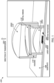
- FIG. 1 illustrates an embodiment of a monitored transmitter 100 comprising a reflective directing element 110 for a LiDAR system of the present teaching.
- the monitored transmitter 100 uses a 2D VCSEL array 102 for the laser source combined with a set of optics for projecting the laser beams along a direction of transmission 104.
- a monitor photodiode (MPD) 106 is shown mounted on the same substrate 108 as the VCSEL array 102.
- the monitor photodiode 106 or VCSEL 102 could also be mounted on separate carriers, or in separate packages.
- the monitor photodiode 106 and the VCSEL array 102 are nominally positioned in the same plane.
- the monitor photodiode 106 and the VCSEL array 102 have the normal projections to their respective surfaces having the same orientation. In some embodiments, this orientation is the same orientation as the direction of transmission 104.
- a directing element 110 which is located between a first lens 112 and a second lens 114, directs a portion of optical beams generated by the VCSEL array 102 back to the monitor photodiode 106. In some embodiments, the directing element 110 comprises a partial mirror located between a first lens 112 and a second lens 114 that reflects a portion of optical beams generated by the VCSEL array 102 back to the monitor photodiode 106.
- the first lens 112, second lens 114, and directing element 110 can be mounted in or on a common housing 116 that is secured to substrate 108.
- the direction of transmission in some embodiments is along the optical axis of the first lens 112 and/or the second lens 114.
- the monitored transmitter 100 is described using lenses 112, 114 to project the light in the optical beams generated by the VCSEL array 102.
- numerous other projecting optical elements can also be used.
- Numerous known implementations of projecting elements can be used in the monitored transmitter 100 of the present teaching.
- these projecting elements serve to shape and project the optical beams toward a target to achieve, for example, a desired field-of-view, target range, resolution, etc.
- These projecting elements can be configured to produce a common point for the optical beams within the transmitter footprint that allows the directing element to generate an illumination region at the monitor plane such that light from each of the optical beams can be monitored.
- some embodiments of the present teaching do not require all of the generated optical beams from the VCSEL array 102 to appear in the illumination region. Instead, in some embodiments, only a subset of the optical beams that share the common point for the optical beams are provided in the illumination region and sampled by the monitor. The relative positions of the projecting elements, VCSEL array 102 and directing element serve to determine a desired subset of optical beams that share the common point and therefore are provided in the illumination region.
- the directing element 110 of the monitored transmitter 100 embodiment of FIG. 1 is illustrated as being inclined towards the monitor photodiode 106. In other embodiments, the reflective mirror is not inclined towards the photodiode. Instead, the directing element 110 orientation might be such that the normal to the surface of the directing element 110 is parallel to an optical axis of the lens system in order to maintain rotational symmetry. This orientation can be advantageous in some cases for ease of assembly/manufacturing. Also, the directing element 110 is shown in FIG. 1 as a separate optical element, but it should be understood that in some embodiments, one or more of the surfaces of one or more of the two lenses 112, 114 or some other optical elements in the transmitter path, can function to provide the required reflection or direction.
- the optical components including one or more of the first lens 112, second lens 114, and directing element 110 have an optical coating on a surface that is designed to control reflectance.
- the optical reflectance is often set as low as possible to maximize the output power from the transmitter 100 in the direction of transmission 104.
- an optical coating on the directing element 110 might have a reflectance of up to 5%.
- the directing element 110 is not a separate discrete element but instead is an optical coating or set of coatings on one or more of the optical lens surfaces, where the reflectance of the coating has been selected to optimize the measured optical signal.
- a feature of the present teaching is that the directing element 110 can be placed within the path of the optical beams being generated by the laser at a common point so that every laser within the transmitter array has some portion of light that can be reflected. See, for example, U.S. Patent No. 10,514,444 , which describes a LiDAR transmitter that includes multiple lenses to achieve a small angular divergence of the transmitted optical beam.
- the directing element 110 is a diffractive optic element. In other embodiments, the directing element 110 is both a partially reflective mirror and an optical filter which blocks a portion of the visible spectrum. In one specific embodiments, the directing element is a prism. In some embodiments, the directing element is a holographic element. Numerous known lens configurations can be utilized to achieve the desired lens power, size and relative positions of the first lens 112 and second lens 114 and laser array 102.
- the monitor photodiode 106 is manufactured monolithically with the VCSEL array 102.
- the monitor photodiode 106 can be fabricated in numerous configurations.
- the monitor photodiode 106 is a single photodiode, which receives light from all the individual lasers within the 2D array.
- more than one photodiode is used where the outputs of the multiple photodiodes are combined in some fashion to provide a common signal output at some point in the signal chain.
- the monitor photodiode 106 includes an optical element positioned so that an input receives the light propagating from the monitor photodiode 106.
- the monitor photodiode 106 can include a light guide or a prism positioned to receive light and configured to direct that collected light to a photodiode.
- the optical element can take all the light in the monitoring aperture, or only a portion of the light from different spatial regions of the monitoring aperture, and then direct that light to one or more photodiodes.
- the optical element may be a lightpipe as described herein.
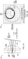
- FIG. 2A illustrates an expanded view 200 with additional detail of a portion of the monitored transmitter 100 for a LiDAR system of FIG. 1 .
- FIG. 2A shows an optical ray trace diagram 202 illustrating light emitted from the VCSEL array 102 that passes through lens 1 112, and then reflects off the partially reflective mirror 110 back towards the monitor photodiode 106 and VCSEL array 102.
- the monitor photodiode 106 is shown as photodiode positioned in the same plane 204 as the VCSEL array 102.
- the optical beams illustrated in the ray trace diagram 202 are shown as they pass to the directing element 110 where they are redirected to propagate to the second lens (not shown) and then out of the LiDAR transmitter 100 in the direction of transmission 104.
- FIG. 2B illustrates a cross-sectional view 250 of the optical ray trace 202 shown in FIG. 2A .
- the cross-sectional view 250 shows the illuminated area 256 encompassing the reflections off of the directing element 110 from different lasers within the VCSEL array 102.
- the illuminated area 256 of each beam is illustrated mapped over the area 252 of the monitor photodiode 106 and the area 254 of the VCELS array 102. This is because the directing element 110 projects light from a common point of the optical beams generated by the VCSEL, so the illumination region 256 includes at least some light from all the beams.
- the location of the directing element 110 and the incline angle of the mirror are chosen, so that no matter the location of a particular VCSEL element within the VCSEL array 102, the reflected areas all overlap in the proximity of the monitor photodiode 106. This ensures that the emitted power from every laser within the VCSEL array 102 can be monitored.
- the monitor photodiode 106 location is often constrained by other electronic components within the LiDAR system.
- the monitor photodiode 106 it is not possible to place the monitor photodiode 106 immediately adjacent to the VCSEL array 102. Instead, for easier manufacturing the monitor photodiode 106 may need to be some distance away from the VCSEL array 102, yet still close enough that it falls within the illuminated area of the reflected optical beams. Thus, the inclination and position of the directing element 110 must be properly chosen such that light from multiple elements in the array 102 overlaps at the monitor photodiode 106.
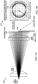
- FIG. 3A illustrates a portion 300 of an embodiment of a monitored transmitter comprising a monitor having a lightpipe 304 for a LiDAR system of the present teaching.
- the embodiments shown in FIG. 2A and FIG. 3A share many features.
- a VCSEL array 302 and monitor photodiode 304 are positioned in a same plane 306.
- a first lens 308 directs light beams from the array 302 toward a directing element 310, which may be a partially reflecting mirror, and then to a second lens (not shown) and out the transmitter along a direction of transmission 312.
- FIG. 3A shows an optical ray trace diagram 305 illustrating light emitted from the VCSEL array 302 that passes through lens 1 308, and then reflects off the partially reflective mirror 310 back towards the lightpipe 304 and the VCSEL array 302.
- FIG. 3B illustrates a cross-sectional view 350 of the optical ray trace 202 shown in FIG. 3A .
- the cross-sectional view 350 shows the illuminated area 352 encompassing the reflections off of the directing element 310 from different lasers within the VCSEL array 302.
- the illuminated area 352 of each beam is illustrated mapped over the area 354 of the monitor area that includes the collection area of a lightpipe 358 and the area 356 of the VCELS array footprint.
- This lightpipe 358 is shown connected to a remotely located monitor photodiode 360.
- the illuminated area 352 includes light from each of the optical beams generated by the VCSEL array 302 because the directing element 310 directs light from a common point of the optical beams generated by the VCSEL array 302 to the monitor 304 located at the monitor plane.
- the monitor 304 includes the lightpipe 358.
- a lightpipe is a device that acts as a waveguide that retains the light internally through total internal reflection as the light propagates along the length of the lightpipe.
- the lightpipe 358 can be made of glass or plastic, or can be a hollow waveguide with internal mirrored surfaces. Typically, the dimensions of the cross-section of the lightpipe 358 perpendicular to the axis of propagation are much smaller than the propagation distance.
- the lightpipe 358 can be constructed with fixed or flexible bends to direct the light as desired provided that the bend radius is sufficiently large to maintain total internal reflection.
- a common example of a lightpipe is a fiber optic cable.
- the lightpipe 358 is used to capture the light and provide the collected light to a photodiode (not shown).
- the lightpipe 358 captures a portion of the light from the illuminated area and redirects it to a monitor photodiode (not shown) that is physically distant from the VCSEL array 302 and also outside the illuminated area.
- Embodiments of the monitored transmitter that use a lightpipe do have an additional component, which can increase cost.
- the lightpipe might incorporate various optical elements including lenses, and mirrors.
- lightpipe embodiments have several potential advantages compared to other embodiments that do not use a lightpipe.
- One advantage of a lightpipe is that the size of the monitor photodiode for the active area is often restricted in physical size, which limits the optical signal that can be produced. Particularly, if the actual pulse shape, that is often nanoseconds in duration, needs to be measured, the photodiode active area should be small to have good dynamic response.
- a lightpipe can be designed with a larger collection area that allows measured light to be condensed/focused onto a smaller photodiode active area, thereby improving the SNR. Because the lightpipe is purely a passive optic component, it can be positioned on top of elements which may be physically close to the VCSEL array 302, such as the electrical drive components. Closer placement of the lightpipe to the VCSEL can also improve the optical efficiency of the monitoring function.
- Another potential advantage of using a lightpipe is the ability to locate the monitor photodiode relatively far from the VCSEL array and the VCSEL drive circuits. This feature is important because the drive currents/voltages used to operate the VCSEL can electrically couple and be a source of noise within the optical monitor circuit when the monitor diode is placed physically close to those components. It is highly desirable for the noise level be kept as low as possible in the optical monitor circuit in order to provide high SNR and any false readings.
- FIG. 4A shows a portion 400 of an embodiment of monitored transmitter comprising a transmissive directing element 410 for a LiDAR system of the present teaching.
- a VCSEL array 402 generates a plurality of optical beams that are directed to a first and second lens 404, 406. In this embodiment, the light is not reflected back towards the VCSEL array 402. The light impinges on a directing element 410, which in this embodiment is a transmissive element that is a mounting plate. In this configuration, the directing element 410 transmits, or passes, the light at the common point of passage of the optical beams toward the monitor 408.
- the monitor 408 is a microprism.
- the directing element 410 resides at a position with a common point of passage of the optical beams generated by the laser array that defines an illumination region that contains light from each laser. As such, the directing element 410 passes light from each of the optical beams being generated by the laser so that every laser within the VCSEL array 402 has some portion of light provided at an illumination region so that the light can be sampled by the monitor 408 placed within the illumination region. A small portion of the transmitted light in the illumination region is reflected by the monitor 408 in a direction largely perpendicular to the optical axis of the transmitter using a small micro-prism, which can be a diffractive optical element.
- the micro-prism of the monitor 408 is shown attached to the directing element 410, which is a mounting plate that in some embodiments is a transparent optical window, and in other embodiments is an optical filter.
- the directing element 410 is an optical element in the LiDAR transmitter that would be required even without the monitor 408.
- the directing element 410 provides two functions, one of which is securing the micro-prism of the monitor 408 and the other is optical in nature.
- the directing element 410 protects the LiDAR system from the outside environment.
- the micro-prism in the monitor 410 is shown coupling the light into an optical fiber 412 that has a core that is large enough to maintain the required optical signal level. The optical fiber 412 then directs the light to a monitor photodiode (not shown in the diagram).
- FIG. 4B illustrates a cross-sectional view 450 of the optical ray trace shown in FIG. 4A .
- the cross-sectional view 450 shows the illumination region 452 encompassing the illumination from all of the different lasers within the VCSEL array 402 at the plane of the directing element 410.
- the illumination region 452 that includes light from each beam is illustrated mapped over the collection area 454 of the sample prism area.
- the directing element 410 is placed within the path of the optical beams being generated by the laser at a common point so that every laser within the transmitter array has some portion of light that can be sampled by the monitor 408 that includes a microprism.
- the embodiment of a monitored transmitter with sampling prism shown in FIG. 4A has some advantages.
- One feature of this embodiment is that by removing the reflecting plate from within the lens system, the manufacturing and assembly of that lens system is simplified, and rotational symmetry of the lens system is maintained.
- the embodiment of a monitored transmitter with optical fiber 412 shown in FIG. 4A also has some advantages.
- One feature of this embodiment is that the fiber 412 allows the monitor photodiode to be placed physically distant from the VCSEL array 402 and the VCSEL drive circuitry.
- the monitor photodiode is not even on the same circuit board as the VCSEL array 402 drive circuitry. This configuration largely eliminates the possibility of the VCSEL array 402 drive circuit resulting in any unwanted noise or spurious signals being present in the optical monitor signal.
- Eliminating the physical constraints associated with the monitor photodiode being on a common circuit board with the VCSEL array 402 also enables the size and type of optical monitor to be very flexible, which can be advantageous for many reasons including reducing the size and/or complexity of the transmitter or the manufacturing process.
- the common point where the light is directed to from the illumination region can be positioned at various points in the optical transmitter.
- the common point can be determined by the positions of the projecting elements and the laser device.
- the common point can be positioned before the last optical lens surface in the transmitter optical system.
- the common point can be positioned after the last optical lens surface in the transmitter optical system.
- the optical monitor can be attached to an optical window which is the last optical element in the transmitter path and protects the LiDAR system from the outside environment.
- the optical monitor can be attached to one of the optical lens surfaces.
- the optical monitor can be attached to an optical filter element which blocks some portion of the visible spectrum.
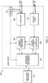
- FIG. 5 illustrates a block diagram of an embodiment of a LiDAR system 500 that includes a monitored transmitter according to the present teaching.
- the LiDAR system 500 has six main components: (1) controller and interface electronics 502; (2) transmit electronics including the laser driver 504; (3) the laser array 506; (4) receive and time-of-flight computation electronics 508; (5) detector array 510; and the (6) monitor 512.
- the controller and interface electronics 502 controls the overall function of the LiDAR system 500 and provides the digital communication to the host system processor 514.
- the transmit electronics 504 controls the operation of the laser array 506 and, in some embodiments, sets the pattern and/or power of laser firing of individual elements in the array 506.
- the receive and time-of-flight computation electronics 508 receives the electrical detection signals from the detector array 510 and then processes these electrical detection signals to compute the range distance through time-of-flight calculations.
- the monitor 512 is connected to one or both of the controller and interface electronics 502 and the transmit electronics including laser driver 504.
- the monitor 512 provides information on the detected signal power, and in combination with processing in one or both of the controller and interface electronics 502 and the transmit electronics including laser driver 504, provides information about laser wavelength, optical power, pulse timing, pulse frequency, and/or pulse duration among other parameters.
- the controller and interface electronics 502 directly controls and gets information from the monitor 512.
- the embodiment of FIG. 5 shows a partial mirror 516 directing light to the monitor 512.
- the LiDAR system 500 can operate with any of the configuration of the monitor 512 described herein and known variations of these configurations.
- the lasers in the array 506 are operated in closed loop configuration using one or both of the controller and interface electronics 502 and the transmit electronics including laser driver 504 that respond to a received photodiode current from a monitor photodiode that serves as an input to a bias control loop.
- This configuration can allow the transmitter optical power including the power from some or all of the optical beams generated by the laser array 506 to be maintained at a near constant value. This allows the system to be more stable against temperature and/or mechanical shifts.
- control loop via one or both of the controller and interface electronics 502 and transmit electronics including laser driver 504 that includes monitoring of the optical power and control of the laser bias can accommodate some amount of degradation of the laser efficiency over its lifetime, without loss of optical power at output of the LiDAR system 500.
- the controller and interface electronics 502 calculates an object reflectivity using an optical power reading generated by the monitor 512.
- the monitored optical power can be used as a reference and then, based on actual photon counting/intensity and pre-calibration, improved reflectivity data can be achieved.
- This improved reflectivity data can be utilized in systems that are used for various known LiDAR applications that relate to perception.
- a control loop via the controller and interface electronics 502 and/or the transmit electronics including laser driver 504, including the power monitor 512 can be used to indicate that the LiDAR transmitter is faulting, for example if the measured optical power is below or above a certain threshold.
- a control loop using one or both of the controller and interface electronics 502 and transmit electronics including laser driver 504 and including the power monitor 512 can be used to indicate the LiDAR transmitter is operating beyond an eye safety threshold if optical power is above a certain threshold.
- the monitored transmitter for a LiDAR system of the present teaching has been described in connection with various embodiments that use a single VCSEL array. It should be understood that the present teaching can be extended to LiDAR transmitters that include more than one VCSEL array. In these embodiments including more than one VCSEL array, the VCSEL arrays are positioned such that the illumination region that covers the monitor has a distinct region for each VCSEL array. In these embodiments, the monitor photodiode can be configured such that it includes more than one photodiode and a separate monitor photodiode can be used for each of the separate illumination regions.
Landscapes
- Engineering & Computer Science (AREA)
- Physics & Mathematics (AREA)
- General Physics & Mathematics (AREA)
- Radar, Positioning & Navigation (AREA)
- Remote Sensing (AREA)
- Computer Networks & Wireless Communication (AREA)
- Electromagnetism (AREA)
- Optics & Photonics (AREA)
- Condensed Matter Physics & Semiconductors (AREA)
- Optical Radar Systems And Details Thereof (AREA)
- Aviation & Aerospace Engineering (AREA)
- Automation & Control Theory (AREA)
Claims (15)
- Émetteur de détection de lumière et de télémétrie (100) avec une surveillance de puissance optique, l'émetteur (100) comprenant :a) un réseau laser (102 ; 302 ; 402 ; 506) positionné dans un premier plan (204 ; 306), le réseau laser (102 ; 302 ; 402 ; 506) étant configuré pour générer une pluralité de faisceaux optiques qui se propagent le long d'un trajet optique en réponse à un signal électrique fourni au niveau d'une entrée ;b) un premier élément optique de projection (112 ; 308 ; 404) positionné dans le trajet optique qui est configuré pour projeter la pluralité de faisceaux optiques de telle sorte que la pluralité de faisceaux optiques se chevauchent au moins partiellement en un point commun ;c) un second élément optique de projection (114 ; 406) positionné dans le trajet optique de la pluralité de faisceaux optiques après le premier élément optique de projection (112 ; 308 ; 404), et configuré pour projeter de la lumière provenant du premier élément optique de projection (112; 308 ; 404) dans une direction de transmission ;d) un élément optique directeur (110 ; 310 ; 410) positionné au niveau du point commun dans le trajet optique de la pluralité de faisceaux, l'élément optique directeur (110 ; 310 ; 410) étant configuré pour produire une région d'éclairage (256 ; 352 ; 452) comprenant au moins une partie de la lumière provenant de chaque faisceau de la pluralité de faisceaux dans un second plan (204 ; 306) ;e) un moniteur (106; 304 ; 408 ; 512) positionné dans la région d'éclairage (256 ; 352 ; 452) dans le second plan (204 ; 306) qui est configuré pour collecter au moins une partie de la lumière provenant de chaque faisceau de la pluralité de faisceaux, le moniteur (106 ; 304 ; 408 ; 512) comprenant une photodiode qui est configurée pour générer un signal détecté au niveau d'une sortie en réponse à la lumière collectée ; etf) un dispositif de commande (502) avec une entrée raccordée à une sortie du moniteur (106 ; 304 ; 408 ; 512) et une sortie raccordée à l'entrée du réseau laser (102 ; 302 ; 402 ; 506), le dispositif de commande (502) étant configuré pour générer le signal électrique en réponse au signal détecté qui commande le laser pour obtenir un fonctionnement souhaité de l'émetteur du système de détection de lumière et de télémétrie (100).
- Émetteur de détection de lumière et de télémétrie (100) selon la revendication 1, dans lequel le réseau laser (102 ; 302 ; 402 ; 506) comprend un réseau VCSEL et/ou dans lequel le réseau laser (102 ; 302 ; 402; 506) comprend un réseau bidimensionnel, dans lequel au moins deux lasers au sein du réseau peuvent être actionnés indépendamment.
- Émetteur de détection de lumière et de télémétrie (100) selon la revendication 1 ou 2, dans lequel les premier et second plans (204; 306) sont coplanaires ou sont positionnés au niveau de plans différents.
- Émetteur de détection de lumière et de télémétrie (100) selon une quelconque revendication précédente, dans lequel l'élément optique directeur (110 ; 310 ; 410) et le second élément optique de projection (114 ; 406) sont un même élément optique.
- Émetteur de détection de lumière et de télémétrie (100) selon une quelconque revendication précédente, dans lequel l'élément optique directeur (110 ; 310 ; 410) comprend un élément partiellement réfléchissant, un élément diffractif, un prisme, un élément holographique et/ou un élément optique plat.
- Émetteur de détection de lumière et de télémétrie (100) selon une quelconque revendication précédente, dans lequel l'élément optique directeur (110 ; 310 ; 410) est à la fois un miroir partiellement réfléchissant et un filtre optique et/ou dans lequel l'élément optique directeur (110 ; 310 ; 410) est un élément transmissif.
- Émetteur de détection de lumière et de télémétrie (100) selon une quelconque revendication précédente, dans lequel l'élément optique directeur (110 ; 310 ; 410) comprend un revêtement optique sur le second élément optique de projection (114 ; 406).
- Émetteur de détection de lumière et de télémétrie (100) selon une quelconque revendication précédente, dans lequel l'obtention du fonctionnement souhaité de l'émetteur de système de détection de lumière et de télémétrie (100) comprend l'obtention d'une mesure de performance prédéterminée, la sécurité des yeux et/ou la sécurité fonctionnelle.
- Émetteur de détection de lumière et de télémétrie (100) selon une quelconque revendication précédente, dans lequel le moniteur (106 ; 304 ; 408 ; 512) comprend une photodiode, un prisme d'échantillonnage et/ou un moniteur à plusieurs longueurs d'onde qui est configuré pour fournir des informations de longueur d'onde concernant la lumière collectée.
- Émetteur de détection de lumière et de télémétrie (100) selon une quelconque revendication précédente, dans lequel le moniteur (106; 304 ; 408 ; 512) comprend un guide de lumière (304 ; 358) couplé optiquement à une photodiode (360), facultativement dans lequel le guide de lumière (304 ; 358) est positionné sur un même substrat que le réseau laser (102 ; 302 ; 402 ; 506).
- Procédé de détection de lumière et de télémétrie avec une surveillance de puissance optique, le procédé comprenant :a) la génération d'une pluralité de faisceaux optiques dans un premier plan (204 ; 306) qui se propagent le long d'un trajet optique ;b) la projection de la pluralité de faisceaux optiques de telle sorte que la pluralité de faisceaux optiques se chevauchent au moins partiellement en un point commun ;c) le fait de diriger de la lumière à partir du point commun, ce qui permet de produire une région d'éclairage (256 ; 352 ; 452) comprenant au moins une partie de la lumière provenant de chaque faisceau de la pluralité de faisceaux dans un second plan (204 ; 306) ;d) la collecte d'au moins une partie de la lumière au niveau du second plan (204 ; 306) provenant de chaque faisceau de la pluralité de faisceaux, et la génération d'un signal détecté en réponse à la lumière collectée ; ete) la génération d'un signal électrique en réponse au signal détecté qui commande la génération de la pluralité de faisceaux optiques pour obtenir un fonctionnement souhaité de l'émetteur de système de détection de lumière et de télémétrie (100).
- Procédé selon la revendication 11, dans lequel les premier et second plans (204 ; 306) sont coplanaires ou sont positionnés au niveau de plans différents.
- Procédé selon la revendication 11 ou 12, dans lequel le fait de diriger de la lumière à partir du point commun comprend la diffraction de la lumière, la réflexion et le filtrage de la lumière et/ou la transmission de la lumière.
- Procédé selon l'une quelconque des revendications 11 à 13, dans lequel l'obtention du fonctionnement souhaité de l'émetteur de système de détection de lumière et de télémétrie (100) comprend l'obtention d'une mesure de performance prédéterminée, des conditions de fonctionnement sans danger pour les yeux et/ou la sécurité fonctionnelle.
- Procédé selon l'une quelconque des revendications 11 à 14, dans lequel la génération du signal électrique en réponse au signal détecté comprend la génération d'informations à plusieurs longueurs d'onde concernant la lumière collectée.
Applications Claiming Priority (2)
| Application Number | Priority Date | Filing Date | Title |
|---|---|---|---|
| US202063112735P | 2020-11-12 | 2020-11-12 | |
| PCT/US2021/058687 WO2022103778A1 (fr) | 2020-11-12 | 2021-11-10 | Système lidar à contrôleur de puissance optique d'émission |
Publications (3)
| Publication Number | Publication Date |
|---|---|
| EP4244653A1 EP4244653A1 (fr) | 2023-09-20 |
| EP4244653A4 EP4244653A4 (fr) | 2024-09-18 |
| EP4244653B1 true EP4244653B1 (fr) | 2025-06-18 |
Family
ID=81454333
Family Applications (1)
| Application Number | Title | Priority Date | Filing Date |
|---|---|---|---|
| EP21892689.7A Active EP4244653B1 (fr) | 2020-11-12 | 2021-11-10 | Système lidar à contrôleur de puissance optique d'émission |
Country Status (6)
| Country | Link |
|---|---|
| US (1) | US20220146680A1 (fr) |
| EP (1) | EP4244653B1 (fr) |
| JP (1) | JP2023549774A (fr) |
| KR (1) | KR20230126704A (fr) |
| CN (1) | CN116710801A (fr) |
| WO (1) | WO2022103778A1 (fr) |
Families Citing this family (17)
| Publication number | Priority date | Publication date | Assignee | Title |
|---|---|---|---|---|
| US10761195B2 (en) | 2016-04-22 | 2020-09-01 | OPSYS Tech Ltd. | Multi-wavelength LIDAR system |
| KR102592139B1 (ko) | 2017-03-13 | 2023-10-23 | 옵시스 테크 엘티디 | 눈-안전 스캐닝 lidar 시스템 |
| KR102326508B1 (ko) | 2017-07-28 | 2021-11-17 | 옵시스 테크 엘티디 | 작은 각도 발산을 갖는 vcsel 어레이 lidar 송신기 |
| KR102634870B1 (ko) | 2017-11-15 | 2024-02-13 | 옵시스 테크 엘티디 | 잡음 적응형 솔리드-스테이트 lidar 시스템 |
| DE102017127922A1 (de) * | 2017-11-27 | 2019-05-29 | Valeo Schalter Und Sensoren Gmbh | Optoelektronische Detektionseinrichtung, Verfahren zum Betrieb einer solchen Detektionseinrichtung und Kraftfahrzeug mit einer solchen Detektionseinrichtung |
| US11906663B2 (en) | 2018-04-01 | 2024-02-20 | OPSYS Tech Ltd. | Noise adaptive solid-state LIDAR system |
| WO2020028173A1 (fr) | 2018-08-03 | 2020-02-06 | OPSYS Tech Ltd. | Système lidar modulaire distribué à semi-conducteurs |
| WO2020210176A1 (fr) | 2019-04-09 | 2020-10-15 | OPSYS Tech Ltd. | Émetteur lidar à semi-conducteurs avec commande laser |
| EP3977159A4 (fr) | 2019-05-30 | 2023-03-01 | Opsys Tech Ltd. | Système lidar à longue portée sans danger pour les yeux utilisant un actionneur |
| KR102580722B1 (ko) | 2019-06-10 | 2023-09-22 | 옵시스 테크 엘티디 | 눈-안전 장거리 고체 상태 lidar 시스템 |
| KR102895523B1 (ko) | 2019-06-25 | 2025-12-05 | 옵시스 테크 엘티디 | 적응형 다중 펄스 lidar 시스템 |
| EP4004587A4 (fr) | 2019-07-31 | 2023-08-16 | Opsys Tech Ltd. | Émetteur lidar à semi-conducteurs à haute résolution |
| US12306299B2 (en) * | 2021-01-22 | 2025-05-20 | GM Global Technology Operations LLC | LIDAR laser health diagnostic |
| JP2023140131A (ja) * | 2022-03-22 | 2023-10-04 | 富士フイルムビジネスイノベーション株式会社 | 照射装置及び距離測定装置 |
| CN114993517A (zh) * | 2022-05-20 | 2022-09-02 | 深圳泰德激光技术股份有限公司 | 激光光路检测方法、系统、终端设备及介质 |
| US20250306177A1 (en) * | 2024-03-26 | 2025-10-02 | OPSYS Tech Ltd. | LiDAR Transmitter with Flat Optics |
| KR20250156333A (ko) * | 2024-04-25 | 2025-11-03 | 다믈파워반도체 유한회사 | Vcsel 드라이버 고장 검출 장치 |
Family Cites Families (17)
| Publication number | Priority date | Publication date | Assignee | Title |
|---|---|---|---|---|
| DE3536659A1 (de) | 1984-12-27 | 1986-07-03 | Impulsphysik Gmbh, 2000 Hamburg | Vorrichtung zur wolkenhoehenmessung |
| GB0317630D0 (en) * | 2003-07-28 | 2003-08-27 | Qinetiq Ltd | Optical transmitter and receiver apparatus |
| US7440084B2 (en) * | 2004-12-16 | 2008-10-21 | Arete' Associates | Micromechanical and related lidar apparatus and method, and fast light-routing components |
| US7253386B2 (en) * | 2005-12-12 | 2007-08-07 | Xerox Corporation | Method and apparatus for monitoring and controlling laser intensity in a ROS scanning system |
| US7963447B2 (en) * | 2007-11-30 | 2011-06-21 | Symbol Technologies, Inc. | Enhanced monitoring of laser output power in electro-optical readers |
| US20090273770A1 (en) * | 2008-04-30 | 2009-11-05 | Honeywell International Inc. | Systems and methods for safe laser imaging, detection and ranging (lidar) operation |
| US9069059B2 (en) * | 2010-05-13 | 2015-06-30 | Laser Lions LLC | Concealed light detection and ranging system |
| US20130208256A1 (en) * | 2012-02-10 | 2013-08-15 | Optical Air Data Systems, Llc. | LDV with Diffractive Optical Element for Transceiver Lens |
| CN104505708A (zh) * | 2014-12-16 | 2015-04-08 | 昂纳信息技术(深圳)有限公司 | 一种垂直腔面发射激光器组件 |
| US10063849B2 (en) * | 2015-09-24 | 2018-08-28 | Ouster, Inc. | Optical system for collecting distance information within a field |
| US10557940B2 (en) * | 2015-11-30 | 2020-02-11 | Luminar Technologies, Inc. | Lidar system |
| US10761195B2 (en) * | 2016-04-22 | 2020-09-01 | OPSYS Tech Ltd. | Multi-wavelength LIDAR system |
| JP2018005183A (ja) * | 2016-07-08 | 2018-01-11 | 株式会社リコー | 光走査装置、物体検知装置および距離検知装置 |
| US10408940B2 (en) * | 2016-09-25 | 2019-09-10 | James Thomas O'Keeffe | Remote lidar with coherent fiber optic image bundle |
| DE102016118189B4 (de) * | 2016-09-27 | 2018-08-30 | Trumpf Werkzeugmaschinen Gmbh + Co. Kg | Verfahren und Laserbearbeitungsmaschine zum Laserschweißen eines ersten und eines zweiten Werkstückabschnitts |
| US12007504B2 (en) * | 2019-03-01 | 2024-06-11 | Vixar, Inc. | 3D and LiDAR sensing modules |
| EP4155763A4 (fr) * | 2020-05-22 | 2024-09-11 | SOS Lab Co., Ltd. | Dispositif lidar |
-
2021
- 2021-11-10 KR KR1020237016314A patent/KR20230126704A/ko active Pending
- 2021-11-10 US US17/522,953 patent/US20220146680A1/en active Pending
- 2021-11-10 WO PCT/US2021/058687 patent/WO2022103778A1/fr not_active Ceased
- 2021-11-10 JP JP2023528055A patent/JP2023549774A/ja active Pending
- 2021-11-10 EP EP21892689.7A patent/EP4244653B1/fr active Active
- 2021-11-10 CN CN202180079908.4A patent/CN116710801A/zh active Pending
Also Published As
| Publication number | Publication date |
|---|---|
| EP4244653A4 (fr) | 2024-09-18 |
| JP2023549774A (ja) | 2023-11-29 |
| KR20230126704A (ko) | 2023-08-30 |
| WO2022103778A1 (fr) | 2022-05-19 |
| EP4244653A1 (fr) | 2023-09-20 |
| CN116710801A (zh) | 2023-09-05 |
| US20220146680A1 (en) | 2022-05-12 |
Similar Documents
| Publication | Publication Date | Title |
|---|---|---|
| EP4244653B1 (fr) | Système lidar à contrôleur de puissance optique d'émission | |
| US12298399B2 (en) | Receive path for LiDAR system | |
| US11808887B2 (en) | Methods and systems for mapping retroreflectors | |
| CN112068150B (zh) | 激光雷达和测距方法 | |
| CN109613515B (zh) | 一种激光雷达系统 | |
| EP3430428B1 (fr) | Éclairage et détection intégrés pour imagerie 3d basée sur lidar | |
| JP7542658B2 (ja) | レーザレーダ及び測距方法 | |
| CN113646661B (zh) | 用于实时lidar距离校准的系统和方法 | |
| US20220120899A1 (en) | Ranging device and mobile platform | |
| CN108761427B (zh) | 分布式激光雷达及自动驾驶系统 | |
| CN113030911A (zh) | 一种激光雷达系统 | |
| KR102711191B1 (ko) | 복수의 갈바노미터 스캐너를 적용한 광시야 라이더 및 차량 | |
| CN115685154A (zh) | 激光雷达的调整方法及其系统、激光雷达 | |
| CN115480253A (zh) | 一种基于spad线阵探测器的三维扫描激光雷达 | |
| CN210894689U (zh) | 一种激光发射装置以及激光雷达系统 | |
| CN113960619A (zh) | 一种片上集成测距芯片 | |
| CN222618775U (zh) | 一种高精度的激光雷达光路装置 | |
| CN221056668U (zh) | 测距装置及测距系统 | |
| CN118244238B (zh) | Mems振镜激光雷达系统及电子设备 | |
| CN222887720U (zh) | 一种光接收装置和激光雷达 | |
| CN219871762U (zh) | 同轴激光雷达和终端设备 | |
| CN220085058U (zh) | 光纤式激光雷达和激光雷达系统 | |
| US20250189635A1 (en) | Light source module including an optical path and a method of operating the light source module | |
| US20230184906A1 (en) | Integrated tx/rx and scanner module | |
| CN120577787A (zh) | 一种激光雷达装置 |
Legal Events
| Date | Code | Title | Description |
|---|---|---|---|
| STAA | Information on the status of an ep patent application or granted ep patent |
Free format text: STATUS: THE INTERNATIONAL PUBLICATION HAS BEEN MADE |
|
| PUAI | Public reference made under article 153(3) epc to a published international application that has entered the european phase |
Free format text: ORIGINAL CODE: 0009012 |
|
| STAA | Information on the status of an ep patent application or granted ep patent |
Free format text: STATUS: REQUEST FOR EXAMINATION WAS MADE |
|
| 17P | Request for examination filed |
Effective date: 20230612 |
|
| AK | Designated contracting states |
Kind code of ref document: A1 Designated state(s): AL AT BE BG CH CY CZ DE DK EE ES FI FR GB GR HR HU IE IS IT LI LT LU LV MC MK MT NL NO PL PT RO RS SE SI SK SM TR |
|
| DAV | Request for validation of the european patent (deleted) | ||
| DAX | Request for extension of the european patent (deleted) | ||
| A4 | Supplementary search report drawn up and despatched |
Effective date: 20240816 |
|
| RIC1 | Information provided on ipc code assigned before grant |
Ipc: G01S 7/4912 20200101ALI20240809BHEP Ipc: G01S 7/486 20200101ALI20240809BHEP Ipc: G02B 7/02 20210101ALI20240809BHEP Ipc: G02B 5/04 20060101ALI20240809BHEP Ipc: H01S 5/42 20060101ALI20240809BHEP Ipc: G01S 7/481 20060101ALI20240809BHEP Ipc: G01S 7/484 20060101ALI20240809BHEP Ipc: G01S 7/4863 20200101ALI20240809BHEP Ipc: G01S 7/497 20060101AFI20240809BHEP |
|
| GRAP | Despatch of communication of intention to grant a patent |
Free format text: ORIGINAL CODE: EPIDOSNIGR1 |
|
| STAA | Information on the status of an ep patent application or granted ep patent |
Free format text: STATUS: GRANT OF PATENT IS INTENDED |
|
| INTG | Intention to grant announced |
Effective date: 20250205 |
|
| GRAS | Grant fee paid |
Free format text: ORIGINAL CODE: EPIDOSNIGR3 |
|
| GRAA | (expected) grant |
Free format text: ORIGINAL CODE: 0009210 |
|
| STAA | Information on the status of an ep patent application or granted ep patent |
Free format text: STATUS: THE PATENT HAS BEEN GRANTED |
|
| AK | Designated contracting states |
Kind code of ref document: B1 Designated state(s): AL AT BE BG CH CY CZ DE DK EE ES FI FR GB GR HR HU IE IS IT LI LT LU LV MC MK MT NL NO PL PT RO RS SE SI SK SM TR |
|
| REG | Reference to a national code |
Ref country code: GB Ref legal event code: FG4D |
|
| REG | Reference to a national code |
Ref country code: CH Ref legal event code: EP |
|
| REG | Reference to a national code |
Ref country code: DE Ref legal event code: R096 Ref document number: 602021032618 Country of ref document: DE |
|
| REG | Reference to a national code |
Ref country code: CH Ref legal event code: EP |
|
| REG | Reference to a national code |
Ref country code: IE Ref legal event code: FG4D |
|
| PG25 | Lapsed in a contracting state [announced via postgrant information from national office to epo] |
Ref country code: FI Free format text: LAPSE BECAUSE OF FAILURE TO SUBMIT A TRANSLATION OF THE DESCRIPTION OR TO PAY THE FEE WITHIN THE PRESCRIBED TIME-LIMIT Effective date: 20250618 |
|
| REG | Reference to a national code |
Ref country code: LT Ref legal event code: MG9D |
|
| PG25 | Lapsed in a contracting state [announced via postgrant information from national office to epo] |
Ref country code: GR Free format text: LAPSE BECAUSE OF FAILURE TO SUBMIT A TRANSLATION OF THE DESCRIPTION OR TO PAY THE FEE WITHIN THE PRESCRIBED TIME-LIMIT Effective date: 20250919 Ref country code: NO Free format text: LAPSE BECAUSE OF FAILURE TO SUBMIT A TRANSLATION OF THE DESCRIPTION OR TO PAY THE FEE WITHIN THE PRESCRIBED TIME-LIMIT Effective date: 20250918 |
|
| PG25 | Lapsed in a contracting state [announced via postgrant information from national office to epo] |
Ref country code: BG Free format text: LAPSE BECAUSE OF FAILURE TO SUBMIT A TRANSLATION OF THE DESCRIPTION OR TO PAY THE FEE WITHIN THE PRESCRIBED TIME-LIMIT Effective date: 20250618 |
|
| PG25 | Lapsed in a contracting state [announced via postgrant information from national office to epo] |
Ref country code: HR Free format text: LAPSE BECAUSE OF FAILURE TO SUBMIT A TRANSLATION OF THE DESCRIPTION OR TO PAY THE FEE WITHIN THE PRESCRIBED TIME-LIMIT Effective date: 20250618 |
|
| PG25 | Lapsed in a contracting state [announced via postgrant information from national office to epo] |
Ref country code: RS Free format text: LAPSE BECAUSE OF FAILURE TO SUBMIT A TRANSLATION OF THE DESCRIPTION OR TO PAY THE FEE WITHIN THE PRESCRIBED TIME-LIMIT Effective date: 20250918 |
|
| REG | Reference to a national code |
Ref country code: NL Ref legal event code: MP Effective date: 20250618 |
|
| PG25 | Lapsed in a contracting state [announced via postgrant information from national office to epo] |
Ref country code: LV Free format text: LAPSE BECAUSE OF FAILURE TO SUBMIT A TRANSLATION OF THE DESCRIPTION OR TO PAY THE FEE WITHIN THE PRESCRIBED TIME-LIMIT Effective date: 20250618 |
|
| PG25 | Lapsed in a contracting state [announced via postgrant information from national office to epo] |
Ref country code: NL Free format text: LAPSE BECAUSE OF FAILURE TO SUBMIT A TRANSLATION OF THE DESCRIPTION OR TO PAY THE FEE WITHIN THE PRESCRIBED TIME-LIMIT Effective date: 20250618 |
|
| PG25 | Lapsed in a contracting state [announced via postgrant information from national office to epo] |
Ref country code: PT Free format text: LAPSE BECAUSE OF FAILURE TO SUBMIT A TRANSLATION OF THE DESCRIPTION OR TO PAY THE FEE WITHIN THE PRESCRIBED TIME-LIMIT Effective date: 20251020 |
|
| REG | Reference to a national code |
Ref country code: AT Ref legal event code: MK05 Ref document number: 1804669 Country of ref document: AT Kind code of ref document: T Effective date: 20250618 |