EP4244516B1 - Sanitärarmatur - Google Patents
Sanitärarmatur Download PDFInfo
- Publication number
- EP4244516B1 EP4244516B1 EP21892421.5A EP21892421A EP4244516B1 EP 4244516 B1 EP4244516 B1 EP 4244516B1 EP 21892421 A EP21892421 A EP 21892421A EP 4244516 B1 EP4244516 B1 EP 4244516B1
- Authority
- EP
- European Patent Office
- Prior art keywords
- plumbing
- fitting
- tab
- cap
- engagement
- Prior art date
- Legal status (The legal status is an assumption and is not a legal conclusion. Google has not performed a legal analysis and makes no representation as to the accuracy of the status listed.)
- Active
Links
Images


Classifications
-
- F—MECHANICAL ENGINEERING; LIGHTING; HEATING; WEAPONS; BLASTING
- F16—ENGINEERING ELEMENTS AND UNITS; GENERAL MEASURES FOR PRODUCING AND MAINTAINING EFFECTIVE FUNCTIONING OF MACHINES OR INSTALLATIONS; THERMAL INSULATION IN GENERAL
- F16L—PIPES; JOINTS OR FITTINGS FOR PIPES; SUPPORTS FOR PIPES, CABLES OR PROTECTIVE TUBING; MEANS FOR THERMAL INSULATION IN GENERAL
- F16L35/00—Special arrangements used in connection with end fittings of hoses, e.g. safety or protecting devices
-
- F—MECHANICAL ENGINEERING; LIGHTING; HEATING; WEAPONS; BLASTING
- F16—ENGINEERING ELEMENTS AND UNITS; GENERAL MEASURES FOR PRODUCING AND MAINTAINING EFFECTIVE FUNCTIONING OF MACHINES OR INSTALLATIONS; THERMAL INSULATION IN GENERAL
- F16L—PIPES; JOINTS OR FITTINGS FOR PIPES; SUPPORTS FOR PIPES, CABLES OR PROTECTIVE TUBING; MEANS FOR THERMAL INSULATION IN GENERAL
- F16L37/00—Couplings of the quick-acting type
- F16L37/08—Couplings of the quick-acting type in which the connection between abutting or axially overlapping ends is maintained by locking members
- F16L37/12—Couplings of the quick-acting type in which the connection between abutting or axially overlapping ends is maintained by locking members using hooks, pawls, or other movable or insertable locking members
- F16L37/1225—Couplings of the quick-acting type in which the connection between abutting or axially overlapping ends is maintained by locking members using hooks, pawls, or other movable or insertable locking members using a retaining member the extremities of which, e.g. in the form of a U, engage behind a shoulder of both parts
-
- F—MECHANICAL ENGINEERING; LIGHTING; HEATING; WEAPONS; BLASTING
- F16—ENGINEERING ELEMENTS AND UNITS; GENERAL MEASURES FOR PRODUCING AND MAINTAINING EFFECTIVE FUNCTIONING OF MACHINES OR INSTALLATIONS; THERMAL INSULATION IN GENERAL
- F16L—PIPES; JOINTS OR FITTINGS FOR PIPES; SUPPORTS FOR PIPES, CABLES OR PROTECTIVE TUBING; MEANS FOR THERMAL INSULATION IN GENERAL
- F16L37/00—Couplings of the quick-acting type
- F16L37/08—Couplings of the quick-acting type in which the connection between abutting or axially overlapping ends is maintained by locking members
- F16L37/084—Couplings of the quick-acting type in which the connection between abutting or axially overlapping ends is maintained by locking members combined with automatic locking
- F16L37/098—Couplings of the quick-acting type in which the connection between abutting or axially overlapping ends is maintained by locking members combined with automatic locking by means of flexible hooks
- F16L37/0985—Couplings of the quick-acting type in which the connection between abutting or axially overlapping ends is maintained by locking members combined with automatic locking by means of flexible hooks the flexible hook extending radially inwardly from an outer part and engaging a bead, recess or the like on an inner part
-
- F—MECHANICAL ENGINEERING; LIGHTING; HEATING; WEAPONS; BLASTING
- F16—ENGINEERING ELEMENTS AND UNITS; GENERAL MEASURES FOR PRODUCING AND MAINTAINING EFFECTIVE FUNCTIONING OF MACHINES OR INSTALLATIONS; THERMAL INSULATION IN GENERAL
- F16L—PIPES; JOINTS OR FITTINGS FOR PIPES; SUPPORTS FOR PIPES, CABLES OR PROTECTIVE TUBING; MEANS FOR THERMAL INSULATION IN GENERAL
- F16L37/00—Couplings of the quick-acting type
- F16L37/08—Couplings of the quick-acting type in which the connection between abutting or axially overlapping ends is maintained by locking members
- F16L37/084—Couplings of the quick-acting type in which the connection between abutting or axially overlapping ends is maintained by locking members combined with automatic locking
- F16L37/098—Couplings of the quick-acting type in which the connection between abutting or axially overlapping ends is maintained by locking members combined with automatic locking by means of flexible hooks
-
- F—MECHANICAL ENGINEERING; LIGHTING; HEATING; WEAPONS; BLASTING
- F16—ENGINEERING ELEMENTS AND UNITS; GENERAL MEASURES FOR PRODUCING AND MAINTAINING EFFECTIVE FUNCTIONING OF MACHINES OR INSTALLATIONS; THERMAL INSULATION IN GENERAL
- F16L—PIPES; JOINTS OR FITTINGS FOR PIPES; SUPPORTS FOR PIPES, CABLES OR PROTECTIVE TUBING; MEANS FOR THERMAL INSULATION IN GENERAL
- F16L37/00—Couplings of the quick-acting type
- F16L37/08—Couplings of the quick-acting type in which the connection between abutting or axially overlapping ends is maintained by locking members
- F16L37/12—Couplings of the quick-acting type in which the connection between abutting or axially overlapping ends is maintained by locking members using hooks, pawls, or other movable or insertable locking members
- F16L37/133—Couplings of the quick-acting type in which the connection between abutting or axially overlapping ends is maintained by locking members using hooks, pawls, or other movable or insertable locking members using flexible hooks
-
- F—MECHANICAL ENGINEERING; LIGHTING; HEATING; WEAPONS; BLASTING
- F16—ENGINEERING ELEMENTS AND UNITS; GENERAL MEASURES FOR PRODUCING AND MAINTAINING EFFECTIVE FUNCTIONING OF MACHINES OR INSTALLATIONS; THERMAL INSULATION IN GENERAL
- F16L—PIPES; JOINTS OR FITTINGS FOR PIPES; SUPPORTS FOR PIPES, CABLES OR PROTECTIVE TUBING; MEANS FOR THERMAL INSULATION IN GENERAL
- F16L33/00—Arrangements for connecting hoses to rigid members; Rigid hose-connectors, i.e. single members engaging both hoses
- F16L33/22—Arrangements for connecting hoses to rigid members; Rigid hose-connectors, i.e. single members engaging both hoses with means not mentioned in the preceding groups for gripping the hose between inner and outer parts
- F16L33/225—Arrangements for connecting hoses to rigid members; Rigid hose-connectors, i.e. single members engaging both hoses with means not mentioned in the preceding groups for gripping the hose between inner and outer parts a sleeve being movable axially
-
- F—MECHANICAL ENGINEERING; LIGHTING; HEATING; WEAPONS; BLASTING
- F16—ENGINEERING ELEMENTS AND UNITS; GENERAL MEASURES FOR PRODUCING AND MAINTAINING EFFECTIVE FUNCTIONING OF MACHINES OR INSTALLATIONS; THERMAL INSULATION IN GENERAL
- F16L—PIPES; JOINTS OR FITTINGS FOR PIPES; SUPPORTS FOR PIPES, CABLES OR PROTECTIVE TUBING; MEANS FOR THERMAL INSULATION IN GENERAL
- F16L37/00—Couplings of the quick-acting type
- F16L37/08—Couplings of the quick-acting type in which the connection between abutting or axially overlapping ends is maintained by locking members
- F16L37/084—Couplings of the quick-acting type in which the connection between abutting or axially overlapping ends is maintained by locking members combined with automatic locking
- F16L37/091—Couplings of the quick-acting type in which the connection between abutting or axially overlapping ends is maintained by locking members combined with automatic locking by means of a ring provided with teeth or fingers
-
- F—MECHANICAL ENGINEERING; LIGHTING; HEATING; WEAPONS; BLASTING
- F16—ENGINEERING ELEMENTS AND UNITS; GENERAL MEASURES FOR PRODUCING AND MAINTAINING EFFECTIVE FUNCTIONING OF MACHINES OR INSTALLATIONS; THERMAL INSULATION IN GENERAL
- F16L—PIPES; JOINTS OR FITTINGS FOR PIPES; SUPPORTS FOR PIPES, CABLES OR PROTECTIVE TUBING; MEANS FOR THERMAL INSULATION IN GENERAL
- F16L37/00—Couplings of the quick-acting type
- F16L37/08—Couplings of the quick-acting type in which the connection between abutting or axially overlapping ends is maintained by locking members
- F16L37/084—Couplings of the quick-acting type in which the connection between abutting or axially overlapping ends is maintained by locking members combined with automatic locking
- F16L37/092—Couplings of the quick-acting type in which the connection between abutting or axially overlapping ends is maintained by locking members combined with automatic locking by means of elements wedged between the pipe and the frusto-conical surface of the body of the connector
- F16L37/0926—Couplings of the quick-acting type in which the connection between abutting or axially overlapping ends is maintained by locking members combined with automatic locking by means of elements wedged between the pipe and the frusto-conical surface of the body of the connector with an inner support sleeve arranged within the pipe
-
- F—MECHANICAL ENGINEERING; LIGHTING; HEATING; WEAPONS; BLASTING
- F16—ENGINEERING ELEMENTS AND UNITS; GENERAL MEASURES FOR PRODUCING AND MAINTAINING EFFECTIVE FUNCTIONING OF MACHINES OR INSTALLATIONS; THERMAL INSULATION IN GENERAL
- F16L—PIPES; JOINTS OR FITTINGS FOR PIPES; SUPPORTS FOR PIPES, CABLES OR PROTECTIVE TUBING; MEANS FOR THERMAL INSULATION IN GENERAL
- F16L37/00—Couplings of the quick-acting type
- F16L37/08—Couplings of the quick-acting type in which the connection between abutting or axially overlapping ends is maintained by locking members
- F16L37/084—Couplings of the quick-acting type in which the connection between abutting or axially overlapping ends is maintained by locking members combined with automatic locking
- F16L37/092—Couplings of the quick-acting type in which the connection between abutting or axially overlapping ends is maintained by locking members combined with automatic locking by means of elements wedged between the pipe and the frusto-conical surface of the body of the connector
- F16L37/0927—Couplings of the quick-acting type in which the connection between abutting or axially overlapping ends is maintained by locking members combined with automatic locking by means of elements wedged between the pipe and the frusto-conical surface of the body of the connector the wedge element being axially displaceable for releasing the coupling
-
- F—MECHANICAL ENGINEERING; LIGHTING; HEATING; WEAPONS; BLASTING
- F16—ENGINEERING ELEMENTS AND UNITS; GENERAL MEASURES FOR PRODUCING AND MAINTAINING EFFECTIVE FUNCTIONING OF MACHINES OR INSTALLATIONS; THERMAL INSULATION IN GENERAL
- F16L—PIPES; JOINTS OR FITTINGS FOR PIPES; SUPPORTS FOR PIPES, CABLES OR PROTECTIVE TUBING; MEANS FOR THERMAL INSULATION IN GENERAL
- F16L37/00—Couplings of the quick-acting type
- F16L37/08—Couplings of the quick-acting type in which the connection between abutting or axially overlapping ends is maintained by locking members
- F16L37/12—Couplings of the quick-acting type in which the connection between abutting or axially overlapping ends is maintained by locking members using hooks, pawls, or other movable or insertable locking members
- F16L37/138—Couplings of the quick-acting type in which the connection between abutting or axially overlapping ends is maintained by locking members using hooks, pawls, or other movable or insertable locking members using an axially movable sleeve
Definitions
- This invention relates to a plumbing fitting.
- Plumbing fittings are used to connect plumbing lines to one another or to other plumbing components and the like. Some plumbing fittings incorporate a releasable mechanism that allows a user to disconnect the fitting from a plumbing line or component. Other fittings may incorporate mechanisms which allow the fitting itself to be disassembled, or require the fitting itself to be disassembled to allow a connected plumbing line or component to be disconnected from the fitting.
- these mechanisms often require complex assemblies with many moving parts. Further, these mechanisms may allow one to tamper with the fitting or connected components, making the fitting and connected components susceptible to damage or theft.
- WO2020/135553A1 discloses a quick connector, the quick connector comprising a sleeve joint part and a sliding lock.
- the sleeve joint part comprises a stop part, and the stop part is configured to stop the automatic moving of the sliding lock toward the interior of the sleeve joint part in the transverse direction in the period when a fluid pipeline is inserted into the sleeve joint part, and release the stopping of the sliding black when the pipeline is completely pushed into the main body of the sleeve joint part.
- GB2500061A discloses a connector for connecting respiratory ducts together such that they are placed in fluid communication, the connector comprising, a first conduit having a female connector end; and a second conduit having a male connector end adapted to be received within the female connector end of the first conduit, wherein the male connector has a retaining formation which is adapted to abut a corresponding formation on the female connector so as to resist separation.
- the fitting end comprises a spacer receiving section configured to receive the spacer members so as to permit the free end of each of the tabs to displace radially inwardly thereby bringing together the inner circumferential surface of the tabs with the outer circumferential surface of the fitting end.
- each receiver and respective engagement projection are together configured to substantially inhibit longitudinal translation and/or axial rotation of the cap relative to the body when the receiver receives the respective engagement projection.
- the spacer receiving section and the spacer members are together configured to substantially inhibit longitudinal translation and/or axial rotation of the cap relative to the body when the spacer members are received by the spacer receiving section.
- the body comprises at least one engagement ridge extending longitudinally along and radially outwardly from the outer circumferential surface of the fitting end and configured to engage between adjacent tabs.
- the at least one engagement ridge is configured to substantially inhibit axial rotation of the cap relative to the body when the at least one engagement ridge is engaged between the adjacent tabs.
- the at least one engagement ridge is configured to engage in a slot between the adjacent tabs.
- the first receiver and second receiver each comprise a receiver aperture extending through a radial thickness of the first and second tabs respectively.
- the spacer members are circumferentially offset from the first and second receivers.
- the slot is circumferentially offset from the first and second receivers.
- the body comprises: a third engagement projection and a fourth engagement projection circumferentially spaced apart from the first and second engagement projections and extending radially outwardly from the outer circumferential surface of the fitting end; and wherein the cap comprises: a third tab and a fourth tab each having a free end at the receiving end of the cap; the third tab comprising a third receiver that is configured to receive the third engagement projection and the fourth tab comprising a fourth receiver that is configured to receive the fourth engagement projection; wherein the third tab and the fourth tab each comprise a radially inwardly extending spacer member at the free end of the third tab and fourth tab respectively.
- the body comprises a bore extending from the fitting end and longitudinally through the body and configured to receive a plumbing assembly and wherein the cap comprises a plumbing aperture configured to receive a plumbing line couplable to the plumbing assembly.
- receipt of the of the plumbing line by the plumbing aperture, coupling of the plumbing line to the plumbing assembly, receipt of the plumbing assembly by the bore and coupling of the cap to the body together provide a substantially fluidly-sealed connection of the plumbing line to the plumbing fitting.
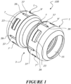
- Figure 1 shows an illustrative embodiment of a plumbing fitting 100 in its assembled state.
- the plumbing fitting 100 may be used to provide fluid communication between plumbing lines, or plumbing features and devices such as valves, tanks, control systems and the like.
- Reference to a 'plumbing application' or 'plumbing system' in this specification may encompass any system that conveys fluids, such as, for example, a domestic or commercial heating and cooling system, a domestic or commercial hot or cold water system, an industrial waste removal system, an automotive coolant system, and any other fluid conveying system conceivable by one skilled in the art.
- plumbing fitting 100 providing fluid communication may encompass fluid comprising any liquid, any liquid/gas mixture, any gas, or any substantially liquid mixture containing solid particulates or the like.
- the plumbing fitting 100 is shown with two caps 1 assembled on opposing ends of a single body 3. These opposing ends of the body 3 comprise fitting ends 5 to which the caps 1 can be coupled.
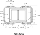
- this body 3 shown in figures 1-12 is only one example configuration of the body 3.
- the body 3 may instead comprise only one fitting end 5, with the other end of the body 3 forming part of a plumbing component such as a valve, or integrally formed with a wall or other structural feature through which a plumbing line 301 fitted to the plumbing fitting 100 passes.
- the body 3 may also instead comprise a tee-junction, or four-way junction, or any other suitable intermediate plumbing junction, having a plurality of fitting ends 5 for connecting a plurality of plumbing lines, as described in further detail below.
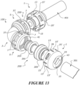
- the body may be substantially straight between the fitting ends 5 as shown in figures 1-12 , or alternatively could have one end angularly offset from the other end in an elbow configuration such as shown in figure 13 for example.
- pluming fitting will be described with reference to one cap 1 and one fitting end 5. It will be appreciated in at least some embodiments the plumbing fitting will have a plurality of the fitting ends 5 and caps 1, and like reference numbers indicate like parts.
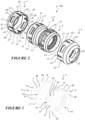
- FIGs 2 and 13 show the plumbing fittings 100 in a disassembled state.
- the plumbing fitting 100 comprises a cap 1 and a body 3.
- the body 3 comprises a fitting end 5 that is configured to be received by the cap 1.
- the body also comprises a first engagement projection 7 and a second engagement projection 9 (not visible in figure 2 , but shown in figure 3 ) that are circumferentially spaced apart from each other, and that extend radially outwardly from an outer circumferential surface 11 of the fitting end 5.
- the cap 1 comprises a first tab 13 and a second tab 15, each tab respectively having a free end 17, 19 at a receiving end 21 of the cap 1.
- the receiving end 21 of the cap 1 is substantially open so as to receive the fitting end 5 of the body 3.
- the first tab 13 comprises a first receiver 23 that is configured to receive the first engagement projection 7 and the second tab 15 comprises a second receiver 25 that is configured to receive the second engagement projection 9.
- the body 3 shown in figures 1-13 also comprises third and fourth engagement projections 7', 9'
- the cap 1 shown in figures 1-13 also comprises third and fourth tabs 13', 15' with corresponding receivers 23', 25'.
- the third engagement projection 7' and fourth engagement projection 9' are circumferentially spaced apart from the first and second engagement projections 7, 9 and also extend radially outwardly from the outer circumferential surface 11 of the fitting end 5.
- the third tab and fourth tab 13', 15' each have a free end 17', 19' at the receiving end 21 of the cap 1, with the third tab 13' comprising a third receiver 23' that is configured to receive the third engagement projection 7' and the fourth tab 15' comprising a fourth receiver 25' that is configured to receive the fourth engagement projection 9'.
- the third tab 13' and the fourth tab 15' also each comprise a radially inwardly extending spacer member 27', 29' at the free end of the third tab 13' and fourth tab 15' respectively.
- the cap 1 may comprise anywhere from two to eight, or even more tabs 13, 13', 15, 15' and corresponding receivers 23, 23', 25, 25', and the body 3 may likewise comprises anywhere from two to eight, or even more, corresponding engagement projections 7, 7', 9, 9'.
- the body 3 may likewise comprises anywhere from two to eight, or even more, corresponding engagement projections 7, 7', 9, 9'.
- any description of the functions and features of the first and second engagement projections, tabs, receivers, or other components/features corresponding to or arranged thereon may apply equally to third, fourth, fifth etc. engagement projections, tabs, receivers, or other components/features corresponding to or arranged thereon, and the like.
- Like reference numbers indicate like parts with an addition of a prime (').
- figures 1-13 illustrate a 'four-tab' embodiment of the plumbing fitting 100, reference will be made predominately to the first and second of the respective engagement projections, tabs, receivers, and components/features corresponding to or arranged thereon in this specification.
- Figures 4 and 5 show detailed views of the cap 1.
- the first and second tabs 13, 15 are configured to permit flexure of each tab relative to the other.
- each tab 13, 15 of the cap 1 can move, flex, or deform relative to one another and relative to the substantially rigid cone end 2 of the cap 1.
- the free end 17 of the first tab 13 and the free end 19 of the second tab 15 can displace radially outwardly, and optionally radially inwardly, relative to their default circumferential positions shown in figures 1-13 .
- the features of the cap 1 that provide this functionality are described in further detail below.
- Each tab 13', 15' also has at least one radially inwardly extending spacer member 27', 29' at the free end 17', 19' of the tab 13', 15'.
- the variants for the spacer member(s) is/are as outlined in the preceding paragraph.
- the spacer members 27, 29 are configured such that, as the fitting end 5 is received by the cap 1, the free end 17, 19 of each of the tabs 13, 15 is displaced radially outwardly from their default circumferential positions shown in figures 1-13 .
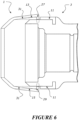
- the spacer members 27, 29 are configured as such so as to space apart an inner circumferential surface 31 of the tabs 13, 15 from the outer circumferential surface 11 of the fitting end 5, as the fitting end 5 is received by the cap 1. This provides clearance for travel of the receivers 23, 25 over the respective engagement projections 7, 9, due to the radially outward displacement as shown in figure 6 .
- the plumbing fitting 100 is thereby configured so that the dimensions of the cap 1 and body 3 and their respective features correspond to one another so as to require spacing apart of the inner circumferential surface 31 from the outer circumferential surface 11 to provide clearance for travel of the receivers 23, 25 over the respective engagement projections 7, 9.
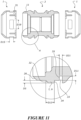
- FIGS 7-11 show cross sectional views of the body 3
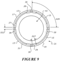
- figure 9 shows a rear view of the cap 1
- figures 10 and 11 show cross sectional views of the plumbing fitting 100 in its disassembled state.
- the plumbing fitting 100 is dimensioned such that the diameter D1 of the outer circumferential surface 11 of the fitting end 5 is substantially equal to the diameter D3 of the inner circumferential surface 31 of the tabs 13, 15.
- receipt of the fitting end 5 by the cap 1 represents a tight-interference fit in which substantial force is required to press the fitting end 5 of the body 3 into the receiving end 21 of the cap 1.
- Such a fitment typically results in coupling of parts that is predominantly secured through friction between the surfaces of the parts.
- the resulting friction between the outer circumferential surface 11 of the fitting end 5 and the inner circumferential surface 31 of the tabs 13, 15 assists in preventing the cap 1 from being easily removable from the body 3 by simply pulling apart the two along the axial longitudinal direction of the plumbing fitting 100.
- the first receiver 23 and second receiver 25 each comprise a receiver aperture extending through the circumferential thickness D7 of the first and second tabs 13, 15 respectively.
- the circumferential thickness D7 is in a radial direction, so can alternatively be considered a radial thickness.
- the circumferential height D5 of each of the engagement projections 7, 9 is dimensioned to be substantially equal to, or greater than, the circumferential thickness D7 of the tabs 13, 15 (shown in figure 10 ).
- the tabs 13, 15 require clearance above this height D5 in order for the receivers 23, 25 to receive the projections 7, 9.
- the circumferential height D5 is in a radial direction, so can alternatively be considered a radial height.
- the receivers 23, 25 may instead comprise recesses extending radially outwardly from the inner circumferential surface 31 of the tabs 13, 15 into the thickness D7 of the tabs 13, 15, but not through the full circumferential thickness D7.
- the circumferential height D5 of each of the engagement projections 7, 9 will instead by dimensioned to be substantially equal to, but not greater than, the circumferential thickness D7 of the tabs 13, 15.
- the circumferential height D5 of each of the engagement projections 7, 9 may also be less than the circumferential thickness D7 of the tabs 13, 15.
- the circumferential depth D9 of the spacer members 27, 29 is configured to be substantially equal to, or greater than, the circumferential height D5 each of the engagement projections 7, 9, so as to permit sufficient outward radial displacement of the free ends 17, 19 of each of the tabs 13, 15.
- the circumferential depth D9 is in a radial direction, so can alternatively be considered a radial depth.
- the fitting end 5 comprises a spacer receiving section configured to receive the spacer members 27, 29 so as to permit the free end 17, 19 of each of the tabs 13, 15 to displace radially inwardly, from their radially outwardly displaced positions, thereby bringing together the inner circumferential surface 31 of the tabs 13, 15 with the outer circumferential surface 11 of the fitting end 5, once the cap 1 is fully inserted onto the fitting end 5.
- the spacer receiver section is dimensioned so as to correspond to the circumferential depth D9 of the spacer members 27, 29.
- This is shown in figures 10 and 11 , wherein the circumferential depth D11 of the substantially annular engagement channel 33 (shown in figure 11 ) is equal to, or greater than, the circumferential depth D9 (shown in figure 10 ) of the spacer members 27, 29.
- the receivers 23, 25 and the substantially annular engagement channel 33 are dimensioned appropriately with respect to the engagement projections 7, 9 and the spacer members 27, 29 to constrain and enclose them in a way that substantially inhibits movement of the cap 1 relative to the body 3, once the fitting end 5 is received by the cap 1.
- the length D13 (shown in figure 11 ) of the engagement projections 7, 9 is substantially equal to the length D15 (shown in figure 11 ) of the receivers 23, 25.
- the cap 1 is substantially inhibited from translation in the longitudinal direction, as both longitudinal ends of the engagement projections 7, 9 are constrained by respective longitudinal internal walls of the receivers 23, 25.
- each receiver 23, 25 and respective engagement projection 7, 9 are together configured to substantially inhibit longitudinal translation and/or axial rotation of the cap 1 relative to the body 3 when the receiver 23, 25 receives the respective engagement projection 7, 9.
- this particular embodiment of the plumbing fitting 100 comprises two spacer members at lateral ends of each tab, the outermost lateral wall of the outermost spacer members of each tab contacts a respective lateral wall of each engagement ridge 37, so as to substantially inhibit rotation about the longitudinal direction of the cap 1 relative to the body 3.
- the substantially annular engagement channel 33 may nonetheless possess inward lateral walls that constrain the spacer members of a given tab in the same manner as the engagement ridges 37.
- the body 3 comprises at least one engagement ridge 37 extending longitudinally along and radially outwardly from the outer circumferential surface 11 of the fitting end 5 and configured to engage between adjacent tabs.
- the at least one engagement ridge 37 is configured to engage in a slot 39 between the adjacent tabs.
- the at least one engagement ridge 37 is configured to engage between any two adjacent tabs (or a slot between any two adjacent tabs).
- the at least one engagement ridge 37 may engage with a discontinuous space between adjacent tabs, such as the slot 39, an internal recess between adjacent tabs (or the like), or a deformable section between adjacent tabs.
- the deformable section may comprise a portion of material that is more flexible than the material from which the tabs are formed, or may comprise a portion of material defining or enclosing the recess, made of the same or a more flexible material than the material from which the tabs are formed.
- the cap 1 may comprise a combination of slots, recesses or deformable sections or combinations/modifications thereof between adjacent tabs.
- the circumferential lengths of the tabs, and their circumferential positions can be configured so that the at least one engagement ridge 37 engages in a slot/recess/deformable section/or combinations/modifications thereof having any given circumferential length or thickness.
- the first and second tabs 13, 15 may have the same circumferential lengths and positions as the first and second tabs 13, 15 shown in the 'four-tab' embodiment of figures 1-13 , with spaces between the first and second tabs 13, 15 where the third and fourth tabs 13', 15' are shown; therefore, the at least one engagement ridge 37 would engage between the first and second tabs 13, 15 in either of those spaces (having similar circumferential lengths as the third and fourth tabs 13', 15'), and those spaces may comprise a slot/recess/deformable section/or combinations/modifications thereof.
- the circumferential lengths of the tabs are configured so as to extend substantially around the circumference of the cap 1, in a similar manner to the 'four-tab' embodiment of figures 1-13 .
- each tab is able to move, flex, or deform relative to one another and relative to the substantially rigid cone end 2 of the cap 1.
- the slot/recess/deformable section/or combinations/modifications thereof between adjacent tabs should extend from the receiving end 21 of the cap 1 into a substantial length of the cap 1, so as to permit enough flexibility for the free ends 17, 19 of the tabs to displace radially inwardly or outwardly relative to their default circumferential positions shown in figures 1-13 .
- the length of the slot/recess/deformable section/or combinations/modifications thereof between adjacent tabs thereby substantially defines the length of each tab.
- the slots 39, and the at least one engagement ridge 27 are dimensioned respectively so as to provide constrained enclosure of the engagement ridges 27 by the slots 39.
- the circumferential thickness D31 (shown in figure 8 ) of the at least one engagement ridge 27 is substantially equal to the circumferential thickness D33 (shown in figure 9 ) of the slot 39 between the adjacent tabs.
- the cap 1 is substantially inhibited from rotation about the longitudinal direction, as one of, or both lateral sides of at least one engagement ridge 27 is constrained by respective internal lateral walls of the slot 39 between the adjacent tabs.
- the at least one engagement ridge 27 is configured to substantially inhibit axial rotation of the cap 1 relative to the body 3 when the at least one engagement ridge 27 is engaged between the adjacent tabs (or engaged in a slot 39 between adjacent tabs).
- the positions of the various features of the cap 1 and body 3 correspond to one another so as to provide a coupling that may be easily and quickly aligned.
- the receivers 23, 25 are configured to receive the engagement projections 7, 9, the positions of the receivers 23, 25 appropriately correspond to the positions of the engagement projections 7, 9.
- the slots 29 are configured to receive the at least one engagement ridge 37, the positions of the engagement ridges 37 appropriately correspond to the positions of the slots 29.
- the spacer receiver section comprising the substantially annular engagement channel 33 is configured to receive the spacer members 27, 28, 29, 30, the positions of the discrete engagement channels 33 appropriately correspond to the positions of the spacer members 27, 28, 29, 30.
- the spacer members 27, 28, 29, 30 are circumferentially offset from the first and second receivers 23, 25. This ensures that the spacer members 27, 28, 29, 30 do not contact or abut against the engagement projections 7, 9 during receipt of the fitting end 5 by the cap 1.
- each tab need only comprise one spacer member, however if two or more spacer members are provided on a given tab, they must be arranged so as to be circumferentially offset from the receiver of that tab for the same reason.
- the slot 29 is circumferentially offset from the first and second receivers 23, 25. This ensures that the engagement ridges 37 do not contact the first and second receivers 23, 25 during receipt of the fitting end 5 by the cap 1.
- first and second engagement projections 7, 9, as well as the third and fourth (or fifth, sixth, seventh etc.) engagement projections are all circumferentially spaced apart from one another.
- the various features of the cap 1 and body 3 are shown correspondingly arranged about the circumferences of the cap 1 and body 3 to respectively interface with one another. Further, since the various features of the cap 1 are arranged on, or correspond to a given tab, the cap 1 can be axially rotated to align any one given tab having its various features, with any one given engagement projection and the features of the fitting end 5 proximal that engagement projection.
- tabs that are configured in a circumferentially symmetric manner.
- a user may easily rotate either the cap 1 or the body 3 about 90 degrees to align any one given tab of the cap 1 having its various features with any one given engagement projection of the body 3, to thereby and quickly and easily couple them together.
- the plumbing fitting 100 through provision of engagement projections 7, 9, receivers 23, 25, spacer members 27, 29, spacer receiver sections (substantially annular engagement channel 33) and optionally, engagement ridges 37 and slots 29 between each tab, provides a substantially non-releasable coupling of the cap 1 to the body 3. This in turn, prevents the plumbing fitting 100 from being easily disassembled, damaged or tampered with, providing security for the plumbing lines connected thereto, as well as features of the plumbing assembly 200 (described in further detail below) enclosed by the plumbing fitting 100.
- the cap 1 and its various features are preferably integrally formed from a uniform material, as is the body 3 and its various features. Therefore, the plumbing fitting 100 provides such a substantially non-releasable and tamper-proof coupling, without the need for complex assemblies with many moving parts.
- the material comprises a deformable material such as moulded plastic or the like.
- the material may comprise aluminium, aluminium alloy(s), brass, brass alloy(s), steel, stainless steel, steel alloy(s), or any other suitable metal or metal alloy(s).
- the provision of the features described above mean that the cap 1 is deformed elastically for a minimal period of time during use of the plumbing fitting 100.
- the tabs 13, 15 of the cap 1 substantially maintain their original integrity, rather than permanently or inelastically deforming the tabs 13, 15 and therefore weakening the coupling of the cap 1 to the body 3.
- the engagement projections 7, 9 and corresponding receivers 23, 25 are shown having substantially rectangular shapes, however they may instead take wedge-shape, concave shape or convex shape as outlined above, for example, as long as that shape still comprises the dimensions D13, D15, D17, D19 of the engagement projections 7, 9 and corresponding receivers 23, 25 described above, as well as features such as the inner ledge 34 of the engagement projections 7, 9 cooperating with internal walls of the receivers 23, 25, that causes engagement between the two to substantially inhibit longitudinal translation and/or axial rotation of the cap 1 relative to the body 3 when the receiver 23, 25 receives the respective engagement projection 7, 9.
- the plumbing assembly 200 is first arranged within the bore 41 of the body 3, then the plumbing line 301 run through the plumbing aperture 43 of the cap 1.
- the open end 303 of the plumbing line 301 is passed through the grab-edge member 205 and the O-ring 201 to press around and receive the cylindrical body of the insert 203, before the cap 1 is pushed onto the fitting end 5 of the body 3 so as to substantially non-releasably couple the cap 1 to the body 3, and therefore enclose the plumbing assembly 200 and the open end 303 of the plumbing line 301 within the plumbing fitting 100.
- the plumbing assembly 200 shown in figure 13 comprising the grab-edge member 205 allows one to disconnect the plumbing line 301 from the plumbing fitting 100 without requiring disassembly of the plumbing fitting 100 itself. This may be achieved by simply pushing the edge of the grab-edge member 205 that protrudes from the plumbing aperture 43 further into the interior of the plumbing fitting 100 while simultaneously pulling and twisting the plumbing 301 line out from the interior of the plumbing fitting 100, causing the grab-edge member 205 to release the open end 303 of the pluming line 301 from the insert 203 and thus allowing the plumbing line 301 to be pulled out from the plumbing aperture 43 of the cap 1.
- each of these other ends may comprise a fitting end configured in substantially the same manner as the fitting end 5 described throughout this specification, and therefore be configured to be received by a cap configured in substantially the same manner as the cap 1 described throughout this specification.
- the body 3 may be configured to provide connection between a plurality of plumbing lines, with each connection being substantially non-releasable and thereby protected from tamper, damage and/or theft.
- the other dimensions D1-D33 in this exemplary embodiment have the following values: D1 28.6mm, D3 28.6mm, D5 1.1mm, D7 1.1mm, D8 10.9mm, D10 11.8mm, D9 1.1mm, D11 2.0mm, D13 3.8mm, D15 4.3mm, D17 9.4mm, D19 10mm, D21 1.3mm, D23 1.1mm, D25 19.1mm, D29 18.6mm, D27 3mm, D31 1.6mm, D33 1.6mm.
- dimensions D8 and D10, D13 and D15, D17 and D19, D21 and D23, D25 and D29 are all described above as 'substantially equal', and as listed for the exemplary embodiment above, may have less than 1.0mm of difference between each corresponding pair.
- dimensions D1 and D3, D5 and D7, D31 and D33 have exact matching values. Differences between dimensions described as 'corresponding' or 'substantially equal' may be smaller or larger than those listed above.
- the largest maximum diameter D35 may range from about 10mm to about 110mm, or larger, with the other dimensions D1-D33 scaling up or down in proportion with D35.
Landscapes
- Engineering & Computer Science (AREA)
- General Engineering & Computer Science (AREA)
- Mechanical Engineering (AREA)
- Protection Of Pipes Against Damage, Friction, And Corrosion (AREA)
- Pipe Accessories (AREA)
- Quick-Acting Or Multi-Walled Pipe Joints (AREA)
Claims (15)
- Sanitäres Einbauteil (100), umfassend:eine Kappe (1) undeinen Körper (3), der ein Anschlussende (5) umfasst, das zur Aufnahme durch die Kappe (1) ausgestaltet ist, wobei der Körper (3) einen ersten Eingriffsvorsprung (7) und einen zweiten Eingriffsvorsprung (9) umfasst, die in Umfangsrichtung voneinander beabstandet sind und die sich von einer Außenumfangsfläche (11) des Anschlussendes (5) radial nach außen erstrecken,wobei die Kappe (1) Folgendes umfasst:eine erste Lasche (13) und eine zweite Lasche (15), wobei jede Lasche ein freies Ende (17, 19) an einem Aufnahmeende (21) der Kappe (1) aufweist,wobei die erste Lasche (13) einen ersten Aufnehmer (23) umfasst, der zur Aufnahme des ersten Eingriffsvorsprungs (7) ausgelegt ist, und die zweite Lasche (15) einen zweiten Aufnehmer (25) umfasst, der zur Aufnahme des zweiten Eingriffsvorsprungs (9) ausgelegt ist,wobei die Laschen (13, 15) dazu ausgelegt sind, eine Biegung jeder Lasche bezüglich einander zu gestatten, und wobei jede Lasche (13, 15) ein sich radial nach innen erstreckendes Abstandshalterglied (27, 29) an dem freien Ende (17, 19) der Lasche (13, 15) umfasst,wobei die Abstandshalterglieder (27, 29) so ausgestaltet sind, dass, wenn das Anschlussende (5) von der Kappe (1) aufgenommen wird, das freie Ende (17, 19) jeder der Laschen (13, 15) radial nach außen verschoben wird, um eine Innenumfangsfläche (31) der Laschen (13, 15) von der Außenumfangsfläche (11) des Anschlussendes (5) zu beabstanden, wodurch ein Freiraum für die Aufnahme der Eingriffsvorsprünge (7, 9) durch die Aufnehmer (23, 25) bereitgestellt wird.
- Sanitäres Einbauteil (100) nach Anspruch 1, wobei das Anschlussende (5) einen Abstandshalteraufnahmeabschnitt umfasst, der zur Aufnahme der Abstandshalterglieder (27, 29) ausgestaltet ist, damit sich das freie Ende (17, 19) jeder der Laschen (13, 15) radial nach innen verschieben kann, wodurch die Innenumfangsfläche (31) der Laschen (13, 15) mit der Außenumfangsfläche (11) des Anschlussendes (5) zusammengeführt wird.
- Sanitäres Einbauteil (100) nach Anspruch 2, wobei die Aufnahme der Eingriffsvorsprünge (7, 9) durch die Aufnehmer (23, 25) zusammen mit der Aufnahme der Abstandshalterglieder (27, 29) durch den Abstandshalteraufnahmeabschnitt zusammen eine im Wesentlichen nicht lösbare Kopplung der Kappe (1) an den Körper (3) bereitstellt.
- Sanitäres Einbauteil (100) nach einem der vorhergehenden Ansprüche, wobei jeder Aufnehmer (23, 25) und jeder jeweilige Eingriffsvorsprung (7, 9) zusammen dazu ausgestaltet sind, eine Längstranslation und/oder eine axiale Drehung der Kappe (1) bezüglich des Körpers (3) im Wesentlichen zu verhindern, wenn der Aufnehmer (23, 25) den jeweiligen Eingriffsvorsprung (7, 9) aufnimmt.
- Sanitäres Einbauteil (100) nach Anspruch 2 oder Anspruch 3 oder 4, wenn abhängig von Anspruch 2, wobei der Abstandshalteraufnahmeabschnitt und die Abstandshalterglieder (27, 29) zusammen dazu ausgestaltet sind, eine Längstranslation und/oder eine axiale Drehung der Kappe (1) bezüglich des Körpers (3) im Wesentlichen zu verhindern, wenn die Abstandshalterglieder (27, 29) von dem Abstandshalteraufnahmeabschnitt aufgenommen werden.
- Sanitäres Einbauteil (100) nach einem der vorhergehenden Ansprüche, wobei der Körper (3) mindestens eine Eingriffsrippe (37) umfasst, die sich in Längsrichtung entlang und radial nach außen von der Außenumfangsfläche (11) des Anschlussendes (5) erstreckt und zur Eingriffnahme zwischen benachbarten Laschen ausgelegt ist, und vorzugsweise
wobei die mindestens eine Eingriffsrippe (37) dazu ausgestaltet ist, eine axiale Drehung der Kappe (1) bezüglich des Körpers (3) im Wesentlichen zu verhindern, wenn die mindestens eine Eingriffsrippe (37) zwischen den benachbarten Laschen in Eingriff steht. - Sanitäres Einbauteil (100) nach einem der Ansprüche 3 bis 6, wenn abhängig von Anspruch 2, wobei der Abstandshalteraufnahmeabschnitt mindestens eine nach innen gerichtete Leiste umfasst, die sich von der Außenumfangsfläche (11) des Anschlussendes (5) radial nach innen erstreckt.
- Sanitäres Einbauteil (100) nach einem der Ansprüche 3 bis 6, wenn abhängig von Anspruch 2, wobei der Abstandshalteraufnahmeabschnitt einen im Wesentlichen ringförmigen Eingriffskanal (33) umfasst, der sich von der Außenumfangsfläche (11) des Anschlussendes (5) radial nach innen erstreckt.
- Sanitäres Einbauteil (100) nach Anspruch 6 oder nach Anspruch 7 oder 8, wenn abhängig von Anspruch 6, wobei die mindestens eine Eingriffsrippe (37) dazu ausgestaltet ist, in einem Schlitz (39) zwischen den benachbarten Laschen in Eingriff zu kommen.
- Sanitäres Einbauteil (100) nach einem der vorhergehenden Ansprüche, wobei der erste Aufnehmer (23) und der zweite Aufnehmer (25) jeweils eine Aufnehmeröffnung umfassen, die sich durch eine radiale Dicke (D7) der ersten bzw. zweiten Lasche (13, 15) erstreckt.
- Sanitäres Einbauteil (100) nach einem der vorhergehenden Ansprüche, wobei die Abstandshalterglieder (27, 29) in Umfangsrichtung von dem ersten und dem zweiten Aufnehmer (23, 25) versetzt sind.
- Sanitäres Einbauteil (100) nach Anspruch 11, wobei der Schlitz (39) in Umfangsrichtung von dem ersten und dem zweiten Aufnehmer (23, 25) versetzt ist.
- Sanitäres Einbauteil (100) nach einem der Ansprüche 1 bis 12, wobei der Körper (3) Folgendes umfasst:einen dritten Eingriffsvorsprung (7') und einen vierten Eingriffsvorsprung (9'), die in Umfangsrichtung von dem ersten und dem zweiten Eingriffsvorsprung (7, 9) beabstandet sind und sich von der Außenumfangsfläche (11) des Anschlussendes (5) radial nach außen erstrecken,und wobei die Kappe (1) Folgendes umfasst:eine dritte Lasche (13') und eine vierte Lasche (15'), die jeweils ein freies Ende (17', 19') an dem Aufnahmeende (21) der Kappe (1) aufweisen,wobei die dritte Lasche (13') einen dritten Aufnehmer (23') umfasst, der zur Aufnahme des dritten Eingriffsvorsprungs (7') ausgestaltet ist, und die vierte Lasche (15') einen vierten Aufnehmer (25') umfasst, der zur Aufnahme des vierten Eingriffsvorsprungs (9') ausgestaltet ist,wobei die dritte Lasche (13') und die vierte Lasche (15') jeweils ein sich radial nach innen erstreckendes Abstandshalterglied (27', 29') an dem freien Ende (17', 19') der dritten Lasche (13') bzw. der vierten Lasche (15') umfassen.
- Sanitäres Einbauteil (100) nach einem der vorhergehenden Ansprüche, wobei der Körper (3) eine Bohrung (41) umfasst, die sich von dem Anschlussende (5) und in Längsrichtung durch den Körper (3) erstreckt und zur Aufnahme einer Sanitärbaugruppe (200) ausgestaltet ist, und wobei die Kappe (1) eine Sanitäröffnung (43) umfasst, die dazu ausgestaltet ist, eine Sanitärleitung (301) aufzunehmen, die an die Sanitärbaugruppe (200) koppelbar ist.
- Sanitäres Einbauteil nach Anspruch 14, wenn abhängig von Anspruch 3, wobei die Aufnahme der Sanitärleitung (301) durch die Sanitäröffnung (43), die Kopplung der Sanitärleitung (301) an die Sanitärbaugruppe (200), die Aufnahme der Sanitärbaugruppe (200) durch die Bohrung (41) und die Kopplung der Kappe (1) an den Körper (3) zusammen eine im Wesentlichen fluidisch abgedichtete Verbindung der Sanitärleitung (301) mit dem sanitären Einbauteil (100) bereitstellen.
Applications Claiming Priority (2)
| Application Number | Priority Date | Filing Date | Title |
|---|---|---|---|
| NZ76985620 | 2020-11-11 | ||
| PCT/NZ2021/050187 WO2022103277A1 (en) | 2020-11-11 | 2021-10-22 | Plumbing fitting |
Publications (4)
| Publication Number | Publication Date |
|---|---|
| EP4244516A1 EP4244516A1 (de) | 2023-09-20 |
| EP4244516A4 EP4244516A4 (de) | 2024-03-20 |
| EP4244516C0 EP4244516C0 (de) | 2025-03-12 |
| EP4244516B1 true EP4244516B1 (de) | 2025-03-12 |
Family
ID=81601534
Family Applications (1)
| Application Number | Title | Priority Date | Filing Date |
|---|---|---|---|
| EP21892421.5A Active EP4244516B1 (de) | 2020-11-11 | 2021-10-22 | Sanitärarmatur |
Country Status (5)
| Country | Link |
|---|---|
| US (1) | US12215813B2 (de) |
| EP (1) | EP4244516B1 (de) |
| CN (1) | CN115702305A (de) |
| CA (1) | CA3200861A1 (de) |
| WO (1) | WO2022103277A1 (de) |
Families Citing this family (2)
| Publication number | Priority date | Publication date | Assignee | Title |
|---|---|---|---|---|
| IT202200013153A1 (it) * | 2022-06-22 | 2023-12-22 | Hutchinson S R L | Elemento di raffreddamento per un componente elettrico, in particolare per una batteria elettrica di un veicolo elettrico o ibrido. |
| CN115585323A (zh) * | 2022-10-21 | 2023-01-10 | 广汽埃安新能源汽车股份有限公司 | 一种液冷部件连接件、液冷系统以及电池装配方法 |
Family Cites Families (15)
| Publication number | Priority date | Publication date | Assignee | Title |
|---|---|---|---|---|
| CA2032830C (en) * | 1990-12-20 | 1994-07-26 | Robert Graham Straghan | Coupling |
| FR2807815B1 (fr) | 2000-04-12 | 2002-06-21 | Comap | Dispositif de raccordement demontable pour tuyau |
| FR2863683B1 (fr) * | 2003-12-10 | 2006-02-17 | Legris Sa | Dispositif de raccordement instantane |
| FR2881811B1 (fr) * | 2005-02-10 | 2007-04-20 | Legris Sa | Dispositif de raccordement instantane avec moyen de verrouillage et/ou de deconnexion |
| JP4937236B2 (ja) | 2008-11-26 | 2012-05-23 | 株式会社ニフコ | 燃料タンク用コネクタ、及び逆止弁 |
| GB2500061B (en) * | 2012-03-09 | 2018-11-28 | Intersurgical Ag | Connector for respiratory ducts |
| AU2014366835B2 (en) | 2013-12-19 | 2019-10-31 | Reliance Worldwide Corporation (Aust.) Pty. Ltd. | Pipe connection fitting |
| DE102014107530A1 (de) * | 2014-05-28 | 2015-12-03 | Voss Automotive Gmbh | "Aufnahmeteil für eine Fluid-Steckkupplung und Fluid-Steckkupplung mit einem derartigen Aufnahmeteil" |
| DE102014211844A1 (de) * | 2014-06-20 | 2015-12-24 | Contitech Mgw Gmbh | Kupplungselement zur flexiblen Verbindung zweier Elemente zur Führung von Medien |
| GB2549510B (en) * | 2016-04-20 | 2021-03-17 | John Guest International Ltd | A Connector |
| GB2570296B (en) | 2018-01-17 | 2021-02-10 | John Guest International Ltd | A connector |
| GB2573165B (en) * | 2018-04-27 | 2020-11-18 | John Guest International Ltd | A connector |
| EP3904746B1 (de) * | 2018-12-29 | 2024-04-17 | A. Raymond et Cie SCS | Schnellverbinder |
| CN109737260A (zh) * | 2018-12-29 | 2019-05-10 | 瑞肯耐特流体控制系统(镇江)有限公司 | 快速连接器 |
| DE102019216782A1 (de) * | 2019-10-30 | 2021-05-06 | Contitech Mgw Gmbh | Fluidleitungskupplung |
-
2021
- 2021-10-22 CN CN202180045115.0A patent/CN115702305A/zh active Pending
- 2021-10-22 WO PCT/NZ2021/050187 patent/WO2022103277A1/en not_active Ceased
- 2021-10-22 US US18/252,407 patent/US12215813B2/en active Active
- 2021-10-22 CA CA3200861A patent/CA3200861A1/en active Pending
- 2021-10-22 EP EP21892421.5A patent/EP4244516B1/de active Active
Also Published As
| Publication number | Publication date |
|---|---|
| WO2022103277A1 (en) | 2022-05-19 |
| US12215813B2 (en) | 2025-02-04 |
| EP4244516C0 (de) | 2025-03-12 |
| CA3200861A1 (en) | 2022-05-19 |
| EP4244516A4 (de) | 2024-03-20 |
| EP4244516A1 (de) | 2023-09-20 |
| US20230400134A1 (en) | 2023-12-14 |
| CN115702305A (zh) | 2023-02-14 |
Similar Documents
| Publication | Publication Date | Title |
|---|---|---|
| EP4244516B1 (de) | Sanitärarmatur | |
| EP1933074B1 (de) | Verbesserungen bei oder in Zusammenhang mit Rohrkopplungen | |
| EP2220417B1 (de) | Vorrichtung zur verbindung von zwei starren objekten | |
| EP1185811B1 (de) | Ableitventil mit durchlaufmöglichkeit | |
| CA2720485A1 (en) | Mechanical pipe fitting device assembly | |
| EP2466159A1 (de) | Befestigungsanordnung | |
| CA2897002C (en) | Quick connect coupling with a self-resetting retention mechanism | |
| WO2000003886A2 (en) | Quick connector with secondary latch confirming feature | |
| EP1178255A2 (de) | Rohrverbindung | |
| EP3320247A1 (de) | Leitungshaltende struktur für leitungsendstück | |
| NZ575593A (en) | A connector system using a locking mechanism on the male part that engages the threads of the female part | |
| EP2213923B1 (de) | Drehverbindungsstelle | |
| WO2004031636A1 (en) | Mechanical tube to fitting connection | |
| EP1714068B1 (de) | Verbinder mit freigabemechanismus | |
| US20200173819A1 (en) | Quick connect sensor assembly | |
| EP1872044B1 (de) | Rohrverbindungsvorrichtung | |
| ES3018913T3 (en) | Plumbing fitting | |
| EP3728926B1 (de) | Verbinder für schaltungselemente | |
| CA3104805A1 (en) | System, method and apparatus for debris shield for squeeze-activated retainer for a conduit | |
| JP2023547914A (ja) | 流体接続アセンブリ | |
| US20210247005A1 (en) | Ferrule assembly for conduit fitting | |
| EP3155306B1 (de) | Anpassbares verbindungsteil | |
| EP1724511A2 (de) | Schnellverbinder mit Halteelement | |
| CA2232856A1 (en) | Quick connector with confirmation feature |
Legal Events
| Date | Code | Title | Description |
|---|---|---|---|
| STAA | Information on the status of an ep patent application or granted ep patent |
Free format text: STATUS: THE INTERNATIONAL PUBLICATION HAS BEEN MADE |
|
| PUAI | Public reference made under article 153(3) epc to a published international application that has entered the european phase |
Free format text: ORIGINAL CODE: 0009012 |
|
| STAA | Information on the status of an ep patent application or granted ep patent |
Free format text: STATUS: REQUEST FOR EXAMINATION WAS MADE |
|
| 17P | Request for examination filed |
Effective date: 20221214 |
|
| AK | Designated contracting states |
Kind code of ref document: A1 Designated state(s): AL AT BE BG CH CY CZ DE DK EE ES FI FR GB GR HR HU IE IS IT LI LT LU LV MC MK MT NL NO PL PT RO RS SE SI SK SM TR |
|
| DAV | Request for validation of the european patent (deleted) | ||
| DAX | Request for extension of the european patent (deleted) | ||
| A4 | Supplementary search report drawn up and despatched |
Effective date: 20240221 |
|
| RIC1 | Information provided on ipc code assigned before grant |
Ipc: F16L 37/12 20060101ALI20240215BHEP Ipc: F16L 37/098 20060101ALI20240215BHEP Ipc: F16L 37/092 20060101ALI20240215BHEP Ipc: F16L 37/091 20060101ALI20240215BHEP Ipc: F16L 33/22 20060101ALI20240215BHEP Ipc: F16L 35/00 20060101AFI20240215BHEP |
|
| GRAP | Despatch of communication of intention to grant a patent |
Free format text: ORIGINAL CODE: EPIDOSNIGR1 |
|
| STAA | Information on the status of an ep patent application or granted ep patent |
Free format text: STATUS: GRANT OF PATENT IS INTENDED |
|
| RIC1 | Information provided on ipc code assigned before grant |
Ipc: F16L 37/12 20060101ALI20241106BHEP Ipc: F16L 37/098 20060101ALI20241106BHEP Ipc: F16L 37/092 20060101ALI20241106BHEP Ipc: F16L 37/091 20060101ALI20241106BHEP Ipc: F16L 33/22 20060101ALI20241106BHEP Ipc: F16L 35/00 20060101AFI20241106BHEP |
|
| INTG | Intention to grant announced |
Effective date: 20241115 |
|
| GRAS | Grant fee paid |
Free format text: ORIGINAL CODE: EPIDOSNIGR3 |
|
| GRAA | (expected) grant |
Free format text: ORIGINAL CODE: 0009210 |
|
| STAA | Information on the status of an ep patent application or granted ep patent |
Free format text: STATUS: THE PATENT HAS BEEN GRANTED |
|
| AK | Designated contracting states |
Kind code of ref document: B1 Designated state(s): AL AT BE BG CH CY CZ DE DK EE ES FI FR GB GR HR HU IE IS IT LI LT LU LV MC MK MT NL NO PL PT RO RS SE SI SK SM TR |
|
| REG | Reference to a national code |
Ref country code: GB Ref legal event code: FG4D |
|
| REG | Reference to a national code |
Ref country code: CH Ref legal event code: EP |
|
| REG | Reference to a national code |
Ref country code: DE Ref legal event code: R096 Ref document number: 602021027651 Country of ref document: DE |
|
| REG | Reference to a national code |
Ref country code: IE Ref legal event code: FG4D |
|
| U01 | Request for unitary effect filed |
Effective date: 20250409 |
|
| REG | Reference to a national code |
Ref country code: ES Ref legal event code: FG2A Ref document number: 3018913 Country of ref document: ES Kind code of ref document: T3 Effective date: 20250519 |
|
| U07 | Unitary effect registered |
Designated state(s): AT BE BG DE DK EE FI FR IT LT LU LV MT NL PT RO SE SI Effective date: 20250416 |
|
| PG25 | Lapsed in a contracting state [announced via postgrant information from national office to epo] |
Ref country code: RS Free format text: LAPSE BECAUSE OF FAILURE TO SUBMIT A TRANSLATION OF THE DESCRIPTION OR TO PAY THE FEE WITHIN THE PRESCRIBED TIME-LIMIT Effective date: 20250612 |
|
| PG25 | Lapsed in a contracting state [announced via postgrant information from national office to epo] |
Ref country code: NO Free format text: LAPSE BECAUSE OF FAILURE TO SUBMIT A TRANSLATION OF THE DESCRIPTION OR TO PAY THE FEE WITHIN THE PRESCRIBED TIME-LIMIT Effective date: 20250612 |
|
| PG25 | Lapsed in a contracting state [announced via postgrant information from national office to epo] |
Ref country code: HR Free format text: LAPSE BECAUSE OF FAILURE TO SUBMIT A TRANSLATION OF THE DESCRIPTION OR TO PAY THE FEE WITHIN THE PRESCRIBED TIME-LIMIT Effective date: 20250312 |
|
| PG25 | Lapsed in a contracting state [announced via postgrant information from national office to epo] |
Ref country code: GR Free format text: LAPSE BECAUSE OF FAILURE TO SUBMIT A TRANSLATION OF THE DESCRIPTION OR TO PAY THE FEE WITHIN THE PRESCRIBED TIME-LIMIT Effective date: 20250613 |
|
| PG25 | Lapsed in a contracting state [announced via postgrant information from national office to epo] |
Ref country code: SM Free format text: LAPSE BECAUSE OF FAILURE TO SUBMIT A TRANSLATION OF THE DESCRIPTION OR TO PAY THE FEE WITHIN THE PRESCRIBED TIME-LIMIT Effective date: 20250312 |
|
| PG25 | Lapsed in a contracting state [announced via postgrant information from national office to epo] |
Ref country code: PL Free format text: LAPSE BECAUSE OF FAILURE TO SUBMIT A TRANSLATION OF THE DESCRIPTION OR TO PAY THE FEE WITHIN THE PRESCRIBED TIME-LIMIT Effective date: 20250312 |
|
| PG25 | Lapsed in a contracting state [announced via postgrant information from national office to epo] |
Ref country code: CZ Free format text: LAPSE BECAUSE OF FAILURE TO SUBMIT A TRANSLATION OF THE DESCRIPTION OR TO PAY THE FEE WITHIN THE PRESCRIBED TIME-LIMIT Effective date: 20250312 |
|
| PG25 | Lapsed in a contracting state [announced via postgrant information from national office to epo] |
Ref country code: SK Free format text: LAPSE BECAUSE OF FAILURE TO SUBMIT A TRANSLATION OF THE DESCRIPTION OR TO PAY THE FEE WITHIN THE PRESCRIBED TIME-LIMIT Effective date: 20250312 |
|
| PG25 | Lapsed in a contracting state [announced via postgrant information from national office to epo] |
Ref country code: IS Free format text: LAPSE BECAUSE OF FAILURE TO SUBMIT A TRANSLATION OF THE DESCRIPTION OR TO PAY THE FEE WITHIN THE PRESCRIBED TIME-LIMIT Effective date: 20250712 |